WO2024232145A1 - ゲーム装置及び抽選ゲーム装置 - Google Patents
ゲーム装置及び抽選ゲーム装置 Download PDFInfo
- Publication number
- WO2024232145A1 WO2024232145A1 PCT/JP2024/007083 JP2024007083W WO2024232145A1 WO 2024232145 A1 WO2024232145 A1 WO 2024232145A1 JP 2024007083 W JP2024007083 W JP 2024007083W WO 2024232145 A1 WO2024232145 A1 WO 2024232145A1
- Authority
- WO
- WIPO (PCT)
- Prior art keywords
- unit
- balls
- game
- ball
- section
- Prior art date
- Legal status (The legal status is an assumption and is not a legal conclusion. Google has not performed a legal analysis and makes no representation as to the accuracy of the status listed.)
- Ceased
Links
Images






Classifications
-
- G—PHYSICS
- G07—CHECKING-DEVICES
- G07F—COIN-FREED OR LIKE APPARATUS
- G07F17/00—Coin-freed apparatus for hiring articles; Coin-freed facilities or services
- G07F17/32—Coin-freed apparatus for hiring articles; Coin-freed facilities or services for games, toys, sports, or amusements
- G07F17/38—Ball games; Shooting apparatus
-
- A—HUMAN NECESSITIES
- A63—SPORTS; GAMES; AMUSEMENTS
- A63F—CARD, BOARD, OR ROULETTE GAMES; INDOOR GAMES USING SMALL MOVING PLAYING BODIES; VIDEO GAMES; GAMES NOT OTHERWISE PROVIDED FOR
- A63F7/00—Indoor games using small moving playing bodies, e.g. balls, discs or blocks
- A63F7/02—Indoor games using small moving playing bodies, e.g. balls, discs or blocks using falling playing bodies or playing bodies running on an inclined surface, e.g. pinball games
-
- A—HUMAN NECESSITIES
- A63—SPORTS; GAMES; AMUSEMENTS
- A63F—CARD, BOARD, OR ROULETTE GAMES; INDOOR GAMES USING SMALL MOVING PLAYING BODIES; VIDEO GAMES; GAMES NOT OTHERWISE PROVIDED FOR
- A63F9/00—Games not otherwise provided for
-
- G—PHYSICS
- G07—CHECKING-DEVICES
- G07F—COIN-FREED OR LIKE APPARATUS
- G07F17/00—Coin-freed apparatus for hiring articles; Coin-freed facilities or services
- G07F17/32—Coin-freed apparatus for hiring articles; Coin-freed facilities or services for games, toys, sports, or amusements
- G07F17/3202—Hardware aspects of a gaming system, e.g. components, construction, architecture thereof
- G07F17/3216—Construction aspects of a gaming system, e.g. housing, seats, ergonomic aspects
-
- G—PHYSICS
- G07—CHECKING-DEVICES
- G07F—COIN-FREED OR LIKE APPARATUS
- G07F17/00—Coin-freed apparatus for hiring articles; Coin-freed facilities or services
- G07F17/32—Coin-freed apparatus for hiring articles; Coin-freed facilities or services for games, toys, sports, or amusements
- G07F17/3244—Payment aspects of a gaming system, e.g. payment schemes, setting payout ratio, bonus or consolation prizes
-
- G—PHYSICS
- G07—CHECKING-DEVICES
- G07F—COIN-FREED OR LIKE APPARATUS
- G07F17/00—Coin-freed apparatus for hiring articles; Coin-freed facilities or services
- G07F17/32—Coin-freed apparatus for hiring articles; Coin-freed facilities or services for games, toys, sports, or amusements
- G07F17/3286—Type of games
- G07F17/329—Regular and instant lottery, e.g. electronic scratch cards
-
- G—PHYSICS
- G07—CHECKING-DEVICES
- G07F—COIN-FREED OR LIKE APPARATUS
- G07F17/00—Coin-freed apparatus for hiring articles; Coin-freed facilities or services
- G07F17/32—Coin-freed apparatus for hiring articles; Coin-freed facilities or services for games, toys, sports, or amusements
- G07F17/3286—Type of games
- G07F17/3297—Fairground games, e.g. Tivoli, coin pusher machines, cranes
Definitions
- the present invention relates to a game device and a lottery game device.
- the conventional lottery game device disclosed in Patent Document 1 employs a push plate that pushes a clogged ball into a recovery lane to solve the problem of balls getting stuck in the ball passage.
- the push plate pushes a clogged ball
- the guidance of the ball to the transport section is temporarily stopped, which not only causes the transport section to be unable to transport the ball, but also causes a ball jamming problem due to engagement between the transport section and the ball due to the time difference between when the transport section starts its transport operation and when the unclogging ball is guided to the transport section.
- the push plate may not be able to solve the ball jamming problem that occurs in the ball passage away from the transport section. In this way, if the push plate cannot solve the ball jamming problem, the transport section will not be able to transport the ball stably, which may affect the player's satisfaction with the game.
- the present invention aims to provide a game device and a lottery game device that uses a simple configuration to prevent clogging of balls supplied to the transport section, ensure stable ball transport by the transport section, and improve players' satisfaction with the game.
- the game device of the present invention comprises a play section in which a game is played using balls, a supply section which supplies game balls to the play section, and a storage section configured to store balls discharged from the play section and move the stored balls towards the supply section, the supply section having a transport section which transports the balls to the play section and a guide section which continuously guides the balls from the storage section to the transport section, the guide section having a guide passage through which the balls from the storage section pass towards the transport section, and an adjustment section which, when balls near the entrance of the guide passage on the storage section side are overlapping and exceeding the height of the entrance, moves at least one of the overlapping balls to another position in the storage section.
- a simple configuration can be used to avoid clogging of the balls supplied to the transport section, and the transport section can stably transport the balls, thereby improving the player's satisfaction with the game.
- the guide passage has an entrance and an exit located on the transport section side, the entrance is configured to allow balls from the storage section to enter the guide passage one by one, and the exit may discharge balls in the guide passage one by one to the transport section.
- the guide passage can be used to guide each ball to the conveying section with a simple structure, and balls can be prevented from becoming clogged while moving toward the conveying section.
- the guide passage may align the balls in a single row in which adjacent balls are in contact with each other.
- the adjustment unit may have a piston configuration that pushes the ball away from the entrance.
- the supply unit further has a drive unit that drives the ball transporting operation of the transport unit, and the piston structure of the adjustment unit is formed so as to be able to engage with the transport unit, and when the piston structure is engaged with the transport unit, the piston operation of the piston structure may be driven by the drive unit.
- the guide passage may be defined by an adjustment section and a wall section that supports the ball and is provided in a position opposite the adjustment section.
- the guide passage can be formed with a simple structure, making it possible to reduce the number of components.
- the lottery game device of the present invention comprises a lottery game unit for playing a lottery game using any one of the lottery game devices described above, a start medium receiving unit for receiving a game start medium through a player's operation, a payout unit for paying out game result media to the player, and a control unit configured to pay out game result media corresponding to the lottery result to the payout unit based on the lottery result of the lottery game started by the lottery game unit when the start medium receiving unit receives the game start medium.
- the present invention makes it possible to provide a game device and a lottery game device that use a simple configuration to prevent the balls supplied to the transport section from becoming clogged, ensure stable ball transport by the transport section, and improve players' satisfaction with the game.
- FIG. 1 is a perspective view showing a configuration of a lottery game device according to an embodiment of the present invention.
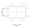
- 1 is a schematic diagram showing a usage state of the lottery game device according to the present embodiment.
- FIG. 1 is a perspective view showing an internal structure of the lottery game device according to the present embodiment.
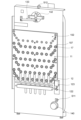
- 2 is a diagram showing the configuration of the front side of a first lottery game section of the lottery game device according to the present embodiment.
- FIG. 2 is a diagram showing the configuration of the rear side of a first lottery game section of the lottery game device according to the present embodiment.
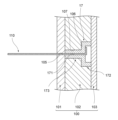
- FIG. 4 is a cross-sectional view showing a configuration of an attachment portion of a first lottery game unit of the lottery game device according to the present embodiment.
- FIG. 1 is a diagram showing a configuration of a supply unit of a first lottery game unit as seen from the front side of the lottery game device according to the present embodiment.
- FIG. 1 is a diagram showing a configuration of a supply section of a first lottery game section as seen from the back side of the lottery game device according to the present embodiment.
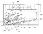
- FIG. 11A and 11B are diagrams for explaining the operation of supplying balls to the play unit by the supply unit of the first lottery game unit of the lottery game device according to the present embodiment.
- 11A and 11B are diagrams for explaining the operation of supplying balls to the play unit by the supply unit of the first lottery game unit of the lottery game device according to the present embodiment.
- FIG. 2 is a diagram showing a configuration of a second lottery game section of the lottery game device according to the present embodiment.
- 13 is a diagram showing a transport section of the second lottery game section of the lottery game device according to the present embodiment.
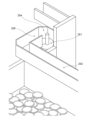
- FIG. 13 is a diagram showing an upper end portion of a transport section of a second lottery game section of the lottery game device according to the present embodiment.
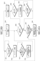
- FIG. 5 is a flowchart for explaining control of a lottery game by a control unit of the lottery game device according to the present embodiment.
- Figure 1 is a perspective view showing the configuration of the lottery game device 1.
- Figure 2 is a schematic diagram showing the lottery game device 1 in use.
- the lottery game device 1 is an example of a game device in which multiple players can simultaneously play their own lottery games.
- the lottery game includes, for example, a Corinth game played in a first lottery game section 10 described below, and a pusher game played in a second lottery game section 20 described below.
- the Corinth game is played using balls, which are an example of a play medium for the Corinth game.
- the play medium for the Corinth game may be something other than a ball, such as a medal or a cube, and may include two or more types of play media.
- the pusher game includes a ball pusher game played using a ball, and a medal pusher game played using medals. The ball pusher game and the medal pusher game are played simultaneously.
- the Corinth game can be played simultaneously with the pusher game.
- the lottery game device 1 is a lottery device for four players. As shown in FIG. 2, the lottery game device 1 comprises game devices 1A to 1D. Each of the game devices 1A to 1D has the same configuration. Therefore, by changing the number of game devices that make up the lottery game device 1, the number of players available for the lottery game device 1 can be changed to a number other than one or four. The following explanation focuses on the configuration of the game device 1A.
- FIG. 3 is a perspective view showing the internal structure of the lottery game device.
- Figures 4 to 6 are diagrams explaining the configuration of the first lottery game section 10.
- Figures 6 to 16 are diagrams explaining the configuration of the second lottery game section 20.
- the game device 1A comprises a first lottery game unit 10 for playing the Corinth game, a second lottery game unit 20 for playing the pusher game, an operation unit 30 for receiving operations from the player, a payout unit 40 for paying out game result media such as medals corresponding to the results of the lottery game to the player, a display unit 50 for displaying information related to the lottery game, a control unit 60 for executing the lottery game by controlling the operation of each of the first lottery game unit 10, the second lottery game unit 20, the operation unit 30, the payout unit 40, and the display unit 50, and a housing 70 for supporting or housing the above-mentioned configuration.
- the first lottery game unit 10 and the display unit 50 are arranged on the upper rear side of the second lottery game unit 20, vertically to the upper surface of the second lottery game unit 20.
- the first lottery game unit 10 and the display unit 50 may be arranged at an angle or horizontally to the upper surface of the second lottery game unit 20.
- the operation unit 30 and the payout unit 40 are attached to the housing 70.
- the display unit 50 is arranged inside the housing 70.
- the first lottery game unit 10 is an example of a game device that plays a game using a ball.
- the first lottery game unit 10 includes a play unit 10a that plays a first lottery game using a ball, a supply unit 10b that supplies balls for the first lottery game to the play unit 10a, and a storage unit 10c that stores balls discharged (dropped) from the play unit 10a and moves the stored balls toward the supply unit 10b.
- the details of each configuration of the first lottery game unit 10 will be described in the order of the play unit 10a, the storage unit 10c, and the supply unit 10b.
- the play unit 10a comprises a play board 11 having a base unit 100 and a plurality of guide pins 110 provided on the base unit 100, a receiving unit 12 provided on the first end 100a side of the base unit 100, and an insertion unit 13 provided on the second end 100b side of the base unit 100 for inserting a ball toward the plurality of guide pins 110 so that the ball reaches the receiving unit 12.
- the base part 100 has a decorative plate 101 on which information about the Corinth Game is printed, a mounting plate 102 for mounting a guide pin 110 provided on the back surface of the decorative plate 101, and a cover 103 for fixing the guide pin 110 mounted on the mounting plate 102.
- the decorative plate 101 is provided with a plurality of holes 105 for passing the guide pins 110
- the mounting plate 102 is provided with a plurality of holes 107 for mounting the guide pins 110.
- the holes 107 have a step part 106 as shown in FIG.
- the guide pin 110 is a component for changing the movement mode of a ball, which is an example of a play medium, by contacting the ball and causing the ball to bounce.
- the guide pin 110 is made of, for example, a metal material. As shown in FIG. 6 , the guide pin 110 is attached to the base part 100 via an attachment part 17 without being in direct contact with the base part 100.
- the mounting portion 17 is made of a material, such as resin, that has a lower hardness than the guide pin 110.
- vibrations of the guide pin 110 can be absorbed compared to attaching the guide pin 110 directly to the base portion 100, and by using a material that is lower in hardness than the material of the base portion 100, it is possible to reduce wear on the base portion 100 caused by vibrations of the mounting portion 17.
- the orientation and mounting accuracy of the guide pin 110 relative to the base portion 100 can be easily maintained.
- the mounting portion 17 has a retaining hole 171, a large diameter portion 172, and a small diameter portion 173.
- the guide pin 110 is attached to the retaining hole 171 and fixed integrally with the mounting portion 17.
- the integrated guide pin 110 and mounting portion 17 are fixed in position relative to the base portion 100 with the large diameter portion 172 sandwiched between the step portion 106 of the hole portion 107 of the mounting plate 102 and the cover 103. In this way, vibrations of the guide pin 110 can be absorbed, and the posture and mounting accuracy of the guide pin 110 relative to the base portion 100 can be easily maintained.
- the multiple guide pins 110 are provided in multiple rows on the base portion 100 along the longitudinal direction of the base portion 100.
- the multiple rows are seven rows, from the first row L1 to the seventh row L7.
- the longitudinal direction of the base portion 100 is an example of the specified direction of the base portion 100.
- the specified direction may be a direction other than the longitudinal direction depending on the arrangement method of the base portion 100 and changes in the shape of the base portion 100.
- the multiple guide pins 110 are configured so that the elasticity of at least one guide pin is different from that of the other guide pins and/or the inter-row distance of at least one of the multiple rows is different from the inter-row distance in order to change and adjust the movement mode of the ball.
- the greater the elasticity of the guide pin the greater the force (bouncing force) exerted on the ball that comes into contact with that guide pin. As a result, the ball bounces a greater distance.
- the force (bouncing force) exerted on the ball that comes into contact with that guide pin is small. As a result, the ball bounces a smaller distance.
- the greater the inter-row distance the smaller the constraint on the ball's bouncing range. As a result, the ball bounces a larger range.
- the constraint on the ball's bouncing range is large. As a result, the ball bounces a smaller range.
- the elasticity of the guide pin 110 can be varied by various methods.
- the diameter (i.e., thickness) of the guide pin 110 may be varied.
- the larger the diameter the smaller the elasticity of the guide pin 110.
- the material of the guide pin 110 may be varied.
- the greater the elasticity of the material constituting the guide pin 110 the greater the elasticity of the guide pin 110.
- the length of the portion of the guide pin 110 that protrudes from the base part 100 i.e., the length of the portion actually used during the game, may be varied.
- the guide pin 110 may be configured by combining some or all of these methods.
- the multiple guide pins 110 include at least two types of guide pins: a first guide pin 111 having a first elasticity, and a second guide pin 112 having a second elasticity greater than the first elasticity.
- the second guide pins 112 are arranged closer to the first end 100a of the base portion 100 than the first guide pins 111.
- the number of rows formed by the second guide pins may be greater than the number of rows formed by the first guide pins.
- the first guide pins 111 form the first row L1 closest to the throw-in section 13, and the second guide pins 112 form the second row L2 to the seventh row L7. In this way, the player can easily throw the ball into the row between the guide pins 110 they are aiming for.
- At least one inter-row distance is formed to be larger than the other inter-row distances. Furthermore, the at least one inter-row distance may be formed closer to the first end 100a than the second row L2, which is closer to the second end 100b of the base portion 100.
- the line distance between the first row L1 and the second row L2 is D1
- the line distance between each of the second row L2 to the seventh row L7 is D2.
- the line distance D1 is smaller than the line distance D2.
- the line distance closest to the insertion section 13 is the smallest. In this way, by moving the ball closer to the reception section 12, the bouncing range of the ball can be increased, the falling time of the ball can be extended, and the player's anticipation for the lottery game can be improved.
- the throw-in unit 13 is an example of a configuration for throwing balls toward the multiple guide pins 110 so that the balls reach the receiving unit 12.
- the throw-in unit 13 has a tip portion 131, a base portion 132 to which the tip portion 131 is attached, and a drive portion 133 for transmitting a drive force to the base portion 132 for rotating the base portion 132 back and forth in the direction shown in Figure 4.
- the tip portion 131 can rotate to throw balls into each column of the guide pins 110 in the first row L1.
- the reception unit 12 is an example of a trigger for advancing the lottery game by detecting a ball. As shown in Figs. 4 and 5, the reception unit 12 is provided below the guide pins 110 and above the storage unit 10c. Depending on the configuration of the guide pins 110, the reception unit 12 may be provided within the area of the base unit 100 where the guide pins 110 are provided, or may be provided above the guide pins 110.
- the reception unit 12 has a guide plate 121 that defines seven columns R1 to R7, a ball support unit 122 that is provided below the columns R2 to R6 and can move up and down, a ball sensor 124 that can detect the presence or absence of a ball in each of the columns R1 to R7 or the passage of a ball, and a drive unit 123 that drives the up and down movement of the ball support unit 122.
- Each of columns R1 to R7 is located at a position corresponding to the top and bottom of each of the columns formed by the first guide pins 111 of the first row L1.
- the ball support portion 122 is first positioned at the exit of columns R2 to R6. Then, when a ball inserted by the insertion portion 13 enters columns R1 and R7, the ball passes through columns R1 and R7 and falls into the storage portion 10c. On the other hand, when a ball inserted by the insertion portion 13 enters columns R2 to R6, the ball is supported by the ball support portion 122 so that it is located within columns R2 to R6.
- Each of the multiple ball sensors 124 can detect ball information of the balls received in each of columns R1 to R7, for example, the presence or absence of balls that have passed through columns R1 and R7, the presence or absence of balls stored in each of columns R2 to R6, the number of balls stored in each of columns R2 to R6, and whether the type of ball (color, etc.) is the same or different.
- each of the multiple ball sensors 124 detects ball information, it can transmit the detected ball information to the control unit 60, and under the control of the control unit 60, operate the ball support unit 122 that can move up and down, and a lottery (physical lottery and programmatic lottery) or other components of the game device 1A (for example, the second lottery game unit 20).
- the ball support 122 which can move up and down, moves up and down under the control of the control unit 60 to open and close the exits of the columns R2 to R6.
- the control unit 60 can start the downward movement of the ball support 122 based on the ball information of the columns R1 to R7 from the multiple ball sensors 124.
- the control unit 60 judges whether the ball sensor 124 has entered the same column as a previous ball in the same game, and whether two balls are overlapped when the ball sensor 124 continues to detect the ball. If both of these judgment results are "yes," the control unit 60 can move the ball support 122 downward so that the ball stored in the column falls into the storage unit 10c.
- the storage unit 10c is an example of a configuration for temporarily storing balls discharged from the play unit 10a. As shown in Figs. 4, 7, and 8, the storage unit 10c includes a first guide plate 161, a second guide plate 162, and a storage space 163 located between the first guide plate 161 and the second guide plate 162.
- the first guide plate 161 is provided above the supply unit 10b.
- the first guide plate 161 is configured to be extendable and contractible. Specifically, the first guide plate 161 can be adjusted within a range from the length corresponding to columns R1 to R3 to the length corresponding to columns R1 to R5. In this way, the first guide plate 161 can guide balls that fall from the column corresponding to that length into the storage space 163 so that those balls do not collide directly with the components of the supply unit 10b. On the other hand, balls that fall from the column corresponding to the portion where the first guide plate 161 is not provided fall directly into the storage space 163 through an opening above the storage space 163.
- the second guide plate 162 is an example of a configuration that moves the balls stored in the storage space 163 toward the supply section 10b. As shown in FIG. 14, the second guide plate 162 is disposed at an incline with respect to the horizontal direction so that the balls in the storage space 163 move forward toward the supply section 10b by their own weight.
- a configuration other than the second guide plate 162 may be used to move the balls contained in the storage space 163 toward the supply section 10b.
- a piston configuration for pushing the balls provided on a horizontally arranged ball support plate toward the supply section 10b may be used.
- the supply unit 10b is an example of a configuration for transporting balls to the play unit 10a. As shown in Fig. 4 and Fig. 7, the supply unit 10b includes a transport unit 14 that transports balls to the input unit 13 of the play unit 10a, and a guide unit 15 that continuously guides the balls from the storage unit 10c to the transport unit 14.
- a transport path P1 is provided between the transport unit 14 and the input unit 13, connecting the two.
- the transport path P1 has an entrance P11 on the transport unit 14 side, and an exit P12 located on the input unit 13 side.
- An exit sensor S12 is provided at the exit P12 of the transport path P1, which detects the presence or absence of a ball at the exit P12. For example, when the exit sensor S12 detects that there is no ball at the exit P12, it transmits that information to the control unit 60. When the control unit 60 receives a signal from the exit sensor S12, it rotates the transport unit 14.
- the transport unit 14 is an example of a configuration that transports balls one by one to the transport path P1. A ball that has been transported to the entrance P11 by the transport unit 14 is pushed by a ball that has been transported to the entrance P11 thereafter, and is moved along the transport path P1 to the exit P12.
- the conveying unit 14 has a conveying plate 141, a driving unit 140 for driving the rotation of the conveying plate 141, an attachment unit 144 attached to the back surface of the conveying plate 141 so as to transmit the driving force from the driving unit 140 to the conveying plate 141, and five engagement units 145 attached to the conveying plate 141.
- the transport plate 141 is star-shaped.
- the transport plate 141 has five protrusions 142 and recesses 143 formed between two adjacent protrusions 142.
- the five protrusions 142 are provided at equal intervals around the periphery of the transport plate 141.
- the length of each protrusion 142 is equal to or less than the radius of the ball.
- Each recess 143 has a shape corresponding to the outer shape of each ball so that it can hold one ball. Below, the position where the transport plate 141 starts to hold the ball via the recesses 143 may be referred to as the "transport start position.”
- an entrance sensor S11 is provided to detect whether the conveying plate 141 is rotating. For example, when the conveying plate 141 is not rotating due to damage or clogging, the entrance sensor S11 detects this information and transmits it to the control unit 60. When the control unit 60 receives a signal from the entrance sensor S11, it can stop the rotation of the conveying unit 14.
- the mounting portion 144 has a cylindrical configuration with a step. In the direction of its central axis, the mounting portion 144 has a large diameter portion 144a fixed to the conveying plate 141, a small diameter portion 144b fixed to the rotating shaft (not shown) of the driving portion 140, and a step surface 144c located between the large diameter portion 144a and the small diameter portion 144b. This mounting portion 144 allows the driving force from the driving portion 140 to be transmitted to the conveying plate 141.
- each engagement part 145 has an engagement end 146 that protrudes from the stepped surface 144c of the mounting part 144.
- the engagement end 146 is configured to be able to engage with or separate from the guide part 15.
- the drive unit 140 operates under the control of the control unit 60 to rotate the transport plate 141.
- the control unit 60 receives a signal from the player to insert a ball into the play unit 10a or a signal from the exit sender S12 that there is no ball at the exit P12, the control unit 60 can start the drive unit 140 to rotate the transport plate 141.
- the control unit 60 may also start the drive unit 140 continuously or at regular time intervals to rotate the transport plate 141 continuously or at regular time intervals.
- the drive unit 140 drives the operation of the guide portion 15.
- the drive unit 140 does not drive the operation of the guide portion 15.
- the guide unit 15 is an example of a configuration that realizes continuous guidance of balls to the transport unit 14.
- continuous guidance of balls means that when multiple balls are supplied from the storage unit 10c to the supply unit 10b, the guide unit 15 guides multiple balls one by one from the storage unit 10c to the supply unit 10b to the transport start position in sequence each time there is no ball at the transport start position of the transport unit 14 so that the transport unit 14 can transport the ball to the transport path P1 at any time.
- the absence of a ball at the transport start position is due to the storage unit 10c not supplying a ball to the supply unit 10b or the transport unit 14 transporting a ball at the transport start position to the transport path P1.
- the guide unit 15 guides another ball to the transport start position of the transport unit 14.
- the guide unit 15 is disposed below the first guide plate 161 and near the transport unit 14, as shown in Figs. 7 and 8.
- the guide unit 15 has a guide passage 151 that passes the balls from the storage unit 10c one by one toward the transport unit 14, and an adjustment unit 152 that moves at least one of the overlapping balls to another position in the storage unit 10c when the balls near an entrance 1511 on the storage unit 10c side of the guide passage 151, which will be described later, are overlapping and exceed the height of the entrance 1511.
- the guide passage 151 is an example of a configuration that connects the storage section 10c and the transport section 14. As shown in Figures 7 and 8, the guide passage 151 is a space defined by the adjustment section 152 and a guide plate 159 provided at a position opposite the adjustment section 152.
- the guide plate 159 is an example of a wall that supports the balls and supplies them to the transport start position of the transport section 14.
- the guide plate 159 is positioned at an angle to the horizontal direction so that the balls from the storage section 10c move forward toward the transport section 14 under their own weight.
- the guide plate 159 is connected to a second guide plate 162 of the storage section 10c.
- the guide passage 151 has an entrance 1511 located on the side of the storage section 10c and an exit 1512 located on the side of the conveying section 14.
- the entrance 1511 is formed to allow balls from the storage section 10c to enter the guide passage 151 one by one.
- the exit 1512 is formed to discharge the balls in the guide passage 151 one by one to the conveying section 14.
- the guide passage 151 is configured to align the balls in a row in which adjacent balls are in contact with each other.
- the guide passage 151 can align a row containing, for example, three balls.
- the row is supported by the guide plate 159 and can move along the guide plate 159 by its own weight to the transport start position of the transport unit 14.
- the transport unit 14 can transport the first ball in the row to the transport path P1, while the second ball can move along the guide plate 159 by its own weight to the transport start position.
- the transport unit 14 transports the second ball to the transport path P1, while the third ball can move along the guide plate 159 by its own weight to the transport start position.
- the balls in the row are guided one by one in succession to the transport start position by the guide plate 159, and the transport unit 14 can transport the ball that is at the transport start position at any time to the transport path P1.
- the adjustment unit 152 is an example of a configuration that eliminates overlapping of balls near the entrance 1511 of the guide passage 151 in the storage unit 10c.
- the adjustment unit 152 moves at least one of the balls in the second layer to another position in the storage unit 10c. Note that by changing the installation position, size, configuration, etc. of the adjustment unit 152, the adjustment unit 152 may be configured to move the position of other layers of balls among the two or more layers of balls stacked together, or multiple layers of balls.
- the adjustment unit 152 also has a piston structure that pushes the ball in a direction away from the inlet 1511. Specifically, as shown in Figures 7 and 8, the adjustment unit 152 has a base unit 153, a piston pin 154 that is attached to the base unit 153 so as to be capable of reciprocating motion, and a compression spring 155 that is provided between the base unit 153 and the piston pin 154.
- the base portion 153 has a fixed portion 1531 that is fixed to the base portion 100, two support portions 1532 that support the piston pin 154, and a long hole 1533 provided in the fixed portion 1531.
- the piston pin 154 includes a push block 156 at one end of the piston pin 154, an engagement portion 157 at the other end of the piston pin 154, and a pin 158 that limits the range of movement of the piston pin 154.
- the pin 158 is provided on the piston pin 154 so that both ends protrude from the surface of the piston pin 154 in the radial direction of the piston pin 154.
- One end of the pin 158 is slidably inserted into the long hole 1533 of the base portion 153.
- a compression spring 155 is provided between the other end of the pin 158 and the support portion 1532 on the conveying portion 14 side.
- the push block 156 is an example of a configuration for adjusting the contact position between the piston pin 154 and the balls and the pushing direction when the piston pin 154 performs a piston action.
- the push block 156 is a pentagon. With such a push block 156, when the piston pin 154 is pushed out, it comes into contact with a position corresponding to the center of gravity of one of the overlapping balls in the second layer that is located closest to the inlet 1511, and can push that ball downward in a direction away from the inlet 1511.
- the push block 156 may have a shape other than a pentagon depending on the characteristics of the ball, such as its size, material, and weight.
- the push block 156 may also push the ball upward in a direction away from the inlet 1511 or in a direction horizontal to the direction away.
- the engaging portion 157 is L-shaped. As shown in FIG. 8, the engaging portion 157 has a first portion 1571 and a second portion 1572. The engaging portion 157 can sequentially engage with and then separate from the five engaging ends 146 of the conveying portion 14 as the position of the five engaging ends 146 changes due to the rotation of the conveying plate 141. By engaging the engaging portion 157 with the engaging ends 146 of the conveying plate 141 in this manner, the piston pin 154 is driven by the drive portion 140 of the conveying portion 14. The details of the engagement and separation between the engaging portion 157 and the five engaging ends 146 of the conveying portion 14 will be described in detail in the section "Conveyance and adjustment of balls by the supply portion 10b" below.
- the piston pin 154 is described as being driven by the drive unit 140 of the conveying unit 14 via the engagement between the engagement portion 157 and the engagement end 146 of the conveying plate 141, but this is not limited to the above.
- the piston pin 154 may be driven by a dedicated drive unit for the piston pin 154, for example, so as to perform a piston movement at regular intervals.
- the piston pin 154 may be driven by the weight of the overlapping balls, for example, when the balls are overlapping.
- the dedicated drive unit for the piston pin 154 is provided with an activation configuration for activating the dedicated drive unit.
- the dedicated drive unit for the piston pin 154 can be activated so that the piston pin 154 performs a piston movement.
- the piston pin 154 may be driven by a dedicated drive unit for the piston pin 154 only when the balls are overlapping on the entrance 1511 side of the guide path 151, for example.
- an overlap detection sensor is provided on the entrance 1511 side of the guide path 151 to detect whether or not a ball is overlapping on the entrance 1511 side of the guide path 151. In this way, when the overlap detection sensor detects that a ball is overlapping on the entrance 1511 side of the guide path 151, it transmits a signal to the control unit 60. Then, based on the signal from the overlap detection sensor, the control unit 60 starts a dedicated drive unit for the piston pin 154 so that the piston pin 154 performs a piston movement.
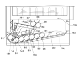
- the transport and adjustment of balls by the supply unit 10b will be described using the example shown in Figures 9 to 13.
- the guide passage 151 has already aligned one row made up of balls B2 to B4.
- the storage unit 10c also stores balls B5 and B6.
- the layer of balls B5 and B6 supported by the second guide plate 162 may be referred to as the "first layer.”
- the conveying plate 141 conveys the ball B1 held in the first recess 143 to the conveying path P1.
- the guide plate 159 of the adjustment unit 152 supplies the ball B2 to the second recess 143 of the conveying plate 141. In this way, it is possible to eliminate the problem of ball clogging caused by the engagement between the protrusion 142 of the conveying plate 141 and the ball B2, which occurs when the ball B2 is supplied to the conveying plate 141 after the conveying of the ball B1 by the conveying plate 141.
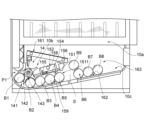
- the engagement end 146 provided at a position corresponding to the second recess 143 engages with the engagement portion 157 of the piston pin 154 of the adjustment portion 152.
- the compression spring 155 of the adjustment portion 152 is compressed by the force from the conveying plate 141, and the piston pin 154 moves to the first position W1, which is closer to the conveying portion 14 than the standby position.
- the conveying plate 141 continues to rotate, the ball B2 held by the second recess 143 is conveyed toward the conveying path P1, and the engaging end 146 slides along the second part 1572 (see FIG. 8) of the engaging part 157 of the piston pin 154, and then slides off the second part 1572.
- the engagement between the engaging end 146 and the engaging part 157 i.e., the engagement between the adjustment part 152 and the conveying part 14, is released.
- the compressed compression spring 155 is no longer subjected to force from the conveying plate 141, as shown in FIG. 12, and expands in the direction opposite to the direction of compression, returning to its original length.
- the piston pin 154 is subjected to an elastic force from the compression spring 155 in the direction opposite to the direction of compression, and is pushed out along that opposite direction, moving to the second position W2, which is closer to the storage part 10c than the standby position.
- This movement causes the push block 156 of the piston pin 154 to push the ball B9 in the second layer away from the entrance 1511 of the guide passage 151.
- the movement of ball B9 also causes the balls B6 to B8 in the first layer to move away from the entrance 1511 due to the force from ball B9, forming a space S between balls B5 and B6.
- the piston pin 154 eliminates the overlap of the balls on the entrance 1511 side of the guide passage 151, and it is possible to prevent the balls from getting stuck between the ball movement paths, i.e., between the first guide plate 161 and the second guide plate 162, due to the overlap of the balls.
- the engagement portion 157 (see FIG. 8) of the piston pin 154 engages with the other engagement ends 146 in sequence, and the piston pin 154 repeats the above-mentioned adjustment to the ball by engaging and separating the piston pin 154 from the first engagement end 146.
- the piston pin 154 can perform piston movements at regular intervals by engaging and separating the engagement portion 157 with the five engagement ends 146 of the conveying portion 14.
- the second lottery game unit 20 includes a placement surface 21 on which medals and balls are placed, a pusher table 22 that moves the medals and balls placed on the placement surface 21, a drop hole 23 through which the medals and balls placed on the placement surface 21 fall, a medal supply unit 24 that supplies medals to the placement surface 21, and a ball supply unit 25 that supplies balls to the placement surface 21.
- the placement surface 21 is configured to be used in a pusher game. As shown in Fig. 3, the placement surface 21 is provided such that its longitudinal direction is aligned with the width direction of the game device 1A. Furthermore, the placement surface 21 can hold medals supplied by the medal supply unit 24 and balls supplied by the ball supply unit 25.
- the pusher table 22 is configured to be used in a medal pusher game and a ball pusher game.
- the pusher table 22 is provided above the placement surface 21 and at one end side in the longitudinal direction of the placement surface 21. Under the control of the control unit 60, the pusher table 22 can horizontally move back and forth in the direction along the longitudinal direction of the placement surface 21 as indicated by the arrows in FIG. 14 .
- the drop opening 23 is a configuration used in a pusher game.
- the drop opening 23 is provided on the other end side in the longitudinal direction of the placement surface 21.
- the medals and balls pushed by the pusher table 22 can fall from the placement surface 21 through the drop opening 23.
- the drop opening 23 has a recovery path 231 that guides the movement of the dropped medals and balls.
- the recovery path 231 is connected to the medal supply unit 24 and the ball supply unit 25.
- the medal supply unit 24 is configured to supply medals for the medal pusher game to the placement surface 21. As shown in Fig. 3, the medal supply unit 24 has a medal storage unit 241 and a transport unit 242 that transports medals in the medal storage unit 241 to the placement surface 21. The medals that have fallen from the drop port 23 are transported to the medal storage unit 241 via a recovery path 231.
- the ball supply unit 25 is configured to supply balls for the ball pusher game to the placement surface 21. As shown in Figures 3 and 7 to 9, the ball supply unit 25 has a spiral transport lift 251 and a guide unit 252 that guides the ball transported from the transport lift 251 to a position on the placement surface 21 where it does not interfere with the movement range of the pusher table 22.
- the transport lift 251 has a transport inlet 253 on its lower side and a transport outlet 254 on its upper side.
- the transport lift 251 can transport balls at the transport inlet 253 to the transport outlet 254 by rotating around a central axis 259.
- the transport inlet 253 is also directly connected to the recovery path 231. Therefore, balls that have fallen from the drop port 23 are transported directly to the transport inlet 253 on the lower side of the transport lift 251 via the recovery path 231, and then transported directly to the transport inlet 253 by the transport lift 251.
- the guide portion 252 has one end 255 and the other end 256.
- One end 255 is connected to the transport inlet 253.
- the other end 256 is positioned above the mounting surface 21 so that the ball can fall to a position that does not interfere with the movement range of the pusher table 22 on the mounting surface 21. In this way, the ball transported from the transport inlet 253 can enter the one end 255 and then be supplied to the mounting surface 21 from the other end 256 without colliding with the upper surface of the pusher table 22.
- the operation unit 30 is configured to receive various operations from the player. As shown in Fig. 3, the operation unit 30 includes a first operation unit 31 for controlling the rotation direction of the insertion unit 13, a second operation unit 32 for inserting a ball into the game board 11 by the insertion unit 13, a second operation unit 33 for paying back medals corresponding to the result of the lottery game, a start medium receiving unit 34 for receiving medals, which are an example of a game start medium for starting the lottery game, from the player, and a money bowl 35 for placing medals and the like owned by the player.
- a first operation unit 31 for controlling the rotation direction of the insertion unit 13
- a second operation unit 32 for inserting a ball into the game board 11 by the insertion unit 13
- a second operation unit 33 for paying back medals corresponding to the result of the lottery game
- a start medium receiving unit 34 for receiving medals, which are an example of a game start medium for starting the lottery game, from the player
- a money bowl 35 for placing medals and the like owned by the player
- the payout unit 40 is configured to pay out medals, which are an example of game result media corresponding to the results of the lottery game played by the player, to the player. As shown in Fig. 3, the payout unit 40 includes a storage unit 41 that stores medals inserted by the player and medals to be paid out to the player, a payout outlet 42, and a transport unit 43 that transports the medals stored in the storage unit 41 to the payout outlet 42.
- the medals circulating between the start medium receiving unit 34 and the payout unit 40 and the medals used in the medal pusher game described above are medals in different circulation systems. In other words, the medals used in the pusher game are not paid out to the player. Also, the circulation systems for the balls used in the Corinth game and the balls used in the ball pusher game are independent of each other.
- the display unit 50 is configured to display various game contents and game information related to the lottery game.
- the game contents according to this embodiment include a display of a part of the medal pusher game, and the game information according to this embodiment includes, for example, the number of medals inserted by the player into the starting medium receiving unit 34 and the change in that number, and information on the number of medals paid out, etc.
- Fig. 17 is a flow chart for explaining the control of the lottery game by the control unit 60.
- Steps S11, S21, S31 First, the control unit 60 starts the medal pusher game and the ball pusher game via the second lottery game unit 20 (steps S21, S31), and determines whether or not there is an input from the player to start the Corinth game (step S11).
- Steps S13, S14, S22 When there is an input from the player to start the Corinth game (YES in step S11), the control unit 60 starts the Corinth game via the first lottery game unit 10 (step S12). Next, the control unit 60 judges whether or not two balls have entered any one of the columns R2 to R6 of the reception unit 12 of the first lottery game unit 10 (step S13).
- the control unit 60 When two balls have entered any one of the columns R2 to R6 of the reception unit 12 (YES in step S13), the control unit 60 lowers the ball support unit 122 to drop the balls into the storage unit 10c (step S14), and then pays out medals to the payout unit 40 according to the ball storage situation in each column before the balls were dropped (for example, the number of balls lined up in each column). After that, the control unit 60 judges whether or not any medals have fallen into the drop hole 23 by pressing the pusher table 22 in the medal pusher game in progress (step S22).
- the control unit 60 has been described as starting a physical lottery for the lottery game based on the storage state of the balls actually stored in the reception unit 12, but this is not limited to this.
- the control unit 60 may perform a non-physical lottery (programmed lottery) based on a pre-stored program, without relying on the storage state of the balls in the reception unit 12.
- the control unit 60 can start a lottery in which the number of medals to be paid out varies depending on the column in which the ball is placed. Specifically, the control unit 60 can pay out a maximum of 100 medals when the ball enters column R4, and can pay out a maximum of 500 medals when the ball enters column 2.
- the control unit 60 can also start a lottery to determine the number of medals to be paid out, for example, on the condition that two balls overlap in any column. Specifically, the control unit 60 can start a lottery for up to 100 coins if there are balls in three of the columns R2 to R6, and can start a lottery for up to 500 coins if there are balls in the pockets in four of the columns R2 to R6.
- Step S32 and S33 If no medals have fallen into the drop hole 23 (NO in step S22), the control unit 60 determines whether or not any balls have fallen into the drop hole 23 by pushing the pusher table 22 in the ongoing ball pusher game (step S32). If any balls have fallen into the drop hole 23 (YES in step S32), the control unit 60 starts a jumbo lottery (step S33).
- the jumbo lottery held in step S33 is a lottery game that is the same as the Corinth game held in steps S11 to S14, but the only difference is the number of medals paid out that correspond to the lottery results. For this reason, a detailed explanation of the jumbo lottery will be omitted. Note that the jumbo lottery may be a lottery game other than the Corinth game.
- Step S34, S41, S51 the control unit 60 judges whether the jumbo lottery has ended (step S34). If the jumbo lottery has ended (YES in step S34), the control unit 60 judges whether the player has performed an operation to pay out medals (step S41). If the player has performed an operation to pay out medals (YES in step S41), the control unit 60 pays out medals to the payout opening 42 in a number corresponding to both the lottery result of the Corinth game and the ball lottery result of the ball pusher game, i.e., the lottery result of the jumbo lottery (step S51), and ends the lottery game.
- step S11 if there is no input from the player to start the Corinth game (NO in step S11), the control unit 60 returns the process to step S11. If two balls are not in any one of the columns R2 to R6 of the reception unit 12 (NO in step S13), the control unit 60 returns the process to step S13.
- step S41 determines whether or not the player has performed an operation to pay out medals. In this case, if there has been an operation to pay out medals from the player (YES in step S41), the control unit 60 pays out to the payout opening 42 a number of medals that correspond to the lottery results of the Corinth game, the lottery results of the medal lottery, and/or the ball lottery results of the ball pusher game (step S51), and ends the lottery game.
- step S41 determines whether or not the player has performed an operation to pay out medals. In this case, if the player has performed an operation to pay out medals (YES in step S41), the control unit 60 pays out to the payout opening 42 a number of medals corresponding to the lottery results of the Corinth game and the medal lottery (step S51), and ends the lottery game.
- step S41 if there is no operation from the player to pay out medals (NO in step S41), the control unit 60 returns the process to step S11. In other words, if there is no operation from the player to pay out medals, the control unit 60 can repeatedly play the Corinth game, the medal pusher game, and the ball pusher game.
- the first lottery game unit 10 comprises a play unit 10a in which a first lottery game is played using balls, a supply unit 10b which supplies game balls to the play unit 10a, and a storage unit 10c having a second guide plate 162 which is an example of a configuration for storing balls discharged from the play unit 10a and moving the stored balls towards the supply unit 10b.
- the supply unit 10b comprises a transport unit 14 which transports balls to the play unit 10a, and a guide unit 15 which continuously guides balls from the storage unit 10c to the transport unit 14.
- the guide unit 15 is configured to comprise a guide passage 151 which allows the balls from the storage unit 10c to pass one by one towards the transport unit 14, and an adjustment unit 152 which, when balls near an entrance 1511 on the storage unit 10c side of the guide passage 151 are overlapping above the height of the entrance 1511, moves at least one of the overlapping balls to another position in the storage unit 10c.
- the effect of the first lottery game unit 10 adopting the guide unit 15 will be described in more detail.
- the first lottery game unit 10 guides the balls from the storage unit 10c one by one continuously to the transport unit 14 via the guide passage 151, thereby avoiding both the ball jamming problem on the transport unit 14 side, where the transport unit 14 and the balls mesh due to the time difference between the start time of the transport operation of the transport unit 14 and the time the balls are guided to the transport unit 14, and the ball jamming problem that may occur in the guide passage 151.
- the first lottery game unit 10 solves the ball overlap problem near the entrance 1511 of the guide passage 151 via the adjustment unit 152, thereby avoiding the interruption or suspension of the guidance of the balls to the transport unit 14 due to ball jamming that may occur in the ball movement path of the first lottery game unit 10 due to the overlapping of the balls.
- the first lottery game unit 10 can eliminate ball clogging near the transport unit 14 and on the side of the storage unit 10c away from the transport unit 14.
- ball transport by the transport unit 14 can be achieved stably, improving the player's satisfaction with the game.
- the guide passage 151 has an entrance 1511 and an exit 1512 located on the transport unit 14 side, the entrance 1511 being formed to allow balls from the storage unit 10c to enter the guide passage 151 one by one, and the exit 1512 being formed to discharge the balls in the guide passage 151 one by one to the transport unit 14.
- the guide passage 151 can be configured to guide the balls one by one to the transport unit with a simple structure, and the occurrence of ball clogging while moving toward the transport unit 14 can be avoided.
- the guide passage 151 can align the multiple balls in a row in which adjacent balls come into contact with each other before the multiple balls enter the entrance 1511 from the storage unit 10c in sequence and are discharged from the exit 1512. As a result, it is easy to avoid ball jams caused by the balls engaging with the transport unit 14.
- the adjustment unit 152 can have a piston configuration that pushes the ball in a direction away from the entrance 1511 of the guide passage 151. As a result, it is possible to reliably prevent the occurrence of ball clogging on the entrance 1511 side of the guide passage 151 using a simple configuration.
- the supply unit 10b further includes a drive unit 140 that drives the ball transporting operation of the transport unit 14, and the piston pin 154 of the piston configuration of the adjustment unit 152 is formed to be engageable with the transport unit 14, and when the piston pin 154 is engaged with the transport unit 14, the piston operation of the piston pin 154 can be driven by the drive unit 140.
- the drive unit 140 drives the ball transporting operation of the transport unit 14 and the piston pin 154 of the piston configuration of the adjustment unit 152 to be engageable with the transport unit 14, and when the piston pin 154 is engaged with the transport unit 14, the piston operation of the piston pin 154 can be driven by the drive unit 140.
- the guide passage 151 can be defined by the adjustment unit 152 and the guide plate 159, which is an example of a wall portion that supports the ball and is provided in a position opposite the adjustment unit 152.
- the guide passage 151 can be formed with a simple structure, making it possible to reduce the number of components.
- the lottery game device 1 is configured to include the lottery game device 1, which is an example of a lottery game unit for playing a lottery game using any one of the first lottery game units 10 described above, a start medium receiving unit 34 that receives a game start medium through a player's operation, a payout unit 40 that pays out game result media to the player, and a control unit 60 configured to pay out game result media corresponding to the lottery result to the payout unit 40 based on the lottery result of the lottery game started by the lottery game device 1 when the start medium receiving unit 34 receives the game start medium.
- the lottery game device 1 is an example of a lottery game unit for playing a lottery game using any one of the first lottery game units 10 described above
- a start medium receiving unit 34 that receives a game start medium through a player's operation
- a payout unit 40 that pays out game result media to the player
- a control unit 60 configured to pay out game result media corresponding to the lottery result to the payout unit 40 based on the lottery result of the lottery game started by the lottery game device 1 when the
- the present invention is not limited to the above embodiments, and designs made by a person skilled in the art that have been appropriately modified from these embodiments are also included within the scope of the present invention as long as they comprise the features of the present invention.
- gaming machines other than the Corinth Game smart ball cabinets, and other gaming devices that use guide pins, a game board, and a game medium are also included within the scope of the present invention.
- the elements of the above embodiments and their arrangement, materials, conditions, shapes, sizes, etc. are not limited to those exemplified, and can be modified as appropriate.
- the elements of the above embodiments can be combined to the extent technically possible, and combinations of these are also included within the scope of the present invention as long as they comprise the features of the present invention.
- Lottery game device 10 First lottery game section 10a: Play section 10b: Supply section 10c: Storage section 14: Transport section 15: Guide section 34: Start medium receiving section 40: Payout section 60: Control section 140: Drive section 151: Guide passage 152: Adjustment section 159: Guide board 1511: Entrance 1512: Exit
Landscapes
- Physics & Mathematics (AREA)
- General Physics & Mathematics (AREA)
- Engineering & Computer Science (AREA)
- Multimedia (AREA)
- Pinball Game Machines (AREA)
- Slot Machines And Peripheral Devices (AREA)
Abstract
簡易な構成を用いて、搬送部に供給されるボールの詰まりの発生を回避し、搬送部によるボール搬送を安定的に実現させて、プレイヤのゲームに対する満足度を向上させることができるゲーム装置及び抽選ゲーム装置を提供する。ゲーム装置は、遊戯部10aと、遊戯部10aにボールを供給する供給部10bと、ボールを収容する収容部10cと、を備える。供給部10bは、ボールを遊戯部10aに搬送する搬送部14と、収容部10cからのボールを連続に搬送部14に案内する案内部15と、を有し、案内部15は、ボールを搬送部14に向けて通過させる案内通路151と、案内通路151の入口1511の近傍にあるボールが入口1511の高さを超えて重なっているとき、重なっているボールのうちの少なくとも1つを収容部10cの他の位置に移動させる調整部152と、を有する。
Description
本発明は、ゲーム装置及び抽選ゲーム装置に関する。
従来、ボールを一球ずつ遊戯部に搬送する搬送部を有するゲーム装置が知られている(例えば、特許文献1参照)。
ところで、特許文献1に開示された従来の抽選ゲーム装置は、ボールがボール移動通路において詰まるという問題を解消するために、詰まっているボールを回収レーンに押し付けるプッシュプレートを採用している。しかしながら、プッシュプレートが詰まっているボールを押し付けるとき、ボールの搬送部への案内が一時的に停止されるので、搬送部がボールを搬送できなくなる問題が発生することに加え、搬送部の搬送動作の開始時間と詰まりが解消されたボールが搬送部に案内される時間との時間差により、搬送部とボールとの噛み合いに起因するボール詰り問題が生じることがある。また、プッシュプレートの作用端が搬送部の近傍にあることで、プッシュプレートは、搬送部から離れたボール移動通路において生じるボールの詰まり問題を解消できないことがある。このように、プッシュプレートによりボールの詰まり問題の解消ができない場合、搬送部によるボールの安定搬送ができず、プレイヤのゲームに対する満足度に影響を与えるおそれがある。
本発明は、簡易な構成を用いて、搬送部に供給されるボールの詰まりの発生を回避し、搬送部によるボール搬送を安定的に実現させて、プレイヤのゲームに対する満足度を向上させることができるゲーム装置及び抽選ゲーム装置を提供することを目的とする。
前記目的を達成するため、本発明に係るゲーム装置は、ボールを用いてゲームを行う遊戯部と、遊戯部にゲーム用のボールを供給する供給部と、遊戯部から排出されるボールを収容し、かつ、収容されたボールを供給部に向かって移動させる構成を有する収容部と、を備え、供給部は、ボールを遊戯部に搬送する搬送部と、収容部からのボールを連続に搬送部に案内する案内部と、を有し、案内部は、収容部からのボールを搬送部に向けて通過させる案内通路と、案内通路の収容部側の入口の近傍にあるボールが入口の高さを超えて重なっているとき、重なっているボールのうちの少なくとも1つを収容部の他の位置に移動させる調整部と、を有するように構成されているものである。
かかる構成を採用すると、本発明によれば、簡易な構成を用いて、搬送部に供給されるボールの詰まりの発生を回避し、搬送部によるボール搬送を安定的に実現させて、プレイヤのゲームに対する満足度を向上させることができる。
本発明に係るゲーム装置において、案内通路は、入口と、搬送部側に位置する出口と、を有し、入口は、収容部からのボールを一球ずつ案内通路に進入させるように形成されており、出口は、案内通路内のボールを一球ずつ搬送部に排出させてもよい。
かかる構成を採用すると、案内通路による搬送部への一球ずつの案内が簡易な構成によって実現でき、搬送部に向かって移動中のボール詰まりの発生を回避することができる。
本発明に係るゲーム装置において、複数行のうち、収容部から複数のボールが順次入口に進入しかつ出口から排出される前に、案内通路は、複数のボールを、隣り合うボールが相互に接触する1つの列に整列させてもよい。
かかる構成を採用すると、搬送部とボールとの噛み合いによるボール詰まりの発生を回避することを簡単に実現できる。
本発明に係るゲーム装置において、調整部は、ボールを入口から離れる方向に向けて押し出すピストン構成を有してもよい。
かかる構成を採用すると、簡易な構成を用いて、案内通路の入口側のボール詰まりの発生を確実に回避することができる。
本発明に係るゲーム装置において、供給部は、搬送部のボール搬送動作を駆動する駆動部をさらに有し、調整部のピストン構成は、搬送部と係合可能に形成されており、ピストン構成と搬送部と係合しているとき、ピストン構成のピストン動作が駆動部によって駆動されてもよい。
かかる構成を採用すると、一つの動力源を用いて、搬送部及び調整部のそれぞれの動作を駆動することで、構造の簡易化及び製造コストの軽減を実現できる。
本発明に係るゲーム装置において、案内通路は、調整部と、調整部と対向する位置に設けられたボールを支持する壁部と、によって画定されててもよい。
かかる構成を採用すると、簡易な構成によって案内通路を形成することで、構成部品の軽減を可能にする。
本発明に係る抽選ゲーム装置において、上述したいずれか一つの抽選ゲーム装置を用いて抽選ゲームを行うための抽選ゲーム部と、プレイヤの操作により、遊戯開始媒体を受け付ける開始媒体受付部と、遊戯結果媒体をプレイヤに払い出す払出部と、開始媒体受付部が遊戯開始媒体を受け付けることにより開始された抽選ゲーム部による抽選ゲームの抽選結果に基づいて、抽選結果に対応する遊戯結果媒体を払出部に払い出すように構成された制御部と、を備えるものである。
かかる構成を採用すると、簡易な構成を用いて、第1抽選ゲーム部におけるボール詰まりの発生を回避し、抽選ゲームを安定的に実施させて、プレイヤのゲームに対する満足度を向上させることができる。
本発明によれば、簡易な構成を用いて、搬送部に供給されるボールの詰まりの発生を回避し、搬送部によるボール搬送を安定的に実現させて、プレイヤのゲームに対する満足度を向上させることができるゲーム装置及び抽選ゲーム装置を提供することが可能となる。
以下、各図を参照しながら、本実施形態について説明する。なお、図面の上下左右等の位置関係は、特に断らない限り、図面に示す位置関係に基づくものとする。また、図面の寸法比率は、図示の比率に限定されるものではない。さらに、以下の実施形態は、本発明を説明するための例示であり、本発明をこの実施形態のみに限定する趣旨ではない。またさらに、本発明は、その要旨を逸脱しない限り、様々な変形が可能である。
<抽選ゲーム装置1の概要>
まず、図1及び図2を参照しつつ、本実施形態に係る抽選ゲーム装置1の構成の概要及び抽選ゲーム装置1によって行われる抽選ゲームについて説明する。図1は、抽選ゲーム装置1の構成を示す斜視図である。図2は、抽選ゲーム装置1の使用状態を示す模式図である。
まず、図1及び図2を参照しつつ、本実施形態に係る抽選ゲーム装置1の構成の概要及び抽選ゲーム装置1によって行われる抽選ゲームについて説明する。図1は、抽選ゲーム装置1の構成を示す斜視図である。図2は、抽選ゲーム装置1の使用状態を示す模式図である。
本実施形態に係る抽選ゲーム装置1は、複数のプレイヤが各自の抽選ゲームを同時に行うことができる遊戯装置の一例である。ここで、抽選ゲームは、例えば、後述する第1抽選ゲーム部10において行われるコリントゲームと、後述する第2抽選ゲーム部20において行われるプッシャゲームと、を含む。コリントゲームは、コリントゲーム用の遊戯媒体の一例であるボールを用いて行われている。なお、コリントゲーム用の遊戯媒体は、メダルや立方体等の、ボール以外の物であってもよく、2種類以上の遊戯媒体を含んでもよい。プッシャゲームは、ボールを用いて行われるボールプッシャゲームと、メダルを用いて行われるメダルプッシャゲームと、を含む。ボールプッシャゲーム及びメダルプッシャゲームは、同時に行われる。コリントゲームは、プッシャゲームと同時に行われることができる。
抽選ゲーム装置1は、4人用の抽選装置である。抽選ゲーム装置1は、図2に示すように、ゲーム装置1A~1Dを備える。ゲーム装置1A~1Dの各々は、同じ構成を有する。このため、抽選ゲーム装置1を構成するゲーム装置の数を変更させることで、抽選ゲーム装置1の利用可能なプレイヤ数を、1人又は4人以外の人数に変更することができる。以下の説明では、ゲーム装置1Aの構成を中心に説明する。
<ゲーム装置1Aの詳細>
続いて、図1乃至図16を参照しつつ、本実施形態に係るゲーム装置1Aの重要構成の詳細について説明する。図3は、抽選ゲーム装置の内部構造を示す斜視図である。図4~図6は、第1抽選ゲーム部10の構成を説明する図である。図6~図16は、第2抽選ゲーム部20の構成を説明する図である。
続いて、図1乃至図16を参照しつつ、本実施形態に係るゲーム装置1Aの重要構成の詳細について説明する。図3は、抽選ゲーム装置の内部構造を示す斜視図である。図4~図6は、第1抽選ゲーム部10の構成を説明する図である。図6~図16は、第2抽選ゲーム部20の構成を説明する図である。
ゲーム装置1Aは、図1及び図3に示すように、コリントゲームを行うための第1抽選ゲーム部10と、プッシャゲームを行うための第2抽選ゲーム部20と、プレイヤからの操作を受け付ける操作部30と、抽選ゲームの結果に対応するメダル等の遊戯結果媒体をプレイヤに払い出す払出部40と、抽選ゲームに関する情報を表示する表示部50と、第1抽選ゲーム部10、第2抽選ゲーム部20、操作部30、払出部40、及び表示部50のそれぞれの動作を制御することで抽選ゲームを実行させる制御部60と、前述した構成を支持又は収容する筐体70と、を備える。
第1抽選ゲーム部10及び表示部50は、図3に示すように、第2抽選ゲーム部20の上方リア側に、第2抽選ゲーム部20の上面に対して垂直に配置されている。なお、第1抽選ゲーム部10及び表示部50は、第2抽選ゲーム部20の上面に対して傾斜又は水平に配置されてもよい。操作部30及び払出部40は、筐体70に取り付けられている。表示部50は、筐体70の内部に配置されている。
[第1抽選ゲーム部10]
次に、図4~13を参照しつつ、第1抽選ゲーム部10の構成について説明する。第1抽選ゲーム部10は、ボールを用いてゲームを行うゲーム装置の一例である。第1抽選ゲーム部10は、図4及び図5に示すように、ボールを用いて第1抽選ゲームを行う遊戯部10aと、遊戯部10aに第1抽選ゲーム用のボールを供給する供給部10bと、遊戯部10aから排出(落下)するボールを収容し、かつ、収容されたボールを供給部10bに向けて移動させる構成を有する収容部10cと、を備える。以下では、遊戯部10a、収容部10c、及び供給部10bの順で、第1抽選ゲーム部10の各構成の詳細について説明する。
次に、図4~13を参照しつつ、第1抽選ゲーム部10の構成について説明する。第1抽選ゲーム部10は、ボールを用いてゲームを行うゲーム装置の一例である。第1抽選ゲーム部10は、図4及び図5に示すように、ボールを用いて第1抽選ゲームを行う遊戯部10aと、遊戯部10aに第1抽選ゲーム用のボールを供給する供給部10bと、遊戯部10aから排出(落下)するボールを収容し、かつ、収容されたボールを供給部10bに向けて移動させる構成を有する収容部10cと、を備える。以下では、遊戯部10a、収容部10c、及び供給部10bの順で、第1抽選ゲーム部10の各構成の詳細について説明する。
[遊戯部10a]
遊戯部10aは、ベース部100及びベース部100に設けられた複数の案内ピン110を有する遊戯盤11と、ベース部100の第1端100a側に設けられた受付部12と、ベース部100の第2端100b側に設けられ、ボールが受付部12に到達するように、ボールを複数の案内ピン110に向けて投入する投入部13と、を備える。
遊戯部10aは、ベース部100及びベース部100に設けられた複数の案内ピン110を有する遊戯盤11と、ベース部100の第1端100a側に設けられた受付部12と、ベース部100の第2端100b側に設けられ、ボールが受付部12に到達するように、ボールを複数の案内ピン110に向けて投入する投入部13と、を備える。
(ベース部100)
ベース部100は、図4~図6に示すように、コリントゲームに関する情報が印刷された装飾板101と、装飾板101の背面に設けられた案内ピン110を取り付けるための取付板102と、取付板102に取り付けられた案内ピン110を固定するためのカバー103と、を有する。装飾板101には、案内ピン110を通過させるための複数の孔部105が設けられており、取付板102には、案内ピン110を取り付けるための複数の孔部107が設けられている。孔部107は、図6に示すように、段差部106を有する。
ベース部100は、図4~図6に示すように、コリントゲームに関する情報が印刷された装飾板101と、装飾板101の背面に設けられた案内ピン110を取り付けるための取付板102と、取付板102に取り付けられた案内ピン110を固定するためのカバー103と、を有する。装飾板101には、案内ピン110を通過させるための複数の孔部105が設けられており、取付板102には、案内ピン110を取り付けるための複数の孔部107が設けられている。孔部107は、図6に示すように、段差部106を有する。
(案内ピン110)
案内ピン110は、遊戯媒体の一例であるボールとの接触によって、ボールを跳ねさせながらボールの移動態様を変化させるための構成である。案内ピン110は、例えば、金属材料によって構成されている。案内ピン110は、図6に示すように、取付部17を介して、ベース部100と直接接触せずにベース部100に取り付けられている。
案内ピン110は、遊戯媒体の一例であるボールとの接触によって、ボールを跳ねさせながらボールの移動態様を変化させるための構成である。案内ピン110は、例えば、金属材料によって構成されている。案内ピン110は、図6に示すように、取付部17を介して、ベース部100と直接接触せずにベース部100に取り付けられている。
ここで、取付部17は、樹脂等の案内ピン110よりも硬度が低い材料によって構成されている。このような取付部17によれば、案内ピン110を直接ベース部100に取り付けることに比較して、案内ピン110の振動を吸収できるとともに、ベース部100の材料よりも硬度が低い材料を採用することで、取付部17が振動してベース部100を削ることを軽減することができる。その結果、案内ピン110のベース部100に対する姿勢及び取付精度を容易に維持することができる。
取付部17は、保持孔171と、径大部172と、径小部173と、を有する。案内ピン110は、保持孔171に取り付けられることで、取付部17と一体に固定されている。一体となった案内ピン110及び取付部17は、径大部172が、取付板102の孔部107の段差部106及びカバー103によって挟まれてベース部100に対する位置が固定されている。このように、案内ピン110の振動を吸収できるとともに、案内ピン110のベース部100に対する姿勢及び取付精度を容易に維持することができる。
複数の案内ピン110は、図4に示すように、ベース部100の長手方向に沿って、複数行に亘ってベース部100に設けられている。図4に示す例では、複数行は、第1行L1~第7行L7の7行である。また、ベース部100の長手方向は、ベース部100の所定方向の一例である。なお、所定方向は、ベース部100の配置方法及びベース部100の形状の変化よって、長手方向以外の方向であってもよい。
複数の案内ピン110は、ボールの移動態様を変化させて調整するために、少なくとも1つの案内ピンの弾性が他の案内ピンの弾性と異なる、及び/又は、複数行間の少なくとも1つの行間距離が他の行間距離と異なるように構成されている。ここで、案内ピンの弾性が大きくなるほど、その案内ピンと接触するボールに与える力(跳ねさせる力)が大きい。その結果、ボールの跳ねる距離が大きい。一方、案内ピンの弾性が小さいとき、その案内ピンと接触するボールに与える力(跳ねさせる力)が小さい。その結果、ボールの跳ねる距離が小さい。また、行間距離が大きくなるほど、ボールの跳ねる範囲への拘束が小さい。その結果、ボールの跳ねる範囲が大きい。一方、行間距離が小さいとき、ボールの跳ねる範囲への拘束が大きい。その結果、ボールの跳ねる範囲が小さい。
ここで、案内ピン110の弾性は、様々な方法によって異ならせることができる。例えば、案内ピン110の直径(すなわち、太さ)を異ならせるように構成してもよい。この場合、直径が大きくなるほど、案内ピン110の弾力が小さくなる。また、例えば、案内ピン110の材質を異ならせるように構成してもよい。この場合、案内ピン110を構成する材質の弾性が大きくなるほど、案内ピン110の弾力が大きくなる。また、例えば、案内ピン110のベース部100から突出する部分の長さ、すなわち、ゲーム中の実際使用される部分の長さを異ならせるように構成してもよい。この場合、案内ピン110の実際使用される部分の長さが長くなるほど、ボールと接触するときに、案内ピン110がボールからの衝突によってしなりやすくなり、案内ピン110の弾力が小さくなる。さらに、それらの方法のいくつか又は全部を組み合わせて案内ピン110を構成してもよい。
例えば、複数の案内ピン110は、第1弾性を有する第1案内ピン111と、第1弾性よりも大きい第2弾性を有する第2案内ピン112と、の少なくとも2種類の案内ピンを有する。複数行のうち、第2案内ピン112は、第1案内ピン111よりもベース部100の第1端100a側に配置されている。また、第2案内ピンによって構成された行の行数は、第1案内ピンによって構成された行の行数よりも多くなってもよい。
図4に示す例では、第1案内ピン111は、投入部13に最も近い第1行L1を構成し、第2案内ピン112は、第2行L2~第7行L7を構成している。このように、プレイヤが簡単に目指している案内ピン110の間の列にボールを投入することができる。
また、例えば、複数行によって構成された複数の行間距離のうち、少なくとも1つの行間距離は、他の行間距離よりも大きく形成されている。また、その少なくとも1つの行間距離は、ベース部100の第2端100bに近い側にある第2行L2よりも第1端100aに近い側に形成されてもよい。
図4に示す例では、第1行L1と第2行L2との間の行間距離はD1であり、第2行L2~第7行L7の各々の行間距離ともD2である。また、行間距離D1は、行間距離D2よりも小さい。すなわち、複数行によって構成された複数の行間距離のうち、投入部13に最も近い行間距離は、一番小さい。このように、受付部12に近づくことによりボールの跳ね範囲を増大することができ、ボールの落下時間を延長できるとともに、プレイヤの抽選ゲームへの期待感を向上させることができる。
(投入部13)
投入部13は、ボールが受付部12に到達するように、ボールを複数の案内ピン110に向けて投入するための構成の一例である。投入部13は、図4及び図5に示すように、先端部131と、先端部131が取り付けられた基部132と、基部132を図4に示す方向に往復回転させる駆動力を基部132に伝達するための駆動部133と、を有する。先端部131は、回転することで、ボールを第1行L1の案内ピン110の各列に投入することができる。
投入部13は、ボールが受付部12に到達するように、ボールを複数の案内ピン110に向けて投入するための構成の一例である。投入部13は、図4及び図5に示すように、先端部131と、先端部131が取り付けられた基部132と、基部132を図4に示す方向に往復回転させる駆動力を基部132に伝達するための駆動部133と、を有する。先端部131は、回転することで、ボールを第1行L1の案内ピン110の各列に投入することができる。
また、先端部131と第1行L1との最も近い距離を「l」とし、ボールの直径を「d」とする場合、「d」及び「l」は、d<l≦2dの関係を有する。このように配置された投入部13によれば、投入部13から投入された直後のボールの跳ね状態を抑えることができ、より容易にボールを目標の案内ピン110の間の列に投入することを実現できる。
(受付部12)
受付部12は、ボールを感知することで、抽選ゲームを進めさせるためのトリガの一例である。受付部12は、図4及び図5に示すように、複数の案内ピン110の下方かつ収容部10cの上方に設けられている。なお、複数の案内ピン110の構成に応じて、受付部12は、ベース部100の複数の案内ピン110が設けられた領域内に設けられてもよく、また、複数の案内ピン110よりも上方に設けられてもよい。受付部12は、7つの欄R1~欄R7を規定する案内板121と、欄R2~欄R6の下方に設けられた、上下移動可能なボール支持部122と、欄R1~欄R7の各々にボールの有無若しくはボールの通過の有無を検知するできるボールセンサ124と、ボール支持部122の上下移動を駆動する駆動部123と、を有する。
受付部12は、ボールを感知することで、抽選ゲームを進めさせるためのトリガの一例である。受付部12は、図4及び図5に示すように、複数の案内ピン110の下方かつ収容部10cの上方に設けられている。なお、複数の案内ピン110の構成に応じて、受付部12は、ベース部100の複数の案内ピン110が設けられた領域内に設けられてもよく、また、複数の案内ピン110よりも上方に設けられてもよい。受付部12は、7つの欄R1~欄R7を規定する案内板121と、欄R2~欄R6の下方に設けられた、上下移動可能なボール支持部122と、欄R1~欄R7の各々にボールの有無若しくはボールの通過の有無を検知するできるボールセンサ124と、ボール支持部122の上下移動を駆動する駆動部123と、を有する。
欄R1~欄R7の各々は、第1行L1の各第1案内ピン111によって構成された列の各々に対して、上下方向に対応する位置に設けられている。コリントゲームに係る抽選が行われるとき、ボール支持部122は、まず欄R2~欄R6の出口に位置する。そして、投入部13によって投入されたボールが欄R1及び欄R7に入ると、ボールは、そのまま欄R1及び欄R7に通過して収容部10cに落下する。一方、投入部13によって投入されたボールが欄R2~欄R6に入ると、ボールは、ボール支持部122によって欄R2~欄R6内に位置するように支持される。
複数のボールセンサ124の各々は、欄R1~欄R7の各々に受け付けられたボールのボール情報、例えば、欄R1及び欄R7に通過したボールの有無、欄R2~欄R6の各々に格納されたボールの有無、欄R2~欄R6の各々に格納されたボールの数、ボールの種類(色等)の異同等を検出することができる。また、複数のボールセンサ124の各々は、ボール情報を検出するとき、その検出したボール情報を制御部60に送信して、制御部60の制御のもとで、上下移動可能なボール支持部122と、抽選(物理的な抽選及びプログラム上の抽選)又はゲーム装置1Aの他の構成(例えば、第2抽選ゲーム部20)を動作させることと、を行わせることができる。
上下移動可能なボール支持部122は、制御部60の制御のもとで上下方向に移動して、欄R2~欄R6の出口を開閉する。具体的には、制御部60は、複数のボールセンサ124による欄R1~欄R7のボール情報に基づいて、ボール支持部122の下方への移動を起動させることができる。ここで、複数のボールセンサ124の各々は、例えば、1つ目のボールが欄R2~欄R6のいずれかに入ったときであっても、その後のほかのボールがその欄に通過を検知し、そして、欄R2~欄R6の一部又は全部においてボールが2つ重なった状態になるとき、制御部60は、同一ゲーム内でボールセンサ124が過去のボールと同じ欄に入ったことの有無と、ボールセンサ124がボールを検知し続けているとき、ボールが2つ重なった状態で有るか否かと、について判断する。それらの判断結果が何れも「有り」の場合、制御部60は、欄に格納しているボールを収容部10cに落下させるように、ボール支持部122を下方へ移動させることができる。
[収容部10c]
収容部10cは、遊戯部10aから排出されるボールの一時収容を行う構成の一例である。収容部10cは、図4、図7、及び図8に示すように、第1案内板161と、第2案内板162と、第1案内板161及び第2案内板162の間に位置する収容空間163と、を備える。
収容部10cは、遊戯部10aから排出されるボールの一時収容を行う構成の一例である。収容部10cは、図4、図7、及び図8に示すように、第1案内板161と、第2案内板162と、第1案内板161及び第2案内板162の間に位置する収容空間163と、を備える。
第1案内板161は、供給部10bの上方に設けられている。第1案内板161は、伸縮可能に構成されている。具体的には、第1案内板161は、欄R1~欄R3に対応する長さから欄R1~欄R5に対応する長さまでの範囲内で調整することができる。こうして、第1案内板161は、その長さに対応する欄から落下したボールが供給部10bの各構成と直接衝突しないように、それらのボールを収容空間163に案内することができる。一方、第1案内板161が設けられていない部分に対応する欄から落下したボールは、収容空間163の上方の開口を介して直接収容空間163に落下する。
第2案内板162は、収容空間163に収容されたボールを供給部10bに向けて移動させる構成の一例である。第2案内板162は、図14に示すように、収容空間163にあるボールが自重によって供給部10bに前進するように、水平方向に対して傾斜して配置されている。
なお、収容空間163に収容されたボールを供給部10bに向けて移動させる構成については、第2案内板162以外の構成を採用してもよい。例えば、水平に配置されたボール支持板に設けられたボールを供給部10bに押し出すためのピストン構成等を採用してもよい。
[供給部10b]
供給部10bは、ボールを遊戯部10aに搬送する構成の一例である。供給部10bは、図4及び図7に示すように、ボールを遊戯部10aの投入部13に搬送する搬送部14と、収容部10cからのボールを連続に搬送部14に案内する案内部15と、を備える。
供給部10bは、ボールを遊戯部10aに搬送する構成の一例である。供給部10bは、図4及び図7に示すように、ボールを遊戯部10aの投入部13に搬送する搬送部14と、収容部10cからのボールを連続に搬送部14に案内する案内部15と、を備える。
ここで、搬送部14と投入部13との間に、両者を連結する搬送路P1が設けられている。搬送路P1は、図14に示すように、搬送部14側にある入口P11と、投入部13側に位置する出口P12と、を有する。搬送路P1の出口P12に、出口P12にボールの有無を検出する出口センサS12が設けられている。出口センサS12は、例えば、出口P12にボールがないことを検出すると、その情報を制御部60に送信する。制御部60は、出口センサS12からの信号を受信すると、搬送部14を回転させる。
(搬送部14)
搬送部14は、ボールを1球ずつ搬送路P1に搬送する構成の一例である。搬送部14によって先に入口P11に搬送されたボールは、その後に入口P11に搬送されたボールに押し付けられて搬送路P1に沿って移動されて出口P12に搬送される。
搬送部14は、ボールを1球ずつ搬送路P1に搬送する構成の一例である。搬送部14によって先に入口P11に搬送されたボールは、その後に入口P11に搬送されたボールに押し付けられて搬送路P1に沿って移動されて出口P12に搬送される。
また、搬送部14は、図7及び図8に示すように、搬送板141と、搬送板141の回転を駆動するための駆動部140と、駆動部140からの駆動力を搬送板141に伝達するように、搬送板141の裏面に取り付けられた取付部144と、搬送板141に取り付けられた5つの係合部145と、を有する。
搬送板141は、星形状に呈している。搬送板141は、5つの突起142と、隣り合う2つの突起142の間に形成された凹部143と、を有する。5つの突起142は、搬送板141の周縁に等間隔に設けられている。各突起142の長さは、ボールの半径以下である。各凹部143は、1つのボールを保持できるように、各ボールの外形に対応する形状を有する。以下では、搬送板141の、凹部143を介してボールを保持し始める位置を「搬送開始位置」と呼ぶことがある。
搬送板141の上方には、搬送板141の回転有無を検知する入口センサS11が設けられている。入口センサS11は、例えば、搬送板141が破損や詰まり等の理由によって搬送板141が回転しないとき、その情報を検出して制御部60に送信する。制御部60は、入口センサS11からの信号を受信すると、搬送部14の回転を停止させることができる。
取付部144は、段差を有する円筒状構成である。取付部144は、その中心軸方向に、搬送板141に固定される径大部144aと、駆動部140の回転軸(図示せず)に固定される径小部144bと、径大部144aと径小部144bとの間にある段差面144cと、を有する。このような取付部144によって、駆動部140からの駆動力が搬送板141に伝達されることができる。
5つの係合部145は、図7及び図8に示すように、搬送板141の、5つの凹部143に対応する位置に固定されている。また、各係合部145は、取付部144の段差面144cから突起している係合端146を有する。係合端146は、案内部15と係合又は分離することが可能な構成である。
駆動部140は、制御部60の制御のもとで動作し、搬送板141を回転させる。例えば、制御部60がプレイヤからのボールを遊戯部10aに投入する信号又は出口センダS12からの出口P12にボールがない信号を受信すると、制御部60は、搬送板141を回転させるように駆動部140を起動させることができる。また、制御部60は、搬送板141を連続に回転させ又は一定の時間間隔で回転させるように、駆動部140を連続に又は一定の時間間隔で起動させてもよい。
また、駆動部140は、案内部15と係合端146と係合しているとき、案内部15の動作を駆動する。一方、案内部15と係合端146と分離しているとき、駆動部140は、案内部15の動作を駆動しない。
(案内部15)
案内部15は、搬送部14へのボールの連続案内を実現する構成の一例である。ここで、案内部15による「ボールの連続案内」とは、収容部10cから供給部10bに複数のボールが供給される場合、搬送部14が任意の時点でボールを搬送路P1に搬送できるように、案内部15は、搬送部14の搬送開始位置にボールがいない度に、収容部10cから供給部10bに複数のボールを1つずつ順次に搬送開始位置に案内することを意味する。また、搬送開始位置にボールがいないことは、収容部10cがボールを供給部10bに供給していないこと、若しくは、搬送部14が搬送開始位置にあるボールを搬送路P1に搬送したことに起因するものである。また、搬送部14が搬送開始位置にある1つのボールを搬送路P1に搬送すると同時に、案内部15が他の1つのボールを搬送部14の搬送開始位置に案内する。
案内部15は、搬送部14へのボールの連続案内を実現する構成の一例である。ここで、案内部15による「ボールの連続案内」とは、収容部10cから供給部10bに複数のボールが供給される場合、搬送部14が任意の時点でボールを搬送路P1に搬送できるように、案内部15は、搬送部14の搬送開始位置にボールがいない度に、収容部10cから供給部10bに複数のボールを1つずつ順次に搬送開始位置に案内することを意味する。また、搬送開始位置にボールがいないことは、収容部10cがボールを供給部10bに供給していないこと、若しくは、搬送部14が搬送開始位置にあるボールを搬送路P1に搬送したことに起因するものである。また、搬送部14が搬送開始位置にある1つのボールを搬送路P1に搬送すると同時に、案内部15が他の1つのボールを搬送部14の搬送開始位置に案内する。
また、案内部15は、図7及び図8に示すように、第1案内板161の下方かつ搬送部14の近傍に配置されている。案内部15は、収容部10cからのボールを一球ずつ搬送部14に向けて通過させる案内通路151と、案内通路151の後述する収容部10c側の入口1511の近傍にあるボールが入口1511の高さを超えて重なっているとき、重なっているボールのうちの少なくとも1つを収容部10cの他の位置に移動させる調整部152と、を有する。
案内通路151は、収容部10cと搬送部14とを連通する構成の一例である。案内通路151は、図7及び図8に示すように、調整部152と、調整部152と対向する位置に設けられた案内板159とによって画定された空間である。案内板159は、ボールを支持しながら、ボールを搬送部14の搬送開始位置に供給する壁部の一例である。案内板159は、収容部10cからのボールが自重によって搬送部14に向かって前進するように、水平方向に対して傾斜して配置されている。案内板159は、収容部10cの第2案内板162と接続されている。
また、案内通路151は、図7及び図8に示すように、収容部10c側に位置する入口1511と、搬送部14側に位置する出口1512と、を有する。入口1511は、収容部10cからのボールを一球ずつ案内通路151に進入させるように形成されている。出口1512は、案内通路151内のボールを一球ずつ搬送部14に排出させるように形成されている。また、収容部10cから複数のボールが順次に入口1511に進入しかつ出口1512から排出する前に、案内通路151は、それらのボールを、隣り合うボールが相互に接触する1つの列に整列させるように構成されている。
ここで、案内通路151は、例えば、3つのボールを含む1つの列を整列することができる。また、その1つの列は、案内板159によって支持されるとともに、自重によって案内板159に沿って搬送部14の搬送開始位置に移動することができる。このような案内板159で支持された1つの列によれば、搬送部14がその1つの列にある1球目のボールを搬送路P1に搬送すると同時に、2球目のボールが自重によって案内板159に沿って搬送開始位置に移動することができる。また、同様に、その後、搬送部14が2目のボールを搬送路P1に搬送すると同時に、3球目のボールが自重によって案内板159に沿って搬送開始位置に移動することができる。その結果、その1つの列のうちのボールが案内板159によって1つずつ連続に搬送開始位置に案内されて、搬送部14は、任意時点において搬送開始位置にあるボールを搬送路P1に搬送することができる。
調整部152は、収容部10cの、案内通路151の入口1511の近傍にあるボールの重なりを解消する構成の一例である。調整部152は、案内通路151の入口1511の近傍にあるボールが入口1511の高さを超えて2層以上に重なっているとき、2層目のボールのうちの少なくとも1つを収容部10cの他の位置に移動させる。なお、調整部152の設置位置、大きさ、構成等を変更すれば、調整部152は、2層以上に重なっているボールの内のその他の層のボール、若しくは、複数層のボールの位置を移動させるように構成されてもよい。
また、調整部152は、ボールを入口1511から離れる方向に向けて押し出すピストン構成を有する。具体的には、調整部152は、図7及び図8に示すように、ベース部153と、ベース部153に往復移動可能に取り付けられたピストンピン154と、ベース部153とピストンピン154との間に設けられた圧縮バネ155と、を有する。
ベース部153は、図7及び図8に示すように、ベース部100に固定される固定部1531と、ピストンピン154を支持する2つの支持部1532と、固定部1531に設けられた長孔1533と、を有する。
ピストンピン154は、図7及び図8に示すように、ピストンピン154の一端にある押しブロック156と、ピストンピン154の他端にある係合部157と、ピストンピン154の移動範囲を制限するピン158と、を含む。
ピン158は、ピストンピン154の径方向に、両端がピストンピン154の表面から突起するように、ピストンピン154に設けられている。ピン158の一端は、ベース部153の長孔1533にスライド可能に挿入されている。こうして、ピストンピン154の往復移動範囲は、長孔1533によって制限される。また、ピン158の他端と搬送部14側の支持部1532との間に、圧縮バネ155が設けられている。このような圧縮バネ155によれば、圧縮バネ155が圧縮されていないとき、ピストンピン154は、圧縮バネ155によって支持されて待機位置に停止し、一方、圧縮バネ155が圧縮されて元の長さに戻っているとき、ピストンピン154は、圧縮バネ155からの弾力を受けて往復移動(ピストン動作)を行うことを実現できる。
押しブロック156は、ピストンピン154がピストン動作を行うとき、ピストンピン154とボールとの接触位置及び押し出す方向を調整するための構成の一例である。押しブロック156は、五角体である。このような押しブロック156によれば、ピストンピン154が押し出されるとき、重なっているボールの内の2層目の最も入口1511側に位置する1つのボールの重心に対応する位置と接触し、かつ、そのボールを入口1511から離れる方向の下方に向けて押し出させることができる。なお、押しブロック156は、ボールの寸法、材質、及び重さ等の特徴に応じて、五角体以外の形状を有してもよい。また、押しブロック156は、ボールを入口1511から離れる方向の上方に向けて若しくは離れる方向と水平する方向に押し出させてもよい。
係合部157は、L字状になしている。係合部157は、図8に示すように、第1部1571と、第2部1572と、を有する。係合部157は、搬送板141の回転により5つの係合端146の位置の変動により、搬送部14の5つの係合端146と順次に係合してから分離することができる。このような係合部157と搬送板141の係合端146との係合によれば、ピストンピン154は、搬送部14の駆動部140によって駆動される。また、係合部157と搬送部14の5つの係合端146との係合及び分離の詳細は、後述する「供給部10bによるボールの搬送及び調整」において詳細に説明する。
なお、上記説明において、ピストンピン154は、係合部157と搬送板141の係合端146との係合を介して、搬送部14の駆動部140によって駆動される構成として説明したが、これに限定されることがない。ピストンピン154は、例えば、一定の間隔でピストン動作を行うように、ピストンピン154の専用の駆動部によって駆動されてもよい。また、ピストンピン154は、例えば、ボールが重なっている場合、重なっているボールの自重によって駆動されてもよい。この場合、例えば、ピストンピン154の専用の駆動部に、その専用の駆動部を起動させる起動構成が設けられている。重なっているボールの自重がその起動構成を押すと、ピストンピン154にピストン動作を行わせるように、ピストンピン154の専用の駆動部を起動させることができる。また、ピストンピン154は、例えば、案内経路151の入口1511側にボールが重なっているときのみに、ピストンピン154の専用の駆動部によって駆動されてもよい。この場合、例えば、案内経路151の入口1511側に、案内経路151の入口1511側にボールが重なっているか否かを検知する重なり検知センサを設ける。こうして、重なり検知センサが案内経路151の入口1511側にボールが重なっていることを検出する場合、その信号を制御部60に送信する。そして、制御部60は、重なり検知センサからの信号に基づいて、ピストンピン154にピストン動作を行わせるように、ピストンピン154の専用の駆動部を起動する。
[供給部10bによるボールの搬送及び調整]
続いて、図9~図13に示す例を用いて、供給部10bによるボールの搬送及び調整について説明する。その例において、図9に示すように、案内通路151は、既にボールB2~B4によって構成された1つの列を整列している。また、収容部10cも、ボールB5及びB6を収容している。以下では、第2案内板162によって支持されたボールB5及びB6にある層を「1層目」と呼ぶことがある。
続いて、図9~図13に示す例を用いて、供給部10bによるボールの搬送及び調整について説明する。その例において、図9に示すように、案内通路151は、既にボールB2~B4によって構成された1つの列を整列している。また、収容部10cも、ボールB5及びB6を収容している。以下では、第2案内板162によって支持されたボールB5及びB6にある層を「1層目」と呼ぶことがある。
遊戯部10aでの抽選ゲームが終了すると、遊戯部10aにあるボールB7~B9は、図9及び図10に示すように、収容部10cに落下する。そのとき、収容部10cにすでにールB5及びB6を収容しているため、新たに落下したボールのうちのボールB9は、図11に示すように、1層目のボールの上に重なって2層目のボールを形成する。
そのとき、制御部60の制御に基づいて、搬送板141を回転し始めると、搬送板141は、1つ目の凹部143に保持したボールB1を搬送路P1に搬送する。搬送板141がボールB1を搬送すると同時に、調整部152の案内板159によって、搬送板141の2つ目の凹部143にボールB2が供給される。こうして、ボールB2が搬送板141によるボールB1の搬送の後に搬送板141に供給される場合に発生する搬送板141の突起142とボールB2との噛み合いによるボールの詰まり問題を解消することができる。
また、搬送板141がボールB1を搬送すると同時に、2つ目の凹部143に対応する位置に設けられた係合端146は、調整部152のピストンピン154の係合部157と係合する。そのとき、図11に示すように、調整部152の圧縮バネ155が搬送板141からの力によって圧縮されて、ピストンピン154が待機位置よりも搬送部14側にある第1位置W1に移動する。
そして、搬送板141が回転し続けると、2つ目の凹部143によって保持されたボールB2が搬送路P1に向けて搬送されるとともに、係合端146は、ピストンピン154の係合部157の第2部1572(図8参照)に沿ってスライドしてから、第2部1572から滑り出す。そのとき、係合端146と係合部157との係合、すなわち、調整部152と搬送部14との係合が解除される。係合端146と係合部157との分離によって、圧縮された圧縮バネ155は、図12に示すように、搬送板141からの力を受けなくなり、圧縮された方向と反対の方向に向かって伸び、元の長さに戻っていく。その過程において、ピストンピン154は、圧縮バネ155からの圧縮された方向と反対方向の弾力を受けて、その反対方向に沿って押し出されて、待機位置よりも収容部10c側にある第2位置W2に移動する。その移動によって、ピストンピン154の押しブロック156は、2層目にあるボールB9を案内通路151の入口1511から離れる方向に向けて押し出す。また、図12に示すように、ボールB9の移動によって、1層目のボールB6~B8もボールB9からの力のよって、入口1511から離れる方向に向けて移動されて、ボールB5とボールB6との間にスペースSが形成される。
その後、図13に示すように、ピストンピン154が第2位置W2から待機位置に戻った後、かつ、ピストンピン154の係合部157が次の係合端146と係合する前に、ピストンピン154は待機位置に停止する。その場合、ボールB9がスペースSに落ちるとともに、ボールB6~B8がボールB9に向かって移動する。その結果、図13に示すように、供給部10b及び収容部10cにあるすべてのボールがほぼ1層の列に整列された。すなわち、ピストンピン154によって、案内通路151の入口1511側のボールの重なりが解消されて、ボールの重なりにより、ボールがボールの移動経路間、すなわち、第1案内板161と第2案内板162との間に詰まることを回避することができる。
なお、その後、搬送板141の継続回転により、ピストンピン154の係合部157(図8参照)は、その他の係合端146と順次に係合して、ピストンピン154は、上述したピストンピン154と1つ目の係合端146との係合及び分離によるボールへの調整を繰り返す。こうして、係合部157と搬送部14の5つの係合端146とのの係合及び分離によって、ピストンピン154は、一定の間隔でピストン動作を行うことができる。
[第2抽選ゲーム部20]
次に、図3,7~9を参照しつつ、第2抽選ゲーム部20の構成について説明する。第2抽選ゲーム部20は、図3及び図14に示すように、メダル及びボールを載置する載置面21と、載置面21に載置されたメダル及びボールを移動するプッシャテーブル22と、載置面21に載置されたメダル及びボールが落下する落下口23と、メダルを載置面21に供給するメダル供給部24と、ボールを載置面21に供給するボール供給部25と、を備える。
次に、図3,7~9を参照しつつ、第2抽選ゲーム部20の構成について説明する。第2抽選ゲーム部20は、図3及び図14に示すように、メダル及びボールを載置する載置面21と、載置面21に載置されたメダル及びボールを移動するプッシャテーブル22と、載置面21に載置されたメダル及びボールが落下する落下口23と、メダルを載置面21に供給するメダル供給部24と、ボールを載置面21に供給するボール供給部25と、を備える。
(載置面21)
載置面21は、プッシャゲームに使用される構成である。載置面21は、図3に示すように、その長手方向がゲーム装置1Aの幅方向に沿うように設けられている。また、載置面21は、メダル供給部24によって供給されたメダルと、ボール供給部25によって供給されたボールと、を載置することができる。
載置面21は、プッシャゲームに使用される構成である。載置面21は、図3に示すように、その長手方向がゲーム装置1Aの幅方向に沿うように設けられている。また、載置面21は、メダル供給部24によって供給されたメダルと、ボール供給部25によって供給されたボールと、を載置することができる。
(プッシャテーブル22)
プッシャテーブル22は、メダルプッシャゲーム及びボールプッシャゲームに使用される構成である。プッシャテーブル22は、載置面21の上方かつ載置面21の長手方向の一端側に設けられている。また、プッシャテーブル22は、制御部60の制御によって、図14の矢印に示す載置面21の長手方向に沿う方向において、往復に水平移動することができる。
プッシャテーブル22は、メダルプッシャゲーム及びボールプッシャゲームに使用される構成である。プッシャテーブル22は、載置面21の上方かつ載置面21の長手方向の一端側に設けられている。また、プッシャテーブル22は、制御部60の制御によって、図14の矢印に示す載置面21の長手方向に沿う方向において、往復に水平移動することができる。
(落下口23)
落下口23は、プッシャゲームに使用される構成である。落下口23は、載置面21の長手方向の他端側に設けられている。プッシャテーブル22によってプッシュされたメダル及びボールは、落下口23を介して載置面21から落下することができる。落下口23は、落下したメダル及びのボールの移動を案内する回収経路231を有する。回収経路231は、メダル供給部24及びボール供給部25に接続されている。
落下口23は、プッシャゲームに使用される構成である。落下口23は、載置面21の長手方向の他端側に設けられている。プッシャテーブル22によってプッシュされたメダル及びボールは、落下口23を介して載置面21から落下することができる。落下口23は、落下したメダル及びのボールの移動を案内する回収経路231を有する。回収経路231は、メダル供給部24及びボール供給部25に接続されている。
(メダル供給部24)
メダル供給部24は、載置面21にメダルプッシャゲーム用のメダルを供給するための構成である。メダル供給部24は、図3に示すように、メダル収容部241と、メダル収容部241にあるメダルを載置面21に搬送する搬送部242と、を有する。落下口23から落下したメダルは、回収経路231を介して、メダル収容部241に搬送される。
メダル供給部24は、載置面21にメダルプッシャゲーム用のメダルを供給するための構成である。メダル供給部24は、図3に示すように、メダル収容部241と、メダル収容部241にあるメダルを載置面21に搬送する搬送部242と、を有する。落下口23から落下したメダルは、回収経路231を介して、メダル収容部241に搬送される。
(ボール供給部25)
ボール供給部25は、載置面21にボールプッシャゲーム用のボールを供給するための構成である。ボール供給部25は、図3、7~9に示すように、螺旋状の搬送リフト251と、搬送リフト251から搬送されたボールを載置面21のプッシャテーブル22の移動範囲と干渉しない位置に案内する案内部252と、を有する。
ボール供給部25は、載置面21にボールプッシャゲーム用のボールを供給するための構成である。ボール供給部25は、図3、7~9に示すように、螺旋状の搬送リフト251と、搬送リフト251から搬送されたボールを載置面21のプッシャテーブル22の移動範囲と干渉しない位置に案内する案内部252と、を有する。
搬送リフト251は、図15及び図16に示すように、その下方側にある搬送入口253と、その上方側にある搬送出口254と、を有する。搬送リフト251は、中心軸259を中心に回転することで、搬送入口253にあるボールを搬送出口254に搬送することができる。また、搬送入口253は、回収経路231と直接接続されている。このため、落下口23から落下したボールは、回収経路231を介して直接搬送リフト251の下方側にある搬送入口253に搬送されてから、そのまま搬送リフト251によって、搬送入口253に搬送される。
案内部252は、図14及び図16に示すように、一端255及び他端256を有する。一端255は、搬送入口253に接続されている。他端256は、ボールが載置面21のプッシャテーブル22の移動範囲と干渉しない位置に落下できるように、載置面21の上方に配置されている。こうして、搬送入口253から搬送されたボールは、一端255に入ってから、他端256から、プッシャテーブル22の上面と衝突せずに載置面21に供給されることができる。
[操作部30]
操作部30は、プレイヤからの様々な操作を受け付けるための構成である。操作部30は、図3に示すように、投入部13の回転方向を制御する第1操作部31と、投入部13によってボールを遊戯盤11に投入する第2操作部32と、抽選ゲームの結果に対応するメダルを払い戻すための第2操作部33と、プレイヤからの抽選ゲームを開始させるための遊戯開始媒体の一例であるメダルを受け付けるための開始媒体受付部34と、プレイヤが所持するメダル等を載置するためのマネーボウル35と、を備える。
操作部30は、プレイヤからの様々な操作を受け付けるための構成である。操作部30は、図3に示すように、投入部13の回転方向を制御する第1操作部31と、投入部13によってボールを遊戯盤11に投入する第2操作部32と、抽選ゲームの結果に対応するメダルを払い戻すための第2操作部33と、プレイヤからの抽選ゲームを開始させるための遊戯開始媒体の一例であるメダルを受け付けるための開始媒体受付部34と、プレイヤが所持するメダル等を載置するためのマネーボウル35と、を備える。
[払出部40]
払出部40は、プレイヤの抽選ゲームの結果に対応する遊戯結果媒体の一例であるメダルをプレイヤに払い出すための構成である。払出部40は、図3に示すように、プレイヤが投入されたメダルを収容するメダル及びプレイヤに払い出すためのメダルを収容する収容部41と、払出口42と、収容部41に収容されたメダルを払出口42に搬送する搬送部43と、を備える。
払出部40は、プレイヤの抽選ゲームの結果に対応する遊戯結果媒体の一例であるメダルをプレイヤに払い出すための構成である。払出部40は、図3に示すように、プレイヤが投入されたメダルを収容するメダル及びプレイヤに払い出すためのメダルを収容する収容部41と、払出口42と、収容部41に収容されたメダルを払出口42に搬送する搬送部43と、を備える。
ここで、開始媒体受付部34と払出部40との間に循環しているメダルと、上述したメダルプッシャゲームに使用されるメダルとは、異なる循環システムにあるメダルである。言い換えれば、プッシャゲームに使用されるメダルは、プレイヤに払い出すことがない。また、コリントゲームに使用されるボールと、ボールプッシャゲームに使用されるボールとのそれぞれの循環システムは、独立している。
[表示部50]
表示部50は、抽選ゲームに関する様々なゲーム内容やゲーム情報等の表示を行うための構成である。本実施形態に係るゲーム内容は、メダルプッシャゲームの一部の表示等を含み、本実施形態に係るゲーム情報は、例えば、プレイヤにより開始媒体受付部34に入れたメダルの枚数及びその枚数の変化、及び払出メダルの枚数情報等を含む。
表示部50は、抽選ゲームに関する様々なゲーム内容やゲーム情報等の表示を行うための構成である。本実施形態に係るゲーム内容は、メダルプッシャゲームの一部の表示等を含み、本実施形態に係るゲーム情報は、例えば、プレイヤにより開始媒体受付部34に入れたメダルの枚数及びその枚数の変化、及び払出メダルの枚数情報等を含む。
[制御部60による制御]
続いて、図17を参照しつつ、制御部60による制御、すなわち、制御部60がメモリに記憶されたデータ及びプログラムに基づいて行う抽選ゲームに係る処理の一例について詳細に説明する。なお、設定によって、制御部60は、異なる抽選ゲームに係る処理を行うことができる。図17は、制御部60による抽選ゲームへの制御を説明するためのフローチャートである。
続いて、図17を参照しつつ、制御部60による制御、すなわち、制御部60がメモリに記憶されたデータ及びプログラムに基づいて行う抽選ゲームに係る処理の一例について詳細に説明する。なお、設定によって、制御部60は、異なる抽選ゲームに係る処理を行うことができる。図17は、制御部60による抽選ゲームへの制御を説明するためのフローチャートである。
(ステップS11,S21,S31)
まず、制御部60は、第2抽選ゲーム部20を介してメダルプッシャゲーム及びボールプッシャゲームを開始させる(ステップS21,S31)とともに、プレイヤからのコリントゲームを開始させる入力の有無を判断する(ステップS11)。
まず、制御部60は、第2抽選ゲーム部20を介してメダルプッシャゲーム及びボールプッシャゲームを開始させる(ステップS21,S31)とともに、プレイヤからのコリントゲームを開始させる入力の有無を判断する(ステップS11)。
(ステップS13,S14,S22)
プレイヤからのコリントゲームを開始させる入力がある場合(ステップS11のYES)、制御部60は、第1抽選ゲーム部10を介してコリントゲームを開始させる(ステップS12)。その次に、制御部60は、第1抽選ゲーム部10の受付部12の欄R2~欄R6のいずれか一つに2つのボールが入ったか否かを判断する(ステップS13)。受付部12の欄R2~欄R6のいずれか一つに2つのボールが入った場合(ステップS13のYES)、制御部60は、ボール支持部122を下降させて、ボールを収容部10cに落下させてから(ステップS14)、ボールを落下させる前の各欄のボール格納状況(例えば、ボールが各欄に並んだ個数)に応じて、払出部40へのメダルの払い出しを行う。その後、制御部60は、進行中のメダルプッシャゲームにおいて、プッシャテーブル22の押付によって、落下口23に落下したメダルの有無を判断する(ステップS22)。
プレイヤからのコリントゲームを開始させる入力がある場合(ステップS11のYES)、制御部60は、第1抽選ゲーム部10を介してコリントゲームを開始させる(ステップS12)。その次に、制御部60は、第1抽選ゲーム部10の受付部12の欄R2~欄R6のいずれか一つに2つのボールが入ったか否かを判断する(ステップS13)。受付部12の欄R2~欄R6のいずれか一つに2つのボールが入った場合(ステップS13のYES)、制御部60は、ボール支持部122を下降させて、ボールを収容部10cに落下させてから(ステップS14)、ボールを落下させる前の各欄のボール格納状況(例えば、ボールが各欄に並んだ個数)に応じて、払出部40へのメダルの払い出しを行う。その後、制御部60は、進行中のメダルプッシャゲームにおいて、プッシャテーブル22の押付によって、落下口23に落下したメダルの有無を判断する(ステップS22)。
ここで、本実施例では、制御部60は、受付部12に実際に格納されたボールの格納状態に基づいて、抽選ゲームに係る物理的な抽選を開始させることとして説明したが、これに限定されることがない。例えば、制御部60は、受付部12のボールの格納状態に依拠せず、予め記憶されたプログラムに基づいて非物理的な抽選(プログラム上の抽選)を行ってもよく。この場合、制御部60は、例えば、ボールが入った欄に応じて、メダルの払い出し枚数が異なる抽選を開始することができる。具体的には、制御部60は、ボールが欄R4に入った場合、最大100枚のメダルを払い出し、一方、ボールが欄2に入った場合、最大500枚のメダルを払い出すことができる。また、制御部60は、例えばいずれかの欄にボールが2つ重なったことを条件として、メダルの払い出し枚数を決める抽選を開始することができる。具体的には、制御部60は、欄R2~欄R6のうちの3つの欄にボールが入っている場合、最大100枚の抽選を開始し、一方、欄R2~欄R6のうちの4つの欄にポケットにボールが入っている場合、最大500枚の抽選を開始することができる。
(ステップS32,S33)
落下口23に落下したメダルがない場合(ステップS22のNO)、制御部60は、進行中のボールプッシャゲームにおいて、プッシャテーブル22の押付によって、落下口23に落下したボールの有無を判断する(ステップS32)。落下口23に落下したボールがある場合(ステップS32のYES)、制御部60は、ジャンボ抽選を開始する(ステップS33)。
落下口23に落下したメダルがない場合(ステップS22のNO)、制御部60は、進行中のボールプッシャゲームにおいて、プッシャテーブル22の押付によって、落下口23に落下したボールの有無を判断する(ステップS32)。落下口23に落下したボールがある場合(ステップS32のYES)、制御部60は、ジャンボ抽選を開始する(ステップS33)。
ここで、ステップS33において、行われたジャンボ抽選は、ステップS11~S14に行われるコリントゲームと同じ抽選でゲームであるが、抽選結果に対応する払出メダルの枚数は異なるだけである。このため、ジャンボ抽選の詳細の説明を省略する。なお、ジャンボ抽選は、コリントゲーム以外の抽選ゲームであってもよい。
(ステップS34,S41,S51)
続いて、制御部60は、ジャンボ抽選が終了したか否かを判断する(ステップS34)。ジャンボ抽選が終了した場合(ステップS34のYES)、制御部60は、プレイヤからのメダルを払い出すための操作の有無を判断する(ステップS41)。プレイヤからのメダルを払い出すための操作がある場合(ステップS41のYES)、制御部60は、コリントゲームの抽選結果と、ボールプッシャゲームのボール抽選結果、すなわち、ジャンボ抽選の抽選結果と、の両方に対応する枚数のメダルを払出口42に払い出して(ステップS51)、抽選ゲームを終了する。
続いて、制御部60は、ジャンボ抽選が終了したか否かを判断する(ステップS34)。ジャンボ抽選が終了した場合(ステップS34のYES)、制御部60は、プレイヤからのメダルを払い出すための操作の有無を判断する(ステップS41)。プレイヤからのメダルを払い出すための操作がある場合(ステップS41のYES)、制御部60は、コリントゲームの抽選結果と、ボールプッシャゲームのボール抽選結果、すなわち、ジャンボ抽選の抽選結果と、の両方に対応する枚数のメダルを払出口42に払い出して(ステップS51)、抽選ゲームを終了する。
一方、プレイヤからのコリントゲームを開始させる入力がない場合(ステップS11のNO)、制御部60は、処理をステップS11へ戻す。受付部12の欄R2~欄R6のいずれか一つに2つのボールが入っていない場合(ステップS13のNO)、制御部60は、処理をステップS13へ戻す。
一方、落下口23に落下したメダルがある場合(ステップS22のYES)、制御部60は、処理をステップS41へ進めて、プレイヤからのメダルを払い出すための操作の有無を判断する(ステップS41)。この場合、プレイヤからのメダルを払い出すための操作がある場合(ステップS41のYES)、制御部60は、コリントゲームの抽選結果、及びメダル抽選の抽選結果、及び/又はボールプッシャゲームのボール抽選結果に対応する枚数のメダルを払出口42に払い出して(ステップS51)、抽選ゲームを終了する。
一方、落下口23に落下したボールがない場合(ステップS32のNO)、制御部60は、処理をステップS41へ進めて、プレイヤからのメダルを払い出すための操作の有無を判断する(ステップS41)。この場合、プレイヤからのメダルを払い出すための操作がある場合(ステップS41のYES)、制御部60は、コリントゲームの抽選結果及びメダル抽選の抽選結果に対応する枚数のメダルを払出口42に払い出して(ステップS51)、抽選ゲームを終了する。
一方、プレイヤからのメダルを払い出すための操作がない場合(ステップS41のNO)、制御部60は、処理をステップS11へ戻す。すなわち、プレイヤからのメダルを払い出すための操作がない場合、制御部60は、コリントゲーム、メダルプッシャゲーム、及びボールプッシャゲームを繰り返して行うことができる。
以上説明した実施形態に係る第1抽選ゲーム部10においては、ボールを用いて第1抽選ゲームを行う遊戯部10aと、遊戯部10aにゲーム用のボールを供給する供給部10bと、遊戯部10aから排出されるボールを収容し、かつ、収容されたボールを供給部10bに向かって移動させる構成の一例である第2案内板162を有する収容部10cと、を備え、供給部10bは、ボールを遊戯部10aに搬送する搬送部14と、収容部10cからのボールを連続に搬送部14に案内する案内部15と、を有し、案内部15は、収容部10cからのボールを一球ずつ搬送部14に向けて通過させる案内通路151と、案内通路151の収容部10c側の入口1511の近傍にあるボールが入口1511の高さを超えて重なっているとき、重なっているボールのうちの少なくとも1つを収容部10cの他の位置に移動させる調整部152と、を有するように構成されている。その結果、簡易な構成を用いて、搬送部14に供給されるボールの詰まりの発生を回避し、搬送部14によるボール搬送を安定的に実現させて、プレイヤのゲームに対する満足度を向上させることができる。
第1抽選ゲーム部10が案内部15を採用する効果についてより詳細に説明する。第1抽選ゲーム部10は、案内通路151を介して、収容部10cからのボールを1つずつ連続に搬送部14に案内することで、搬送部14の搬送動作の開始時間とボールが搬送部14に案内される時間との時間差により搬送部14とボールとの噛み合うという搬送部14側のボール詰り問題と、案内通路151内に起き得るボール詰り問題と、の両方の発生を回避することができる。また、それとともに、第1抽選ゲーム部10は、調整部152を介して、案内通路151の入口1511の近傍のボール重なり問題を解消することで、ボールの重なりにより第1抽選ゲーム部10のボールの移動経路で起き得るボール詰まりによってボールの搬送部14への案内が中断又は中止されることを回避することができる。このように、第1抽選ゲーム部10は、簡易な構成を有する案内部15を採用することで、搬送部14の近傍のボール詰りの発生及び搬送部14から離れる収容部10c側のボール詰りの発生を解消することができる。その結果、搬送部14によるボール搬送を安定的に実現させて、プレイヤのゲームに対する満足度を向上させることができる。
また、以上説明した実施形態に係る第1抽選ゲーム部10においては、案内通路151は、入口1511と、搬送部14側に位置する出口1512と、を有し、入口1511は、収容部10cからのボールを一球ずつ案内通路151に進入させるように形成されており、出口1512は、案内通路151内のボールを一球ずつ搬送部14に排出させるように形成されていることができる。その結果、案内通路151による搬送部への一球ずつの案内が簡易な構成によって実現でき、搬送部14に向かって移動中のボール詰まりの発生を回避することができる。
また、以上説明した実施形態に係る第1抽選ゲーム部10においては、収容部10cから複数のボールが順次に入口1511に進入しかつ出口1512から排出する前に、案内通路151は、複数のボールを、隣り合うボールが相互に接触する1つの列に整列させることができる。その結果、搬送部14とボールとの噛み合いによるボール詰まりの発生を回避することが簡単に実現できる。
また、以上説明した実施形態に係る第1抽選ゲーム部10においては、調整部152は、ボールを案内通路151の入口1511から離れる方向に向けて押し出すピストン構成を有することができる。その結果、簡易な構成を用いて、案内通路151の入口1511側のボール詰まりの発生を確実に回避することができる。
また、以上説明した実施形態に係る第1抽選ゲーム部10においては、供給部10bは、搬送部14のボール搬送動作を駆動する駆動部140をさらに有し、調整部152のピストン構成のピストンピン154は、搬送部14と係合可能に形成されており、ピストンピン154と搬送部14と係合しているとき、ピストンピン154のピストン動作が駆動部140によって駆動されることができる。その結果、一つの動力源を用いて、搬送部14及び調整部152のそれぞれの動作を駆動することで、構造の簡易化及び製造コストの軽減を実現できる。
また、以上説明した実施形態に係る第1抽選ゲーム部10においては、案内通路151は、調整部152と、調整部152と対向する位置に設けられたボールを支持する壁部の一例である案内板159と、によって画定されていることができる。その結果、簡易な構成によって案内通路151を形成することで、構成部品の軽減を可能にする。
また、以上説明した実施形態に係る抽選ゲーム装置1においては、上述したいずれか一つの第1抽選ゲーム部10を用いて抽選ゲームを行うための抽選ゲーム部の一例である抽選ゲーム装置1と、プレイヤの操作により、遊戯開始媒体を受け付ける開始媒体受付部34と、遊戯結果媒体をプレイヤに払い出す払出部40と、開始媒体受付部34が遊戯開始媒体を受け付けることにより開始された抽選ゲーム装置1による抽選ゲームの抽選結果に基づいて、抽選結果に対応する遊戯結果媒体を払出部40に払い出すように構成された制御部60と、を備えるように構成されている。その結果、簡易な構成を用いて、第1抽選ゲーム部10におけるボール詰まりの発生を回避し、抽選ゲームを安定的に実施させて、プレイヤのゲームに対する満足度を向上させることができる。
本発明は、以上の各実施形態に限定されるものではなく、これら実施形態に当業者が適宜設計変更を加えたものも、本発明の特徴を備えている限り、本発明の範囲に包含される。例えば、コリントゲーム以外の遊技機やスマートボール筐体等、案内ピンと遊戯盤と遊戯媒体を使用するゲーム装置であれば、本発明の範囲に包含される。すなわち、前記各実施形態が備える各要素及びその配置、材料、条件、形状、サイズ等は、例示したものに限定されるわけではなく適宜変更することができる。また、前記各実施形態が備える各要素は、技術的に可能な限りにおいて組み合わせることができ、これらを組み合わせたものも本発明の特徴を含む限り本発明の範囲に包含される。
1…抽選ゲーム装置
10…第1抽選ゲーム部
10a…遊戯部
10b…供給部
10c…収容部
14…搬送部
15…案内部
34…開始媒体受付部
40…払出部
60…制御部
140…駆動部
151…案内通路
152…調整部
159…案内板
1511…入口
1512…出口
10…第1抽選ゲーム部
10a…遊戯部
10b…供給部
10c…収容部
14…搬送部
15…案内部
34…開始媒体受付部
40…払出部
60…制御部
140…駆動部
151…案内通路
152…調整部
159…案内板
1511…入口
1512…出口
Claims (7)
- ボールを用いてゲームを行う遊戯部と、
前記遊戯部にゲーム用のボールを供給する供給部と、
前記遊戯部から排出されるボールを収容し、かつ、収容されたボールを前記供給部に向かって移動させる構成を有する収容部と、を備え、
前記供給部は、ボールを前記遊戯部に搬送する搬送部と、前記収容部からのボールを連続に前記搬送部に案内する案内部と、を有し、
前記案内部は、前記収容部からのボールを前記搬送部に向けて通過させる案内通路と、前記案内通路の前記収容部側の入口の近傍にあるボールが前記入口の高さを超えて重なっているとき、重なっているボールのうちの少なくとも1つを前記収容部の他の位置に移動させる調整部と、を有する、ゲーム装置。 - 前記案内通路は、前記入口と、前記搬送部側に位置する出口と、を有し、
前記入口は、前記収容部からのボールを一球ずつ前記案内通路に進入させるように形成されており、
前記出口は、前記案内通路内のボールを一球ずつ前記搬送部に排出させるように形成されている、請求項1に記載のゲーム装置。 - 前記収容部から複数のボールが順次に前記入口に進入しかつ前記出口から排出される前に、前記案内通路は、前記複数のボールを、隣り合うボールが相互に接触する1つの列に整列させる、請求項2に記載のゲーム装置。
- 前記調整部は、ボールを前記入口から離れる方向に向けて押し出すピストン構成を有する、請求項1に記載のゲーム装置。
- 前記供給部は、前記搬送部のボール搬送動作を駆動する駆動部をさらに有し、
前記調整部の前記ピストン構成は、前記搬送部と係合可能に形成されており、
前記ピストン構成と前記搬送部と係合しているとき、前記ピストン構成のピストン動作が前記駆動部によって駆動される、請求項4に記載のゲーム装置。 - 前記案内通路は、前記調整部と、前記調整部と対向する位置に設けられたボールを支持する壁部と、によって画定されている、請求項5に記載のゲーム装置。
- 請求項1~6のいずれか一項に記載のゲーム装置を用いて抽選ゲームを行うための抽選ゲーム部と、
プレイヤの操作により、遊戯開始媒体を受け付ける開始媒体受付部と、
遊戯結果媒体をプレイヤに払い出す払出部と、
前記開始媒体受付部が前記遊戯開始媒体を受け付けることにより開始された前記抽選ゲーム部による抽選ゲームの抽選結果に基づいて、前記抽選結果に対応する遊戯結果媒体を前記払出部に払い出すように構成された制御部と、を備える、抽選ゲーム装置。
Priority Applications (1)
| Application Number | Priority Date | Filing Date | Title |
|---|---|---|---|
| US19/385,599 US20260065756A1 (en) | 2023-05-11 | 2025-11-11 | Game device and lottery game machine |
Applications Claiming Priority (2)
| Application Number | Priority Date | Filing Date | Title |
|---|---|---|---|
| JP2023078715A JP2024162806A (ja) | 2023-05-11 | 2023-05-11 | ゲーム装置及び抽選ゲーム装置 |
| JP2023-078715 | 2023-05-11 |
Related Child Applications (1)
| Application Number | Title | Priority Date | Filing Date |
|---|---|---|---|
| US19/385,599 Continuation US20260065756A1 (en) | 2023-05-11 | 2025-11-11 | Game device and lottery game machine |
Publications (1)
| Publication Number | Publication Date |
|---|---|
| WO2024232145A1 true WO2024232145A1 (ja) | 2024-11-14 |
Family
ID=93429940
Family Applications (1)
| Application Number | Title | Priority Date | Filing Date |
|---|---|---|---|
| PCT/JP2024/007083 Ceased WO2024232145A1 (ja) | 2023-05-11 | 2024-02-27 | ゲーム装置及び抽選ゲーム装置 |
Country Status (3)
| Country | Link |
|---|---|
| US (1) | US20260065756A1 (ja) |
| JP (1) | JP2024162806A (ja) |
| WO (1) | WO2024232145A1 (ja) |
Citations (2)
| Publication number | Priority date | Publication date | Assignee | Title |
|---|---|---|---|---|
| JP2004313374A (ja) * | 2003-04-15 | 2004-11-11 | Sanyo Product Co Ltd | 遊技機 |
| JP2018029766A (ja) * | 2016-08-24 | 2018-03-01 | 株式会社コナミデジタルエンタテインメント | ゲーム装置 |
-
2023
- 2023-05-11 JP JP2023078715A patent/JP2024162806A/ja active Pending
-
2024
- 2024-02-27 WO PCT/JP2024/007083 patent/WO2024232145A1/ja not_active Ceased
-
2025
- 2025-11-11 US US19/385,599 patent/US20260065756A1/en active Pending
Patent Citations (2)
| Publication number | Priority date | Publication date | Assignee | Title |
|---|---|---|---|---|
| JP2004313374A (ja) * | 2003-04-15 | 2004-11-11 | Sanyo Product Co Ltd | 遊技機 |
| JP2018029766A (ja) * | 2016-08-24 | 2018-03-01 | 株式会社コナミデジタルエンタテインメント | ゲーム装置 |
Also Published As
| Publication number | Publication date |
|---|---|
| US20260065756A1 (en) | 2026-03-05 |
| JP2024162806A (ja) | 2024-11-21 |
Similar Documents
| Publication | Publication Date | Title |
|---|---|---|
| EP1834676A1 (en) | Game machine | |
| TWI321060B (ja) | ||
| TWI351301B (ja) | ||
| US20250288899A1 (en) | Game device and lottery game device | |
| WO2024232145A1 (ja) | ゲーム装置及び抽選ゲーム装置 | |
| JP6053264B2 (ja) | 遊技媒体搬送システム、計数機 | |
| JP4528428B2 (ja) | 硬貨投入装置及び自動販売機 | |
| JP6682136B2 (ja) | 遊技機 | |
| JP6447864B2 (ja) | ゲーム装置 | |
| JP4222970B2 (ja) | 台間機用遊技メダルの一括投入機構 | |
| JP5002130B2 (ja) | 硬貨回収処理装置 | |
| JP2005034628A (ja) | 遊技機及び遊技媒体貸出機 | |
| JP2010259596A (ja) | メダルゲーム機 | |
| JP2003181128A (ja) | メダル自動送り出し装置の制御方法、メダル自動送り出し装置及びその制御プログラム | |
| JP7594241B2 (ja) | メダルゲーム機 | |
| US12494111B2 (en) | Pusher amusement device with pivoting arm and game piece propulsion feature | |
| JP4444899B2 (ja) | 遊技機用台間機 | |
| JP4216755B2 (ja) | メダル貸し出し機 | |
| JP2003181126A (ja) | メダルゲーム機 | |
| WO2023033912A1 (en) | Pusher amusement device with pivoting arm and game piece propulsion feature | |
| JPH08126762A (ja) | ゲーム機の景品払い出し装置 | |
| JP2003181127A (ja) | メダルゲーム機 | |
| JP2007143792A (ja) | 景品払い出しゲーム機 | |
| JP2018175015A (ja) | メダルゲーム機 | |
| HK1135056A (en) | Game machine and game system |
Legal Events
| Date | Code | Title | Description |
|---|---|---|---|
| 121 | Ep: the epo has been informed by wipo that ep was designated in this application |
Ref document number: 24803260 Country of ref document: EP Kind code of ref document: A1 |
|
| NENP | Non-entry into the national phase |
Ref country code: DE |