WO2024232137A1 - 管継手用回転防止部材及び管継手ユニット - Google Patents
管継手用回転防止部材及び管継手ユニット Download PDFInfo
- Publication number
- WO2024232137A1 WO2024232137A1 PCT/JP2024/005220 JP2024005220W WO2024232137A1 WO 2024232137 A1 WO2024232137 A1 WO 2024232137A1 JP 2024005220 W JP2024005220 W JP 2024005220W WO 2024232137 A1 WO2024232137 A1 WO 2024232137A1
- Authority
- WO
- WIPO (PCT)
- Prior art keywords
- joint
- fitting portion
- adapter
- fitting
- pipe joint
- Prior art date
- Legal status (The legal status is an assumption and is not a legal conclusion. Google has not performed a legal analysis and makes no representation as to the accuracy of the status listed.)
- Ceased
Links
Images












Classifications
-
- F—MECHANICAL ENGINEERING; LIGHTING; HEATING; WEAPONS; BLASTING
- F16—ENGINEERING ELEMENTS AND UNITS; GENERAL MEASURES FOR PRODUCING AND MAINTAINING EFFECTIVE FUNCTIONING OF MACHINES OR INSTALLATIONS; THERMAL INSULATION IN GENERAL
- F16L—PIPES; JOINTS OR FITTINGS FOR PIPES; SUPPORTS FOR PIPES, CABLES OR PROTECTIVE TUBING; MEANS FOR THERMAL INSULATION IN GENERAL
- F16L37/00—Couplings of the quick-acting type
- F16L37/08—Couplings of the quick-acting type in which the connection between abutting or axially overlapping ends is maintained by locking members
- F16L37/084—Couplings of the quick-acting type in which the connection between abutting or axially overlapping ends is maintained by locking members combined with automatic locking
-
- F—MECHANICAL ENGINEERING; LIGHTING; HEATING; WEAPONS; BLASTING
- F16—ENGINEERING ELEMENTS AND UNITS; GENERAL MEASURES FOR PRODUCING AND MAINTAINING EFFECTIVE FUNCTIONING OF MACHINES OR INSTALLATIONS; THERMAL INSULATION IN GENERAL
- F16L—PIPES; JOINTS OR FITTINGS FOR PIPES; SUPPORTS FOR PIPES, CABLES OR PROTECTIVE TUBING; MEANS FOR THERMAL INSULATION IN GENERAL
- F16L21/00—Joints with sleeve or socket
- F16L21/08—Joints with sleeve or socket with additional locking means
Definitions
- the present invention relates to a rotation prevention member for a pipe joint and a pipe joint unit.
- Female and male fittings are known for easily connecting a pair of pipes with one touch. When connected to each other, these female and male fittings are rotatable, and one pipe may rotate unintentionally relative to the other pipe.
- rotation prevention member a pipe fitting rotation prevention member that prevents the rotation of the female and male fittings that are connected to each other.
- the anti-rotation member disclosed in Patent Document 1 has a first fitting portion (first ring region) that can be fitted to the outer periphery of the male joint, and a second fitting portion (second ring region) that can be fitted to the outer periphery of the female joint.
- first fitting portion first ring region
- second fitting portion second ring region
- the second fitting portion has an arm portion extending from the first fitting portion in the axial direction of the female joint, and a convex portion provided at the tip of the arm portion and protruding radially inward of the female joint.
- Patent Document 1 One method of miniaturizing the anti-rotation member disclosed in Patent Document 1 is to shorten the arm extending from the first fitting portion. However, shortening the arm makes it difficult for the arm to deform, making it difficult to attach and detach the anti-rotation member.
- the present invention aims to provide a small anti-rotation member for a pipe joint and a pipe joint unit that are easy to attach and detach to the joint.
- the present invention relates to a rotation prevention member for pipe joints that prevents relative rotation of a pair of joints that are connected to each other, and includes a first fitting portion that is formed so as to be able to fit with one of the pair of joints, a second fitting portion that is connected to the first fitting portion and fits with the other of the pair of joints when the other of the pair of joints is connected to the one of the joints that is fitted with the first fitting portion, and a limiting portion that is provided on the second fitting portion and limits the relative movement between the other of the pair of joints and the second fitting portion in the axial direction of the other of the pair of joints when the other of the pair of joints is fitted with the second fitting portion, the limiting portion being a convex portion or a concave portion that is engaged with the other of the pair of joints, and the second fitting portion having a through hole that is located away from the convex portion or the concave portion in the radial direction of the other of the joints.
- the pipe fitting unit comprises a pair of joints connected to each other, and a rotation prevention member for the pipe fitting that prevents relative rotation of the pair of joints.
- the rotation prevention member for the pipe fitting comprises a first fitting portion that fits with one of the pair of joints, a second fitting portion that is connected to the first fitting portion and fits with the other of the pair of joints, and a limiting portion that is provided on the second fitting portion and limits the relative movement between the other joint and the second fitting portion in the axial direction of the other joint, the limiting portion being a convex portion or a concave portion that is engaged with the other joint, and the second fitting portion has a through hole that is located away from the convex portion or the concave portion in the radial direction of the other joint.
- the second fitting portion has a through hole located away from the convex portion or the concave portion in the radial direction of the other fitting. Therefore, the intermediate portion of the second fitting portion between the through hole and the convex portion or the concave portion is easily deformed compared to a case in which there is no through hole. Therefore, the convex portion or the concave portion can be easily displaced in the radial direction of the other fitting without extending the second fitting portion in the axial direction, and the restriction on the relative movement between the other fitting and the anti-rotation member can be lifted. This makes it possible to provide a small anti-rotation member for a pipe fitting and a pipe fitting unit that are easily attached and detached to the fitting.
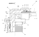
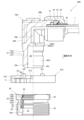
- FIG. 1 is a vertical cross-sectional view cut in half of a pipe joint unit equipped with an anti-rotation member according to a first embodiment, showing a state before an adapter and a body are connected to each other.
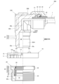
- FIG. FIG. 4 is a vertical cross-sectional view cut in half showing a state in which the adapter and the body are connected to each other.
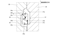
- 3 is an enlarged cross-sectional view of part A in FIG. 2 , showing the behavior of the elastic ring member, illustrating a state in which an upper outer peripheral corner of the elastic ring member comes into contact with a second tapered surface of the first engagement groove.
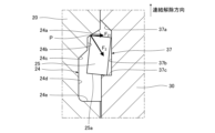
- 3 is an enlarged cross-sectional view of part A in FIG. 2 , showing the behavior of the elastic ring member, in a tilted state.
- FIG. 3 is an enlarged cross-sectional view of part A in FIG. 2 , showing the behavior of the elastic ring member, illustrating a state in which an upper outer peripheral corner of the elastic ring member comes into contact with a first tapered surface of a first engagement groove.
- 3 is an enlarged cross-sectional view of part A in FIG. 2, showing the behavior of the elastic ring member, illustrating a state in which a tapered surface is formed on the outer periphery of the upper end of the elastic ring member;
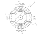
- FIG. 3 is a cross-sectional view taken along line BB shown in FIG. 2.
- 3 is a cross-sectional view taken along line CC shown in FIG. 2.
- 3 is a cross-sectional view taken along line DD shown in FIG. 2.
- FIG. 3 is a vertical cross-sectional view cut in half, showing a state in which the anti-rotation member has been moved to its limit in the upward direction in the figure, and corresponds to FIG. 2 .
- 8 is a view of the anti-rotation member as viewed in the direction of arrow E shown in FIG. 7 .
- 13 is a vertical cross-sectional view cut in half of a pipe joint unit equipped with an anti-rotation member according to a second embodiment, showing a state in which an adapter and a body are connected.
- FIG. 10 is a cross-sectional view taken along line FF shown in FIG. 9.
- FIG. 13 is a vertical cross-sectional view cut in half of a pipe joint unit provided with an anti-rotation member according to a third embodiment, showing a state before an adapter and a body are connected to each other.
- FIG. 13 is a cross-sectional view of a main portion of a pipe joint unit including an anti-rotation member according to a fourth embodiment, the cross-sectional view corresponding to FIG. 5 .
- 13 is a cross-sectional view of a main portion of a pipe joint unit including an anti-rotation member according to a fourth embodiment, the cross-sectional view corresponding to FIG. 6 .
- FIG. 13 is a vertical cross-sectional view cut in half of a pipe joint unit provided with an anti-rotation member according to a fifth embodiment, showing a state before an adapter and a body are connected to each other.
- FIG. 13 is a cross-sectional view of a main portion of a pipe joint unit including an anti-rotation member according to a fifth embodiment, the cross-sectional view corresponding to FIG. 6 .
- 13 is a cross-sectional view of a main portion of a pipe joint unit including an anti-rotation member according to a fifth embodiment when pressurized with air, the cross-sectional view corresponding to FIG. 6.
- FIG. 13 is a vertical cross-sectional view cut in half of a pipe joint unit provided with an anti-rotation member according to a sixth embodiment, showing a state before an adapter and a body are connected to each other.
- FIG. 13 is a cross-sectional view of a main portion of a pipe joint unit including an anti-rotation member according to a sixth embodiment, the cross-sectional view corresponding to FIG. 6.
- 13 is a cross-sectional view of a main portion of a pipe joint unit including an anti-rotation member according to a sixth embodiment when pressurized with air, the view corresponding to FIG. 6.
- FIG. 13 is a vertical cross-sectional view cut in half of a pipe joint unit equipped with an anti-rotation member according to a seventh embodiment, showing the state before the adapter and the body are connected to each other.
- FIG. 19 is a cross-sectional view of a main portion of a pipe joint unit including an anti-rotation member according to a seventh embodiment, the cross-sectional view corresponding to FIG. 18 .
- FIG. 13 is a cross-sectional view of a main part immediately before the anti-rotation member according to the seventh embodiment is fitted from above the pipe joint unit.
- FIG. 1 is a half-cut longitudinal sectional view of a pipe joint unit 100 including an anti-rotation member 10 according to this embodiment.
- the pipe joint unit 100 of this embodiment includes an adapter 20, which is a female member made of metal, and a body 30, which is a male member made of resin.
- the adapter 20 and the body 30 are used by being connected to each other.
- the adapter 20 and the body 30 are also called a pipe joint.
- FIG. 1 shows a state before the adapter 20 and the body 30 are connected.
- the adapter 20 and the body 30 are connected by moving the body 30 downward in FIG. 1 from the state shown in FIG. 1 and inserting it into the adapter 20.
- the downward direction in FIG. 1 is also referred to as the "connection direction.”
- the pipe joint unit 100 can be used for air piping, such as air brake piping for vehicles such as trucks.
- the adapter 20 is connected to equipment such as an air tank, and the body 30 is connected to a tubular member such as a tube.
- a tool such as a torque driver, it is possible to attach multiple bodies 30 to the equipment without interfering with each other, even with a narrow pitch.
- the adapter 20 is made of a lead-containing copper-zinc alloy (C3604), and the body 30 is made of polyamide 12 (PA12) reinforced with glass fiber (GF). These materials are merely examples, and the present invention is not limited to these.
- the adapter 20 can be made of a material such as brass, lead-free material such as C6801, aluminum alloy, steel material, or stainless steel.
- the adapter 20 may be made of resin.
- the body 30 can be made of a resin material such as polyamide 66 (PA66), polyamide 12 (PA12), polyacetal (POM), or polybutylene terephthalate (PBT), or metal materials such as brass forgings (C3771), lead-free brass, aluminum alloy, or stainless steel alloy.
- the adapter 20 is a cylindrical member, and a circular hole 20a is formed in the center of the shaft. A flow path 21 is formed by the circular hole 20a.
- a nut portion 22 is formed at the top of the adapter 20 in FIG. 1.
- a threaded portion 23 is formed on the outer periphery below the nut portion 22.
- An O-ring (not shown) is provided between the nut portion 22 and the threaded portion 23.
- the adapter 20 can be attached to the device by turning the nut portion 22 using a tool (not shown), such as a spanner or wrench, to screw the threaded portion 23 into a screw hole of the device (not shown).
- the shape of the threaded portion 23 shown in FIG. 1 is one example, and the present invention is not limited to this.
- the shape of the threaded portion 23 may be a tapered thread, a parallel thread and a seal material, a metal seal, or the like.
- the threaded portion 23 may also be a female thread.
- a first locking groove 24 is formed on the inner circumference of the circular hole 20a of the adapter 20.
- the first locking groove 24 is formed around the entire circumference of the circular hole 20a of the adapter 20.
- the first locking groove 24 includes a first tapered surface 24a, a first parallel surface 24b, a second tapered surface 24c, a second parallel surface 24d, and an orthogonal surface 24e.
- the first tapered surface 24a, the first parallel surface 24b, the second tapered surface 24c, the second parallel surface 24d, and the orthogonal surface 24e are provided in this order in the connection direction.
- the first tapered surface 24a is inclined with respect to the axis of the adapter 20 so as to increase in diameter as it proceeds in the connection direction.
- the first parallel surface 24b is approximately parallel to the axis of the adapter 20.
- the second tapered surface 24c is inclined with respect to the axis of the adapter 20 so as to increase in diameter as it proceeds in the connection direction.
- the second parallel surface 24d is approximately parallel to the axis of the adapter 20.
- the orthogonal surface 24e is approximately perpendicular to the axis of the adapter 20.
- the circular hole 20a of the adapter 20 is formed with a first tapered surface 24a and a second tapered surface 24c that are two stages in diameter that increase in diameter as they proceed in the connection direction, and the first parallel surface 24b connects the first tapered surface 24a and the second tapered surface 24c, and the second parallel surface 24d connects the second tapered surface 24c and the orthogonal surface 24e.
- the elastic ring member 25 is fitted and held in the first locking groove 24.
- the elastic ring member 25 is, for example, a C-ring with a part of the outer circumference cut out so that the diameter can be expanded or contracted.
- the elastic ring member 25 may be made of resin (for example, polyamide 12 (PA12) reinforced with glass fiber (GF), which is the same material as the body 30) or metal.
- the vertical cross section of the elastic ring member 25 is, for example, rectangular.
- the inner peripheral surface of the elastic ring member 25 protrudes from the inner peripheral surface of the circular hole 20a of the adapter 20, and a gap is formed between the outer peripheral surface of the elastic ring member 25 and the second parallel surface 24d of the first locking groove 24.
- a ring groove 26 is formed on the inner circumference of the circular hole 20a of the adapter 20.
- a seal member 27 is fitted into the ring groove 26.
- the seal member 27 is, for example, an O-ring.
- the seal member 27 can be made of, for example, ethylene propylene diene rubber (EPDM), acrylonitrile butadiene rubber (NBR), or hydrogenated nitrile rubber (HNBR).
- a sealing member 28 for preventing the inflow of dirt is provided above the first engagement groove 24 in FIG. 1.
- the sealing member 28 is, for example, an O-ring.
- the sealing member 28 can be made of, for example, ethylene propylene diene rubber (EPDM), acrylonitrile butadiene rubber (NBR), or hydrogenated nitrile rubber (HNBR).
- the body 30 is a cylindrical member bent in a horizontal L-shape, and includes a vertical section 30A extending along the connecting direction, and a horizontal section 30B bent at a right angle from the upper end of the vertical section 30A and extending horizontally as one unit.
- a flow path 36 bent in a horizontal L-shape is provided inside the body 30 by circular holes 30a and 30b of different diameters.
- the body 30 is constructed from a member bent in a horizontal L-shape, but the body 30 may also be constructed from an F-, T-, or Y-shaped member.
- a seal ring 31, a buckling ring 32, a locking ring 33, a cap 34, and a release ring 35 are provided at the open end of the horizontal section 30B.
- the seal ring 31, the buckling ring 32, the locking ring 33, the cap 34, and the release ring 35 hold the tube 1 in the body 30.
- the flow path 36 is continuous with the internal space of the tube 1, and fluid can flow between the flow path 36 and the internal space of the tube 1.
- a flange portion 30C is integrally formed at the mid-height position of the outer periphery of the vertical portion 30A of the body 30.
- the portion on the connection direction side of the flange portion 30C constitutes the insertion portion 30A1 that is inserted into the circular hole 20a of the adapter 20.
- a tapered surface 30c that reduces in diameter as it approaches the connection direction is formed on the outer periphery of the lower end of the insertion portion 30A1.
- a second locking groove 37 is formed around the entire outer periphery of the insertion portion 30A1.
- the second locking groove 37 includes a tapered surface 37a, a parallel surface 37b, and an orthogonal surface 37c.
- the tapered surface 37a, the parallel surface 37b, and the orthogonal surface 37c are arranged in this order in the connection direction.
- the tapered surface 37a is inclined with respect to the axis of the vertical portion 30A so that the diameter decreases toward the connection direction.
- the parallel surface 37b is approximately parallel to the axis of the vertical portion 30A.
- the orthogonal surface 37c is approximately orthogonal to the axis of the vertical portion 30A.
- the insertion portion 30A1 is formed with a one-stage tapered surface 37a that decreases in diameter toward the connection direction, and the parallel surface 37b connects the tapered surface 37a and the orthogonal surface 37c.
- Figure 2 is a half-cut vertical cross-sectional view showing the adapter 20 and the body 30 connected together.
- the adapter 20 and the body 30 are connected together by inserting the body 30 into the adapter 20 in the connection direction from the state shown in Figure 1.
- the tapered surface 30c of the insertion portion 30A1 abuts against the inner peripheral edge of the upper end of the elastic ring member 25 that is fitted and held in the first locking groove 24 of the adapter 20.
- the elastic ring member 25 is pushed outward in the radial direction of the adapter 20 by the insertion portion 30A1, expanding in diameter.
- the elastic ring member 25 then sinks into the first locking groove 24, allowing the body 30 to pass through (be pushed in).
- the force expanding the diameter of the elastic ring member 25 is released.
- the elastic ring member 25 contracts in diameter due to its own elastic restoring force, returning to its initial state, and is locked into the second locking groove 37 of the body 30.
- the elastic ring member 25 is provided across the second locking groove 37 of the body 30 and the first locking groove 24 of the adapter 20.
- the body 30 and the adapter 20 are connected via the elastic ring member 25 by the simple operation of simply inserting the body 30 into the adapter 20. Therefore, for example, in the limited space inside the bonnet of a truck, the body 30 can be attached to the adapter 20 with good workability while preventing interference between multiple bodies 30.
- Figures 3A to 3D are enlarged cross-sectional views of part A in Figure 2, showing the behavior of the elastic ring member 25.
- the elastic ring member 25 When no fluid pressure is acting on the adapter 20 and the body 30, the elastic ring member 25 is in the state shown in Figure 2.
- fluid pressure is acting on the adapter 20 and the body 30, that is, when high-pressure air, for example, flows through the flow path 36 of the body 30, the body 30 receives a force in a direction that causes it to come out of the adapter 20 (upward in Figure 2, also called the "disconnection direction").
- the body 30 moves in the disconnection direction until the upper outer circumferential corner P of the elastic ring member 25 comes into contact with the second tapered surface 24c of the first locking groove 24.
- Figure 3A shows the state in which the upper outer circumferential corner P of the elastic ring member 25 comes into contact with the second tapered surface 24c of the first locking groove 24.
- a force F1 acts from the second tapered surface 24c to the elastic ring member 25.
- the force F1 is a force in a direction perpendicular to the second tapered surface 24c.
- the bottom surface 25a of the elastic ring member 25 is in surface contact with the orthogonal surface 37c of the second locking groove 37 of the body 30. Therefore, a resistance force N acts on the elastic ring member 25.
- the resistance force N is a force perpendicular to the orthogonal surface 37c.
- a friction force F F acts on the bottom surface 25a of the elastic ring member 25.
- the magnitude of the friction force F F is a value obtained by multiplying the friction coefficient between the bottom surface 25a of the elastic ring member 25 and the orthogonal surface 37c of the second locking groove 37 by the magnitude of the resistance force N.
- a couple force M acts on the elastic ring member 25.
- the elastic ring member 25 tilts as shown in Fig. 3B.
- Fig. 3B shows the elastic ring member 25 in a tilted state.
- the outer peripheral corner portion P of the upper end of the elastic ring member 25 is displaced radially inward of the adapter 20 beyond the first parallel surface 24b, and comes off the second tapered surface 24c of the first locking groove 24.
- the elastic ring member 25 functions as a movement limit setting member that determines the movement limit of the body 30 relative to the adapter 20 in the disconnection direction that releases the connection between the adapter 20 and the body 30.
- the elastic ring member 25 limits the movement of the body 30 in the disconnection direction, preventing the body 30 from moving any further in the disconnection direction, that is, preventing the body 30 from coming off the adapter 20 and becoming disconnected.
- a force F2 acts on the elastic ring member 25 from the first tapered surface 24a.
- the force F2 is a force perpendicular to the first tapered surface 24a.
- the horizontal component F21 of the force F2 causes the elastic ring member 25 to contract in diameter, and the inner peripheral surface of the elastic ring member 25 is pressed against the parallel surface 37b of the second locking groove 37 of the body 30. Therefore, the engagement allowance (hanging allowance) between the elastic ring member 25 and the orthogonal surface 37c of the second locking groove 37 becomes larger than the engagement allowance shown in FIG. 3A, which further prevents the body 30 from slipping off the adapter 20 and being released from the connection.
- FIG. 3D shows a state in which a tapered surface 25b is formed on the outer periphery of the upper end of the elastic ring member 25.
- the outer periphery corner P of the upper end of the elastic ring member 25 may be scraped by rubbing against the second tapered surface 24c of the first locking groove 24, forming the tapered surface 25b.
- the elastic ring member 25 is pressed in the diameter-reducing direction by the horizontal component force F31 of the force F3 perpendicular to the first tapered surface 24a of the first locking groove 24.
- the elastic ring member 25 is pressed against the parallel surface 37b of the second locking groove 37, so that the engagement allowance (hanging allowance) between the elastic ring member 25 and the orthogonal surface 37c of the second locking groove 37 is sufficiently secured. Therefore, even when fluid pressure is applied to the body 30, the body 30 is prevented from coming off the adapter 20.
- the elastic ring member 25 has a rectangular cross section, but the cross section of the elastic ring member 25 may have another shape.
- the cross section of the elastic ring member 25 may have a rectangular shape with the upper outer corner cut at an angle, a rectangular shape with the upper and lower outer corners cut at an angle, a rectangular shape with the upper inner corner cut at an angle, a rectangular shape with the upper outer corner cut at an angle and the upper inner corner cut at an angle, a rectangular shape with the lower outer corner cut at an angle and the upper inner corner cut at an angle, or a rectangular shape with the upper outer corner, lower outer corner, and upper inner corner cut at an angle.
- the pipe fitting unit 100 further includes an anti-rotation member 10 that prevents relative rotation between the adapter 20 and the body 30, which are connected to each other.
- the anti-rotation member 10 like the body 30, is made of polyamide 66 (PA66) reinforced with glass fiber (GF). This material is an example, and the present invention is not limited to this.
- the material constituting the anti-rotation member 10 may be a resin material such as polyamide 66 (PA66), polyamide 12 (PA12), polyacetal (POM), polybutylene terephthalate (PBT), or a metal material such as brass forging (C3771), lead-free brass, aluminum alloy, or stainless steel alloy.
- the anti-rotation member 10 has a first fitting portion 11 formed to be able to fit with the nut portion 22 of the adapter 20, and a second fitting portion 12 connected to the first fitting portion 11. As shown in FIG. 2, when the body 30 is connected to the adapter 20 and the first fitting portion 11 is fitted with the nut portion 22 of the adapter 20, the second fitting portion 12 fits with the flange portion 30C of the body 30.
- Figure 4 is a cross-sectional view taken along line B-B in Figure 2.
- the nut portion 22 is a so-called hexagonal nut, and the outer peripheral surface of the nut portion 22 includes six flat surfaces 22a positioned in a ring shape around the axis of the adapter 20, and curved portions 22b connecting adjacent flat surfaces 22a.
- the nut portion 22 may not have curved portions 22b, and adjacent flat surfaces 22a may be connected via intersections or edges.
- the first fitting portion 11 of the anti-rotation member 10 accommodates the nut portion 22 of the adapter 20 and fits onto the outer periphery of the nut portion 22.
- the axial center of the first fitting portion 11 approximately coincides with the axial center of the nut portion 22.
- a plurality of teeth 11a are formed on the inner periphery of the first fitting portion 11 and are arranged in a ring shape around the axis of the first fitting portion 11.
- the curved portion 22b of the nut portion 22 is disposed between adjacent teeth 11a.
- the engagement between the first fitting portion 11 and the nut portion 22 may be such that there is no gap between the first fitting portion 11 and the nut portion 22, or such that there is a certain amount of gap between the first fitting portion 11 and the nut portion 22.
- the number of teeth 11a of the first fitting portion 11 is greater than the number of curved portions 22b of the nut portion 22.
- the nut portion 22 has six curved portions 22b, whereas the first fitting portion 11 has 18 teeth 11a. Therefore, the first fitting portion 11 and the nut portion 22 can be fitted together by changing the orientation of the first fitting portion 11 relative to the nut portion 22.
- the shapes of the first fitting portion 11 and the nut portion 22 are not limited to the example shown in FIG. 4, but it is preferable that the number of teeth 11a is a natural number multiple of the number of curved portions 22b.
- FIG. 5 is a cross-sectional view taken along line C-C in FIG. 2.
- the outer periphery of the flange portion 30C of the body 30 is formed in a non-circular shape.
- the outer periphery of the flange portion 30C includes a pair of arcuate surfaces 30C1 located on opposite sides of the body 30 in the radial direction and centered on the axis of the body 30, and a pair of connecting surfaces 30C2 that connect the ends of the pair of arcuate surfaces 30C1.
- the connecting surfaces 30C2 include multiple flat surfaces and multiple curved portions.
- the second fitting portion 12 of the rotation prevention member 10 protrudes inward in the radial direction from the first fitting portion 11 in an annular shape.
- the second fitting portion 12 accommodates the flange portion 30C and fits to the outer periphery of the flange portion 30C.
- the axial center of the second fitting portion 12 approximately coincides with the axial center of the flange portion 30C.
- the inner periphery of the second fitting portion 12 has a shape corresponding to the outer periphery of the flange portion 30C and is formed in a non-circular shape.
- the inner periphery of the second fitting portion 12 includes a pair of arc surfaces 12a located on opposite sides of the second fitting portion 12 in the radial direction and centered on the axis of the second fitting portion 12, and a pair of connecting surfaces 12b connecting the ends of the pair of arc surfaces 12a.
- the connecting surfaces 12b include multiple flat surfaces and multiple curved portions.
- connection surface 12b of the second fitting portion 12 and the connection surface 30C2 of the flange portion 30C come into contact with each other. Therefore, when the second fitting portion 12 and the flange portion 30C are fitted together, the second fitting portion 12 cannot rotate relative to the body 30.
- the fit between the second fitting portion 12 and the flange portion 30C may be such that there is no gap at all between the second fitting portion 12 and the flange portion 30C, or such that there is a certain amount of gap between the second fitting portion 12 and the flange portion 30C.
- FIG. 6 is a cross-sectional view taken along line D-D in FIG. 2.
- a recess 30C3 is formed in the arc surface 30C1 of the flange portion 30C of the body 30.
- the recess 30C3 is formed partially on the arc surface 30C1 in the axial direction of the body 30.
- a protrusion 13 is formed on the arc surface 12a of the second fitting portion 12 of the rotation prevention member 10, which is inserted into and hooked onto the recess 30C3 of the flange portion 30C.
- the protrusion 13 When the protrusion 13 is hooked onto the recess 30C3, the relative movement between the body 30 and the second fitting portion 12 in the axial direction of the body 30 is restricted.
- the protrusion 13 functions as a restricting portion that restricts the relative movement between the body 30 and the second fitting portion 12 in the axial direction of the body 30.
- the recess 30C3 of the flange portion 30C and the protrusion 13 of the anti-rotation member 10 restrict the relative movement between the body 30 and the second fitting portion 12 in the axial direction of the body 30, so that when the body 30 moves in the axial direction, the second fitting portion 12 moves with the body 30. This prevents the second fitting portion 12 from being disengaged from the flange portion 30C, and more reliably prevents the relative rotation between the adapter 20 and the body 30.
- the second fitting portion 12 has a through hole 12c located radially away from the protrusion 13 of the body 30. Therefore, the inner portion 12d of the second fitting portion 12 located radially inside the body 30 from the through hole 12c is easily deformed compared to the case where the through hole 12c is not present.
- the top and bottom of the protrusion 13 and the recess 30C3 are tapered. Therefore, when the rotation prevention member 10 is moved upward, the tapered portions come into contact with each other and the inner portion 12d is pushed outward in the radial direction of the body 30.
- the protrusion 13 can be easily displaced in the radial direction of the body 30 without extending the second fitting portion 12 in the axial direction of the body 30, and the protrusion 13 can be easily removed from the recess 30C3 of the flange portion 30C. This allows the restriction on the relative movement between the body 30 and the second fitting portion 12 to be released, and a rotation prevention member 10 that is small and easy to attach and detach to the body 30 can be provided.
- the through hole 12c is located inside the first fitting portion 11 when the anti-rotation member 10 is viewed in the axial direction of the first fitting portion 11.
- the outer portion 12e of the second fitting portion 12 which is located radially outside the body 30 from the through hole 12c, reduces deformation of the second fitting portion 12 in the direction in which the distance between the pair of connection surfaces 12b increases. This makes it possible to prevent rattling from increasing when the second fitting portion 12 and the flange portion 30C are fitted together.
- the anti-rotation member 10 is provided with a guide 12h that protrudes from the second fitting portion 12 in the direction opposite to the connection direction.
- Figure 7 is a half-section vertical cross-sectional view showing the state in which the anti-rotation member 10 has been moved to its limit toward the top of the figure, and is shown corresponding to Figure 2.
- the nut portion 22 of the adapter 20 has come out of the first fitting portion 11 of the anti-rotation member 10, and the fitting between the nut portion 22 and the first fitting portion 11 is released.
- This allows the orientation of the anti-rotation member 10 relative to the adapter 20 to be changed, and the orientation of the body 30 relative to the adapter 20 to be changed.
- the movement of the anti-rotation member 10 in the disconnection direction and the rotation of the body 30 and the anti-rotation member 10 relative to the adapter 20 are performed, for example, manually.
- the second fitting portion 12 of the anti-rotation member 10 has an opposing surface 12f that faces the horizontal portion 30B and cap 34 of the body 30 in the axial direction of the body 30.
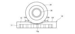
- FIG. 8 is a view of the anti-rotation member 10 viewed in the direction of arrow E shown in FIG. 7. Note that the tube 1 is not shown in FIG. 8. As shown in FIGS. 2 and 8, a recess 12g is formed in the opposing surface 12f. Therefore, the horizontal portion 30B and cap 34 can be brought closer to the adapter 20 without interfering with the second fitting portion 12, and the pipe fitting unit 100 can be made smaller.
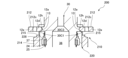
- Second Embodiment 9 is a half-cut vertical cross-sectional view of a pipe joint unit 200 equipped with an anti-rotation member 210 according to this embodiment, showing a state in which an adapter 220 is connected to a body 30.
- differences from the first embodiment will be mainly described, and configurations that are the same as or equivalent to those described in the first embodiment will be denoted by the same reference numerals in the drawing and description thereof will be omitted.
- a flow path 221 formed by large and small circular holes 220a, 220b of different diameters is provided through the axial center of the adapter 220, which is the female member.
- the nut portion 22 is provided at a middle height position in the vertical direction of the adapter 220 in FIG. 9, and a cylindrical portion 228 is provided above the nut portion 22.
- the first locking groove 24 and the ring groove 26 are formed on the inner circumference of the large diameter circular hole 220a of the adapter 220.
- the anti-rotation member 210 further includes a connection portion 214 that connects the first fitting portion 11 and the second fitting portion 212.
- the connection portion 214 is formed in a cylindrical shape and accommodates the cylindrical portion 228 of the adapter 220.
- the second fitting portion 212 protrudes radially outward from the connection portion 214 in an annular shape.
- the second fitting portion 212 has a through hole 212c located radially away from the protrusion 13 in the body 30.
- the connection portion 214 has a through hole 215 below the inner portion 12d of the second fitting portion 212 located radially inside the body 30 relative to the through hole 212c. Therefore, the inner portion 12d of the second fitting portion 212 is easily displaced compared to the case where there is no through hole 215.
- the upper and lower portions of the protrusion 13 and the recess 30C3 are tapered.
- the rotation prevention member 210 when the rotation prevention member 210 is moved upward, the tapered portions come into contact with each other and the inner portion 12d is pushed outward in the radial direction of the body 30. Therefore, the protrusion 13 can be easily displaced radially of the body 30, and the protrusion 13 can be easily removed from the recess 30C3. This makes it possible to remove restrictions on the relative movement between the body 30 and the second fitting portion 212, and to provide a small anti-rotation member 210 that is easy to attach and detach from the body 30.
- the rest of the configuration of the pipe fitting unit 200 is the same as the configuration of the pipe fitting unit 100 according to the first embodiment (see FIG. 1, etc.).
- the basic configuration of the anti-rotation member 210 and pipe joint unit 200 according to this embodiment configured as described above is the same as that of the anti-rotation member 10 and pipe joint unit 100 according to the first embodiment (see FIG. 1, etc.), so the anti-rotation member 210 and pipe joint unit 200 according to this embodiment also provide the same effects as those obtained in the first embodiment.
- Third Embodiment 11 is a half-cut vertical cross-sectional view of a pipe joint unit 300 equipped with an anti-rotation member 310 according to this embodiment, showing the state before the adapter 320 and the body 330 are connected.
- differences from the first embodiment will be mainly described, and the same or corresponding configurations as those described in the first embodiment will be denoted by the same reference numerals in the drawing and description thereof will be omitted.
- the female and male members are reversed compared to the pipe fitting unit 100 according to the first embodiment (see FIG. 1, etc.). That is, the adapter 320 is the male member, and the body 330 is the female member. The adapter 320 is inserted into the body 330 to connect the adapter 320 and the body 330.
- a circular hole 330a is formed in the vertical portion 330A of the body 330, and a first locking groove 334 and a ring groove 336 are formed on the inner circumference of the circular hole 330a.
- the first locking groove 334 is formed in a two-stage tapered shape that narrows in diameter toward the bottom (connection direction) in FIG. 11, similar to the first locking groove 24 in the first embodiment (see FIG. 1, etc.).
- An elastic ring member 335 is fitted and held in the first locking groove 334.
- a seal member 337 is fitted into the ring groove 336.
- a nut portion 22 is integrally formed at the mid-height position on the outer periphery of the adapter 320.
- the portion above the nut portion 22 constitutes the insertion portion 320A1 that is inserted into the circular hole 330a of the body 330.
- a tapered surface 320c that expands in diameter downward (in the connection direction) is formed on the outer periphery of the upper end of the insertion portion 320A1.
- a second locking groove 327 is formed around the entire periphery of the insertion portion 320A1.
- the second locking groove 327 is formed in a single taper shape that expands in diameter toward the bottom (connection direction) in FIG. 11, similar to the second locking groove 37 in the first embodiment (see FIG. 1, etc.).
- the elastic ring member 335 is provided across the second locking groove 327 of the adapter 320 and the first locking groove 334 of the body 330 when the adapter 320 is inserted into the body 330 until the second locking groove 327 of the adapter 320 matches the first locking groove 334 of the body 330.
- the rest of the configuration of the pipe fitting unit 300 is the same as the configuration of the pipe fitting unit 100 according to the first embodiment (see FIG. 1, etc.).
- the basic configuration of the anti-rotation member 310 and pipe joint unit 300 according to this embodiment configured as described above is the same as that of the anti-rotation member 10 and pipe joint unit 100 according to the first embodiment (see FIG. 1, etc.), so the anti-rotation member 310 and pipe joint unit 300 according to this embodiment also provide the same effects as those obtained in the first embodiment.
- connection portion 214 (see FIG. 9) of the adapter 220 in the second embodiment may be provided below the flange portion 330C, and the connection portion 214 (see FIG. 9) of the anti-rotation member 210 in the second embodiment may be provided on the anti-rotation member 310.
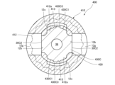
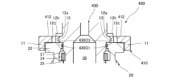
- Figure 12 is a cross-sectional view of a main part of a pipe joint unit 400 including an anti-rotation member 410 according to this embodiment, and is shown corresponding to Figure 5.
- Figure 13 is a cross-sectional view of a main part of a pipe joint unit 400 including an anti-rotation member 410 according to this embodiment, and is shown corresponding to Figure 6.
- the recess 30C3 of the body 30 and the protrusion 13 of the anti-rotation member 10 are reversed compared to the pipe fitting unit 100 according to the first embodiment (see FIG. 1, etc.). That is, the protrusion 430C3 is formed on the arc surface 430C1 of the flange portion 430C of the body 430.
- the recess 413 into which the protrusion 430C3 of the flange portion 430C is inserted and hooked is formed on the arc surface 412a of the second fitting portion 412 of the anti-rotation member 410.
- the recess 413 When the recess 413 is hooked onto the protrusion 430C3, the relative movement between the body 430 and the second fitting portion 412 in the axial direction of the body 430 is restricted.
- the recess 413 functions as a restricting portion that restricts the relative movement between the body 430 and the second fitting portion 412 in the axial direction of the body 430.
- the rest of the configuration of the pipe fitting unit 400 is the same as the configuration of the pipe fitting unit 100 according to the first embodiment (see FIG. 1, etc.).
- the basic configuration of the anti-rotation member 410 and pipe joint unit 400 according to this embodiment configured as described above is the same as that of the anti-rotation member 10 and pipe joint unit 100 according to the first embodiment (see FIG. 1, etc.), so the anti-rotation member 410 and pipe joint unit 400 according to this embodiment also provide the same effects as those obtained in the first embodiment.
- Fig. 14 is a vertical cross-sectional view cut in half of a pipe joint unit 500 including a rotation prevention member 510 according to this embodiment, showing a state before the adapter 20 and the body 530 are connected.
- Fig. 15 is a cross-sectional view of a main part of the pipe joint unit 500 including the rotation prevention member 510 according to this embodiment, shown in correspondence with Fig. 6.
- Fig. 16 is a cross-sectional view of a main part of the pipe joint unit 500 including the rotation prevention member 510 according to this embodiment when pressurized with air, shown in correspondence with Fig. 6.
- differences from the first embodiment will be mainly described, and the same or corresponding configurations as those described in the first embodiment will be denoted by the same reference numerals as those in the first embodiment, and description thereof will be omitted.
- the recess 530C3 of the body 530 is formed from the vertical middle to the bottom end of the flange portion 530C.
- the protrusion 513 of the rotation prevention member 510 is formed from the vertical middle to the bottom end of the second fitting portion 512.
- the convex portion 513 of the anti-rotation member 510 fits into the concave portion 530C3 of the body 530. Because the inner diameter of the convex portion 513 and the outer diameter of the concave portion 530C3 are approximately the same, there is no need to recess the convex portion 513 radially outward, and the anti-rotation member 510 can be easily fitted into the body 530. If only the anti-rotation member 510 shifts upward, the convex portion 513 acts as a stopper, preventing only the anti-rotation member 510 from coming off.
- the body 530 moves in the opposite direction to the connection direction.
- the anti-rotation member 510 remains on the adapter 20, and the engagement length between the convex portion 513 of the anti-rotation member 510 and the concave portion 530C3 of the body 530 becomes shorter.
- the anti-rotation member 510 is provided with a guide 12h that protrudes from the second engagement portion 512 in the opposite direction to the connection direction, and the engagement allowance between the anti-rotation member 510 and the body 530 can be secured by the guide 12h.
- the rest of the configuration of the pipe fitting unit 500 is the same as the configuration of the pipe fitting unit 100 according to the first embodiment (see FIG. 1, etc.).
- the recess 530C3 and the protrusion 513 are also applicable to the second to fourth embodiments.
- the basic configuration of the anti-rotation member 510 and pipe joint unit 500 of this embodiment configured as described above is the same as that of the anti-rotation member 10 and pipe joint unit 100 of the first embodiment (see FIG. 1, etc.), so the anti-rotation member 510 and pipe joint unit 500 of this embodiment also provide the same effects as those obtained in the first embodiment.
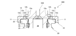
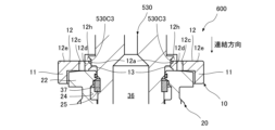
- Fig. 17 is a vertical cross-sectional view cut in half of a pipe joint unit 600 including the anti-rotation member 10 according to this embodiment, showing the state before the adapter 20 and the body 530 are connected.
- Fig. 18 is a cross-sectional view of the main parts of the pipe joint unit 600 including the anti-rotation member 10 according to this embodiment, shown in correspondence with Fig. 6.
- Fig. 19 is a cross-sectional view of the main parts of the pipe joint unit 600 including the anti-rotation member 10 according to this embodiment when pressurized with air, shown in correspondence with Fig. 6.
- differences from the fifth embodiment will be mainly described, and the same or corresponding configurations as those described in the fifth embodiment will be denoted by the same reference numerals as those in the fifth embodiment, and description thereof will be omitted.
- the recess 530C3 of the body 530 is formed from the vertical middle to the bottom end of the flange portion 530C.
- the anti-rotation member 10 can be easily fitted to the body 530. If only the anti-rotation member 10 shifts upward, the protrusion 13 acts as a stopper, preventing only the anti-rotation member 10 from coming off.
- the length of the convex portion 13 in the vertical direction is shorter than in the fifth embodiment, so the length over which it must overcome the arc surface 12a above the concave portion 530C3 is short. Therefore, the anti-rotation member 10 can be easily disengaged from the body 530, and the angle between the adapter 20 and the body 530 can be easily changed.
- the body 530 moves in the opposite direction to the connection direction.
- the anti-rotation member 10 remains on the adapter 20, and the engagement length between the convex portion 13 of the anti-rotation member 10 and the concave portion 530C3 of the body 530 becomes shorter.
- the anti-rotation member 10 is provided with a guide 12h that protrudes from the second engagement portion 12 in the opposite direction to the connection direction, and the engagement allowance between the anti-rotation member 10 and the body 530 can be secured by the guide 12h.
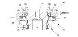
- Fig. 20 is a vertical cross-sectional view cut in half of a pipe joint unit 700 equipped with the anti-rotation member 10 according to this embodiment, showing the state before the adapter 20 and the body 730 are connected.
- the body 730 is provided with a rib 738 that protrudes from the flange portion 730C in the opposite direction to the connection direction.
- Fig. 21 is a cross-sectional view of the main parts of the pipe joint unit 700 equipped with the anti-rotation member 10 according to this embodiment, shown in correspondence with Fig. 18.
- Fig. 22 is a cross-sectional view of the main parts immediately before the anti-rotation member 10 according to this embodiment is fitted from above the pipe joint unit 700.
- the rib 738 provided on the body 730 of the seventh embodiment may be applied to the bodies 30, 330, and 530 of the first to fifth embodiments.
- the bodies 30, 330, and 530 may be provided with ribs that protrude from the flange portions 30C, 330C, and 530C in the direction opposite to the connection direction.
Landscapes
- Engineering & Computer Science (AREA)
- General Engineering & Computer Science (AREA)
- Mechanical Engineering (AREA)
- Quick-Acting Or Multi-Walled Pipe Joints (AREA)
Abstract
Description
図1は、本実施形態に係る回転防止部材10を備えた管継手ユニット100の半裁縦断面図である。図1に示すように、本実施形態の管継手ユニット100は、金属製の雌部材であるアダプタ20と、樹脂製の雄部材であるボディ30と、を備えている。アダプタ20とボディ30は、互いに連結されて用いられる。アダプタ20とボディ30とは、管継手とも呼ばれる。なお、図1では、アダプタ20とボディ30とを連結する前の状態を示している。図1に示す状態からボディ30を図1における下方に移動させてアダプタ20に差し込むことにより、アダプタ20とボディ30が連結される。以下において、図1における下方を「連結方向」とも称する。
図9は、本実施形態に係る回転防止部材210を備えた管継手ユニット200の半裁縦断面図であり、アダプタ220とボディ30とを連結した状態を示す。以下では、第1実施形態との相違点を主に説明し、第1実施形態で説明した構成と同一の構成又は相当する構成については、図中に第1実施形態と同一の符号を付して説明を省略する。
図11は、本実施形態に係る回転防止部材310を備えた管継手ユニット300の半裁縦断面図であり、アダプタ320とボディ330とを連結する前の状態を示す。以下では、第1実施形態との相違点を主に説明し、第1実施形態で説明した構成と同一の構成又は相当する構成については、図中に第1実施形態と同一の符号を付して説明を省略する。
図12は、本実施形態に係る回転防止部材410を備える管継手ユニット400の要部の断面図であり、図5に対応して示す。図13は、本実施形態に係る回転防止部材410を備える管継手ユニット400の要部の断面図であり、図6に対応して示す。以下では、第1実施形態との相違点を主に説明し、第1実施形態で説明した構成と同一の構成又は相当する構成については、図中に第1実施形態と同一の符号を付して説明を省略する。
図14は、本実施形態に係る回転防止部材510を備えた管継手ユニット500の半裁縦断面図であり、アダプタ20とボディ530とを連結する前の状態を示す。図15は、本実施形態に係る回転防止部材510を備える管継手ユニット500の要部の断面図であり、図6に対応して示す。図16は、本実施形態に係る回転防止部材510を備える管継手ユニット500がエアで加圧された場合の要部の断面図であり、図6に対応して示す。以下では、第1実施形態との相違点を主に説明し、第1実施形態で説明した構成と同一の構成又は相当する構成については、図中に第1実施形態と同一の符号を付して説明を省略する。
図17は、本実施形態に係る回転防止部材10を備えた管継手ユニット600の半裁縦断面図であり、アダプタ20とボディ530とを連結する前の状態を示す。図18は、本実施形態に係る回転防止部材10を備える管継手ユニット600の要部の断面図であり、図6に対応して示す。図19は、本実施形態に係る回転防止部材10を備える管継手ユニット600がエアで加圧された場合の要部の断面図であり、図6に対応して示す。以下では、第5実施形態との相違点を主に説明し、第5実施形態で説明した構成と同一の構成又は相当する構成については、図中に第5実施形態と同一の符号を付して説明を省略する。
図20は、本実施形態に係る回転防止部材10を備えた管継手ユニット700の半裁縦断面図であり、アダプタ20とボディ730とを連結する前の状態を示す。ボディ730には、フランジ部730Cから連結方向とは逆の方向に突出するリブ738が設けられている。図21は、本実施形態に係る回転防止部材10を備える管継手ユニット700の要部の断面図であり、図18に対応して示す。図22は、本実施形態に係る回転防止部材10を管継手ユニット700の上側から嵌合する直前の要部の断面図である。
10、210、310、410、510 回転防止部材
11 第1嵌合部
12、212、412、512 第2嵌合部
12c、212c 貫通穴
13、430C3、513 凸部
20、220、320 アダプタ(一方の継手)
30、330、430、530 ボディ(他方の継手)
30C3、413、530C3 凹部
Claims (5)
- 互いに連結された一対の継手の相対回転を防止する管継手用回転防止部材であって、
前記一対の継手のうちの一方の継手と嵌合可能に形成された第1嵌合部と、
前記第1嵌合部に接続され、前記第1嵌合部と嵌合した前記一方の継手に前記一対の継手のうちの他方の継手が連結された状態で前記他方の継手と嵌合する第2嵌合部と、
前記第2嵌合部に設けられ、前記他方の継手と前記第2嵌合部とが嵌合した状態で前記他方の継手の軸方向における前記他方の継手と前記第2嵌合部との相対移動を制限する制限部と、を備え、
前記制限部は、前記他方の継手に掛けられる凸部又は凹部であり、
前記第2嵌合部は、前記凸部又は凹部から前記他方の継手の径方向に離れて位置する貫通穴を有する、
管継手用回転防止部材。 - 前記第2嵌合部は、前記他方の継手と前記第2嵌合部とが嵌合した状態で前記軸方向に前記他方の継手と対向する対向面を有し、
前記対向面に窪みが形成されている、
請求項1に記載の管継手用回転防止部材。 - 互いに連結された一対の継手と、
前記一対の継手の相対回転を防止する管継手用回転防止部材と、を備え、
前記管継手用回転防止部材は、
前記一対の継手のうちの一方の継手と嵌合する第1嵌合部と、
前記第1嵌合部に接続され、前記一対の継手のうちの他方の継手と嵌合する第2嵌合部と、
前記第2嵌合部に設けられ、前記他方の継手の軸方向における前記他方の継手と前記第2嵌合部との相対移動を制限する制限部と、を備え、
前記制限部は、前記他方の継手に掛けられる凸部又は凹部であり、
前記第2嵌合部は、前記凸部又は凹部から前記他方の継手の径方向に離れて位置する貫通穴を有する、
管継手ユニット。 - 前記一対の継手に亘って設けられ、前記一対の継手の連結を解除する連結解除方向への前記一方の継手に対する前記他方の継手の移動限界を定める移動限界設定部材をさらに備え、
前記他方の継手が前記一方の継手に対して前記連結解除方向へ前記移動限界まで移動した状態では、前記一方の継手と前記第1嵌合部との嵌合が解除される、
請求項3に記載の管継手ユニット。 - 前記第2嵌合部は、前記軸方向に前記他方の継手と対向する対向面を有し、
前記対向面に窪みが形成されている、
請求項3に記載の管継手ユニット。
Priority Applications (2)
| Application Number | Priority Date | Filing Date | Title |
|---|---|---|---|
| KR1020257020904A KR20250111204A (ko) | 2023-05-09 | 2024-02-15 | 관 조인트용 회전 방지 부재 및 관 조인트 유닛 |
| CN202480009018.XA CN120604066A (zh) | 2023-05-09 | 2024-02-15 | 管接头用旋转防止部件及管接头单元 |
Applications Claiming Priority (4)
| Application Number | Priority Date | Filing Date | Title |
|---|---|---|---|
| JP2023-077523 | 2023-05-09 | ||
| JP2023077523 | 2023-05-09 | ||
| JP2023-083479 | 2023-05-19 | ||
| JP2023083479A JP2024162927A (ja) | 2023-05-09 | 2023-05-19 | 管継手用回転防止部材及び管継手ユニット |
Publications (1)
| Publication Number | Publication Date |
|---|---|
| WO2024232137A1 true WO2024232137A1 (ja) | 2024-11-14 |
Family
ID=93429971
Family Applications (1)
| Application Number | Title | Priority Date | Filing Date |
|---|---|---|---|
| PCT/JP2024/005220 Ceased WO2024232137A1 (ja) | 2023-05-09 | 2024-02-15 | 管継手用回転防止部材及び管継手ユニット |
Country Status (3)
| Country | Link |
|---|---|
| KR (1) | KR20250111204A (ja) |
| CN (1) | CN120604066A (ja) |
| WO (1) | WO2024232137A1 (ja) |
Citations (6)
| Publication number | Priority date | Publication date | Assignee | Title |
|---|---|---|---|---|
| JP2002276878A (ja) * | 2001-01-15 | 2002-09-25 | Sanoh Industrial Co Ltd | 配管用継手 |
| US20030155767A1 (en) * | 2000-04-19 | 2003-08-21 | Hardie Alexander Mckechran | Connection device |
| JP2003294185A (ja) * | 2002-04-04 | 2003-10-15 | Inax Corp | 迅速管継手 |
| US20040090066A1 (en) * | 2002-04-15 | 2004-05-13 | Martin Hoffmann | Plug-in coupling for fluidic systems |
| JP2006226382A (ja) * | 2005-02-16 | 2006-08-31 | Tokai Rubber Ind Ltd | 燃料配管用クイックコネクタ |
| JP2023030617A (ja) * | 2021-08-23 | 2023-03-08 | ニッタ株式会社 | 管継手及びその取付方法 |
-
2024
- 2024-02-15 KR KR1020257020904A patent/KR20250111204A/ko active Pending
- 2024-02-15 WO PCT/JP2024/005220 patent/WO2024232137A1/ja not_active Ceased
- 2024-02-15 CN CN202480009018.XA patent/CN120604066A/zh active Pending
Patent Citations (6)
| Publication number | Priority date | Publication date | Assignee | Title |
|---|---|---|---|---|
| US20030155767A1 (en) * | 2000-04-19 | 2003-08-21 | Hardie Alexander Mckechran | Connection device |
| JP2002276878A (ja) * | 2001-01-15 | 2002-09-25 | Sanoh Industrial Co Ltd | 配管用継手 |
| JP2003294185A (ja) * | 2002-04-04 | 2003-10-15 | Inax Corp | 迅速管継手 |
| US20040090066A1 (en) * | 2002-04-15 | 2004-05-13 | Martin Hoffmann | Plug-in coupling for fluidic systems |
| JP2006226382A (ja) * | 2005-02-16 | 2006-08-31 | Tokai Rubber Ind Ltd | 燃料配管用クイックコネクタ |
| JP2023030617A (ja) * | 2021-08-23 | 2023-03-08 | ニッタ株式会社 | 管継手及びその取付方法 |
Also Published As
| Publication number | Publication date |
|---|---|
| CN120604066A (zh) | 2025-09-05 |
| KR20250111204A (ko) | 2025-07-22 |
Similar Documents
| Publication | Publication Date | Title |
|---|---|---|
| US7568737B2 (en) | Male coupling for connecting to female threaded coupling | |
| KR890003025B1 (ko) | 튜브용 급속접속기구 | |
| JP3415985B2 (ja) | 伸縮管継手 | |
| JP4589685B2 (ja) | 流体継手 | |
| JP7732056B2 (ja) | 管接続部の離脱防止構造 | |
| CN106104131B (zh) | 面密封配件 | |
| EP0903529A2 (en) | Synthetic resin-made fastening limiting device for a joint fastening member | |
| WO2008039452A2 (en) | Male coupling for connecting to female threaded coupling | |
| KR20160025499A (ko) | 관 접속 장치 | |
| WO2012128152A1 (ja) | 管継手 | |
| JP4555096B2 (ja) | 保持部材、軸及びスナップリングの組付構造 | |
| WO2024232137A1 (ja) | 管継手用回転防止部材及び管継手ユニット | |
| KR102865890B1 (ko) | 관 이음매 | |
| JP2024162927A (ja) | 管継手用回転防止部材及び管継手ユニット | |
| JP7695151B2 (ja) | 管継手及びその取付方法 | |
| US7488006B2 (en) | Coupling assembly | |
| CN105637274A (zh) | 管接头 | |
| JP4255949B2 (ja) | 迅速管継手 | |
| JP2561694B2 (ja) | 管継手 | |
| JP4651418B2 (ja) | 配管接続構造 | |
| KR20260017833A (ko) | 풀림방지 커플러 | |
| JP2021165718A (ja) | メータカプラ構造 | |
| JP2022150478A (ja) | 継手屈曲防止金具、および、継手屈曲防止構造 | |
| JP2002235887A (ja) | コネクタを用いた接続構造及びコネクタを用いた接続構造用防水キャップ | |
| JP2004036845A (ja) | 管継手 |
Legal Events
| Date | Code | Title | Description |
|---|---|---|---|
| 121 | Ep: the epo has been informed by wipo that ep was designated in this application |
Ref document number: 24803252 Country of ref document: EP Kind code of ref document: A1 |
|
| WWE | Wipo information: entry into national phase |
Ref document number: 1020257020904 Country of ref document: KR |
|
| WWP | Wipo information: published in national office |
Ref document number: 1020257020904 Country of ref document: KR |
|
| WWE | Wipo information: entry into national phase |
Ref document number: 202480009018.X Country of ref document: CN |
|
| WWP | Wipo information: published in national office |
Ref document number: 202480009018.X Country of ref document: CN |
|
| WWE | Wipo information: entry into national phase |
Ref document number: 202547103419 Country of ref document: IN |
|
| WWE | Wipo information: entry into national phase |
Ref document number: 2501007467 Country of ref document: TH |
|
| WWP | Wipo information: published in national office |
Ref document number: 202547103419 Country of ref document: IN |
|
| NENP | Non-entry into the national phase |
Ref country code: DE |