WO2024232096A1 - 電動車両 - Google Patents
電動車両 Download PDFInfo
- Publication number
- WO2024232096A1 WO2024232096A1 PCT/JP2023/017801 JP2023017801W WO2024232096A1 WO 2024232096 A1 WO2024232096 A1 WO 2024232096A1 JP 2023017801 W JP2023017801 W JP 2023017801W WO 2024232096 A1 WO2024232096 A1 WO 2024232096A1
- Authority
- WO
- WIPO (PCT)
- Prior art keywords
- power
- regenerative
- voltage
- electric vehicle
- storage battery
- Prior art date
- Legal status (The legal status is an assumption and is not a legal conclusion. Google has not performed a legal analysis and makes no representation as to the accuracy of the status listed.)
- Ceased
Links
Images


Classifications
-
- B—PERFORMING OPERATIONS; TRANSPORTING
- B60—VEHICLES IN GENERAL
- B60L—PROPULSION OF ELECTRICALLY-PROPELLED VEHICLES; SUPPLYING ELECTRIC POWER FOR AUXILIARY EQUIPMENT OF ELECTRICALLY-PROPELLED VEHICLES; ELECTRODYNAMIC BRAKE SYSTEMS FOR VEHICLES IN GENERAL; MAGNETIC SUSPENSION OR LEVITATION FOR VEHICLES; MONITORING OPERATING VARIABLES OF ELECTRICALLY-PROPELLED VEHICLES; ELECTRIC SAFETY DEVICES FOR ELECTRICALLY-PROPELLED VEHICLES
- B60L7/00—Electrodynamic brake systems for vehicles in general
- B60L7/10—Dynamic electric regenerative braking
- B60L7/14—Dynamic electric regenerative braking for vehicles propelled by AC motors
-
- B—PERFORMING OPERATIONS; TRANSPORTING
- B60—VEHICLES IN GENERAL
- B60L—PROPULSION OF ELECTRICALLY-PROPELLED VEHICLES; SUPPLYING ELECTRIC POWER FOR AUXILIARY EQUIPMENT OF ELECTRICALLY-PROPELLED VEHICLES; ELECTRODYNAMIC BRAKE SYSTEMS FOR VEHICLES IN GENERAL; MAGNETIC SUSPENSION OR LEVITATION FOR VEHICLES; MONITORING OPERATING VARIABLES OF ELECTRICALLY-PROPELLED VEHICLES; ELECTRIC SAFETY DEVICES FOR ELECTRICALLY-PROPELLED VEHICLES
- B60L7/00—Electrodynamic brake systems for vehicles in general
- B60L7/22—Dynamic electric resistor braking, combined with dynamic electric regenerative braking
-
- Y—GENERAL TAGGING OF NEW TECHNOLOGICAL DEVELOPMENTS; GENERAL TAGGING OF CROSS-SECTIONAL TECHNOLOGIES SPANNING OVER SEVERAL SECTIONS OF THE IPC; TECHNICAL SUBJECTS COVERED BY FORMER USPC CROSS-REFERENCE ART COLLECTIONS [XRACs] AND DIGESTS
- Y02—TECHNOLOGIES OR APPLICATIONS FOR MITIGATION OR ADAPTATION AGAINST CLIMATE CHANGE
- Y02T—CLIMATE CHANGE MITIGATION TECHNOLOGIES RELATED TO TRANSPORTATION
- Y02T10/00—Road transport of goods or passengers
- Y02T10/60—Other road transportation technologies with climate change mitigation effect
- Y02T10/70—Energy storage systems for electromobility, e.g. batteries
Definitions
- the present invention relates to an electric vehicle.
- the electric vehicle in Patent Document 1 has an engine, a generator, a power conversion device, an electric motor, and a power processing unit.
- the power processing unit is a device that converts regenerative energy (electrical energy) from the electric motor (induction machine) into heat and consumes it, and can obtain the desired regenerative braking force by controlling power consumption.
- the inventors of the present application are considering an electric vehicle having a storage battery that stores power to drive a motor, and a regenerative braking circuit.
- charging power control of the storage battery is performed during regenerative operation. If the regenerative power is greater than the chargeable power of the storage battery, the surplus power is consumed in the regenerative braking circuit.
- the regenerative power is not constant due to disturbances on the road surface when traveling on rough terrain.
- the chargeable power of the storage battery is also not constant because it depends on the SOC (State of Charge). For this reason, if the regenerative power is not appropriately distributed between the charging power of the storage battery and the power consumption of the regenerative brake circuit, the DC bus voltage may become unstable.
- the present invention has been made to solve the above problems. That is, one of the objects of the present invention is to provide an electric vehicle that can reduce the possibility of the DC bus voltage becoming unstable.
- the electric vehicle of the present invention is an electric vehicle that includes an electric motor and a storage battery, runs using the electric motor driven by power supplied from the storage battery as a power source, and is capable of charging the storage battery with regenerative power generated by the electric motor during regenerative braking, and includes a power converter that is capable of converting input DC power into AC power and outputting it to the electric motor, and that is capable of converting the regenerative power input by the electric motor into DC power and outputting it, and a power converter that is connected to the power converter and that inputs DC power from the storage battery and converts the voltage and converts it.
- the bidirectional power conversion device is capable of operating in either a state in which the bidirectional power conversion device outputs the DC power of a voltage determined by the voltage control to the power converter, or a state in which the DC power is input from the power converter, the voltage is converted, and the DC power of the converted voltage is output to the storage battery, and a regenerative brake circuit performs a power processing operation to store or consume the DC power input from the power converter, and is configured such that a first operating voltage at which the regenerative brake circuit starts the power processing operation is greater than a second operating voltage at which the bidirectional power conversion device starts the charge power control.
- the present invention reduces the possibility of DC bus voltage becoming unstable.
- FIG. 1 is a block diagram showing an example of the internal configuration of a dump truck.
- FIG. 2A is a graph showing an example of changes in regenerative power, charging power, power consumption of a regenerative brake circuit, and DC bus voltage.
- FIG. 2B is a graph showing an example of changes in regenerative power, charging power, power consumption of the regenerative brake circuit, and DC bus voltage.
- FIG. 3A is a graph showing an example of changes in regenerative power, charging power, power consumption of the regenerative brake circuit, and DC bus voltage.
- FIG. 3B is a graph showing an example of changes in regenerative power, charging power, power consumption of the regenerative brake circuit, and DC bus voltage.
- FIG. 4 is a graph showing an example of changes in regenerative power, charging power, power consumption of the regenerative brake circuit, and DC bus voltage.
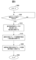
- FIG. 5 is a flowchart showing a process flow executed by the control device of the dump truck.
- FIG. 1 is a block diagram showing an example of the internal configuration of the dump truck 1. As shown in Fig.
- the dump truck 1 includes a storage battery 2 as a power source, a bidirectional power conversion device 3 connected to the storage battery 2, a motor 4, a DC reactor 5, a voltage detector 6, a DC bus capacitor 7, a power converter 8, a gear 9, wheels 10, a regenerative brake circuit 11, a control device 12, a voltage command switching command unit 13, and a DC bus current sensor 14.
- the dump truck 1 is an electric dump truck, an electric vehicle that runs on an electric motor 4 driven by electricity supplied from a storage battery 2 as a power source.
- the storage battery 2 is a battery module that includes a battery pack made up of multiple secondary batteries that can be charged and discharged.
- the bidirectional power conversion device 3 is connected to the storage battery 2.
- the bidirectional power conversion device 3 is connected to the power converter 8 via a power line.
- the bidirectional power conversion device 3 is controlled by the control device 12.
- the bidirectional power conversion device 3 is, for example, a bidirectional DC-DC converter (bidirectional chopper), and when the dump truck 1 is operated using power from the storage battery 2, it converts the DC power input from the storage battery 2 to a voltage in accordance with a voltage command and outputs it.
- the bidirectional power conversion device 3 converts the DC power input from the power converter 8 to a voltage in accordance with a voltage command and outputs it to the storage battery 2.
- the DC reactor 5 smoothes the current.
- the voltage detector 6 is connected to both terminals of the bidirectional power conversion device 3. When the voltage detector 6 detects a DC voltage (DC bus voltage), the detected DC voltage value is transmitted to the control device 12.
- the DC bus capacitor 7 is connected in parallel to the bidirectional power converter 3.
- the DC bus capacitor 7 charges and smoothes the DC voltage supplied from the bidirectional power converter 3.
- the power converter 8 is connected in parallel to the DC bus capacitor 7 and converts the smoothed DC power output from the DC bus capacitor 7 into AC power.
- the electric motor 4 is driven by AC power output from the power converter 8, and drives the gear 9.
- the wheels 10 are driven by the electric motor 4 via the gear 9. This allows the dump truck 1 to travel.
- the electric motor 4 also operates as a generator during regenerative braking.
- the DC bus current sensor 14 is connected between one terminal of the bidirectional power converter 3 and the connection point P1.
- the DC bus current sensor 14 outputs to the control device 12 the DC current value input to the bidirectional power converter 3 that is detected between the bidirectional power converter 3 and the connection point P1.
- the regenerative braking circuit 11 includes a step-down chopper 15 and a brake resistor 16.
- the regenerative braking circuit 11 converts electric power into thermal energy using the brake resistor 16 and consumes it.
- the step-down chopper 15 is capable of controlling the power consumption or current (voltage applied to the brake resistor 16) of the brake resistor 16.
- the step-down chopper 15 operates according to instructions from the control device 12, and performs a power consumption operation in which a current flows through the brake resistor 16 to consume electric power.
- the power consumption operation of the regenerative braking circuit 11 may also be referred to as a "power processing operation.”
- the control device 12 receives the DC current value from the DC bus current sensor 14 and the DC voltage value from the voltage detector 6.
- the control device 12 controls the bidirectional power conversion device 3 and the regenerative brake circuit 11.
- the control device 12 is, for example, an ECU (Electronic Control Unit).
- the ECU is a control unit (Electronic Control Unit) that includes a microcomputer as its main component, and is also called a controller.
- the microcomputer includes a CPU, ROM, RAM, and an interface (I/F), etc.
- the CPU realizes various functions by executing instructions (programs, routines) stored in the ROM.
- the control device 12 can also be configured in part or in whole from hardware. For example, the control device 12 may realize at least some of the various functions of the control device 12 using an FPGA (Field Programmable Gate Array) or the like.
- FPGA Field Programmable Gate Array
- the voltage command switching command unit 13 commands the control device 12 to switch the operation of the bidirectional power conversion device 3.
- the voltage command switching command unit 13 is composed of, for example, an ECU.
- the dump truck 1 discharges the storage battery 2 through the bidirectional power converter 3, and drives the electric motor 4 with the power of the storage battery 2 supplied through the power converter 8 to travel.
- the dump truck 1 outputs DC power from the storage battery 2 through the bidirectional power converter 3.
- the DC power output by the bidirectional power converter 3 is smoothed by a DC bus capacitor 7 and converted into AC power by the power converter 8.
- This AC power is output to the electric motor 4.
- the electric motor 4 connected to the power converter 8 is connected to wheels 10 through a gear 9. When the electric motor 4 drives the gear 9, the wheels 10 rotate, and the dump truck 1 moves forward or backward or accelerates.
- the dump truck 1 performs braking by regenerative braking that generates a desired braking force by using the electric motor 4 as a generator to convert kinetic energy into electrical energy in response to a command from an ECU (not shown) for controlling the electric motor.
- the dump truck 1 performs regenerative braking in response to a command from the ECU based on the driver's operation of an operating device for an auxiliary brake (retard brake) (not shown), for example.
- the power generated by the electric motor 4 (power generated) by regenerative braking is referred to as "regenerative power.”
- the regenerative power is input to the power converter 8, where it is converted from AC power to DC power and output.
- the regenerative power is used as power supplied to the storage battery 2 and is consumed in the regenerative brake circuit 11 as necessary.
- the dump truck 1 charges the storage battery 2 with the regenerative power by the bidirectional power conversion device 3.
- the dump truck 1 causes the regenerative brake circuit 11 to consume surplus regenerative power that exceeds the chargeable power among the regenerative power.
- the chargeable power of the storage battery 2 depends on the SOC (State of Charge), the chargeable power is also constantly changing.
- SOC State of Charge
- the regenerative power and the chargeable power are constantly changing, it is necessary to optimally allocate the regenerative power of the motor 4 to the charging power of the storage battery 2 and the power consumption of the regenerative brake circuit 11, and stably control the DC bus voltage.
- the operating voltage at which the bidirectional power conversion device 3 starts the charging operation (charging power control of the storage battery 2) is separated from the operating voltage at which the regenerative braking circuit 11 starts the power consumption operation.
- the operating voltage of the regenerative braking circuit 11 is set higher than the operating voltage of the bidirectional power conversion device 3.
- the operating voltage of the regenerative braking circuit 11 may also be referred to as the "first operating voltage.”
- the operating voltage of the charging operation of the bidirectional power conversion device 3 may also be referred to as the "second operating voltage.”
- the operating voltage of the charging operation of the bidirectional power conversion device 3 may also be referred to as the "charging power control operating voltage.”
- the charging power control of the bidirectional power conversion device 3 can stably control the DC bus voltage without fluctuating.
- the dump truck 1 according to the embodiment can stably control the DC bus voltage even if the regenerative power suddenly drops when the regenerative braking circuit 11 is operating and consuming surplus power.
- the dump truck 1 according to the first embodiment can increase the power consumption of the regenerative braking circuit 11 and stably control the DC bus voltage when the chargeable power suddenly drops. As described above, the dump truck 1 according to the first embodiment can stably control the DC bus voltage.
- Figure 2A is a graph showing an example of changes in regenerative power, charging power, power consumption of the regenerative brake circuit 11, and DC bus voltage when the operating voltage of the regenerative brake circuit 11 and the operating voltage of the charging power control are set to the same.
- the regenerative power increases during the period from time t1 to the time immediately prior to time t2.
- the chargeable power which is the maximum power that can be input to the storage battery 2
- the regenerative brake circuit 11 is activated.
- the dump truck 1 distributes the chargeable portion of the regenerative power to the storage battery 2, charges the storage battery 2, and consumes the portion of the regenerative power that exceeds the chargeable portion in the regenerative brake circuit 11.
- Figure 2B is a graph showing another example of the changes in regenerative power, charging power, power consumption of the regenerative brake circuit 11, and DC bus voltage when the operating voltage of the regenerative brake circuit 11 and the operating voltage of the charging power control are set to the same.
- the regenerative power increases during the period from time t1 to the time immediately prior to time t2.
- the chargeable power which is the maximum power that can be input to the storage battery 2
- the regenerative brake circuit 11 is activated.
- the dump truck 1 distributes the chargeable portion of the regenerative power to the storage battery 2, charges the storage battery 2, and consumes the portion of the regenerative power that exceeds the chargeable portion in the regenerative brake circuit 11.
- Figure 3A is a graph showing an example of the changes in regenerative power, charging power, power consumption of the regenerative brake circuit 11, and DC bus voltage when the operating voltage of the regenerative brake circuit 11 is made higher than the operating voltage of the charging power control.
- the regenerative brake circuit 11 When the regenerative power exceeds the chargeable power (the chargeable power, which is the maximum power that can be input to the storage battery 2) at time t2, the DC bus voltage rises, and when it reaches the operating voltage of the regenerative brake circuit 11, the regenerative brake circuit 11 is activated. The regenerative brake circuit 11 starts consuming power, and the power consumption in the regenerative brake circuit 11 rises and becomes stable. When the regenerative brake circuit 11 starts consuming power, the dump truck 1 distributes the chargeable power portion of the regenerative power to the storage battery 2, charges the storage battery 2, and consumes the regenerative power that exceeds the chargeable power in the regenerative brake circuit 11.
- the chargeable power which is the maximum power that can be input to the storage battery 2
- the regenerative brake circuit 11 When the regenerative brake circuit 11 starts consuming power, the dump truck 1 distributes the chargeable power portion of the regenerative power to the storage battery 2, charges the storage battery 2, and consumes the regenerative power that exceeds the chargeable
- the dump truck 1 when the regenerative power suddenly decreases, the dump truck 1 according to the embodiment can stably control the DC bus voltage by suppressing the power consumption in the regenerative brake circuit 11.
- Figure 3B is a graph showing another example of the changes in regenerative power, charging power, power consumption of the regenerative brake circuit 11, and DC bus voltage when the operating voltage of the regenerative brake circuit 11 is made higher than the operating voltage of the charging power control.
- the regenerative brake circuit 11 When the regenerative power exceeds the chargeable power (the chargeable power, which is the maximum power that can be input to the storage battery 2) at time t2, the DC bus voltage rises, and when it reaches the operating voltage of the regenerative brake circuit 11, the regenerative brake circuit 11 is activated. The regenerative brake circuit 11 starts consuming power, and the power consumption in the regenerative brake circuit 11 rises and becomes stable. When the regenerative brake circuit 11 starts consuming power, the dump truck 1 distributes the chargeable power portion of the regenerative power to the storage battery 2, charges the storage battery 2, and consumes the regenerative power that exceeds the chargeable power in the regenerative brake circuit 11.
- the chargeable power which is the maximum power that can be input to the storage battery 2
- the regenerative brake circuit 11 When the regenerative brake circuit 11 starts consuming power, the dump truck 1 distributes the chargeable power portion of the regenerative power to the storage battery 2, charges the storage battery 2, and consumes the regenerative power that exceeds the chargeable
- the dump truck 1 according to the embodiment even if the chargeable power is suddenly decreased, the power consumption of the regenerative brake circuit 11 is increased by that amount, and the DC bus voltage is controlled to be constant.
- the dump truck 1 according to the first embodiment of the present invention appropriately distributes regenerative power into power for charging and power for the regenerative brake circuit 11, thereby enabling stable control of the DC bus voltage.
- the dump truck 1 according to the second embodiment of the present invention will be described.
- the dump truck 1 according to the second embodiment differs from the dump truck 1 according to the first embodiment only in the following points.
- the potential difference with the bidirectional power conversion device 3 is calculated by detecting/estimating the DC current, and the operating voltage of the regenerative brake circuit 11 is corrected in accordance with the potential difference. This makes it possible to stably control the DC bus voltage.
- the potential difference between the bidirectional power conversion device 3 is calculated by detecting/estimating the DC current, and the operating voltage of the regenerative brake circuit 11 is corrected according to the potential difference, thereby achieving more stable control of the DC bus voltage.
- Figure 4 is a graph showing an example of the changes in regenerative power, charging power, power consumption of the regenerative brake circuit 11, and DC bus voltage when the operating voltage of the regenerative brake circuit 11 is made higher than the charging power control operating voltage, and the potential difference with the bidirectional power conversion device 3 is calculated by detecting/estimating the DC current, and the operating voltage of the regenerative brake circuit 11 is corrected according to the potential difference.
- the DC bus voltage reaches the charging power control operating voltage, so the bidirectional power conversion device 3 starts charging the storage battery 2, and as the regenerative power increases, the charging power of the storage battery 2 also increases. Also, during this period, the potential difference with the bidirectional power conversion device 3 is calculated by detecting/estimating the DC current, and the operating voltage of the regenerative brake circuit 11 is corrected (added) according to the potential difference. Therefore, the operating voltage of the regenerative brake circuit 11 starts to rise from time t1.
- the regenerative brake circuit 11 When the regenerative power exceeds the chargeable power (the chargeable power, which is the maximum power that can be input to the storage battery 2) at time t2, the DC bus voltage rises, and when it reaches the operating voltage of the regenerative brake circuit 11, the regenerative brake circuit 11 is activated. The regenerative brake circuit 11 starts consuming power, and the power consumption in the regenerative brake circuit 11 rises and becomes stable. When the regenerative brake circuit 11 starts consuming power, the dump truck 1 distributes the chargeable power portion of the regenerative power to the storage battery 2, charges the storage battery 2, and consumes the regenerative power that exceeds the chargeable power in the regenerative brake circuit 11.
- the chargeable power which is the maximum power that can be input to the storage battery 2
- the regenerative brake circuit 11 When the regenerative brake circuit 11 starts consuming power, the dump truck 1 distributes the chargeable power portion of the regenerative power to the storage battery 2, charges the storage battery 2, and consumes the regenerative power that exceeds the chargeable
- FIG 5 is a flowchart showing a process flow executed by the control device 12 of the dump truck 1.
- the control device 12 starts processing from step 500 in FIG. 5 and proceeds to step 505, where it determines whether the storage battery 2 is being charged.
- control device 12 judges "NO” in step 505 and executes the process of step 705 again. If the storage battery 2 is being charged, the control device 12 judges "YES” in step 505 and executes the processes of steps 510 to 520 described below in order.
- Step 510 The control device 12 calculates (estimates) the potential difference between the bidirectional power conversion device 3 and the regenerative brake circuit 11 according to the detection value of the DC bus current sensor. For example, the control device 12 calculates the potential difference by referring to a map that defines the relationship between the current and the potential difference. The potential difference is calculated (estimated) so that the larger the current, the larger the potential difference.
- Step 515 The control device 12 adds the potential difference to a predetermined reference operating voltage of the regenerative brake circuit 11.
- the predetermined reference operating voltage is set to be greater than the charging power control operating voltage, for example.
- Step 520 The control device 12 sets the voltage obtained by adding the potential difference to a predetermined reference operating voltage as the operating voltage of the regenerative brake circuit 11.
- control device 12 proceeds to step 595 and ends this processing flow.
- control device 12 may execute the following step A instead of steps 515 and 520.
- Step A The controller 12 increases or decreases the operating voltage based on the potential difference.
- the dump truck 1 according to the second embodiment of the present invention appropriately distributes regenerative power into power for charging and power for the regenerative braking circuit 11, taking into account the potential difference, so that the DC voltage of the DC bus can be stably controlled between the operating voltage of the regenerative braking circuit 11 and the operating voltage of the charging power control.
- ⁇ Modifications>> The present invention is not limited to the above-described embodiments, and various modified examples can be adopted within the scope of the present invention. Furthermore, the above-described embodiments can be combined with each other without departing from the scope of the present invention.
- the regenerative braking circuit 11 may be a power storage circuit including a storage battery 2 for driving a device other than the electric motor 4. In this case, instead of consuming power, the regenerative braking circuit 11 stores a portion of the regenerative power by charging the storage battery 2. For convenience, the operation of the regenerative braking circuit 11 to store power may also be referred to as a "power processing operation.”
Landscapes
- Engineering & Computer Science (AREA)
- Power Engineering (AREA)
- Transportation (AREA)
- Mechanical Engineering (AREA)
- Electric Propulsion And Braking For Vehicles (AREA)
Priority Applications (4)
| Application Number | Priority Date | Filing Date | Title |
|---|---|---|---|
| EP23936644.6A EP4711183A1 (en) | 2023-05-11 | 2023-05-11 | Electric vehicle |
| PCT/JP2023/017801 WO2024232096A1 (ja) | 2023-05-11 | 2023-05-11 | 電動車両 |
| AU2023447265A AU2023447265A1 (en) | 2023-05-11 | 2023-05-11 | Electric vehicle |
| JP2025519295A JPWO2024232096A1 (https=) | 2023-05-11 | 2023-05-11 |
Applications Claiming Priority (1)
| Application Number | Priority Date | Filing Date | Title |
|---|---|---|---|
| PCT/JP2023/017801 WO2024232096A1 (ja) | 2023-05-11 | 2023-05-11 | 電動車両 |
Publications (1)
| Publication Number | Publication Date |
|---|---|
| WO2024232096A1 true WO2024232096A1 (ja) | 2024-11-14 |
Family
ID=93429926
Family Applications (1)
| Application Number | Title | Priority Date | Filing Date |
|---|---|---|---|
| PCT/JP2023/017801 Ceased WO2024232096A1 (ja) | 2023-05-11 | 2023-05-11 | 電動車両 |
Country Status (4)
| Country | Link |
|---|---|
| EP (1) | EP4711183A1 (https=) |
| JP (1) | JPWO2024232096A1 (https=) |
| AU (1) | AU2023447265A1 (https=) |
| WO (1) | WO2024232096A1 (https=) |
Citations (5)
| Publication number | Priority date | Publication date | Assignee | Title |
|---|---|---|---|---|
| JP2007097343A (ja) * | 2005-09-29 | 2007-04-12 | Toyota Motor Corp | 電力制御装置および電動車両 |
| JP2016096655A (ja) * | 2014-11-14 | 2016-05-26 | 西日本旅客鉄道株式会社 | 駆動システム、及び気動車 |
| WO2016088247A1 (ja) * | 2014-12-05 | 2016-06-09 | 株式会社安川電機 | ブレーキ制御システム、車両、モータ、ブレーキ制御方法 |
| JP2017158389A (ja) * | 2016-03-04 | 2017-09-07 | 本田技研工業株式会社 | 車両 |
| JP2020124001A (ja) | 2019-01-29 | 2020-08-13 | 株式会社日立インダストリアルプロダクツ | 回生ブレーキシステム及び電気駆動車両 |
-
2023
- 2023-05-11 EP EP23936644.6A patent/EP4711183A1/en active Pending
- 2023-05-11 WO PCT/JP2023/017801 patent/WO2024232096A1/ja not_active Ceased
- 2023-05-11 AU AU2023447265A patent/AU2023447265A1/en active Pending
- 2023-05-11 JP JP2025519295A patent/JPWO2024232096A1/ja active Pending
Patent Citations (5)
| Publication number | Priority date | Publication date | Assignee | Title |
|---|---|---|---|---|
| JP2007097343A (ja) * | 2005-09-29 | 2007-04-12 | Toyota Motor Corp | 電力制御装置および電動車両 |
| JP2016096655A (ja) * | 2014-11-14 | 2016-05-26 | 西日本旅客鉄道株式会社 | 駆動システム、及び気動車 |
| WO2016088247A1 (ja) * | 2014-12-05 | 2016-06-09 | 株式会社安川電機 | ブレーキ制御システム、車両、モータ、ブレーキ制御方法 |
| JP2017158389A (ja) * | 2016-03-04 | 2017-09-07 | 本田技研工業株式会社 | 車両 |
| JP2020124001A (ja) | 2019-01-29 | 2020-08-13 | 株式会社日立インダストリアルプロダクツ | 回生ブレーキシステム及び電気駆動車両 |
Non-Patent Citations (1)
| Title |
|---|
| See also references of EP4711183A1 |
Also Published As
| Publication number | Publication date |
|---|---|
| AU2023447265A1 (en) | 2025-09-11 |
| JPWO2024232096A1 (https=) | 2024-11-14 |
| EP4711183A1 (en) | 2026-03-18 |
Similar Documents
| Publication | Publication Date | Title |
|---|---|---|
| JP6270009B2 (ja) | 車両の電力制御装置 | |
| US7221064B2 (en) | Power circuit for battery | |
| JP6493992B2 (ja) | 電動車両の制御装置及び電動車両 | |
| US11485234B2 (en) | Power supply system | |
| US11203274B2 (en) | Electrically driven vehicle | |
| CN109639137B (zh) | 电源装置 | |
| JP5987846B2 (ja) | ハイブリッド車両 | |
| US11070156B2 (en) | Power system | |
| US11427179B2 (en) | Power supply system | |
| US12083899B2 (en) | Power supply system | |
| CN108454419B (zh) | 电池系统的控制装置和电池系统 | |
| US9834100B2 (en) | Charge/discharge system | |
| US10239530B2 (en) | Vehicle control apparatus for a regenerative braking system based on the battery input power | |
| CN109130882B (zh) | 货运汽车及搭载于货运汽车的行驶用驱动马达的控制方法 | |
| CN106458055A (zh) | 用于车辆的驱动控制系统 | |
| US20250145030A1 (en) | Vehicle | |
| KR101836643B1 (ko) | 차량용 마일드 하이브리드 시스템 | |
| JP4656061B2 (ja) | ハイブリッド車両の定速走行制御装置 | |
| WO2024232096A1 (ja) | 電動車両 | |
| JP2017103003A (ja) | 燃料電池システム | |
| JP6270010B2 (ja) | 車両の電力制御装置 | |
| JP2024068371A (ja) | バッテリ制御装置 | |
| JP5814156B2 (ja) | 電動車両およびその制御方法 | |
| WO2017159042A1 (ja) | 電力制御装置および車両 | |
| JP2006074852A (ja) | Soc推定装置及びこれを搭載した電動車両 |
Legal Events
| Date | Code | Title | Description |
|---|---|---|---|
| 121 | Ep: the epo has been informed by wipo that ep was designated in this application |
Ref document number: 23936644 Country of ref document: EP Kind code of ref document: A1 |
|
| WWE | Wipo information: entry into national phase |
Ref document number: 2025519295 Country of ref document: JP |
|
| WWE | Wipo information: entry into national phase |
Ref document number: AU2023447265 Country of ref document: AU |
|
| ENP | Entry into the national phase |
Ref document number: 2023447265 Country of ref document: AU Date of ref document: 20230511 Kind code of ref document: A |
|
| WWE | Wipo information: entry into national phase |
Ref document number: 2023936644 Country of ref document: EP |
|
| NENP | Non-entry into the national phase |
Ref country code: DE |
|
| ENP | Entry into the national phase |
Ref document number: 2023936644 Country of ref document: EP Effective date: 20251211 |
|
| ENP | Entry into the national phase |
Ref document number: 2023936644 Country of ref document: EP Effective date: 20251211 |
|
| ENP | Entry into the national phase |
Ref document number: 2023936644 Country of ref document: EP Effective date: 20251211 |
|
| ENP | Entry into the national phase |
Ref document number: 2023936644 Country of ref document: EP Effective date: 20251211 |
|
| ENP | Entry into the national phase |
Ref document number: 2023936644 Country of ref document: EP Effective date: 20251211 |
|
| ENP | Entry into the national phase |
Ref document number: 2023936644 Country of ref document: EP Effective date: 20251211 |
|
| ENP | Entry into the national phase |
Ref document number: 2023936644 Country of ref document: EP Effective date: 20251211 |
|
| ENP | Entry into the national phase |
Ref document number: 2023936644 Country of ref document: EP Effective date: 20251211 |
|
| ENP | Entry into the national phase |
Ref document number: 2023936644 Country of ref document: EP Effective date: 20251211 |