WO2024228360A1 - 繊維物品 - Google Patents
繊維物品 Download PDFInfo
- Publication number
- WO2024228360A1 WO2024228360A1 PCT/JP2024/016295 JP2024016295W WO2024228360A1 WO 2024228360 A1 WO2024228360 A1 WO 2024228360A1 JP 2024016295 W JP2024016295 W JP 2024016295W WO 2024228360 A1 WO2024228360 A1 WO 2024228360A1
- Authority
- WO
- WIPO (PCT)
- Prior art keywords
- fiber
- fibers
- range
- fiber article
- article
- Prior art date
- Legal status (The legal status is an assumption and is not a legal conclusion. Google has not performed a legal analysis and makes no representation as to the accuracy of the status listed.)
- Ceased
Links
Images

Classifications
-
- D—TEXTILES; PAPER
- D04—BRAIDING; LACE-MAKING; KNITTING; TRIMMINGS; NON-WOVEN FABRICS
- D04H—MAKING TEXTILE FABRICS, e.g. FROM FIBRES OR FILAMENTARY MATERIAL; FABRICS MADE BY SUCH PROCESSES OR APPARATUS, e.g. FELTS, NON-WOVEN FABRICS; COTTON-WOOL; WADDING ; NON-WOVEN FABRICS FROM STAPLE FIBRES, FILAMENTS OR YARNS, BONDED WITH AT LEAST ONE WEB-LIKE MATERIAL DURING THEIR CONSOLIDATION
- D04H1/00—Non-woven fabrics formed wholly or mainly of staple fibres or like relatively short fibres
- D04H1/40—Non-woven fabrics formed wholly or mainly of staple fibres or like relatively short fibres from fleeces or layers composed of fibres without existing or potential cohesive properties
- D04H1/42—Non-woven fabrics formed wholly or mainly of staple fibres or like relatively short fibres from fleeces or layers composed of fibres without existing or potential cohesive properties characterised by the use of certain kinds of fibres insofar as this use has no preponderant influence on the consolidation of the fleece
- D04H1/4382—Stretched reticular film fibres; Composite fibres; Mixed fibres; Ultrafine fibres; Fibres for artificial leather
- D04H1/43835—Mixed fibres, e.g. at least two chemically different fibres or fibre blends
-
- D—TEXTILES; PAPER
- D04—BRAIDING; LACE-MAKING; KNITTING; TRIMMINGS; NON-WOVEN FABRICS
- D04H—MAKING TEXTILE FABRICS, e.g. FROM FIBRES OR FILAMENTARY MATERIAL; FABRICS MADE BY SUCH PROCESSES OR APPARATUS, e.g. FELTS, NON-WOVEN FABRICS; COTTON-WOOL; WADDING ; NON-WOVEN FABRICS FROM STAPLE FIBRES, FILAMENTS OR YARNS, BONDED WITH AT LEAST ONE WEB-LIKE MATERIAL DURING THEIR CONSOLIDATION
- D04H1/00—Non-woven fabrics formed wholly or mainly of staple fibres or like relatively short fibres
- D04H1/40—Non-woven fabrics formed wholly or mainly of staple fibres or like relatively short fibres from fleeces or layers composed of fibres without existing or potential cohesive properties
- D04H1/413—Non-woven fabrics formed wholly or mainly of staple fibres or like relatively short fibres from fleeces or layers composed of fibres without existing or potential cohesive properties containing granules other than absorbent substances
-
- D—TEXTILES; PAPER
- D04—BRAIDING; LACE-MAKING; KNITTING; TRIMMINGS; NON-WOVEN FABRICS
- D04H—MAKING TEXTILE FABRICS, e.g. FROM FIBRES OR FILAMENTARY MATERIAL; FABRICS MADE BY SUCH PROCESSES OR APPARATUS, e.g. FELTS, NON-WOVEN FABRICS; COTTON-WOOL; WADDING ; NON-WOVEN FABRICS FROM STAPLE FIBRES, FILAMENTS OR YARNS, BONDED WITH AT LEAST ONE WEB-LIKE MATERIAL DURING THEIR CONSOLIDATION
- D04H1/00—Non-woven fabrics formed wholly or mainly of staple fibres or like relatively short fibres
- D04H1/40—Non-woven fabrics formed wholly or mainly of staple fibres or like relatively short fibres from fleeces or layers composed of fibres without existing or potential cohesive properties
- D04H1/42—Non-woven fabrics formed wholly or mainly of staple fibres or like relatively short fibres from fleeces or layers composed of fibres without existing or potential cohesive properties characterised by the use of certain kinds of fibres insofar as this use has no preponderant influence on the consolidation of the fleece
- D04H1/4382—Stretched reticular film fibres; Composite fibres; Mixed fibres; Ultrafine fibres; Fibres for artificial leather
-
- D—TEXTILES; PAPER
- D04—BRAIDING; LACE-MAKING; KNITTING; TRIMMINGS; NON-WOVEN FABRICS
- D04H—MAKING TEXTILE FABRICS, e.g. FROM FIBRES OR FILAMENTARY MATERIAL; FABRICS MADE BY SUCH PROCESSES OR APPARATUS, e.g. FELTS, NON-WOVEN FABRICS; COTTON-WOOL; WADDING ; NON-WOVEN FABRICS FROM STAPLE FIBRES, FILAMENTS OR YARNS, BONDED WITH AT LEAST ONE WEB-LIKE MATERIAL DURING THEIR CONSOLIDATION
- D04H1/00—Non-woven fabrics formed wholly or mainly of staple fibres or like relatively short fibres
- D04H1/40—Non-woven fabrics formed wholly or mainly of staple fibres or like relatively short fibres from fleeces or layers composed of fibres without existing or potential cohesive properties
- D04H1/42—Non-woven fabrics formed wholly or mainly of staple fibres or like relatively short fibres from fleeces or layers composed of fibres without existing or potential cohesive properties characterised by the use of certain kinds of fibres insofar as this use has no preponderant influence on the consolidation of the fleece
- D04H1/4391—Non-woven fabrics formed wholly or mainly of staple fibres or like relatively short fibres from fleeces or layers composed of fibres without existing or potential cohesive properties characterised by the use of certain kinds of fibres insofar as this use has no preponderant influence on the consolidation of the fleece characterised by the shape of the fibres
- D04H1/43918—Non-woven fabrics formed wholly or mainly of staple fibres or like relatively short fibres from fleeces or layers composed of fibres without existing or potential cohesive properties characterised by the use of certain kinds of fibres insofar as this use has no preponderant influence on the consolidation of the fleece characterised by the shape of the fibres nonlinear fibres, e.g. crimped or coiled fibres
Definitions
- the present disclosure relates to a fiber article including a first fiber and a second fiber having an outer diameter smaller than that of the first fiber.
- a fiber article used in applications such as air conditioner filters for example, as disclosed in Patent Document 1, a fiber article including a first fiber and a second fiber having a smaller outer diameter than the first fiber is known.
- the second fiber is supported by the first fiber, and the functions of the first fiber and the second fiber are expressed, thereby improving the performance of the fiber article.
- the fiber article could be made lighter and have improved strength, for example.
- the present disclosure therefore aims to provide a fiber article that includes a first fiber and a second fiber that has a smaller outer diameter than the first fiber, and that is lightweight and has improved strength.
- a fiber article is a sheet-like fiber article comprising a plurality of first fibers and a plurality of second fibers having an outer diameter smaller than the first fibers and supported by the first fibers in a dispersed state, the fiber article having a basis weight of 60 g/ m2 or more and 300 g/m2 or less , and a tensile strength in a minimum strength direction, in which the tensile strength is at a minimum among directions perpendicular to the thickness direction, of 0.8 N/10 mm or more and 100 N/10 mm or less.
- a fiber article including a first fiber and a second fiber having an outer diameter smaller than that of the first fiber, it is possible to reduce the weight of the fiber article and improve its strength.
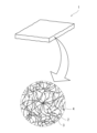
- FIG. 1 is a schematic diagram of a fiber article according to a first embodiment.
- FIG. 5 is a cross-sectional view of a fiber composite according to a second embodiment.
- the inventors of the present application have thoroughly investigated the above problem and have found that when manufacturing a textile article, by focusing on the basis weight of the textile article to be manufactured and the tensile strength in the minimum strength direction in which the tensile strength is at its minimum, and adjusting these values so that they fall within a predetermined range, the textile article can be made lighter and its strength improved.
- the present disclosure solves the above problem by configuring a textile article to have excellent tensile strength despite having a relatively low basis weight.
- FIG. 1 is a schematic diagram of a fiber article 1 according to a first embodiment.
- FIG. 1 also illustrates an enlarged view that shows a schematic internal structure of the fiber article 1.
- the fiber article 1 shown in FIG. 1 is, for example, a filter member that is disposed in a flow path through which a predetermined fluid flows and filters out impurities mixed in the fluid.
- the fluid passing through the inside of the fiber article 1 may be either a gas or a liquid.
- the gas is, for example, air.
- the fiber article 1 is in a sheet shape.
- the fiber article 1 includes a plurality of first fibers 2 and a plurality of second fibers 3 that have an outer diameter smaller than the first fibers 2 and are supported by the first fibers 2 in a dispersed state.
- the basis weight of the fiber article 1 is set to a value in the range of 60 g/ m2 to 300 g/ m2 (152 g/ m2 as one example).
- the basis weight is preferably a value in the range of 60 g/ m2 to 250 g/ m2 , and more preferably a value in the range of 60 g/ m2 to 200 g/ m2 .
- the basis weight is preferably a value in the range of 80 g/ m2 to 200 g/ m2 , and more preferably a value in the range of 100 g/ m2 to 200 g/ m2 .
- the tensile strength of the fiber article 1 in the minimum strength direction (hereinafter also referred to as the "first direction"), which is the direction perpendicular to the thickness direction and in which the tensile strength is the smallest, is at least 0.8 N/10 mm or more.
- the unit “N/10 mm” indicates how many N of load can be withstood per 10 mm of measured width.
- the "minimum strength direction” here refers to the width direction of the fiber sheet (hereinafter also simply referred to as the "fiber sheet”), which is the intermediate product of the fiber article 1 before it is cut, in a production line that continuously produces the fiber article 1.
- the "minimum strength direction” corresponds to the width direction perpendicular to the conveying direction of the fiber sheet.
- the first fibers contained in the fiber sheet are continuously spun by a melt spinning method, an electrospinning method, a dry spinning method, or the like, the first fibers of the long fibers discharged from the spinning tube are oriented to extend in the conveying direction.
- a normal fiber product has a configuration in which multiple fibers extend in a direction perpendicular to the thickness direction, which is perpendicular to the direction of minimum strength (in other words, a direction corresponding to the conveying direction of the fiber sheet in the manufacturing line; hereinafter, also referred to as the "second direction").
- the direction of minimum strength in other words, a direction corresponding to the conveying direction of the fiber sheet in the manufacturing line; hereinafter, also referred to as the "second direction".
- the strength of the fiber product is the smallest among the multiple directions perpendicular to the thickness direction.
- the tensile strength of the fiber article 1 of this embodiment in the minimum strength direction is set to a value in the range of at least 0.8 N/10 mm or more, thereby improving the tensile strength in that direction.
- the abundant second fibers 3 are formed to extend in the width direction of the fiber sheet during manufacturing. This increases the entanglement of the first fibers 2 and second fibers 3 in the minimum strength direction of the fiber article 1. As a result, the tensile strength of the fiber article 1 in the minimum strength direction is improved by the abundant first fibers 2 and second fibers 3.
- the tensile strength of the fiber article 1 in the direction of minimum strength is a value in the range of 100 N/10 mm or less. This, for example, prevents the tensile strength of the fiber article 1 from increasing excessively, making it easier to manufacture the fiber article 1.
- the tensile strength of the fiber article 1 in this embodiment in the direction of minimum strength is a value in the range of 0.8 N/10 mm or more and 100 N/10 mm or less.
- the range of the tensile strength in the direction of minimum strength is preferably, for example, a value in the range of 1 N/10 mm or more and 100 N/10 mm or less, and more preferably, a value in the range of 5 N/10 mm or more and 100 N/10 mm or less.
- the range of the tensile strength in the direction of minimum strength is preferably, for example, a value in the range of 8 N/10 mm or more and 100 N/10 mm or less, and more preferably, a value in the range of 10 N/10 mm or more and 100 N/10 mm or less.
- the tensile elongation of the fiber article 1 of this embodiment with respect to the natural state in the direction of minimum strength is at least a value in the range of 5% or more. Furthermore, the tensile elongation of the fiber article 1 of this embodiment is a value in the range of 250% or less. That is, the tensile elongation of the fiber article 1 of this embodiment is a value in the range of 5% or more and 250% or less. This makes the fiber article 1 less likely to break even if an external force acts in the direction of minimum strength.
- the tensile elongation is preferably, for example, a value in the range of 10% or more and 250% or less, and more preferably a value in the range of 20% or more and 250% or less. In another example, the tensile elongation is preferably, for example, a value in the range of 30% or more and 250% or less, and more preferably a value in the range of 40% or more and 250% or less.
- the fiber article 1 of this embodiment is set to a thickness value in the range of less than 3.0 mm (1.1 mm as an example).
- the thickness of the fiber article 1 is, for example, a value in the range of 0.1 mm or more and less than 3.0 mm.
- this thickness is preferably a value in the range of 0.1 mm or more and 2.5 mm or less, and more preferably a value in the range of 0.1 mm or more and 2.0 mm or less.
- this thickness is preferably a value in the range of 0.5 mm or more and 2.5 mm or less, and more preferably a value in the range of 1.0 mm or more and 2.5 mm or less.
- the "thickness" of the fiber article 1 in this specification refers to the thickness of the fiber article 1 in its natural state.
- the PF value of the fiber article 1 of this embodiment is set to a value in the range of 16 to 84 (for example, 64).
- the PF value referred to here refers to a value calculated based on the following formulas 2, 3, and 4.
- NaCl particles having a particle diameter of 0.4 ⁇ m are used, which are generated in accordance with the method described in JIS B9928 Appendix 5 (regulations) NaCl aerosol generation method (pressure spray method). Air containing these NaCl particles is passed through the fiber article 1 in the thickness direction at a flow rate of 5.3 cm/sec, and the number of NaCl particles before and after passing through the fiber article 1 is measured by a particle counter.
- the transmittance (%) is calculated based on this measurement value.
- Transmittance (%) (CO/CI) x 100 where CO is the number of NaCl particles after passing through the fiber article 1, and CI is the number of NaCl particles before passing through the fiber article 1.
- Collection efficiency (%) 100 - transmittance (%)
- PF value ⁇ -log((100-collection efficiency (%))/100 ⁇ /(pressure loss (Pa)/1000)
- the PF value is preferably, for example, in the range of 16 to 70, and more preferably, in the range of 16 to 60. In another example, the PF value is preferably, for example, in the range of 20 to 84, and more preferably, in the range of 25 to 84.
- the pressure loss of the fiber article 1 of this embodiment when air is passed through it in the thickness direction at a flow rate of 5.3 cm/sec is set to a value in the range of 3 Pa to 35 Pa (6 Pa as an example).
- this pressure loss is preferably a value in the range of 3 Pa to 25 Pa, and more preferably a value in the range of 3 Pa to 15 Pa.
- This pressure loss is measured, for example, by the following procedure.
- the measurement sample is set in a holder with an inner diameter of 113 mm (effective area as a filter medium: 100 cm 2 ).
- the flow rate of the air flowing through the measurement sample is adjusted to 5.3 cm/sec using a flow meter.
- the pressure loss occurring between the upstream and downstream sides of the measurement sample in the air flow direction at this time is measured using a manometer.
- the collection efficiency calculated by formula 3 is set to a value in the range of 35% to 95% (as an example, 61%).
- this collection efficiency is preferably a value in the range of 35% to 85%, and more preferably a value in the range of 35% to 75%.
- a value in the range of 40% to 90% is preferred, and more preferably a value in the range of 45% to 90%.
- the fiber article 1 of this embodiment has a nonwoven structure.
- the first fibers 2 are, for example, short fibers.
- the first fibers 2 have a length in the range of 10 mm to 100 mm.
- the first fibers 2 have a higher strength (e.g., tensile strength) than the second fibers 3.
- the multiple first fibers 2 form the main skeleton of the fiber article 1.
- the first fibers 2 of this embodiment are crimped. By using multiple crimped first fibers 2, the fiber density of the fiber article 1 is reduced compared to when multiple uncrimped first fibers 2 are used. Also, as an example, the first fibers 2 are longer than the second fibers 3. As a result, even if the number of first fibers 2 is relatively small, the abundant second fibers 3 can be stably supported by the first fibers 2.
- the outer diameter D2 of the second fibers 3 is smaller than the outer diameter D1 of the first fibers 2. Therefore, the fiber article 1 has a composite structure of fibers with different diameters.
- the second fibers 3 are supported by the first fibers 2 in a state where they are dispersed in the fiber article 1. At least a portion of the second fibers 3 is attached to the first fibers 2.
- the ratio D1/D2 of the outer diameter D1 of the first fibers 2 to the outer diameter D2 of the second fibers 3 is set to a value in the range of 15.0 to 1666.7.
- the fiber article 1 of this embodiment includes, as an example, first fibers 2 with a large outer diameter D1 and second fibers 3 with an outer diameter D2 that is significantly smaller than the outer diameter D1.
- the ratio D1/D2 is preferably in the range of 15.0 to 1300.0, more preferably in the range of 15.0 to 714.3, and even more preferably in the range of 15.0 to 300.0.
- the ratio D1/D2 is preferably in the range of 60.0 to 1666.7, more preferably in the range of 60.0 to 1300.0, even more preferably in the range of 60.0 to 714.3, and even more preferably in the range of 60.0 to 300.0.
- the ratio D1/D2 is 15.0 or more, for example, in the fiber article 1, the functions of the first fiber 2 and the second fiber 3, which have different outer diameters, can be easily expressed. Furthermore, if the value of the ratio D1/D2 is 1666.7 or less, for example, the second fiber 3 can be easily laid around the first fiber 2 while suppressing an increase in the outer diameter D1 of the first fiber 2. Furthermore, by maintaining the outer diameter D2 at a certain value, the second fiber 3 can be easily formed. Furthermore, by setting the ratio D1/D2 to a value in the range of 60.0 to 1666.7, the filter performance of the fiber article 1 can be improved while the amount of the second fiber 3 used can be reduced, thereby suppressing the production cost of the fiber article 1.
- the outer diameter D1 is preferably, for example, in the range of 5.0 ⁇ m to 50.0 ⁇ m, and more preferably in the range of 20.0 ⁇ m to 30.0 ⁇ m.
- the outer diameter D2 is preferably, for example, in the range of 30.0 nm to 1.0 ⁇ m, more preferably in the range of 30.0 nm to 800 nm, and even more preferably in the range of 30.0 nm to 166.7 nm.
- the outer diameter D2 is preferably, for example, in the range of 50.0 nm to 800.0 nm.
- the ratio V1/V2 of the total volume V1 of the first fibers 2 to the total volume V2 of the second fibers 3 and the resin granules 4 is set to a value in the range of 1.9 to 124.0. It is further preferable that the ratio V1/V2 is set to a value in the range of 20.0 to 124.0.
- the textile article 1 has fiber gaps between the multiple crimped first fibers 2 and fiber gaps between the multiple second fibers 3.
- the textile article 1 has a mesh structure made up of the multiple crimped first fibers 2 and the multiple second fibers 3.
- the second fibers 3 are fixed to the first fibers 2, so that the mesh structure is not easily destroyed even when an external force is applied to the textile article 1.
- the second fibers 3 are supported by the first fibers 2 while being entangled with them. Therefore, even if the outer diameter D2 of the second fibers 3 is smaller than the outer diameter D1 of the first fibers 2, the second fibers 3 can be supported by the first fibers 2 while preventing damage to the second fibers 3 due to breakage, etc. Thus, the functionality of the second fibers 3 can be maintained for a long period of time.
- the second fibers 3 are also distributed over a wide area extending in the direction in which the first fibers 2 of the sheet-like fiber article 1 extend.
- the fiber article 1 has abundant fiber gaps formed by the first fibers 2 and the second fibers 3.
- the fiber article 1 is prevented from having uneven fiber gaps between the first fibers 2 and the second fibers 3 in the first and second directions that extend perpendicular to each other in a plane perpendicular to the thickness direction.
- the fluid can be brought into uniform contact with the first fibers 2 and the second fibers 3, making it easier to express the functions of the first fibers 2 and the second fibers 3.
- the mesh structure formed in the fiber article 1 allows the shape of the fiber article 1 to be maintained, and the filter performance of the fiber article 1 to be stably maintained.
- the second fibers 3 are formed, for example, from resin granules 4 attached to the first fibers 2 during the manufacture of the fiber article 1.
- the resin granules 4 are, for example, extrusion molded bodies manufactured by a paste extrusion molding method.
- the resin granules 4 contain polymers that can be fiberized.
- a first external force is applied to the resin granules 4 in a direction that compresses (reduces) the interfacial spaces between the first fibers 2, and then a second external force is applied in a direction that relaxes the first external force, thereby forming the second fibers 3 from the resin granules 4.
- the second fibers 3 can also be formed when the first external force applied to the resin granules 4 is relaxed, expanding the gaps between the multiple first fibers 2. However, in this embodiment, abundant second fibers 3 are actively formed by applying a second external force to the resin granules 4. As shown in the enlarged view in Figure 1, for example, some resin granules 4 remain in the fiber article 1 after production. Depending on the method of producing the fiber article 1, there are cases where no resin granules 4 remain in the fiber article 1.
- the resin granules 4 contain a lamellar structure.
- the term "lamellar structure” refers to a structure in which the polymer chains that make up the resin of the resin granules 4 are connected and folded.
- the lamellar structure contained in the resin granules 4 is composed of fine fibers formed by millions of these polymer chains being connected in a ribbon shape. These fine fibers are folded and stored inside the resin granules 4. By sequentially applying a first external force and a second external force to the resin granules 4, the fine fibers extend from inside the resin granules 4 towards the outside.
- a first external force is applied to a plurality of resin granules 4 attached to a plurality of first fibers 2, and then a second external force is applied in the conveying direction and the width direction to form a plurality of second fibers 3 extending in the conveying direction and a plurality of second fibers 3 extending in the width direction.
- the fiber gaps are appropriately enlarged, and a fiber article 1 having a basis weight in a range of 60 g/ m2 to 300 g/ m2 is produced.
- the material of the first fibers 2 can be selected as appropriate.
- an aqueous dispersion containing the resin granules 4 (hereinafter simply referred to as aqueous dispersion) is applied to the first fibers 2, thereby attaching the resin granules 4 to the first fibers 2.
- aqueous dispersion aqueous dispersion containing the resin granules 4
- the material of the first fibers 2 has a relatively low water contact angle ⁇ 1 immediately after water droplets are dropped on the surface of the first fibers 2.
- the first fibers 2 include at least one of rayon, polypropylene (PP), polyethylene terephthalate (PET), polyethylene (PE), and cellulose acetate. Such materials can suppress the water contact angle ⁇ 1 to a relatively low value.
- the first fibers 2 are cellulose acetate fibers.
- the textile article 1 includes a plurality of first fibers 2 obtained by crimping and opening a tow (tow band) containing cellulose acetate fibers. This makes it easy to obtain the desired bulkiness in the textile article 1.
- the first fibers 2 and the second fibers 3 have good affinity with each other.
- the second fibers 3 are attached to the first fibers 2, for example, by van der Waals forces.
- the second fibers 3 include a polymer that can be fiberized.
- the second fibers 3 are attached to the first fibers 2, for example, in a state where they intersect with each other.
- the second fiber 3 preferably contains at least one of polytetrafluoroethylene (hereinafter also referred to as PTFE), polypropylene (PP), polyethylene (PE), and polyamide (PA).
- PTFE polytetrafluoroethylene
- PP polypropylene
- PE polyethylene
- PA polyamide
- the second fiber 3 of this embodiment contains PTFE as a main component. In other words, the second fiber 3 contains more than 50% by weight of the total weight of the second fiber 3 as PTFE.
- the second fiber 3 of this embodiment is an ultrafine fiber of PTFE.
- the PTFE that is the material of the second fiber 3 is, for example, high molecular weight PTFE obtained by emulsion polymerization or suspension polymerization of TFE.
- the high molecular weight PTFE may be at least one of modified PTFE and homo-PTFE.
- Modified PTFE includes, for example, TFE and a monomer other than TFE, such as a modified monomer.
- modified PTFE is one that is uniformly modified by a modified monomer, or one that is modified at the beginning or end of the polymerization reaction, but is not particularly limited.
- Modified PTFE includes TFE units based on TFE and modified monomer units based on a modified monomer.
- modified monomer unit is a part of the molecular structure of modified PTFE, and is a portion derived from the modified monomer.
- the modified monomer is not particularly limited as long as it can be copolymerized with TFE.
- high molecular weight PTFE in this document refers to a molecular weight that is easily fiberized during the production of the fiber article 1, that gives rise to fibrils with long fiber lengths, that has a standard specific gravity (SSG) value in the range of 2.130 to 2.230, and that does not substantially melt flow due to its high melt viscosity.
- SSG standard specific gravity
- the water contact angle ⁇ 2 immediately after a water droplet is dropped onto the surface of the textile article 1 be a relatively low value in order to increase the affinity of the textile article 1 for the aqueous dispersion.
- the water contact angle ⁇ 2 be, for example, in the same range as the water contact angle ⁇ 1.
- the water contact angles ⁇ 1 and ⁇ 2 can be measured, for example, by observing the surface of an object onto which a water droplet has been placed from the side of the droplet using a microscope.
- the water contact angles ⁇ 1 and ⁇ 2 are calculated, for example, by using a commercially available contact angle meter (contact angle meter "DMs-401" manufactured by Kyowa Interface Science Co., Ltd.) to place a water droplet on the object and measure the contact angle at five points, and then averaging the measured values.
- DMs-401 manufactured by Kyowa Interface Science Co., Ltd.
- the water contact angles ⁇ 1 and ⁇ 2 are set to relatively low values in order to increase the affinity of the first fiber 2 to the aqueous dispersion, but the water contact angles ⁇ 1 and ⁇ 2 may also be set to relatively high values in accordance with the characteristics of the dispersion in which the resin granules 4 are dispersed.
- the dispersion containing the resin granules 4 in a dispersed state may be adjusted, for example, so that the contact angle with the surface of the first fiber 2 is low in order to increase the affinity for the first fiber 2.
- the water contact angles ⁇ 1 and ⁇ 2 can be set to values of some freedom.
- the fiber article 1 includes a plurality of first fibers 2 and a plurality of second fibers 3 having an outer diameter D2 smaller than the first fibers 2 and supported in a dispersed state by the plurality of first fibers 2, and has a basis weight set to a value in the range of 60 g/ m2 to 300 g/ m2 .
- the fiber article 1 has a relatively low basis weight and includes abundant fiber gaps formed by the first fibers 2 and the second fibers 3. This makes it easier to reduce the weight of the fiber article 1.
- the tensile strength of the fiber article 1 in the direction perpendicular to the thickness direction, in which the strength is at its minimum, is set to a value in the range of 0.8 N/10 mm to 100 N/10 mm. This improves the strength of the fiber article 1. Therefore, for example, even if an external force acts on the fiber article 1 during use, the shape of the fiber article 1 can be maintained. Therefore, stable filtering performance of the fiber article 1 can be obtained.
- the fiber article 1 when the fiber article 1 is manufactured so that the tensile strength in the direction of minimum strength of the fiber article 1 is set to a value within the above range, the range of external forces that can be applied in the same direction to the fiber sheet during the manufacture of the fiber article 1 is improved. As a result, for example, by applying an external force to a plurality of first fibers 2, abundant fiber gaps can be provided in the fiber article 1. This makes it easier to reduce the weight of the fiber article 1.
- resin granules 4 containing a fiberizable polymer are attached to the first fibers 2, and an external force is applied to the resin granules 4, so that when second fibers 3 are formed from the resin granules 4, it becomes easier to adjust the external force applied to the resin granules 4. As a result, abundant second fibers 3 can be formed.
- the fiber article 1 of this embodiment has a tensile elongation in the direction of minimum strength relative to its natural state that is in the range of 5% to 250%.
- This configuration can further improve the strength of the fiber article 1. Therefore, for example, even if an external force is applied to the fiber article 1 during use, the fibers 2 and 3 in the fiber article 1 can be prevented from breaking or being damaged. Furthermore, the fiber article 1 can be prevented from being destroyed.
- the fiber article 1 of this embodiment has a thickness in the natural state of less than 3.0 mm, for example. This allows the fiber article 1 to be configured thinly. This allows the fiber article 1 to be made even more compact.
- the fiber article 1 includes the first fibers 2 and the second fibers 3 having an outer diameter D2 smaller than that of the first fibers 2, the multiple second fibers 3 can be supported by the multiple first fibers 2 in a dispersed state. This makes it possible to stably maintain the multiple second fibers 3 by the multiple first fibers 2 while preventing the second fibers 3 from being cut. This improves the strength of the fiber article 1, and also improves the filter performance by bringing the first fibers 2 and the second fibers 3 in the fiber article 1 into stable and efficient contact with the fluid during use.
- the outer diameter D1 of the first fiber 2, the outer diameter D2 of the second fiber 3, and the ratio D1/D2 it is possible to form an abundance of both relatively large fiber gaps formed by a plurality of first fibers 2 and relatively small fiber gaps formed by a plurality of second fibers 3 in the fiber article 1.
- the thickness or basis weight of the fiber article 1 is relatively small, it is possible to easily express the respective functions of the first fibers 2 and the second fibers 3, which have a predetermined difference in outer diameter, with respect to the fluid flowing inside the fiber article 1.
- the second fibers 3 can be stably supported while preventing breakage of the second fibers 3. This makes it easier for the first fibers 2 and the second fibers 3 to exert their respective functions over a long period of time.
- the outer diameter D1 is set to a value in the range of 5.0 ⁇ m or more and 50.0 ⁇ m or less. This allows the first fibers 2 to be formed to have an appropriate thickness. The strength of the first fibers 2 can be further improved. Therefore, even if an external force acts on the fiber article 1 during use, the first fibers 2 and second fibers 3 in the fiber article 1 can be prevented from being damaged. This allows the strength of the fiber article 1 to be improved so that the functions of the first fibers 2 and second fibers 3 can be expressed over a long period of time, resulting in stable filter performance.
- the outer diameter D1 is set to a value in the range of 20.0 ⁇ m or more and 30.0 ⁇ m or less.
- the first fibers 2 can stably support the second fibers 3 while preventing the fiber gaps in the fiber article 1 from becoming excessively large. Therefore, it is possible to obtain excellent filter performance while improving the strength of the fiber article 1.
- the first fibers 2 are crimped. This makes the first fibers 2 bulkier than when they are not crimped. This allows for abundant fiber gaps formed by multiple first fibers 2 to be arranged in the textile article 1. This makes it easier to make the textile article 1 lighter and more compact, and also makes it easier to bring the first fibers 2 and the second fibers 3 into contact with a fluid, allowing the functions of the first fibers 2 and the second fibers 3 to be more easily exerted.
- first fibers 2 in this embodiment contain at least one of rayon, polypropylene, polyethylene terephthalate, polyethylene, and cellulose acetate. This expands the range of materials that can be selected for the first fibers 2. This improves the design freedom of the textile article 1.
- the second fibers 3 contain a polymer that can be fiberized. If such a polymer is used, the second fibers 3 can be efficiently manufactured, for example, by attaching a material containing the polymer to the first fibers 2 and fiberizing the polymer. Furthermore, the second fibers 3 of this embodiment contain at least one of polytetrafluoroethylene, polypropylene, polyethylene, and polyamide. This expands the range of materials that can be selected for the second fibers 3. This further improves the design freedom of the textile article 1.
- the second fiber 3 contains polytetrafluoroethylene as a main component.
- the main component here refers to a component that exceeds 50% by weight of the second fiber 3. This allows the fiber article 1 to stably exhibit the functions of polytetrafluoroethylene.
- the fiber article 1 of this embodiment also includes resin granules 4 attached to the first fibers 2 and having the same composition as the second fibers 3, and the ratio V1/V2 of the total volume V1 of the first fibers 2 to the total volume V2 of the second fibers 3 and the resin granules 4 combined is set to a value in the range of 1.9 to 124.0.
- the pressure loss of the fiber article 1 when air is passed through it in the thickness direction at a flow rate of 5.3 cm/sec is set to a value in the range of 3 Pa to 35 Pa. This prevents clogging of the fiber article 1 during use and allows fluid to circulate efficiently inside the fiber article 1. This prevents performance degradation associated with use of the fiber article 1. Furthermore, by suppressing the pressure loss of the fiber article 1 to a value in the above range, fluid can be brought into contact with the first fibers 2 and the second fibers 3 in the fiber gaps in the fiber article 1, making it easier to express the functions of the first fibers 2 and the second fibers 3.
- the PF value of the fiber article 1 is set to a value in the range of 16 to 84. This allows the fiber article 1 to be lighter and stronger while providing a good balance between collection efficiency and pressure loss. This allows the fiber article 1 to achieve excellent filter performance.
- the other embodiments will be described, focusing on the differences from the first embodiment.
- Second Embodiment Fig. 2 is a cross-sectional view of a fiber composite 10 according to a second embodiment.
- the fiber composite 10 includes a first sheet 6, a second sheet 7, and a third sheet 8.
- the first sheet 6 and the second sheet 7 are the fiber article 1 of the first embodiment.
- the first sheet 6 and the second sheet 7 are disposed so as to overlap each other.
- the first sheet 6 and the second sheet 7 have the same thickness, but may have different thicknesses.
- the third sheet 8 is disposed between the first sheet 6 and the second sheet 7, overlapping the first sheet 6 and the second sheet 7.
- the third sheet 8 includes a nonwoven fabric.
- the third sheet 8 includes a material that is the same as or different from the fiber article 1.
- the third sheet 8 may include at least one of resin fibers and pulp fibers.
- the fiber composite 10 with improved strength can be obtained.
- the fiber composite 10 can be made lighter.
- the thickness of at least one of the multiple sheets 6 to 8 the total thickness of the fiber composite 10 can be easily adjusted. This allows the fiber composite 10 to be made more compact.
- the configuration of the fiber composite using the fiber article 1 is not limited to that of the second embodiment.
- the fiber composite may have a configuration in which a third sheet is arranged on at least one of both sides in the thickness direction of the first sheet 6.
- the fiber composite may also have a configuration in which multiple first sheets and multiple third sheets are arranged alternately.
- Example 1 of the fiber article 1 was produced under the following set conditions.
- Cellulose acetate fibers which were multiple crimped short fibers with an outer diameter D1 of 20 ⁇ m, were used as the first fibers 2.
- PTFE fibers with an outer diameter D2 of 70 nm were used as the second fibers 3.
- the fiber articles 1 of Examples 1 to 7 were produced by changing each item including the basis weight and thickness.
- fiber articles of Comparative Examples 1 to 6 were produced.
- the second external force was applied to a fiber sheet, which was a production intermediate, whereas in the production of Comparative Examples 1 to 6, the second external force was not applied to the fiber sheet.
- the basis weight and thickness of the fiber articles of Examples 1 to 7 and Comparative Examples 1 to 6 were measured.
- the pressure loss, collection efficiency (using NaCl particles with a particle size of 0.4 ⁇ m), and PF value of the fiber articles were measured based on the method described in the embodiment.
- the tensile strength and elongation of the fiber articles in the direction of minimum strength (first direction) were measured based on the method described in the embodiment.
- the tensile strength and elongation of the fiber articles in the orthogonal direction (second direction) perpendicular to the direction of minimum strength were measured.
- the tester evaluated the ease of handling of the fiber articles during manufacturing. In this test, the fiber articles were evaluated as "A" when the ease of handling was good, taking into consideration the transportation of the fiber articles during manufacturing, and were evaluated as "B" when the ease of handling during manufacturing was inferior to "A".
- the J-ePM1 collection efficiency (%) was measured based on a method conforming to item 7.2 "Calculation of particulate matter collection efficiency (J-eMPx)" of the general ventilation filter test (JIS B 9908-1:2019).
- J-eMPx particulate matter collection efficiency
- PM1 test particulate matter
- the tensile strength of the fiber article 1 in the direction of minimum strength is a value in the range of 1.5 N/10 mm to 100 N/10 mm. In another example, the tensile strength of the fiber article 1 in the direction of minimum strength is a value in the range of 9.9 N/10 mm to 100 N/10 mm. In another example, the tensile strength of the fiber article 1 in the direction of minimum strength is a value in the range of 10.5 N/10 mm to 100 N/10 mm. In yet another example, the tensile strength of the fiber article 1 in the direction of minimum strength is a value in the range of 10.8 N/10 mm to 100 N/10 mm. According to an embodiment, the tensile strength of the fiber article 1 in the direction of minimum strength is a value in the range of 0.8 N/10 mm to 100 N/10 mm.
- the elongation percentage of the fiber article 1 in the direction of minimum strength is, for example, a value in the range of 24.1% or more and 250% or less.
- the elongation percentage of the fiber article 1 in the direction of minimum strength is a value in the range of 28.4% or more and 250% or less.
- the elongation percentage of the fiber article 1 in the direction of minimum strength is a value in the range of 99.7% or more and 250% or less.
- the elongation percentage of the fiber article 1 in the direction of minimum strength is a value in the range of 120.7% or more and 250% or less.
- the elongation percentage of the fiber article 1 in the direction of minimum strength is a value in the range of 171.8% or more and 250% or less.
- the tensile strength of the fiber article 1 in the direction of minimum strength was at least 0.8 N/10 mm.
- the elongation of the fiber article 1 in the direction of minimum strength was at least 24.1%.
- the tensile strength in the direction of minimum strength and the elongation in the direction of minimum strength were not measurable.
- the tensile strength in the orthogonal direction was 14.2 N/10 mm, which is higher than the tensile strength in the orthogonal direction in Examples 1 to 4.
- the basis weight of the fiber article 1 can be said to be, for example, a value in the range of 60 g/m 2 or more and 92 g/m 2 or less. In another example, the basis weight of the fiber article 1 is a value in the range of 60 g/m 2 or more and 82 g/m 2 or less. In another example, the basis weight of the fiber article 1 is a value in the range of 60 g/m 2 or more and 70 g/m 2 or less. As can be seen from Tables 1 and 2, in Examples 1 to 7, the basis weight is adjusted to a wider range of values than in Comparative Examples 1 to 6, and the thickness is reduced compared to Comparative Examples 1 to 6. As a result, it was confirmed that Examples 1 to 7 are easier to achieve weight reduction and compactness compared to Comparative Examples 1 to 6.
- Examples 1 to 7 were rated as "A” for ease of handling during manufacturing.
- Comparative Examples 1 to 6 were not rated as easy to handle, as the fiber sheet was more likely to become entangled in the fiber article manufacturing equipment and was more likely to lose its shape than Examples 1 to 7.
- Comparative Examples 1 to 6 were rated as "B” for ease of handling during manufacturing.
- the above evaluation results also confirmed that Examples 1 to 7 have improved strength compared to Comparative Examples 1 to 6.
- the fiber optics includes a plurality of first fibers and a plurality of second fibers having an outer diameter smaller than that of the first fibers and supported by the plurality of first fibers in a dispersed state, A sheet-like fiber article having a basis weight in the range of 60 g/m2 or more and 300 g/m2 or less, and a tensile strength in a minimum strength direction, in which the tensile strength is at its minimum, among directions perpendicular to the thickness direction, in the range of 0.8 N/10 mm or more and 100 N/10 mm or less.
- the fiber article has a comparatively low basis weight and contains abundant fiber gaps formed by the first and second fibers. This makes it easier to reduce the weight of the fiber article. Furthermore, the strength of the fiber article can be improved by setting the tensile strength in the direction perpendicular to the thickness direction, which is the direction with the smallest strength, to a value within the above range. Therefore, for example, even if an external force acts on the fiber article during use, the shape of the fiber article can be maintained. This makes it possible to obtain stable filtering performance of the fiber article.
- the above configuration can further improve the strength of the fiber article. Therefore, for example, even if an external force is applied to the fiber article during use, the first fiber and the second fiber in the fiber article can be prevented from breaking or being damaged. In addition, the fiber article can be prevented from being destroyed.
- the above configuration allows the fiber article to be made thin, which makes it possible to further compact the fiber article.
- a ratio D1/D2 of an outer diameter D1 of the first fiber to an outer diameter D2 of the second fiber is set to a value in the range of 15.0 to 1666.7,
- the outer diameter D1 is set to a value in the range of 5.0 ⁇ m to 50.0 ⁇ m, and 4.
- the above configuration makes it possible to increase the ratio D1/D2 while avoiding the outer diameter D2 of the second fiber becoming excessively thin. As a result, a fiber article containing a large number of second fibers can be stably constructed.
- the above configuration allows the first fibers to stably support the second fibers, while making it easy to arrange a large number of second fibers around the first fibers.
- Item 6 The fiber article of any one of items 1 to 5, wherein the plurality of first fibers are crimped.
- the first fibers are configured to be bulkier than in an uncrimped state. This allows for ample fiber gaps formed by multiple first fibers to be arranged in the fiber article. This makes it easier to make the fiber article lighter and more compact, and also makes it easier to bring the first and second fibers into contact with a fluid, allowing the functions of the first and second fibers to be more easily exerted.
- the above configuration expands the range of materials that can be selected for the first fiber, thereby improving the design freedom of the fiber article.
- the second fiber can be efficiently produced, for example, by attaching a material containing the polymer to the first fiber and turning the polymer into fiber.
- the above configuration expands the range of materials that can be selected for the second fiber. This allows for greater freedom in designing fiber articles.
- the fiber further comprises resin particles attached to the first fibers and having a similar composition to the second fibers; 10.
- the first fibers which have a large outer diameter D1 and a large volume, can stably support the second fibers, which have a small outer diameter D2 and a small volume. This makes it easier for the second fibers to perform their functions more stably. This makes it possible to improve the filter performance even in a fiber article whose basis weight is set to a relatively small value.
- the above configuration makes it possible to prevent clogging of the textile article during use and to allow fluid to circulate efficiently inside the textile article. This makes it possible to prevent performance degradation associated with use of the textile article. Furthermore, by suppressing the pressure loss of the textile article to a value within the above range, it becomes possible to bring the fluid into contact with the first and second fibers in the fiber gaps in the textile article, making it easier to realize the respective functions of the first and second fibers.
- the textile article disclosed herein can be used as a high-quality filter classified into the "JIS-ePM1" filter group.
- the fiber composite by using the first sheet and the second sheet, a fiber composite with improved strength can be obtained.
- the fiber composite since the basis weight of the first sheet and the second sheet is reduced, the fiber composite can be made lighter.
- the total thickness of the fiber composite can be easily adjusted. This allows the fiber composite to be made more compact.
Landscapes
- Engineering & Computer Science (AREA)
- Textile Engineering (AREA)
- Filtering Materials (AREA)
- Nonwoven Fabrics (AREA)
Priority Applications (3)
| Application Number | Priority Date | Filing Date | Title |
|---|---|---|---|
| EP24800091.1A EP4707445A1 (en) | 2023-05-02 | 2024-04-25 | Fiber article |
| JP2025518137A JPWO2024228360A1 (https=) | 2023-05-02 | 2024-04-25 | |
| CN202480028905.1A CN121039337A (zh) | 2023-05-02 | 2024-04-25 | 纤维物品 |
Applications Claiming Priority (2)
| Application Number | Priority Date | Filing Date | Title |
|---|---|---|---|
| JP2023-076122 | 2023-05-02 | ||
| JP2023076122 | 2023-05-02 |
Publications (1)
| Publication Number | Publication Date |
|---|---|
| WO2024228360A1 true WO2024228360A1 (ja) | 2024-11-07 |
Family
ID=93333021
Family Applications (1)
| Application Number | Title | Priority Date | Filing Date |
|---|---|---|---|
| PCT/JP2024/016295 Ceased WO2024228360A1 (ja) | 2023-05-02 | 2024-04-25 | 繊維物品 |
Country Status (4)
| Country | Link |
|---|---|
| EP (1) | EP4707445A1 (https=) |
| JP (1) | JPWO2024228360A1 (https=) |
| CN (1) | CN121039337A (https=) |
| WO (1) | WO2024228360A1 (https=) |
Citations (4)
| Publication number | Priority date | Publication date | Assignee | Title |
|---|---|---|---|---|
| JP2012188774A (ja) * | 2011-03-09 | 2012-10-04 | Mitsubishi Paper Mills Ltd | 不織布及び不織布の製造方法 |
| WO2013157647A1 (ja) | 2012-04-20 | 2013-10-24 | ダイキン工業株式会社 | Ptfeを主成分とする組成物、混合粉末、成形用材料、及びフィルタ用濾材、エアフィルタユニット、並びに多孔膜の製造方法 |
| WO2021039980A1 (ja) | 2019-08-30 | 2021-03-04 | 株式会社ダイセル | 繊維物品 |
| WO2021039979A1 (ja) * | 2019-08-30 | 2021-03-04 | 株式会社ダイセル | 繊維物品の製造方法 |
-
2024
- 2024-04-25 JP JP2025518137A patent/JPWO2024228360A1/ja active Pending
- 2024-04-25 CN CN202480028905.1A patent/CN121039337A/zh active Pending
- 2024-04-25 WO PCT/JP2024/016295 patent/WO2024228360A1/ja not_active Ceased
- 2024-04-25 EP EP24800091.1A patent/EP4707445A1/en active Pending
Patent Citations (4)
| Publication number | Priority date | Publication date | Assignee | Title |
|---|---|---|---|---|
| JP2012188774A (ja) * | 2011-03-09 | 2012-10-04 | Mitsubishi Paper Mills Ltd | 不織布及び不織布の製造方法 |
| WO2013157647A1 (ja) | 2012-04-20 | 2013-10-24 | ダイキン工業株式会社 | Ptfeを主成分とする組成物、混合粉末、成形用材料、及びフィルタ用濾材、エアフィルタユニット、並びに多孔膜の製造方法 |
| WO2021039980A1 (ja) | 2019-08-30 | 2021-03-04 | 株式会社ダイセル | 繊維物品 |
| WO2021039979A1 (ja) * | 2019-08-30 | 2021-03-04 | 株式会社ダイセル | 繊維物品の製造方法 |
Also Published As
| Publication number | Publication date |
|---|---|
| EP4707445A1 (en) | 2026-03-11 |
| JPWO2024228360A1 (https=) | 2024-11-07 |
| CN121039337A (zh) | 2025-11-28 |
Similar Documents
| Publication | Publication Date | Title |
|---|---|---|
| US10981096B2 (en) | Process for making high efficiency synthetic filter media | |
| JP7591505B2 (ja) | 繊維物品 | |
| KR20100117127A (ko) | 폴리에틸렌 멤브레인 및 이의 생산 방법 | |
| EP3763862B1 (en) | Nonwoven fabric and filter | |
| JP7555344B2 (ja) | 繊維物品の製造方法 | |
| JP2018521847A (ja) | セルロースフィラメントを含む濾過媒体 | |
| EP3243947B1 (en) | Non-woven fabric, non-woven fabric producing method and acoustic absorbent | |
| US20180030623A1 (en) | Powder of fragments of at least one polymeric nanofiber | |
| WO2024228360A1 (ja) | 繊維物品 | |
| KR20010033742A (ko) | 초흡수성 섬유의 부직 웹 및 그의 제조 방법 | |
| CN112218977A (zh) | 异形截面纤维及其制造方法以及含有异形截面纤维的无纺布和吸音隔音材料 | |
| US20240149196A1 (en) | Air filter medium and air filter product | |
| WO2026042768A1 (ja) | 繊維積層体 | |
| TW202225514A (zh) | 纖維物品之製造方法 | |
| WO2024228258A1 (ja) | 繊維物品の製造方法 | |
| EP4707446A1 (en) | Fiber article manufacturing method | |
| JP5797175B2 (ja) | エアフィルタ用濾材 | |
| WO2026042769A1 (ja) | 積層体 | |
| JP2021004431A (ja) | 海島繊維 | |
| Masionė et al. | Synthetic biobased polymer meltblown filter materials for efficient aerosol filtration: Prototyping and characterization | |
| JP2020093209A (ja) | 濾材 | |
| JPH0787591A (ja) | スピーカコーン及びその製造法 |
Legal Events
| Date | Code | Title | Description |
|---|---|---|---|
| 121 | Ep: the epo has been informed by wipo that ep was designated in this application |
Ref document number: 24800091 Country of ref document: EP Kind code of ref document: A1 |
|
| ENP | Entry into the national phase |
Ref document number: 2025518137 Country of ref document: JP Kind code of ref document: A |
|
| WWE | Wipo information: entry into national phase |
Ref document number: 2025518137 Country of ref document: JP |
|
| WWE | Wipo information: entry into national phase |
Ref document number: 2024800091 Country of ref document: EP |
|
| NENP | Non-entry into the national phase |
Ref country code: DE |
|
| ENP | Entry into the national phase |
Ref document number: 2024800091 Country of ref document: EP Effective date: 20251202 |
|
| ENP | Entry into the national phase |
Ref document number: 2024800091 Country of ref document: EP Effective date: 20251202 |
|
| ENP | Entry into the national phase |
Ref document number: 2024800091 Country of ref document: EP Effective date: 20251202 |
|
| ENP | Entry into the national phase |
Ref document number: 2024800091 Country of ref document: EP Effective date: 20251202 |
|
| ENP | Entry into the national phase |
Ref document number: 2024800091 Country of ref document: EP Effective date: 20251202 |
|
| ENP | Entry into the national phase |
Ref document number: 2024800091 Country of ref document: EP Effective date: 20251202 |
|
| ENP | Entry into the national phase |
Ref document number: 2024800091 Country of ref document: EP Effective date: 20251202 |
|
| ENP | Entry into the national phase |
Ref document number: 2024800091 Country of ref document: EP Effective date: 20251202 |
|
| ENP | Entry into the national phase |
Ref document number: 2024800091 Country of ref document: EP Effective date: 20251202 |
|
| WWP | Wipo information: published in national office |
Ref document number: 2024800091 Country of ref document: EP |