WO2024228350A1 - アンテナ装置、中継機、窓ガラスシステム、及び、アンテナ装置の設置方法 - Google Patents
アンテナ装置、中継機、窓ガラスシステム、及び、アンテナ装置の設置方法 Download PDFInfo
- Publication number
- WO2024228350A1 WO2024228350A1 PCT/JP2024/016018 JP2024016018W WO2024228350A1 WO 2024228350 A1 WO2024228350 A1 WO 2024228350A1 JP 2024016018 W JP2024016018 W JP 2024016018W WO 2024228350 A1 WO2024228350 A1 WO 2024228350A1
- Authority
- WO
- WIPO (PCT)
- Prior art keywords
- antenna
- window glass
- positioning jig
- antenna device
- laser
- Prior art date
- Legal status (The legal status is an assumption and is not a legal conclusion. Google has not performed a legal analysis and makes no representation as to the accuracy of the status listed.)
- Ceased
Links
Images







Classifications
-
- C—CHEMISTRY; METALLURGY
- C03—GLASS; MINERAL OR SLAG WOOL
- C03C—CHEMICAL COMPOSITION OF GLASSES, GLAZES OR VITREOUS ENAMELS; SURFACE TREATMENT OF GLASS; SURFACE TREATMENT OF FIBRES OR FILAMENTS MADE FROM GLASS, MINERALS OR SLAGS; JOINING GLASS TO GLASS OR OTHER MATERIALS
- C03C27/00—Joining pieces of glass to pieces of other inorganic material; Joining glass to glass other than by fusing
- C03C27/06—Joining glass to glass by processes other than fusing
-
- H—ELECTRICITY
- H01—ELECTRIC ELEMENTS
- H01Q—ANTENNAS, i.e. RADIO AERIALS
- H01Q1/00—Details of, or arrangements associated with, antennas
- H01Q1/27—Adaptation for use in or on movable bodies
- H01Q1/32—Adaptation for use in or on road or rail vehicles
-
- H—ELECTRICITY
- H01—ELECTRIC ELEMENTS
- H01Q—ANTENNAS, i.e. RADIO AERIALS
- H01Q1/00—Details of, or arrangements associated with, antennas
- H01Q1/36—Structural form of radiating elements, e.g. cone, spiral, umbrella; Particular materials used therewith
- H01Q1/38—Structural form of radiating elements, e.g. cone, spiral, umbrella; Particular materials used therewith formed by a conductive layer on an insulating support
Definitions
- This disclosure relates to an antenna device, a repeater, a window glass system, and a method for installing an antenna device.
- window glass with a communication window portion, which comprises a base glass, a metal-containing coating, and an area where the coating has been removed by a laser (see, for example, Patent Document 1).
- conventional window glass does not use a positioning jig to determine the position at which the laser is irradiated when removing the coating, so there is a risk that the position at which the laser is irradiated may be shifted or that parts of the coating that do not need to be removed may be removed. In other words, conventional window glass is at risk of low positional accuracy when removing the coating.
- a coating is a heat ray reflective film.
- the objective is to provide an antenna device, repeater, window glass system, and antenna device installation method that can remove the heat ray reflecting film on window glass with high positional accuracy.
- the antenna device of the embodiment of the present disclosure includes a housing that is attached to a window glass having a heat ray reflecting film, an antenna that is held by the housing, and a positioning jig that is detachably provided between the antenna and the window glass and indicates the position of the laser irradiation area that removes at least a portion of the heat ray reflecting film.
- FIG. 1 is a diagram showing an example of a building in which a repeater including an antenna device and a window glass system according to an embodiment are provided, as viewed from the side.
- FIG. 2 is a cross-sectional view showing an example of the configuration of a window glass.
- FIG. 1 is a diagram illustrating an example of a configuration of an antenna device according to an embodiment.
- FIG. 1 is a diagram illustrating an example of a configuration of an antenna device according to an embodiment.
- FIG. 1 is a diagram illustrating an example of a configuration of an antenna device according to an embodiment.
- FIG. 1 is a diagram illustrating an example of a configuration of an antenna device according to an embodiment.
- 5A to 5C are diagrams illustrating an example of a method for installing the antenna device according to the embodiment.
- 5A to 5C are diagrams illustrating an example of a method for installing the antenna device according to the embodiment.
- 5A to 5C are diagrams illustrating an example of a method for installing the antenna device according to the embodiment.
- 5A to 5C are diagrams illustrating an example of a method for installing the antenna device according to the embodiment.
- FIG. 2 is a diagram illustrating an example of a circuit configuration of a communication device of a repeater according to an embodiment.
- 13A and 13B are diagrams illustrating an example of a configuration of a positioning jig according to a modified example of the embodiment.
- the XYZ coordinate system is defined and explained below.
- the direction parallel to the X axis (X direction), the direction parallel to the Y axis (Y direction), and the direction parallel to the Z axis (Z direction) are mutually perpendicular.
- the XYZ coordinate system is an example of an orthogonal coordinate system.
- planar view refers to viewing from the XY plane.
- the length, width, thickness, etc. of each part may be exaggerated to make the configuration easier to understand.
- terms such as parallel, right angle, orthogonal, horizontal, vertical, up and down, etc. are permitted to be misaligned to an extent that does not impair the effect of the embodiment.
- radio waves refers to a type of electromagnetic wave, and generally, electromagnetic waves below 3 THz are called radio waves.
- electromagnetic waves below 3 THz emitted from outdoor base stations or relay stations will be called “radio waves”, and electromagnetic waves in general will be called “electromagnetic waves”.
- millimeter waves or “millimeter wave band” we mean the frequency band from 30 GHz to 300 GHz, as well as the quasi-millimeter wave band from 24 GHz to 30 GHz.
- FIG. 1A is a side view of an example of a building 1 in which a repeater 200 including an antenna device 100 of the embodiment and a window glass system 250 are installed.
- the repeater 200 includes an antenna device 100 and a communication device 180.
- the communication device 180 is connected to the transmission cable 125 of the antenna device 100.
- the window glass system 250 includes a window glass 11 and the antenna device 100.
- FIG. 1A also shows a base station BS and a smartphone 30.
- the base station BS is an example of an external device.
- FIG. 1A shows a base station BS, the external device of the repeater 200 may be a relay station. Even if the external device of the repeater 200 is a relay station, the repeater 200 will communicate with the base station via the relay station.
- repeater 200 In the following, unless otherwise specified, the operation and configuration of repeater 200 will be described, focusing on the operation of repeater 200 receiving radio waves. Since the operation of repeater 200 transmitting radio waves is the opposite operation of the operation of receiving radio waves, the description of the operation of repeater 200 transmitting radio waves may be omitted.
- the building 1 may be a detached house, a building, an apartment, or a commercial facility such as a shopping mall or a department store, an airport, a factory, a power facility, a government building, a train station (station building), or a bus stop building.
- the window 10 is used in these buildings 1.
- the window 10 includes window glass 11 and a window frame (the window frame on the building 1 side).
- the repeater 200 is installed inside the building 1 as an example, and functions as a repeater that relays radio waves arriving from the outdoors to the indoor side and relays radio waves from the indoor side to the outdoors. Note that here, as an example, a form in which the repeater 200 is installed inside the building 1 will be described.
- the XYZ coordinate system is defined, for example, with the indoor main surface of the window glass 11 as a reference.
- the window glass 11 may be a single-pane glass, but here, as an example, a form in which the window glass 11 is a double-glazed glass will be described.
- the window glass 11 has two glass plates. Since each glass plate has two main surfaces, the four main surfaces of the two glass plates may be referred to as the first main surface, the second main surface, the third main surface, and the fourth main surface from the outdoor side to the indoor side.
- the indoor main surface of the window glass 11, which is the reference of the XYZ coordinate system is the indoor main surface of the indoor glass plate of the two glass plates, and is the fourth main surface.
- the first main surface to the fourth main surface are parallel to the XY plane.
- the building 1 has a wall 1W parallel to the XY plane on the -Z direction side, and the window 10 is provided in the wall 1W. The details of the configuration of the window glass 11 will be described later with reference to FIG. 1B.
- the radio waves relayed by the repeater 200 including the antenna device 100 are preferably in the 0.7 GHz to 40 GHz frequency band, including the Sub-6 frequency band and the millimeter wave band of the fifth generation mobile communication system (5G).
- the repeater 200 relays radio waves arriving from an outdoor base station BS, etc., indoors.
- the repeater 200 may also have the function of receiving radio waves arriving from a base station BS, etc., converting the radio waves into radio waves of a communication standard different from that of the radio waves arriving from the base station BS, etc., and relaying the radio waves indoors.
- the radio waves relayed by repeater 200 may be LTE (Long Term Evolution), LTE-A (LTE-Advanced), UMB (Ultra Mobile Broadband), or CBRS (Citizens Broadband Radio Service).
- the radio waves relayed by repeater 200 may be IEEE 802.11 (Wi-Fi (registered trademark)), IEEE 802.16 (WiMAX (registered trademark)), IEEE 802.20, UWB (Ultra-Wideband), Bluetooth (registered trademark), or LPWA (Low Power Wide Area), etc.
- radio waves transmitted and received by base station BS do not penetrate the wall 1W of building 1.
- the reason that radio waves do not penetrate the wall 1W of building 1 is because the frequency of the radio waves is relatively high.
- the boundary frequency between the frequency of radio waves that penetrates the wall 1W of building 1 and the frequency of radio waves that do not penetrate the wall 1W of building 1 depends on the material and structure of the wall 1W, but as an example, it is around 0.7 GHz to 3 GHz.
- radio waves do not penetrate the wall 1W of the building 1, this does not only mean that the radio waves do not penetrate the wall 1W at all, but also means that the radio waves that penetrate the wall 1W are weak and the radio wave strength is not practically sufficient for communication on a terminal such as a smartphone 30 or a PC (Personal Computer) inside (indoors) the wall 1W of the building 1.
- a terminal such as a smartphone 30 or a PC (Personal Computer) inside (indoors) the wall 1W of the building 1.
- the radio waves transmitted from the base station BS do not penetrate the walls 1W of the building 1, and therefore penetrate only the window glass 11 of the window 10 to enter the building. Because the radio waves transmitted from the base station BS have a high degree of linearity, they only reach the line of sight (LOS) area of the window 10, which makes it easy for blind areas to form inside the building.
- the window glass 11 of the window 10 is the entrance into the building 1 for the radio waves transmitted from the base station BS.
- the radio waves that arrive at the building 1 from the base station BS and penetrate the window glass 11 include direct waves that arrive directly from the base station BS to the building 1, and reflected waves that arrive after being reflected by the walls of other buildings along the way.
- the line of sight area of the window 10 is the area where such direct waves or reflected waves penetrate the window 10 and enter the interior of the building 1.
- radio waves transmitted from the base station BS do not penetrate the wall 1W of the building 1, but penetrate only the window glass 11 to enter the building.
- the lower limit of the frequency of such radio waves is, as an example, about 0.7 GHz to 3 GHz.
- the antenna device 100, repeater 200, and window glass system 250 are preferably used when radio waves transmitted from the base station BS do not penetrate the wall 1W of the building 1, but penetrate only the window glass 11 to enter the building.
- the antenna device 100, repeater 200, and window glass system 250 may also be used when radio waves transmitted from the base station BS penetrate the wall 1W of the building 1. Even in such a case, the loss of radio waves penetrating the window glass 11 is smaller than the loss of radio waves penetrating the wall 1W, making it possible to receive radio waves of greater strength.
- the repeater 200 transmits and receives radio waves to and from the base station BS, so the antenna device 100 is provided on the indoor main surface (fourth main surface) of the window glass 11 of the window 10.
- the antenna device 100 has an antenna.
- the transmission cable 125 connects the antenna of the antenna device 100 to the communication device 180.
- the antenna device 100 may also include multiple antennas. In this case, one transmission cable 125 may be connected to each antenna.
- the configuration of the antenna device 100 will be described later with reference to Figures 2A, 2B, 3A, and 3B.
- the repeater 200 amplifies or amplifies and converts the frequency of the radio waves received by the antenna device 100, and outputs the radio waves indoors from an antenna (not shown) or the like provided in the communication device 180.
- the radio waves can be easily received by indoor terminals such as a smartphone 30 or a PC.
- ⁇ Configuration of window glass 11> 1B is a cross-sectional view showing an example of the configuration of the window glass 11.
- the window glass 11 is a pair of glass sheets having glass sheets 11A and 11B and a Low-e film 11C.
- the Low-e film 11C is an example of a heat ray reflecting film.
- the glass sheet 11A is provided on the -Z direction side (outdoor side), and the glass sheet 11B is provided on the +Z direction side (indoor side).
- the Low-e film 11C is formed on a main surface 11A2 of the glass sheet 11A.
- ⁇ Glass plates 11A and 11B> The glass plates 11A and 11B are held by a window frame with spacers, moisture absorbents, etc. provided along the outer edges. A hollow layer exists between the glass plates 11A and 11B. The hollow layer is an air layer between the glass plates 11A and 11B.
- Glass plates 11A and 11B are transparent, flat glass plates. "Transparent” means that the visual transmittance is at least 40%, preferably 60% or more, more preferably 70% or more, and even more preferably 80% or more.
- the glass plates 11A and 11B may be any commonly available glass, such as soda-lime glass, alkali-free glass, Pyrex (registered trademark) glass, or quartz glass.
- the glass plates 11A and 11B are not limited to glass plates, and may be made of a resin surface material such as polycarbonate or acrylic.
- Glass plate 11A has an outdoor main surface 11A1 and an indoor main surface 11A2.
- Main surface 11A1 is an example of a first main surface
- indoor main surface 11A2 is an example of a second main surface.
- Glass plate 11B has an outdoor main surface 11B1 and an indoor main surface 11B2.
- Main surface 11B1 is an example of a third main surface
- indoor main surface 11B2 is an example of a fourth main surface.
- Antenna device 100 is provided on main surface 11B2.
- Main surface 11B2, which is an example of a fourth main surface, is the indoor main surface of window glass 11 that serves as the basis for the XYZ coordinate system.
- a front view of the window glass 11 corresponds to a planar view (XY plane view) of the antenna device 100.
- XY plane view planar view
- the Low-e film 11C is a film that reflects far infrared rays, and is provided to improve the heat insulating performance or heat shielding performance of the window glass 11.
- the Low-e film 11C is, for example, made of tin oxide or silver.
- the low-e film 11C is formed on the main surface 11A2 (second main surface) of the glass plate 11A.
- the low-e film 11C may be formed on a main surface other than the main surface 11A2 (second main surface).
- the low-e film 11C may be formed on the main surface 11B1 (third main surface) of the glass plate 11B. ) may be formed.
- the antenna device 100 has a positioning jig that indicates the position of the irradiation area of the low-e film 11C where the laser is irradiated.
- removing at least a portion of the Low-e film 11C that is within the area where the antenna device 100 is attached in a planar view means, for example, dividing the Low-e film 11C into a lattice shape whose length is sufficiently short compared to the wavelength of the radio waves by scanning a laser within the area where the antenna device 100 is attached. In this way, by dividing the Low-e film 11C into a lattice shape whose length is sufficiently short compared to the wavelength of the radio waves, it is possible to reduce radio wave loss without having to remove all of the Low-e film 11C within the area where the antenna device 100 is attached.
- removing at least a portion of the low-e film 11C that is within the area where the antenna device 100 is attached in a plan view by irradiating it with a laser is referred to as performing laser processing on the low-e film 11C. Details of the positioning jig will be described later using Figures 3A, 3B, and 4A to 4C.
- FIG. 2A to Fig. 3B are diagrams showing an example of the configuration of the antenna device 100.
- the communication device 180 is omitted, and only a portion of the transmission cable 125 on the antenna device 100 side is shown.
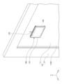
- FIG. 2A is a diagram showing the antenna device 100 attached to a window glass 11 from the indoor side.
- FIG. 2A shows the antenna device 100 and a window 10.
- the window 10 includes a window glass 11 and a window frame 12.
- FIG. 2B is a perspective view showing antenna device 100 from the outdoor side.
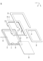
- FIG. 3A is a perspective view showing antenna device 100 in a disassembled state from the indoor side.
- FIG. 3B is a perspective view showing antenna device 100 in a disassembled state from the outdoor side.
- the window 10 (window glass 11 and window frame 12) is omitted from FIGS. 2B, 3A, and 3B.
- the antenna device 100 includes a housing 110, an antenna 120, a transmission cable 125, a holder 130, double-sided tape 140, a positioning jig 150, and a matching layer 160.
- the housing 110 is a case that holds the antenna 120.
- the housing 110 is fixed to the holder 130 when the antenna 120 is attached to the window glass 11.
- the holder 130 is attached to a main surface 11B2 (fourth main surface/see FIG. 1B ) of the glass plate 11B of the window glass 11 with double-sided tape 140.
- the housing 110 is not fixed to the holder 130 when the positioning jig 150 is inserted into the holder 130. After laser processing is performed on the low-e film 11C using the positioning jig 150, the housing 110 is fixed to the holder 130 with the matching layer 160 inserted into the holder 130.
- the housing 110 may be made of any insulating material, and is made of resin as an example.
- the housing 110 is a case that is rectangular in plan view and has a recess on the -Z side (see FIG. 3B) that is recessed toward the +Z direction.
- the antenna 120 is provided on the surface on the -Z side of the wall that is parallel to the XY plane at the bottom of the recess in the housing 110. In other words, the antenna 120 is provided within the recess in the housing 110.
- the antenna 120 may be attached to the housing 110 using double-sided tape, adhesive, or the like.
- the housing 110 has two protrusions 111 that protrude in the -Z direction from the side wall that surrounds the recess on the +X direction side.
- the two protrusions 111 are spaced apart in the Y direction.
- the protrusions 111 are provided to prevent the matching layer 160 inserted into the groove 131A of the holder 130 from slipping out when the housing 110 is attached to the holder 130.
- the protrusions 111 engage with the engagement portion 132A of the holder 130.
- the housing 110 also has insertion holes 112, as shown in Figures 3A and 3B.
- the housing 110 has four insertion holes 112.
- Figure 3A shows the two insertion holes 112 on the +Y direction side from the +Z direction side.
- Figure 3B shows the two insertion holes 112 on the -Y direction side from the -Z direction side.
- the four insertion holes 112 are formed near the four corners of the wall portion parallel to the XY plane at the bottom of the recess in the housing 110, and penetrate the wall portion parallel to the XY plane at the bottom of the recess in the housing 110 in the Z direction.
- Each insertion hole 112 is a slit-shaped hole portion that is long in the X direction and short in the Y direction when viewed in the XY plane, and the claw portion 133 of the holder 130 is inserted and engaged when the housing 110 is attached to the holder 130.
- the housing 110 may also be transparent. Transparent means that the visual transmittance is at least 40%, preferably 60% or more, more preferably 70% or more, and even more preferably 80% or more. Examples of resin materials that satisfy this condition include acrylic resins such as polymethyl methacrylate, cycloolefin resins, polycarbonate resins, and polyethylene terephthalate (PET).
- the housing 110 may also be made of transparent glass. The housing 110 being transparent can suppress obstruction of the view through the window glass 11.
- the antenna 120 is provided on the surface of the ⁇ Z direction side of the wall parallel to the XY plane at the bottom of the recess of the housing 110, for example.
- the antenna 120 transmits and receives radio waves to and from the base station BS located outside the window glass 11 (outdoor side/ ⁇ Z direction side), so it is sufficient that the antenna 120 has directivity toward the outside of the window glass 11.
- a patch antenna, a monopole antenna, or a dipole antenna can be used as the antenna 120.
- a plurality of antennas 120 may be provided to configure a phased array antenna for beamforming. In this case, a phase shifter may be provided for each antenna 120.
- a plurality of antennas 120 may be provided to configure a plurality of antennas for MIMO (Multi Input Multi Output) communication.
- MIMO Multi Input Multi Output
- a liquid crystal phase shifter may be provided on the +Z side of the antenna 120.
- the liquid crystal phase shifter may be provided on the surface on the -Z side of a wall parallel to the XY plane at the bottom of the recess in the housing 110, and multiple antennas 120 may be stacked on top of each other on the -Z side of the liquid crystal phase shifter.
- the liquid crystal phase shifter is used when the repeater 200 performs beamforming using multiple antennas 120 as a phased array antenna, but a phase shifter other than a liquid crystal phase shifter may be used instead of the liquid crystal phase shifter.
- liquid crystal phase shifters consume little power and generate little heat, they are preferable when installed on the window glass 11 in that they can suppress thermal cracking.
- the antenna 120 may also be transparent. In this case, it is preferable that the housing 110 is also transparent.
- Transparency means that the visual transmittance is at least 40%, preferably 60% or more, more preferably 70% or more, and even more preferably 80% or more.
- the antenna 120 When the antenna 120 is transparent, it is preferable to form it from a transparent conductive film such as zinc oxide (ZnO), tin oxide (SnO 2 ), tin-doped indium oxide (ITO), indium oxide-tin oxide (IZO), metal nitride such as titanium nitride (TiN) or chromium nitride (CrN), or a Low-e film for Low-e glass.
- the antenna 120 may also be formed from a thin metal film such as copper, nickel, or gold. In the case of a thin metal film, it is preferable to form it in a mesh shape from the viewpoint of visibility.
- the transmission cable 125 connects the antenna 120 of the antenna device 100 to the communication device 180. When there are multiple antennas 120, the transmission cable 125 may be connected to each antenna 120. As an example, the transmission cable 125 is configured with a coaxial cable. Note that, instead of a coaxial cable, a transmission path such as a waveguide or a microstrip line or a coplanar waveguide formed on a flexible substrate or the like may be used as the transmission cable 125.
- the holder 130 is a frame-shaped member in a plan view. More specifically, the frame shape of the holder 130 is a rectangular ring shape.
- the holder 130 has a base portion 131, a support portion 132, and a claw portion 133.
- the base 131 has a portion extending in the X direction on the +Y side, a portion extending in the Y direction on the -X side, and a portion extending in the X direction on the -Y side. These three portions of the base 131 correspond to the three sides of the rectangular ring-shaped shape of the holder 130.
- Two claws 133 are provided on each of the +Y side end of the portion of the base 131 extending in the X direction on the +Y side, and the -Y side end of the portion of the base 131 extending in the X direction on the -Y side. The claws 133 extend from the base 131 in the +Z direction.
- the base 131 has a groove 131A formed along the inner edge of the frame-shaped holder 130.
- the groove 131A is recessed from the inner edge side of the base 131 toward the outer edge side.
- the recessed shape of the groove 131A matches the shape of three sides of the positioning jig 150 and the matching layer 160 excluding one short side of the four sides in a plan view.
- the positioning jig 150 and the matching layer 160 have the same size in a plan view and the same thickness in the Z direction.
- the support portion 132 connects, in the Y direction, the end of the +X direction side of the portion of the base portion 131 that extends in the X direction on the +Y direction side, and the end of the +X direction side of the portion that extends in the X direction on the -Y direction side.
- the support portion 132 connects, in the Y direction, the end of the +X direction side of the portion of the base 131 that extends in the X direction on the +Y direction side, and the end of the +X direction side of the portion that extends in the X direction on the -Y direction side, on the +Z direction side of the groove portion 131A when viewed in the YZ plane.
- Two engaging portions 132A recessed toward the +X direction are provided at the end of the support portion 132 on the -X direction side between both ends in the Y direction.
- the two engaging portions 132A are provided with a gap in the Y direction and are formed to match the positions of the two protrusions 111 of the housing 110.
- the two protrusions 111 engage with the two engagement portions 132A, respectively.
- the two protrusions 111 are positioned on the +X direction side of the matching layer 160. This makes it possible to prevent the matching layer 160 from slipping out of the groove portion 131A in the +X direction.
- the claw portion 133 When the housing 110 is attached to the holder 130, the claw portion 133 is inserted into the insertion hole 112 of the housing 110, and the claw at the tip of the claw portion 133 protrudes from the insertion hole 112 in the +Z direction, so that the claw portion 133 engages with the insertion hole 112. In this way, the housing 110 can be fixed to the holder 130, and the antenna 120 can be attached to the window glass 11.
- the positioning jig 150 can be inserted all the way into the -X direction side of the groove 131A. Furthermore, if the opposite operation is performed, the positioning jig 150 can be removed from the groove 131A of the holder 130. In other words, the positioning jig 150 is detachable from the holder 130.
- inserting the positioning jig 150 all the way into the groove 131A of the holder 130 is referred to as attaching the positioning jig 150 to the holder 130.
- the matching layer 160 can be inserted all the way into the -X side of the groove portion 131A.
- the matching layer 160 can be removed from the groove portion 131A of the holder 130.
- the matching layer 160 is detachable from the holder 130.
- the groove portion 131A holds the matching layer 160 and the positioning jig 150 in a replaceable manner.
- inserting the matching layer 160 all the way into the groove portion 131A of the holder 130 is referred to as attaching the matching layer 160 to the holder 130.
- the positioning jig 150 is removably provided between the antenna 120 and the window glass 11 by the holder 130 as described above.
- the matching layer 160 is removably provided between the antenna 120 and the window glass 11 by the holder 130 as described above.
- the positioning jig 150 attached to the holder 130 laser processing is performed on the portion of the window glass 11 that overlaps with the antenna 120 when viewed from the front of the window glass 11, and then the positioning jig 150 is removed from the holder 130, the matching layer 160 is attached to the holder 130, and the housing 110 is fixed to the holder 130. In this way, the holder 130 can hold the positioning jig 150 and the matching layer 160 in a swappable manner.
- the configuration of the holder 130 is not limited to the configuration described above.
- the holder 130 may have any configuration as long as it is capable of holding the positioning jig 150 and the matching layer 160 in a replaceable manner.
- the holder 130 does not have to be configured to hold the positioning jig 150 and the matching layer 160 interchangeably, but may be configured to at least hold the positioning jig 150 in a detachable manner.
- the holder 130 does not have to be configured to allow the positioning jig 150 and the matching layer 160 to be interchangeable, and may be configured to hold both the positioning jig 150 and the matching layer 160.
- the holder 130 may have a groove portion into which the positioning jig 150 is inserted and a groove portion into which the matching layer 160 is inserted, and after laser processing is completed, the matching layer 160 may be inserted into the groove portion while the positioning jig 150 is left in place without being removed.
- the positioning jig 150 that is left in place without being removed may be used to position the antenna 120.
- the antenna device 100 does not need to include the holder 130 as long as the positioning jig 150 and matching layer 160 can be removably provided between the antenna 120 and the window glass 11.
- the positioning jig 150 may be fixed to the window glass 11 with double-sided tape or the like, laser processing may be performed, the positioning jig 150 may be removed from the window glass 11, and then the housing 110 to which the antenna 120 is attached may be fixed to the window glass 11 with double-sided tape 140 or the like.
- the antenna 120 may be positioned so that it is located in the irradiation area irradiated with the laser by marking or the like so that an operator can recognize the irradiation area of the low-e film 11C irradiated with the laser.
- the double-sided tape 140 has a shape and size corresponding to the base 131 of the holder 130 in a plan view.
- the double-sided tape 140 adheres the surface on the -Z direction side of the base 131 of the holder 130 to the main surface 11B2 (fourth main surface) of the glass plate 11B of the window glass 11.
- Fig. 2B shows a state in which the matching layer 160 is inserted into the holder 130. In this state, when the holder 130 is adhered to the main surface 11B2 (fourth main surface) of the glass plate 11B of the window glass 11 with the double-sided tape 140, the state shown in Fig. 2A is obtained.
- the positioning jig 150 is a jig that indicates the position of an irradiation area where a laser is irradiated on the Low-e film 11C of the window glass 11 during laser processing.
- the positioning jig 150 is detachably provided between the antenna 120 and the window glass 11 by the holder 130.
- the positioning jig 150 is, as an example, a frame-shaped metal jig when viewed from the front of the window glass 11, and has an inner edge 151 and an outer edge 152.
- the inside of the inner edge 151 of the positioning jig 150 forms an opening.
- the positioning jig 150 is opaque to the laser. "Opaque to the laser" means, for example, that the transmittance of the positioning jig 150 for a laser of the frequency used in laser processing is 10% or less, preferably 5% or less, more preferably 1% or less, and even more preferably 0.1% or less.
- the positioning jig 150 is opaque to the laser used in the laser processing, and the inner edge 151 is provided to define the irradiation area in which the laser is irradiated onto the low-e film 11C during the laser processing.
- the irradiation area will be described later with reference to Figures 4B and 4C.
- the inner edge 151 of the positioning jig 150 is larger than the outer edge of the antenna 120 attached to the holder 130 via the housing 110 when viewed from the front of the window glass 11, and includes the outer edge of the antenna 120.
- the inner edge 151 defines the irradiation area, and the portion of the low-e film 11C within the irradiation area becomes a low-loss section by being processed by laser processing to reduce the transmission loss of radio waves.
- the low-loss section is a section where the transmission loss of radio waves is reduced by dividing the low-e film 11C into a lattice shape or the like. Such a low-loss section is provided in the low-e film 11C in order to reduce the transmission loss of radio waves transmitted and received by the antenna 120.
- the area in which the antenna 120 is disposed be inside the irradiation area defined by the inner edge 151 when viewed from the front of the window glass 11.
- the housing 110 that holds the antenna 120 is attached to the holder 130 after the positioning jig 150 is removed from the holder 130, and it is desirable that the position of the area in which the antenna 120 is disposed be inside the irradiation area defined by the inner edge 151. This is because a low-loss portion is formed within the irradiation area.
- the inner edge 151 of the positioning jig 150 is larger than the outer edge of the antenna 120 attached to the holder 130 via the housing 110 when viewed from the front of the window glass 11, and is configured to include the outer edge of the antenna 120. This is so that the antenna 120 is positioned inside the low-loss portion of the Low-e film 11C when viewed from the front of the window glass 11. This is because, if there is a portion of the antenna 120 that protrudes from the low-loss portion of the Low-e film 11C when viewed from the front of the window glass 11, the transmission loss of radio waves in that portion will not be reduced.
- the irradiation area indicated by the inner edge 151 of the positioning jig 150 is located inside the outer edge of the housing 110.
- the low-loss portion formed within the irradiation area is divided by the laser processing, leaving thin linear scratches and looking unsightly.
- the irradiation area indicated by the inner edge 151 of the positioning jig 150 is located inside the outer edge of the housing 110.
- the positioning jig 150 may be located on the side from which the laser arrives and have a roughened surface. For example, if the laser is irradiated from the +Z direction during laser processing and the laser arrives at the positioning jig 150 from the +Z direction side, it is sufficient that at least the surface of the positioning jig 150 on the +Z direction side is roughened.
- the positioning jig 150 may be made of a material other than metal.
- a roughened surface is a surface with minute irregularities. Such a surface scatters the laser, which can increase the transmission loss of the laser, and can define the irradiation area in the same way as when a non-roughened metal frame-shaped positioning jig 150 is used.
- the intensity of the laser reflected by the surface of the positioning jig 150 can be reduced, preventing damage to equipment due to laser reflection. Roughening can be achieved by, for example, mechanical processing, physical processing, electrochemical processing, or chemical processing.
- the laser irradiation may be stopped by detecting the reflection of the laser by the positioning jig 150. In this way, it is possible to more accurately decoat only the irradiated area, and it is also possible to more reliably prevent laser irradiation of unnecessary areas.
- the matching layer 160 is attached to the holder 130 so as to be replaceable with the positioning jig 150.
- the matching layer 160 may be provided.
- the matching layer 160 adjusts the electrical length of the radio waves passing through the window glass 11 to match the impedance, thereby reducing the loss.
- such a matching layer 160 can be made of polycarbonate, acrylic, COP (cycloolefin polymer), PET (polyethylene terephthalate), polystyrene, glass, or the like.
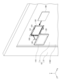
- FIG. 4A to 4D are diagrams for explaining an example of a method for installing the antenna device 100. More specifically, FIG. 4A is a diagram showing an example of a manner in which the holder 130 is attached to the window glass 11 with a double-sided tape 140. FIG. 4A also shows a positioning jig 150. FIG. 4B and FIG. 4C are diagrams showing an example of a state in which laser processing is performed using the positioning jig 150. FIG. 4D is a diagram showing an example of a state in which the matching layer 160 and the housing 110 are attached to the holder 130 after the laser processing is performed.
- the holder 130 is fixed to the main surface 11B2 of the window glass 11 with double-sided tape 140.
- the positioning jig 150 may be attached to the holder 130 after the holder 130 is fixed to the main surface 11B2 of the window glass 11, or the holder 130 may be fixed to the window glass 11 with the positioning jig 150 attached to the holder 130.
- the laser scanning device 50 is directed from the indoor side toward the irradiation area 155 indicated by the inner edge 151 of the positioning jig 150, and a laser 51 is irradiated from the laser scanning device 50.
- the irradiation area 155 indicates the area of the Low-e film 11C of the window glass 11 where a low-loss portion is to be formed by laser processing, as viewed from the front of the window glass 11.
- the laser 51 only the Low-e film 11C in the irradiated portion of the laser 51 is selectively removed, and the glass plates 11A and 11B of the window glass 11 are not removed.
- the low-loss portion of the Low-e film 11C is formed within the irradiation area 155.
- the laser 51 is reflected by the positioning jig 150.
- the positioning jig 150 is made of metal and therefore reflects the laser 51 without transmitting it. Since there is a certain width between the inner edge 151 and the outer edge 152 of the positioning jig 150, if the laser 51 is scanned by the laser scanning device 50 so that the laser 51 does not protrude outside the outer edge 152 during laser processing, a low-loss portion having an outer edge of approximately the same size as the outer edge of the irradiation area 155 can be formed. In laser processing, the laser 51 can be scanned over the entire irradiation area 155.
- the laser 51 can be irradiated only to the area where the low-loss portion is to be formed, so that irradiation of unnecessary areas such as the outside of the area where the low-loss portion is to be formed can be suppressed.
- laser processing may be performed on the low-e film 11C by directing the laser scanning device 50 from the outside toward the irradiation area 155 indicated by the inner edge 151 of the positioning jig 150 and irradiating the laser 51 from the laser scanning device 50.
- an antenna device 100 in which the antenna 120 is held by a housing 110 and attached to a holder 130 affixed to a window glass 11, and an installation method for the antenna device 100.
- the antenna 120 may be disposed within the line-of-sight area of the low-loss portion of the low-e film 11C without being held by the housing 110. That is, the antenna 120 may be disposed within the line-of-sight area of a portion (low-loss portion) of the window glass 11 from which at least a portion of the low-e film 11C has been removed. The antenna 120 may be disposed within the line-of-sight area of the low-loss portion, for example, on the wall 1W surrounding the window 10 or the frame of a bay window. The antenna 120 may also be disposed within the line-of-sight area of the low-loss portion, for example, while suspended from indoors.
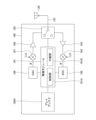
- Fig. 5 is a diagram showing an example of a circuit configuration of communication device 180.
- Fig. 5 shows a configuration of a portion corresponding to one antenna 120 in the entire configuration of communication device 180.
- Antenna 120 is connected to communication device 180.
- the communication device 180 may also be placed on the frame of a bay window, for example.
- the communication device 180 has an array antenna 180A, a wireless module 181, a switch 182, an LNA (Low Noise Amplifier) 183, a mixer 184, an ADC (Analog to Digital Converter) 185, a DAC (Digital to Analog Converter) 186, a mixer 187, and a PA (Power Amplifier) 188.
- LNA Low Noise Amplifier
- ADC Analog to Digital Converter
- DAC Digital to Analog Converter
- PA Power Amplifier
- the switch 182, LNA 183, mixer 184, ADC 185, DAC 186, mixer 187, and PA 188 of the communication device 180 are provided for each antenna 120.
- the communication device 180 includes the same number of components from the switch 182 to the PA 188 as the number of antennas 120.
- the wireless module 181 as an example, there is only one wireless module common to the multiple antennas 120.
- array antenna 180A is provided inside the housing of communication device 180.
- Array antenna 180A is an array antenna that communication device 180 uses when transmitting and receiving radio waves inside building 1.
- Array antenna 180A may also be provided outside the housing of communication device 180.
- Communication device 180 may also be configured to include a single antenna instead of multiple antennas arranged in an array like array antenna 180A.
- the wireless module 181 is composed of an MCU (Micro Controller Unit) as an example, and has a control unit 181A and a relay unit 181B that performs relay processing.
- the control unit 181A and the relay unit 181B are functional blocks that represent the functions executed by the MCU.
- the control unit 181A When receiving radio waves through the antenna 120, the control unit 181A switches the three-terminal switch 182 to connect the antenna 120 to the LNA 183. When transmitting radio waves through the antenna 120, the control unit 181A switches the three-terminal switch 182 to connect the antenna 120 to the PA 188.
- the relay unit 181B includes a Bluetooth (registered trademark) communication unit as an example, and is connected to the array antenna 180A, and transmits radio waves based on the digital signal input from the ADC 185 from the array antenna 180A to the inside of the building 1.
- the relay unit 181B transmits radio waves to the inside of the building 1 via the array antenna 180A, whereby the radio waves received by the antenna 120 from the base station BS are relayed and radiated to the inside of the building 1 in which the communication device 180 is located. This allows radio waves to be radiated over a wide area inside the building 1, making it easier for terminals such as the smartphone 30 located indoors to receive the radio waves.
- the communication unit that radiates the radio waves relayed by the relay unit 181B to the indoor side is not limited to Bluetooth, and may be Wi-Fi, etc.
- the relay unit 181B also performs relay processing on radio waves transmitted from an indoor terminal such as a smartphone 30 and received by the array antenna 180A, and outputs the radio waves to the DAC 186. This allows the array antenna 180A to radiate radio waves from a wide area inside the building 1, making it easier for indoor terminals such as a smartphone 30 to transmit radio waves.
- the LNA 183 is provided between the switch 182 and the mixer 184, and amplifies the radio waves received by the antenna 120 and outputs them while preventing degradation of the signal-to-noise ratio.
- the mixer 184 mixes the radio waves output from the LNA 183 with a local signal (LO), demodulates them, and outputs an IF (Intermediate Frequency) signal. By converting it to an IF signal, digital conversion can be easily performed by the ADC 185.
- LO local signal
- IF Intermediate Frequency
- the ADC 185 digitally converts the IF signal output from the mixer 184 and outputs it to the wireless module 181.
- the DAC 186 converts the signal output by the relay unit 181B into an analog signal and outputs the IF signal to the mixer 187.
- the mixer 187 mixes and modulates the IF signal with a local signal (LO) and outputs it to the PA 188.
- LO local signal
- the PA 188 amplifies the signal output from the mixer 187 and outputs it to the antenna 120 via the switch 182.
- communication device 180 may not include mixers 184 and 187.
- the signal input to ADC 185 and the signal output from DAC 186 are not IF signals, but signals in the Sub-6 frequency band.
- Fig. 6 is a diagram showing an example of the configuration of a positioning jig 150M according to a modified example of the embodiment. Although the holder 130 is omitted in Fig. 6, Fig. 6 shows an example of the configuration of the positioning jig 150M when the positioning jig 150M is attached to the holder 130, as viewed from the -Z direction side (the outside side) through the window glass 11.
- the positioning jig 150M is a metal plate-shaped jig having an outer edge 151M.
- the positioning jig 150M is made of metal and is opaque to the laser 51 of the frequency used for laser processing.
- the positioning jig 150M also has a frame-shaped mark 152M provided at a portion corresponding to the outer edge of the antenna 120 when viewed from the front from the -Z direction side of the window glass 11.
- the mark 152M may be a recess or the like provided on the surface on the -Z direction side of the positioning jig 150M made of a metal plate, or may be printed with a paint or the like that is more resistant to the laser 51 than the low-e film 11C.
- the positioning jig 150M may be made of different materials for the portion inside the mark 152M and the portion outside the mark 152M. In this case, if the difference in material results in a different appearance in terms of color, surface pattern, etc., it is not necessary to provide a recess or printed portion as the mark 152M.
- the laser scanning device 50 is placed on the outdoor side of the window glass 11, and the laser 51 is irradiated from the outdoor side of the window glass 11 onto the inside of the frame-shaped mark 152M. Since the laser 51 is irradiated from the surface side opposite the surface on which the housing 110 of the window glass 11 is provided, the plate-shaped positioning jig 150M can prevent the laser 51 from passing through to the surface side on which the housing 110 of the window glass 11 is provided.
- the laser irradiation can be stopped or started by detecting the difference in the reflection intensity of the laser. In this case, it is possible to more reliably decoat only the irradiated area.
- Antenna device 100 includes housing 110 attached to window glass 11 having Low-e film 11C, antenna 120 held by housing 110, and positioning jig 150 detachably provided between antenna 120 and window glass 11 and indicating the position of a laser irradiation area that removes at least a portion of Low-e film 11C (heat ray reflecting film). Use of positioning jig 150 allows an operator to accurately recognize the position of the portion of Low-e film 11C (heat ray reflecting film) to be removed.
- the antenna 120 may further include a matching layer 160 that is detachably provided between the antenna 120 and the window glass 11.
- a matching layer 160 that is detachably provided between the antenna 120 and the window glass 11.
- the matching layer 160 may be provided so as to be replaceable with the positioning jig 150.
- the matching layer 160 By providing the matching layer 160 so as to be replaceable with the positioning jig 150, it is easy to replace the positioning jig 150 with the matching layer 160, making it easier to install the antenna device 100.
- the housing 110 may further include a holder 130 (holding portion) that holds the housing 110 against the window glass 11, and the holder 130 (holding portion) may have a groove portion 131A that holds the matching layer 160 and the positioning jig 150 in a replaceable manner.
- the housing 110 that holds the antenna 120 can be stably attached to the window glass 11 by the holder 130.
- the positioning jig 150 and the matching layer 160 are replaceable in the groove portion 131A of the holder 130, it is easy to replace the positioning jig 150 with the matching layer 160 using the holder 130, making it easier to install the antenna device 100.
- the positioning jig 150 may be opaque to the laser 51. Because the positioning jig 150 blocks the laser 51, the positioning jig 150 can be used to accurately irradiate the laser 51 onto the irradiation area, making it possible to form a low-loss portion in the low-e film 11C (heat ray reflecting film) with high positional accuracy.
- the positioning jig 150 may also have a roughened surface located on the side from which the laser 51 arrives.
- the roughened surface scatters the laser 51, which can increase the transmission loss of the laser 51, and the irradiation area can be defined in the same way as when a non-roughened positioning jig 150 is used.
- the positioning jig 150 may also be made of metal. Since the laser 51 does not pass through the positioning jig 150 but is reflected by the positioning jig 150, it becomes possible to remove the heat ray reflective film on the window glass 11 with higher positional accuracy.
- the positioning jig 150 may also be frame-shaped when viewed from the front of the window glass 11.
- the frame shape can indicate the position of the laser irradiation area, making it easier to grasp the outer edge of the irradiation area and making it possible to remove the heat ray reflective film on the window glass 11 with higher positional accuracy.
- the inner edge 151 of the positioning jig 150 may be larger than the outer edge of the antenna 120 and may include the outer edge when viewed from the front of the window glass 11. Since the antenna 120 is located inside the low-loss portion of the low-e film 11C when viewed from the front of the window glass 11, it is possible to prevent the antenna 120 from protruding from the low-loss portion of the low-e film 11C, and it is possible to reliably reduce the transmission loss of radio waves.
- the irradiation area indicated by the inner edge of the positioning jig 150 may be located inside the outer edge of the housing 110. Since the low-loss portion formed within the irradiation area has thin linear scratches and is not visually appealing, by positioning the irradiation area inside the outer edge of the housing 110, it is possible to provide an antenna device 100 with a highly aesthetic appearance.
- the positioning jig 150M may also be plate-shaped. By using the plate-shaped positioning jig 150, the position of the portion of the low-e film 11C (heat ray reflecting film) to be removed can be accurately recognized, and an antenna device 100 can be provided that can remove the heat ray reflecting film from the window glass 11 with high positional accuracy.
- the positioning jig 150M may be made of different materials for the portion inside the portion corresponding to the outer edge of the antenna 120 when viewed from the front of the window glass 11 and the portion outside the portion. If the different materials result in different appearances such as color and surface pattern, it is possible to accurately identify the position of the portion of the low-e film 11C (heat ray reflecting film) to be removed without providing a recess or printed portion as the marker 152M, and it is possible to provide an antenna device 100 that can remove the heat ray reflecting film of the window glass 11 with high positional accuracy.
- the positioning jig 150M may also have a frame-shaped mark 152M provided at a portion that corresponds to the outer edge of the antenna 120 when viewed from the front of the window glass 11.
- the mark 152M By using the mark 152M, the position of the portion of the low-e film 11C (heat ray reflecting film) to be removed can be accurately identified, making it possible to provide an antenna device 100 that can remove the heat ray reflecting film of the window glass 11 with high positional accuracy.
- the antenna 120 may also be an antenna for the Sub-6 band or millimeter wave band. This makes it possible to provide an antenna device 100 that is capable of transmitting and receiving radio waves in frequency bands such as Sub-6 and the fifth generation mobile communication system (5G), and that can remove the heat ray reflecting film from the window glass 11 with high positional accuracy.
- 5G fifth generation mobile communication system
- the antenna 120 may be a patch antenna, a monopole antenna, a dipole antenna, an array antenna, or multiple antennas for MIMO communication. It is possible to provide an antenna device 100 that can remove the low-e film 11C (heat ray reflecting film) with high positional accuracy from the portion that overlaps the patch antenna, monopole antenna, dipole antenna, array antenna, or multiple antennas for MIMO communication with the window glass 11 when viewed from the front.
- the low-e film 11C heat ray reflecting film
- the antenna 120 may also be transparent. This allows for an antenna device 100 that is not conspicuous even when placed over the window glass 11 and does not impair visibility.
- antenna device 100 includes a positioning jig 150 that is detachably attached to a window glass 11 having a Low-e film 11C and indicates the position of an irradiation area of a laser that removes at least a portion of the Low-e film 11C, and an antenna 120 that is positioned within the line of sight of the portion of the window glass 11 from which at least a portion of the Low-e film 11C has been removed.
- a positioning jig 150 that is detachably attached to a window glass 11 having a Low-e film 11C and indicates the position of an irradiation area of a laser that removes at least a portion of the Low-e film 11C, and an antenna 120 that is positioned within the line of sight of the portion of the window glass 11 from which at least a portion of the Low-e film 11C has been removed.
- an antenna device 100 that is configured such that the antenna 120 is positioned within the line-of-sight area of the low-loss portion from which at least a portion of the low-e film 11C has been removed, and that allows the heat ray reflecting film of the window glass 11 to be removed with high positional accuracy.
- the antenna 120 does not need to be held by the housing 110, and may be positioned, for example, around the window 10 within the line-of-sight area.
- the repeater 200 includes the above-mentioned antenna device 100 and a communication device 180 that is connected to the antenna 120 and is arranged separately from the antenna 120 around the window where the window glass 11 is provided, and that performs wireless communication via the antenna 120.
- a communication device 180 that is connected to the antenna 120 and is arranged separately from the antenna 120 around the window where the window glass 11 is provided, and that performs wireless communication via the antenna 120.
- the window glass system 250 includes the above-mentioned antenna device 100 and a window glass 11 having a low-e film 11C.
- the positioning jig 150 it is possible to accurately identify the position of the portion of the low-e film 11C (heat ray reflecting film) to be removed.
- the antenna device installation method includes the steps of attaching the housing 110 to the window glass 11 having the Low-e film 11C provided on the window, installing a positioning jig 150 on the window glass 11, which indicates the position of the irradiation area of the laser that removes at least a portion of the Low-e film 11C, irradiating the laser using the positioning jig 150 to remove at least a portion of the Low-e film 11C within the irradiation area, and installing the antenna 120 within the line-of-sight area of the portion of the window glass 11 from which at least a portion of the Low-e film 11C has been removed.
- the positioning jig 150 it is possible to accurately recognize the position of the portion of the Low-e film 11C (heat ray reflecting film) to be removed.
- the positioning jig 150 is frame-shaped when viewed from the front of the window glass 11, and the area surrounded by the frame-shaped positioning jig 150 is the irradiation area of the laser 51, and the laser 51 may be irradiated from the surface side on which the housing 110 of the window glass 11 is provided. Since the laser 51 is irradiated from the surface side on which the housing 110 of the window glass 11 is provided, the position of the irradiation area of the laser 51 can be indicated by the frame shape, making it easier to grasp the outer edge of the irradiation area, and making it possible to remove the heat ray reflective film of the window glass 11 with higher positional accuracy.
- the positioning jig 150 may be opaque to the laser 51 and plate-shaped, and the laser may be irradiated to the irradiation area through the window glass 11. Since the laser 51 is irradiated from the surface side of the window glass 11 opposite the surface on which the housing 110 is provided, the plate-shaped positioning jig 150 can prevent the laser 51 from passing through to the surface side on which the housing 110 of the window glass 11 is provided.
Landscapes
- Chemical & Material Sciences (AREA)
- Engineering & Computer Science (AREA)
- Ceramic Engineering (AREA)
- Life Sciences & Earth Sciences (AREA)
- Chemical Kinetics & Catalysis (AREA)
- General Chemical & Material Sciences (AREA)
- Geochemistry & Mineralogy (AREA)
- Materials Engineering (AREA)
- Organic Chemistry (AREA)
- Support Of Aerials (AREA)
Priority Applications (1)
| Application Number | Priority Date | Filing Date | Title |
|---|---|---|---|
| JP2025518130A JPWO2024228350A1 (https=) | 2023-05-01 | 2024-04-24 |
Applications Claiming Priority (2)
| Application Number | Priority Date | Filing Date | Title |
|---|---|---|---|
| JP2023-075738 | 2023-05-01 | ||
| JP2023075738 | 2023-05-01 |
Publications (1)
| Publication Number | Publication Date |
|---|---|
| WO2024228350A1 true WO2024228350A1 (ja) | 2024-11-07 |
Family
ID=93333033
Family Applications (1)
| Application Number | Title | Priority Date | Filing Date |
|---|---|---|---|
| PCT/JP2024/016018 Ceased WO2024228350A1 (ja) | 2023-05-01 | 2024-04-24 | アンテナ装置、中継機、窓ガラスシステム、及び、アンテナ装置の設置方法 |
Country Status (2)
| Country | Link |
|---|---|
| JP (1) | JPWO2024228350A1 (https=) |
| WO (1) | WO2024228350A1 (https=) |
Citations (6)
| Publication number | Priority date | Publication date | Assignee | Title |
|---|---|---|---|---|
| JPH08292335A (ja) * | 1995-04-20 | 1996-11-05 | Fujikura Ltd | 光導波路作製方法 |
| JP2005012588A (ja) * | 2003-06-20 | 2005-01-13 | Nippon Sheet Glass Co Ltd | 車両用ガラスアンテナ装置 |
| JP2005089245A (ja) * | 2003-09-17 | 2005-04-07 | Central Glass Co Ltd | 合わせガラス |
| JP2006186488A (ja) * | 2004-12-27 | 2006-07-13 | Fujitsu Ten Ltd | 統合アンテナ |
| WO2011019001A1 (ja) * | 2009-08-11 | 2011-02-17 | 日本板硝子株式会社 | 統合アンテナ |
| WO2019026963A1 (ja) * | 2017-08-02 | 2019-02-07 | Agc株式会社 | ガラス用アンテナユニット、アンテナ付きガラス板、およびガラス用アンテナユニットの製造方法 |
-
2024
- 2024-04-24 JP JP2025518130A patent/JPWO2024228350A1/ja active Pending
- 2024-04-24 WO PCT/JP2024/016018 patent/WO2024228350A1/ja not_active Ceased
Patent Citations (6)
| Publication number | Priority date | Publication date | Assignee | Title |
|---|---|---|---|---|
| JPH08292335A (ja) * | 1995-04-20 | 1996-11-05 | Fujikura Ltd | 光導波路作製方法 |
| JP2005012588A (ja) * | 2003-06-20 | 2005-01-13 | Nippon Sheet Glass Co Ltd | 車両用ガラスアンテナ装置 |
| JP2005089245A (ja) * | 2003-09-17 | 2005-04-07 | Central Glass Co Ltd | 合わせガラス |
| JP2006186488A (ja) * | 2004-12-27 | 2006-07-13 | Fujitsu Ten Ltd | 統合アンテナ |
| WO2011019001A1 (ja) * | 2009-08-11 | 2011-02-17 | 日本板硝子株式会社 | 統合アンテナ |
| WO2019026963A1 (ja) * | 2017-08-02 | 2019-02-07 | Agc株式会社 | ガラス用アンテナユニット、アンテナ付きガラス板、およびガラス用アンテナユニットの製造方法 |
Also Published As
| Publication number | Publication date |
|---|---|
| JPWO2024228350A1 (https=) | 2024-11-07 |
Similar Documents
| Publication | Publication Date | Title |
|---|---|---|
| JP7830356B2 (ja) | 位相調整板、ガラス板、及び無線通信システム | |
| US11973260B2 (en) | Antenna | |
| US20250309551A1 (en) | Radio transmission system | |
| JP7383934B2 (ja) | 信号伝送装置及び信号伝送方法 | |
| WO2024228350A1 (ja) | アンテナ装置、中継機、窓ガラスシステム、及び、アンテナ装置の設置方法 | |
| JP6687454B2 (ja) | 無線基地局構造 | |
| WO2023157689A1 (ja) | 無線通信装置 | |
| WO2024262453A1 (ja) | アンテナ装置、及び、無線通信装置 | |
| WO2024262407A1 (ja) | アンテナ装置、及び、無線通信装置 | |
| WO2025047446A1 (ja) | アンテナ装置 | |
| WO2024171832A1 (ja) | 無線通信装置 | |
| JPH11163585A (ja) | 電磁波制御板 | |
| WO2024171893A1 (ja) | インターフェイス層の選択方法 | |
| WO2024116989A1 (ja) | アンテナ装置、及び、アンテナ装置の調整方法 | |
| WO2024248000A1 (ja) | アンテナ装置、及び、中継機 | |
| WO2025013703A1 (ja) | アンテナ装置及び無線通信装置 | |
| JP2025069512A (ja) | アンテナ装置、及び、無線通信装置 | |
| TWI832465B (zh) | 透光天線 | |
| KR100852426B1 (ko) | 무선통신 중계기 | |
| JPS58221503A (ja) | 電波反射装置 | |
| US12021295B2 (en) | Glazing unit with antenna unit | |
| JP2025002198A (ja) | アンテナ装置、及び、無線通信装置 | |
| WO2024143139A1 (ja) | 無線通信装置 | |
| EP4589769A1 (en) | Antenna device and antenna unit | |
| WO2024034421A1 (ja) | 無線通信装置 |
Legal Events
| Date | Code | Title | Description |
|---|---|---|---|
| 121 | Ep: the epo has been informed by wipo that ep was designated in this application |
Ref document number: 24800081 Country of ref document: EP Kind code of ref document: A1 |
|
| ENP | Entry into the national phase |
Ref document number: 2025518130 Country of ref document: JP Kind code of ref document: A |
|
| WWE | Wipo information: entry into national phase |
Ref document number: 2025518130 Country of ref document: JP |
|
| NENP | Non-entry into the national phase |
Ref country code: DE |