WO2024225163A1 - 反射型マスクブランク、反射型マスクブランクの製造方法、及び反射型マスクの製造方法 - Google Patents
反射型マスクブランク、反射型マスクブランクの製造方法、及び反射型マスクの製造方法 Download PDFInfo
- Publication number
- WO2024225163A1 WO2024225163A1 PCT/JP2024/015451 JP2024015451W WO2024225163A1 WO 2024225163 A1 WO2024225163 A1 WO 2024225163A1 JP 2024015451 W JP2024015451 W JP 2024015451W WO 2024225163 A1 WO2024225163 A1 WO 2024225163A1
- Authority
- WO
- WIPO (PCT)
- Prior art keywords
- film
- hard mask
- phase shift
- mask film
- reflective
- Prior art date
- Legal status (The legal status is an assumption and is not a legal conclusion. Google has not performed a legal analysis and makes no representation as to the accuracy of the status listed.)
- Ceased
Links
Images



Classifications
-
- G—PHYSICS
- G03—PHOTOGRAPHY; CINEMATOGRAPHY; ANALOGOUS TECHNIQUES USING WAVES OTHER THAN OPTICAL WAVES; ELECTROGRAPHY; HOLOGRAPHY
- G03F—PHOTOMECHANICAL PRODUCTION OF TEXTURED OR PATTERNED SURFACES, e.g. FOR PRINTING, FOR PROCESSING OF SEMICONDUCTOR DEVICES; MATERIALS THEREFOR; ORIGINALS THEREFOR; APPARATUS SPECIALLY ADAPTED THEREFOR
- G03F1/00—Originals for photomechanical production of textured or patterned surfaces, e.g., masks, photo-masks, reticles; Mask blanks or pellicles therefor; Containers specially adapted therefor; Preparation thereof
- G03F1/22—Masks or mask blanks for imaging by radiation of 100nm or shorter wavelength, e.g. X-ray masks, extreme ultraviolet [EUV] masks; Preparation thereof
- G03F1/24—Reflection masks; Preparation thereof
-
- G—PHYSICS
- G03—PHOTOGRAPHY; CINEMATOGRAPHY; ANALOGOUS TECHNIQUES USING WAVES OTHER THAN OPTICAL WAVES; ELECTROGRAPHY; HOLOGRAPHY
- G03F—PHOTOMECHANICAL PRODUCTION OF TEXTURED OR PATTERNED SURFACES, e.g. FOR PRINTING, FOR PROCESSING OF SEMICONDUCTOR DEVICES; MATERIALS THEREFOR; ORIGINALS THEREFOR; APPARATUS SPECIALLY ADAPTED THEREFOR
- G03F1/00—Originals for photomechanical production of textured or patterned surfaces, e.g., masks, photo-masks, reticles; Mask blanks or pellicles therefor; Containers specially adapted therefor; Preparation thereof
- G03F1/26—Phase shift masks [PSM]; PSM blanks; Preparation thereof
-
- G—PHYSICS
- G03—PHOTOGRAPHY; CINEMATOGRAPHY; ANALOGOUS TECHNIQUES USING WAVES OTHER THAN OPTICAL WAVES; ELECTROGRAPHY; HOLOGRAPHY
- G03F—PHOTOMECHANICAL PRODUCTION OF TEXTURED OR PATTERNED SURFACES, e.g. FOR PRINTING, FOR PROCESSING OF SEMICONDUCTOR DEVICES; MATERIALS THEREFOR; ORIGINALS THEREFOR; APPARATUS SPECIALLY ADAPTED THEREFOR
- G03F1/00—Originals for photomechanical production of textured or patterned surfaces, e.g., masks, photo-masks, reticles; Mask blanks or pellicles therefor; Containers specially adapted therefor; Preparation thereof
- G03F1/26—Phase shift masks [PSM]; PSM blanks; Preparation thereof
- G03F1/32—Attenuating PSM [att-PSM], e.g. halftone PSM or PSM having semi-transparent phase shift portion; Preparation thereof
-
- G—PHYSICS
- G03—PHOTOGRAPHY; CINEMATOGRAPHY; ANALOGOUS TECHNIQUES USING WAVES OTHER THAN OPTICAL WAVES; ELECTROGRAPHY; HOLOGRAPHY
- G03F—PHOTOMECHANICAL PRODUCTION OF TEXTURED OR PATTERNED SURFACES, e.g. FOR PRINTING, FOR PROCESSING OF SEMICONDUCTOR DEVICES; MATERIALS THEREFOR; ORIGINALS THEREFOR; APPARATUS SPECIALLY ADAPTED THEREFOR
- G03F1/00—Originals for photomechanical production of textured or patterned surfaces, e.g., masks, photo-masks, reticles; Mask blanks or pellicles therefor; Containers specially adapted therefor; Preparation thereof
- G03F1/38—Masks having auxiliary features, e.g. special coatings or marks for alignment or testing; Preparation thereof
- G03F1/48—Protective coatings
-
- G—PHYSICS
- G03—PHOTOGRAPHY; CINEMATOGRAPHY; ANALOGOUS TECHNIQUES USING WAVES OTHER THAN OPTICAL WAVES; ELECTROGRAPHY; HOLOGRAPHY
- G03F—PHOTOMECHANICAL PRODUCTION OF TEXTURED OR PATTERNED SURFACES, e.g. FOR PRINTING, FOR PROCESSING OF SEMICONDUCTOR DEVICES; MATERIALS THEREFOR; ORIGINALS THEREFOR; APPARATUS SPECIALLY ADAPTED THEREFOR
- G03F1/00—Originals for photomechanical production of textured or patterned surfaces, e.g., masks, photo-masks, reticles; Mask blanks or pellicles therefor; Containers specially adapted therefor; Preparation thereof
- G03F1/54—Absorbers, e.g. of opaque materials
-
- G—PHYSICS
- G03—PHOTOGRAPHY; CINEMATOGRAPHY; ANALOGOUS TECHNIQUES USING WAVES OTHER THAN OPTICAL WAVES; ELECTROGRAPHY; HOLOGRAPHY
- G03F—PHOTOMECHANICAL PRODUCTION OF TEXTURED OR PATTERNED SURFACES, e.g. FOR PRINTING, FOR PROCESSING OF SEMICONDUCTOR DEVICES; MATERIALS THEREFOR; ORIGINALS THEREFOR; APPARATUS SPECIALLY ADAPTED THEREFOR
- G03F1/00—Originals for photomechanical production of textured or patterned surfaces, e.g., masks, photo-masks, reticles; Mask blanks or pellicles therefor; Containers specially adapted therefor; Preparation thereof
- G03F1/68—Preparation processes not covered by groups G03F1/20 - G03F1/50
- G03F1/80—Etching
-
- H—ELECTRICITY
- H10—SEMICONDUCTOR DEVICES; ELECTRIC SOLID-STATE DEVICES NOT OTHERWISE PROVIDED FOR
- H10P—GENERIC PROCESSES OR APPARATUS FOR THE MANUFACTURE OR TREATMENT OF DEVICES COVERED BY CLASS H10
- H10P50/00—Etching of wafers, substrates or parts of devices
- H10P50/20—Dry etching; Plasma etching; Reactive-ion etching
- H10P50/24—Dry etching; Plasma etching; Reactive-ion etching of semiconductor materials
- H10P50/242—Dry etching; Plasma etching; Reactive-ion etching of semiconductor materials of Group IV materials
Definitions
- This disclosure relates to a reflective mask blank, a method for manufacturing a reflective mask blank, and a method for manufacturing a reflective mask.
- EUV extreme ultraviolet
- EUV includes soft X-rays and vacuum ultraviolet light, and specifically refers to light with a wavelength of approximately 0.2 nm to 100 nm. At present, EUV with a wavelength of approximately 13.5 nm is mainly being considered.
- a reflective mask In EUVL, a reflective mask is used.
- a reflective mask has, in this order, a substrate such as a glass substrate, a multilayer reflective film that reflects EUV light, a protective film that protects the multilayer reflective film, and an absorbing film that absorbs EUV light.
- the absorbing film may not only absorb EUV light, but also shift the phase of the EUV light. In other words, the absorbing film may be a phase shift film.
- An opening pattern is formed in the absorbing film.
- the opening pattern in the absorbing film is transferred to a target substrate such as a semiconductor substrate. Transferring includes reducing and transferring.
- the method for manufacturing a reflective mask described in Patent Document 1 includes transferring an opening pattern of a resist film to an etching mask film equivalent to a hard mask film, and transferring the opening pattern of the etching mask film to an absorbing film.
- the absorbing film contains at least one selected from iridium (Ir) and ruthenium (Ru).
- the etching mask film contains tantalum (Ta) or silicon (Si), and further contains at least one selected from oxygen (O), nitrogen (N), carbon (C), boron (B), and hydrogen (H).
- Noble metal elements are being considered as materials for the phase shift film.
- Examples of noble metal elements are Ir, Pt, Pd, Ag, and Au. These noble metal elements have a slow etching rate. Therefore, it is conceivable to thicken the hard mask film in order to ensure sufficient processing time when processing the phase shift film.
- the processing time for the hard mask film will be extended.
- the line width of the resist film may become narrower over time. This is because oxygen radicals etch the sides of the openings in the resist film when processing the hard mask film.
- the side of the opening in the hard mask film will become inclined. If a hard mask film with such an opening is used to process a phase shift film, the side of the opening in the phase shift film will also become inclined.
- One aspect of the present disclosure provides a technique for improving the processing accuracy of an opening pattern in a phase shift film.
- a reflective mask blank has a substrate, a multilayer reflective film, a protective film, a phase shift film, a first hard mask film, and a second hard mask film, in this order.
- the multilayer reflective film reflects EUV light.
- the protective film protects the multilayer reflective film from a first etching gas when the phase shift film is processed.
- the phase shift film absorbs EUV light and shifts the phase of the EUV light.
- the first hard mask film protects a portion of the phase shift film from the first etching gas when the phase shift film is processed.
- the second hard mask film protects a portion of the first hard mask film from a second etching gas when the first hard mask film is processed.
- the first hard mask film is more resistant to the first etching gas containing a fluorine-based gas than the phase shift film.
- the second hard mask film is more resistant to the second etching gas containing an oxygen-based gas and a chlorine-based gas than the first hard mask film.
- the second hard mask film and the first hard mask film have a selectivity (ER1/ER2) with respect to the second etching gas of 5 or more.
- the ER1 is the etching rate of the first hard mask film
- the ER2 is the etching rate of the second hard mask film.
- a second hard mask film is provided on the opposite side of the phase shift film with respect to the first hard mask film. This improves the processing accuracy of the opening pattern of the first hard mask film, and thus improves the processing accuracy of the opening pattern of the phase shift film.
- FIG. 1 is a cross-sectional view showing a reflective mask blank according to one embodiment.
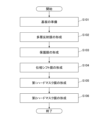
- FIG. 2 is a flowchart showing a method for manufacturing a reflective mask blank according to an embodiment.
- FIG. 3 is a cross-sectional view showing a reflective mask according to an embodiment.
- FIG. 4 is a flowchart showing a method for manufacturing a reflective mask according to an embodiment.
- FIG. 5(A) is a cross-sectional view showing an embodiment of a substrate preparation
- FIG. 5(B) is a cross-sectional view showing an embodiment of a second hard mask film at the end of processing
- FIG. 5(C) is a cross-sectional view showing an embodiment of a first hard mask film at the end of processing
- FIG. 5(A) is a cross-sectional view showing an embodiment of a substrate preparation
- FIG. 5(B) is a cross-sectional view showing an embodiment of a second hard mask film at the end of processing
- FIG. 5(C) is a cross-sectional
- FIG. 5(D) is a cross-sectional view showing an embodiment of a phase shift film at the end of processing.
- FIG. 6(A) is a cross-sectional view showing a conventional example of substrate preparation
- FIG. 6(B) is a cross-sectional view showing a conventional example during processing of a first hard mask film
- FIG. 6(C) is a cross-sectional view showing a conventional example at the completion of processing of the first hard mask film
- FIG. 6(D) is a cross-sectional view showing a conventional example during processing of a phase shift film
- FIG. 6(E) is a cross-sectional view showing a conventional example at the completion of processing of the phase shift film.
- FIG. 7 is a cross-sectional view showing an example of EUV light reflected by the reflective mask of FIG.
- FIG. 8 is an exaggerated cross-sectional view showing an example of the shape of the first hard mask film at the end of processing the first hard mask film.
- the X-axis direction, the Y-axis direction, and the Z-axis direction are mutually orthogonal.
- the Z-axis direction is perpendicular to the first major surface 10a of the substrate 10.
- the X-axis direction is perpendicular to the incidence surface of the EUV light (the surface including the incident light beam and the reflected light beam). As shown in FIG. 7, the incident light beam is inclined toward the Y-axis positive direction as it moves toward the Z-axis negative direction, and the reflected light beam is inclined toward the Y-axis positive direction as it moves toward the Z-axis positive direction.
- the reflective mask blank 1 has, for example, a substrate 10, a multilayer reflective film 11, a protective film 12, a phase shift film 13, a first hard mask film 14, and a second hard mask film 15, in this order.
- the multilayer reflective film 11, the protective film 12, the phase shift film 13, the first hard mask film 14, and the second hard mask film 15 are formed on the first main surface 10a of the substrate 10, in this order.
- the multilayer reflective film 11 reflects EUV light.
- the protective film 12 protects the multilayer reflective film 11 from the first etching gas when the phase shift film 13 is processed.
- the phase shift film 13 absorbs EUV light and shifts the phase of the EUV light.
- the first hard mask film 14 protects a part of the phase shift film 13 from the first etching gas when the phase shift film 13 is processed.
- the second hard mask film 15 protects a portion of the first hard mask film 14 from the second etching gas when the first hard mask film 14 is processed.
- the reflective mask blank 1 may further have a functional film not shown in FIG. 1.
- the reflective mask blank 1 may have a conductive film on the opposite side of the multilayer reflective film 11 with respect to the substrate 10.
- the conductive film is formed on the second main surface 10b of the substrate 10.
- the second main surface 10b is the surface facing opposite to the first main surface 10a.
- the conductive film is used, for example, to attach the reflective mask 2 to an electrostatic chuck of an exposure device.
- the reflective mask blank 1 may have a diffusion barrier film (not shown) between the multilayer reflective film 11 and the protective film 12. The diffusion barrier film suppresses the diffusion of metal elements contained in the protective film 12 into the multilayer reflective film 11.
- the reflective mask blank 1 may have a buffer film between the protective film 12 and the phase shift film 13, although this is not shown.
- the buffer film protects the protective film 12 from the first etching gas that forms the opening pattern 13a in the phase shift film 13.
- the buffer film is etched more slowly than the phase shift film 13. Unlike the protective film 12, the buffer film will ultimately have the same opening pattern as the opening pattern 13a of the phase shift film 13.
- the method for manufacturing a reflective mask blank 1 includes, for example, steps S101 to S106 shown in FIG. 2.
- step S101 a substrate 10 is prepared.
- step S102 a multilayer reflective film 11 is formed on a first main surface 10a of the substrate 10.
- step S103 a protective film 12 is formed on the multilayer reflective film 11.
- step S104 a phase shift film 13 is formed on the protective film 12.
- step S105 a first hard mask film 14 is formed on the phase shift film 13.
- a second hard mask film 15 is formed on the first hard mask film 14.
- the method for manufacturing a reflective mask blank 1 may further include a step of forming a functional film not shown in FIG. 2.
- the reflective mask 2 is produced, for example, using the reflective mask blank 1 shown in FIG. 1, and includes an opening pattern 13a in a phase shift film 13.
- the opening pattern 13a in the phase shift film 13 is transferred to a target substrate such as a semiconductor substrate. Transferring includes reducing and transferring. Note that the first hard mask film 14 and the second hard mask film 15 shown in FIG. 1 are not included in the reflective mask 2.
- a method for manufacturing a reflective mask 2 has steps S201 to S205 shown in Figure 4.
- a reflective mask blank 1 is prepared as shown in Figure 5(A).
- the reflective mask blank 1 includes a resist film 16 as shown in Figure 5(A).
- the resist film 16 is formed on a second hard mask film 15.
- An opening pattern to be transferred to the phase shift film 13 is formed in the resist film 16.
- step S202 as shown in FIG. 5B, the second hard mask film 15 is processed using a resist film 16 having an opening pattern.
- the second hard mask film 15 is exposed to a third etching gas, which etches the second hard mask film 15.
- the resist film 16 remains. As a result, the opening pattern of the resist film 16 is transferred to the second hard mask film 15.
- the third etching gas contains a fluorine-based gas.
- the fluorine-based gas contains at least one selected from, for example , CF4 gas, CHF3 gas, C2F6 gas, C3F6 gas , C4F6 gas, C4F8 gas, CH2F2 gas, CH3F gas , C3F8 gas, F2 gas, SF6 gas and NF3 gas.
- the third etching gas may contain an inert gas in addition to the fluorine-based gas.
- the inert gas contains at least one selected from, for example, N2 gas, He gas and Ar gas.
- the third etching gas preferably does not substantially contain an oxygen-based gas in order to suppress the line width W of the resist film 16 from becoming narrower.
- the oxygen-based gas is O2 gas, O3 gas or a mixture thereof.
- the content of the oxygen-based gas in the third etching gas is preferably 0.5% by volume or less.
- the third etching gas is preferably a plasma gas.
- step S203 the first hard mask film 14 is processed using the second hard mask film 15 having an opening pattern.
- the first hard mask film 14 is exposed to a second etching gas, which etches the first hard mask film 14.
- the second hard mask film 15 has a higher resistance to the second etching gas than the first hard mask film 14.
- the second hard mask film 15 remains. As a result, the opening pattern of the second hard mask film 15 is transferred to the first hard mask film 14.
- the second etching gas includes a chlorine-based gas and an oxygen-based gas.
- the chlorine-based gas includes at least one selected from, for example, Cl2 gas, SiCl4 gas, CHCl3 gas, CCl4 gas, and BCl3 gas.
- the oxygen-based gas includes at least one selected from, for example, O2 gas and O3 gas.
- the second etching gas may include an inert gas in addition to the chlorine-based gas and the oxygen-based gas.
- the inert gas includes at least one selected from, for example, N2 gas, He gas, and Ar gas.
- the second etching gas is preferably a plasma gas.
- the second hard mask film 15 may be removed.
- a fluorine-based gas is used for removing the second hard mask film 15 , similar to the third etching gas.
- the fluorine-based gas includes at least one selected from, for example , CF4 gas, CHF3 gas, C2F6 gas, C3F6 gas, C4F6 gas , C4F8 gas, CH2F2 gas, CH3F gas, C3F8 gas, F2 gas, SF6 gas, and NF3 gas .
- the fluorine - based gas may further include an inert gas .
- the fluorine-based gas is preferably a plasma gas.
- a chemical solution may be used for removing the second hard mask film 15.
- step S204 as shown in FIG. 5(D), the phase shift film 13 is processed using the first hard mask film 14 having an opening pattern.
- the phase shift film 13 is exposed to a first etching gas, which etches the phase shift film 13.
- the first hard mask film 14 has a higher resistance to the first etching gas than the phase shift film 13.
- the first hard mask film 14 remains. As a result, the opening pattern of the first hard mask film 14 is transferred to the phase shift film 13.
- the first etching gas includes a fluorine-based gas.
- the fluorine-based gas includes at least one selected from, for example, CF4 gas, CHF3 gas, C2F6 gas, C3F6 gas, C4F6 gas , C4F8 gas , CH2F2 gas , CH3F gas , C3F8 gas, F2 gas, SF6 gas, and NF3 gas.
- the first etching gas may include an active gas or an inert gas in addition to the fluorine-based gas.
- the active gas includes , for example, O2 gas.
- the inert gas includes, for example, at least one selected from N2 gas, He gas, and Ar gas.
- the first etching gas is preferably a plasma gas.
- step S205 although not shown, the first hard mask film 14 is removed.
- a fourth etching gas is used to remove the first hard mask film 14.
- the fourth etching gas contains a chlorine-based gas and an oxygen-based gas, similar to the second etching gas.
- the fourth etching gas may further contain an inert gas.
- the fourth etching gas is preferably a plasma.
- a chemical solution may be used to remove the first hard mask film 14.
- the conventional reflective mask blank 1 has a substrate 10, a multilayer reflective film 11, a protective film 12, a phase shift film 13, a first hard mask film 14, and a resist film 16, in that order.
- the conventional reflective mask blank 1 does not have a second hard mask film 15 between the first hard mask film 14 and the resist film 16.
- the phase shift film 13 preferably contains a precious metal element.
- the precious metal element is, for example, Ir, Pt, Pd, Ag, or Au. These precious metal elements have a relatively small refractive index, so the thickness of the phase shift film 13 can be reduced while maintaining the phase difference. However, these precious metal elements have a slow etching rate. Therefore, in order to ensure the processing time when processing the phase shift film 13, it is possible to thicken the first hard mask film 14.
- the processing time for processing the first hard mask film 14 will be extended.
- the line width W of the resist film 16 may become narrower over time when processing the first hard mask film 14. This is because oxygen radicals etch the side of the opening in the resist film 16 when processing the first hard mask film 14.
- the line width W of the resist film 16 narrows over time when processing the first hard mask film 14, causing the side of the opening in the first hard mask film 14 to become inclined. If the phase shift film 13 is processed using a first hard mask film 14 having such an opening, the side of the opening in the phase shift film 13 also becomes inclined, as shown in Figures 6(D) and 6(E).
- the first hard mask film 14 has a trapezoidal cross-sectional shape, as shown in FIG. 6(C). In locations where the first hard mask film 14 is thin, the first hard mask film 14 disappears earlier and etching of the phase shift film 13 begins earlier, as shown in FIG. 6(D), compared to locations where the first hard mask film 14 is thicker. As a result, the side surfaces of the opening in the phase shift film 13 also become inclined.
- the reflective mask blank 1 of the embodiment has a second hard mask film 15 between a first hard mask film 14 and a resist film 16.
- the second hard mask film 15 is processed using a resist film 16 having an opening pattern.
- the second hard mask film 15 is exposed to a third etching gas, which etches the second hard mask film 15. Since the third etching gas does not substantially contain an oxygen-based gas, oxygen radicals do not etch the sides of the openings in the resist film 16.
- the first hard mask film 14 can be processed using the second hard mask film 15 having an opening with vertical side surfaces, and it is possible to prevent the side surfaces of the openings in the first hard mask film 14 from inclining.
- the second hard mask film 15 has higher resistance to the second etching gas than the first hard mask film 14.
- the second hard mask film 15 and the first hard mask film 14 preferably have a selectivity (ER1/ER2) to the second etching gas of 5 or more.
- ER1 is the etching rate of the first hard mask film 14, and
- ER2 is the etching rate of the second hard mask film 15.
- the selectivity (ER1/ER2) is more preferably 10 or more, even more preferably 20 or more, particularly preferably 30 or more, and most preferably 50 or more.
- the selectivity (ER1/ER2) is preferably 1000 or less, more preferably 500 or less, and even more preferably 200 or less.
- the second etching gas is not particularly limited, but may contain, for example, 50% to 99% by volume of Cl2 gas and 1% to 50% by volume of O2 gas. Within this composition range, there may be at least one composition that has a selectivity (ER1/ER2) of 5 or more. Unlike the third etching gas, the second etching gas contains an oxygen-based gas.
- the selectivity (ER1/ER2) is 5 or more, it is possible to prevent the line width of the second hard mask film 15 from narrowing over time when processing the first hard mask film 14, and to prevent the side of the opening in the first hard mask film 14 from becoming inclined.
- FIG. 8 An example of the shape of the first hard mask film 14 at the end of processing of the first hard mask film 14 is shown in an exaggerated manner in Figure 8.
- the shape of the first hard mask film 14 can be evaluated from the taper angle ⁇ and the side etching amount E shown in Figure 8.
- the side etching amount is also called the undercut amount.
- the taper angle ⁇ is the angle between the boundary between the first hard mask film 14 and the phase shift film 13 and the side of the opening in the first hard mask film 14.
- the taper angle ⁇ is preferably 70° to 90°, and more preferably 80° to 90°. The larger the taper angle ⁇ , the more preferable it is, and it may be 90°.
- the side etching amount E is the shift amount of the side of the opening in the first hard mask film 14 relative to the side of the opening in the second hard mask film 15 at the boundary between the second hard mask film 15 and the first hard mask film 14.
- the side etching amount E is preferably 0 nm to 10 nm, and more preferably 0 nm to 5 nm. The smaller the side etching amount E, the more preferable, and it may be 0 nm.
- the phase shift film 13 can be processed using the first hard mask film 14 having an opening with vertical sides as shown in FIG. 5(D), and the side of the opening in the phase shift film 13 can be prevented from being inclined. Therefore, the processing accuracy of the opening pattern in the phase shift film 13 can be improved.
- the first hard mask film 14 has higher resistance to the first etching gas than the phase shift film 13.
- the first hard mask film 14 and the phase shift film 13 have a selectivity ratio (ER3/ER4) to the first etching gas of 2 or more.
- ER3 is the etching rate of the phase shift film 13
- ER4 is the etching rate of the first hard mask film 14.
- the selectivity ratio (ER3/ER4) is more preferably 3 or more, and even more preferably 4 or more.
- the selectivity ratio (ER3/ER4) is preferably 1000 or less.
- the first etching gas is not particularly limited, but may contain, for example, 50% to 99% by volume of CF4 gas and 1% to 50% by volume of O2 gas. In this composition range, there may be at least one composition that has a selectivity ratio (ER3/ER4) of 2 or more.
- the first etching gas may contain an oxygen-based gas, unlike the third etching gas.
- the selection ratio (ER3/ER4) is 2 or more, it is possible to prevent the line width of the first hard mask film 14 from narrowing over time during processing of the phase shift film 13, and to prevent the side of the opening in the phase shift film 13 from becoming inclined.
- the first hard mask film 14 preferably contains, as a metal element, an element X1 whose fluoride has a valence of 4 or less and a melting point T1 of 250°C or more. If the melting point T1 is 250°C or more, the etching rate ER4 of the first hard mask film 14 is slow, the selectivity ratio (ER3/ER4) is sufficiently large, and the phase shift film 13 is easily processed.
- the melting point T1 is preferably 3000°C or less. Table 1 shows the melting points of fluorides under atmospheric pressure.
- element X1 contains at least one element selected from Cr, Ru, Al and Hf.
- the etching rate ER4 of the first hard mask film 14 containing these elements is slow, the selectivity (ER3/ER4) is sufficiently large, and the phase shift film 13 can be easily processed.
- the first hard mask film 14 may contain a compound of element X1.
- the compound of element X1 contains, for example, at least one element selected from O, N, C, and B. By adding at least one element selected from O, N, C, and B, crystallization of the first hard mask film 14 can be suppressed, and the roughness of the opening side surface of the first hard mask film 14 can be reduced.
- Cr as element X1 increases the amount of side etching E, it is preferable to use it as a Cr compound containing a metal element or a nonmetal element other than Cr.
- the thickness t1 of the first hard mask film 14 is preferably 5 nm to 40 nm. If the thickness t1 of the first hard mask film 14 is 5 nm or more, a sufficient amount of the first hard mask film 14 remains when processing of the phase shift film 13 is completed. If the thickness t1 of the first hard mask film 14 is 40 nm or less, the first etching gas easily enters the openings of the first hard mask film 14, and the phase shift film 13 is easily etched.
- the second hard mask film 15 preferably contains, as a metal element or semi-metal element, an element X2 whose oxide has a melting point T2 of 1000°C or higher. If the melting point T2 is 1000°C or higher, the etching rate ER2 of the second hard mask film 15 is slow, the selectivity (ER1/ER2) is sufficiently large, and the first hard mask film 14 is easily processed.
- the melting point T2 is preferably 3000°C or lower. Table 2 shows the melting points of oxides under atmospheric pressure.
- the element X2 contains at least one element selected from Ta, Si, Ti, W, Sn, and Nb.
- the etching rate ER2 of the second hard mask film 15 containing these elements is slow, the selectivity (ER1/ER2) is sufficiently large, and the first hard mask film 14 is easily processed. It is more preferable that the element X2 contains at least one element selected from Ta, Ti, W, Sn, and Nb.
- the second hard mask film 15 may contain a compound of element X2.
- the compound of element X2 contains, for example, at least one element selected from O, N, C, and B. By adding at least one element selected from O, N, C, and B, crystallization of the second hard mask film 15 can be suppressed, and the roughness of the side surface of the opening in the second hard mask film 15 can be reduced.
- Table 3 shows an example of the relationship between the chemical composition (volume ratio) of the second etching gas, the chemical composition (molar ratio) of the first hard mask film 14, the chemical composition (molar ratio) of the second hard mask film 15, and the selectivity ratio (ER1/ER2).
- the selectivity ratios (ER1/ER2) shown in Table 3 are all 10 or more.
- the thickness t2 of the second hard mask film 15 is preferably 2 nm to 20 nm. If the thickness t2 of the second hard mask film 15 is 2 nm or more, a sufficient amount of the second hard mask film 15 remains when processing of the first hard mask film 14 is completed. If the thickness t2 of the second hard mask film 15 is 20 nm or less, the second etching gas easily enters the openings of the second hard mask film 15, and the first hard mask film 14 is easily etched.
- the ratio (t1/t2) of the thickness (t1) of the first hard mask film 14 to the thickness (t2) of the second hard mask film 15 is preferably 1 to 40. If the ratio (t1/t2) is 1 or more, the thickness (t2) of the second hard mask film 15 is sufficiently thin, and the processing time during processing of the second hard mask film 15 can be short. If the ratio (t1/t2) is 40 or less, the thickness (t1) of the first hard mask film 14 is sufficiently thin, and the processing time during processing of the first hard mask film 14 can be shortened, and there is little concern that the pattern end of the second hard mask film 15 will be scraped off.
- the ratio (t1/t2) is more preferably 2 to 10, even more preferably 2.5 to 10, and particularly preferably 3 to 10.
- the substrate 10, the multilayer reflective film 11, the protective film 12, and the phase shift film 13 will be described in that order.
- the first hard mask film 14 and the second hard mask film 15 are as described above.
- the substrate 10 is, for example, a glass substrate.
- the material of the substrate 10 is preferably quartz glass containing TiO 2. Quartz glass has a smaller linear expansion coefficient and a smaller dimensional change due to temperature change than general soda-lime glass. Quartz glass may contain 80% to 95% by mass of SiO 2 and 4% to 17% by mass of TiO 2. When the TiO 2 content is 4% to 17% by mass, the linear expansion coefficient is approximately zero near room temperature, and there is almost no dimensional change near room temperature. Quartz glass may contain a third component or impurity other than SiO 2 and TiO 2.
- the material of the substrate 10 may be crystallized glass in which a ⁇ -quartz solid solution is precipitated, silicon, metal, or the like.
- the substrate 10 has a first main surface 10a and a second main surface 10b facing opposite to the first main surface 10a.
- a multilayer reflective film 11 and the like are formed on the first main surface 10a.
- the size of the substrate 10 in plan view is, for example, 152 mm long and 152 mm wide.
- the vertical and horizontal dimensions may be 152 mm or more.
- the first main surface 10a and the second main surface 10b each have, for example, a square quality assurance area in the center.
- the size of the quality assurance area is, for example, 142 mm long and 142 mm wide.
- the quality assurance area of the first main surface 10a preferably has a root-mean-square roughness (Rq) of 0.15 nm or less and a flatness of 100 nm or less. In addition, it is preferable that the quality assurance area of the first main surface 10a does not have any defects that cause phase defects.
- the multilayer reflective film 11 reflects EUV light.
- the multilayer reflective film 11 is, for example, a laminate of alternating high-refractive index layers and low-refractive index layers.
- the high-refractive index layers are made of, for example, silicon (Si)
- the low-refractive index layers are made of, for example, molybdenum (Mo), so a Mo/Si multilayer reflective film is used.
- Ru/Si multilayer reflective film, Mo/Be multilayer reflective film, Mo compound/Si compound multilayer reflective film, Si/Mo/Ru multilayer reflective film, Si/Mo/Ru/Mo multilayer reflective film, Si/Ru/Mo/Ru multilayer reflective film, Si/Ru/Mo multilayer reflective film, and Si/Ru/Mo multilayer reflective film can also be used as the multilayer reflective film 11.
- each layer constituting the multilayer reflective film 11 and the number of repeat units of the layers can be appropriately selected depending on the material of each layer and the reflectivity to EUV light.
- the multilayer reflective film 11 is a Mo/Si multilayer reflective film, in order to achieve a reflectivity of 60% or more for EUV light with an incident angle ⁇ (see FIG. 7) of 6°, Mo layers with a thickness of 2.3 ⁇ 0.1 nm and Si layers with a thickness of 4.5 ⁇ 0.1 nm can be stacked so that the number of repeat units is 30 or more and 60 or less. It is preferable that the multilayer reflective film 11 has a reflectivity of 60% or more for EUV light with an incident angle ⁇ of 6°. The reflectivity is more preferably 65% or more.
- the method for forming each layer constituting the multilayer reflective film 11 is, for example, a DC sputtering method, a magnetron sputtering method, an ion beam sputtering method, etc.
- a DC sputtering method a DC sputtering method
- a magnetron sputtering method a magnetron sputtering method
- an ion beam sputtering method etc.
- an example of the film formation conditions for each of the Mo layer and the Si layer is as follows. ⁇ Si layer deposition conditions> Target: Si target, Sputtering gas: Ar gas, Gas pressure: 1.3 ⁇ 10 ⁇ 2 Pa to 2.7 ⁇ 10 ⁇ 2 Pa, Ion acceleration voltage: 300V to 1500V, Film formation rate: 0.030 nm/sec to 0.300 nm/sec, Si layer thickness: 4.5 ⁇ 0.1 nm.
- the protective film 12 is formed between the multilayer reflective film 11 and the phase shift film 13, and protects the multilayer reflective film 11.
- the protective film 12 protects the multilayer reflective film 11 from the first etching gas when the phase shift film 13 is processed, that is, in step S204.
- the protective film 12 is not removed even when exposed to the first etching gas, but remains on the multilayer reflective film 11.
- the protective film 12 contains at least one element selected from, for example, Ru, Rh, and Si. When the protective film 12 contains Rh, it may contain only Rh, but it may also contain an Rh compound.
- the Rh compound may contain, in addition to Rh, at least one element Z1 selected from Ru, Nb, Mo, Ta, Ir, Pd, Zr, Y, and Ti.
- the extinction coefficient can be reduced while suppressing an increase in the refractive index, and the reflectance to EUV light can be improved. Furthermore, by adding Ta, Ir, Pd or Y to Rh, the resistance to the first etching gas can be improved.
- the Rh compound may contain, in addition to Rh, at least one element Z2 selected from N, O, C, and B.
- the element Z2 reduces the resistance of the protective film 12 to the first etching gas, but improves the smoothness of the protective film 12 by reducing the crystallinity of the protective film 12.
- the Rh compound containing the element Z2 has an amorphous structure or a microcrystalline structure. When the Rh compound has an amorphous structure or a microcrystalline structure, the X-ray diffraction profile of the Rh compound does not have a clear peak.
- the protective film 12 may be a film consisting of a single layer, or may be a multi-layer film having a lower layer and an upper layer.
- the lower layer of the protective film 12 is a layer formed in contact with the uppermost surface of the multilayer reflective film 11.
- the upper layer of the protective film 12 is in contact with the lowermost surface of the phase shift film 13. In this way, by forming the protective film 12 into a multi-layer structure, materials with excellent predetermined functions can be used for each layer, making it possible to make the entire protective film 12 multifunctional.
- the upper layer of the protective film 12 preferably contains Rh, and more preferably contains an Rh compound.
- the lower layer of the protective film 12 preferably contains at least one element selected from Ru, Nb, Mo, Zr, Y, C, and B, and more preferably contains Ru.
- the thickness of the protective film 12 described below means the total thickness of the multilayer film.
- the thickness of the protective film 12 is preferably 1.0 nm to 4.0 nm, more preferably 2.0 nm to 3.5 nm, and even more preferably 2.5 nm to 3.0 nm. If the thickness of the protective film 12 is 1.0 nm or more, the etching resistance is good. Furthermore, if the thickness of the protective film 12 is 4.0 nm or less, the reflectance to EUV light is good.
- the density of the protective film 12 is preferably 10.0 g/cm 3 to 14.0 g/cm 3. If the density of the protective film 12 is 10.0 g/cm 3 or more, the etching resistance is good. Furthermore, if the density of the protective film 12 is 14.0 g/cm 3 or less, the decrease in reflectance for EUV light can be suppressed.
- the top surface of the protective film 12, i.e., the surface of the protective film 12 on which the phase shift film 13 is formed, preferably has a root-mean-square roughness Rq of 0.20 nm or less, more preferably 0.17 nm or less. If the root-mean-square roughness Rq is 0.20 nm or less, the phase shift film 13 and the like can be formed smoothly on the protective film 12. In addition, scattering of EUV light can be suppressed, and the reflectance for EUV light can be improved.
- the root-mean-square roughness Rq is preferably 0.05 nm or more.
- the method for forming the protective film 12 is, for example, DC sputtering, magnetron sputtering, ion beam sputtering, etc.
- the Rh film is formed by DC sputtering
- an example of the film formation conditions is as follows. ⁇ Conditions for forming Rh film> Target: Rh target, Sputtering gas: Ar gas, Gas pressure: 1.0 ⁇ 10 ⁇ 2 Pa to 1.0 ⁇ 10 0 Pa, Target power density: 1.0 W/cm 2 to 8.5 W/cm 2 , Film formation rate: 0.020 nm/sec to 1.000 nm/sec, Film thickness: 1 nm to 10 nm.
- the phase shift film 13 is a film in which an opening pattern 13a is to be formed.
- the opening pattern 13a is not formed in the manufacturing process of the reflective mask blank 1, but is formed in the manufacturing process of the reflective mask 2.
- the phase shift film 13 shifts the phase of the second EUV light L2 relative to the first EUV light L1 shown in FIG. 7.
- the first EUV light L1 is light that passes through the opening pattern 13a without passing through the phase shift film 13, is reflected by the multilayer reflective film 11, and passes through the opening pattern 13a without passing through the phase shift film 13 again.
- the second EUV light L2 is light that passes through the phase shift film 13 while being absorbed by the phase shift film 13, is reflected by the multilayer reflective film 11, and passes through the phase shift film 13 while being absorbed by the phase shift film 13 again.
- the phase difference ( ⁇ 0) between the first EUV light L1 and the second EUV light L2 is, for example, 170° to 250°.
- the phase of the first EUV light L1 may be ahead of or behind the phase of the second EUV light L2.
- the phase shift film 13 uses the interference between the first EUV light L1 and the second EUV light L2 to improve the contrast of the transferred image.
- the transferred image is an image of the opening pattern 13a of the phase shift film 13 transferred onto the target substrate.
- the so-called projection effect occurs.
- the shadowing effect is caused by the fact that the incident angle ⁇ of the EUV light is not 0° (for example, 6°), and therefore an area where the sidewall blocks the EUV light occurs near the sidewall of the opening pattern 13a, causing a positional or dimensional shift in the transferred image.
- it is effective to lower the height of the sidewall of the opening pattern 13a, and it is also effective to thin the phase shift film 13.
- the thickness of the phase shift film 13 is, for example, 60 nm or less, and preferably 50 nm or less, in order to reduce the shadowing effect.
- the thickness of the phase shift film 13 is preferably 20 nm or more, and more preferably 30 nm or more, in order to ensure the phase difference between the first EUV light L1 and the second EUV light L2.
- phase shift film 13 In order to reduce the thickness of the phase shift film 13 to reduce the shadowing effect while maintaining the phase difference between the first EUV light L1 and the second EUV light L2, it is effective to reduce the refractive index n of the phase shift film 13. Also, in order to reduce the reflectance for EUV light, it is effective to increase the extinction coefficient k of the phase shift film 13. Thus, the phase shift film 13 is required to have excellent optical properties.
- the refractive index n of the phase shift film 13 is preferably 0.940 or less, more preferably 0.930 or less, even more preferably 0.929 or less, particularly preferably 0.925 or less, even more particularly preferably 0.920 or less, even more particularly preferably 0.918 or less, even more preferably 0.910 or less, and most preferably 0.900 or less.
- the refractive index n of the phase shift film 13 is preferably 0.885 or more.
- the refractive index is the refractive index for EUV light (e.g., light with a wavelength of 13.5 nm).
- the extinction coefficient k of the phase shift film 13 is preferably 0.030 or more, more preferably 0.034 or more, even more preferably 0.036 or more, and particularly preferably 0.038 or more.
- the extinction coefficient k of the phase shift film 13 is preferably 0.065 or less.
- the extinction coefficient is the extinction coefficient for EUV light (e.g., light with a wavelength of 13.5 nm).
- phase shift film 13 optical index n and extinction coefficient k are taken from the database of the Center for X-Ray Optics, Lawrence Berkeley National Laboratory, or values calculated from the "incident angle dependence" of reflectance, which will be described later.
- the incident angle ⁇ of the EUV light, the reflectance R for the EUV light, the refractive index n of the phase shift film 13, and the extinction coefficient k of the phase shift film 13 satisfy the following formula (1).
- R
- a number of combinations of the incident angle ⁇ and the reflectance R are measured, and the refractive index n and the extinction coefficient k are calculated by the least squares method so that the error between the multiple measurement data and equation (1) is minimized.
- the phase shift film 13 preferably contains a precious metal element.
- the precious metal element is, for example, Ir, Pt, Pd, Ag, or Au. These precious metal elements have a relatively small refractive index, so the thickness of the phase shift film 13 can be reduced while maintaining the phase difference. However, these precious metal elements have a slow etching rate. Therefore, in this embodiment, a first hard mask film 14 and a second hard mask film 15 are formed in this order on the phase shift film 13.
- the phase shift film 13 preferably has a layer made of an Ir-based material.
- the phase shift film 13 is a single layer, but may be a multi-layer film. In any case, it is preferable that at least one layer constituting the phase shift film 13 is made of an Ir-based material.
- the Ir-based material is a material containing Ir as a main component.
- the Ir-based material preferably contains 25 at% to 100 at% Ir, more preferably contains 30 at% to 100 at% Ir, even more preferably contains 40 at% to 100 at% Ir, and particularly preferably contains 50 at% to 100 at% Ir.
- the Ir-based material may be simple Ir, but is preferably an Ir compound.
- the Ir compound preferably contains at least one element selected from O, B, C, and N. By adding at least one element selected from O, B, C, and N, it is possible to suppress crystallization while suppressing deterioration of optical properties, and to reduce roughness on the side surface of the opening pattern 13a.
- the Ir compound preferably contains O, and more preferably contains O and N.
- the reflective mask 2 may be exposed to hydrogen gas.
- Hydrogen gas is used, for example, to reduce carbon contamination. Therefore, the phase shift film 13 may be exposed to hydrogen gas.
- O, B, C, or N contained in the Ir compound may react with hydrogen gas to generate hydrides (e.g., H2O ).
- hydrides e.g., H2O
- the hydrides are highly volatile, and O, B, C, or N is desorbed from the Ir compound, resulting in a decrease in the thickness of the phase shift film 13. A change in the film thickness leads to a change in the phase difference.
- the Ir compound contains at least one element selected from Ta, Cr, Mo, W, Re, and Si.
- the element selected from Ta, Cr, Mo, W, Re, and Si By adding these elements, hydrogen resistance can be improved.
- Ta, Cr, W, and Re can improve hydrogen resistance while suppressing deterioration of optical properties.
- Mo and Si can further improve hydrogen resistance.
- the method for forming the phase shift film 13 is, for example, DC sputtering, magnetron sputtering, or ion beam sputtering.
- the oxygen content of the phase shift film 13 can be controlled by the content of O2 gas in the sputtering gas.
- the nitrogen content of the phase shift film 13 can be controlled by the content of N2 gas in the sputtering gas.
- an example of the film formation conditions is as follows. ⁇ Deposition conditions of IrTaON film> Target: Ir target and Ta target (or IrTa target), Power density of Ir target: 1.0 W/cm 2 to 8.5 W/cm 2 , Power density of Ta target: 1.0 W/cm 2 to 8.5 W/cm 2 , Sputtering gas: a mixture of Ar gas, O2 gas, and N2 gas; Volume ratio of O2 gas in the sputtering gas ( O2 /(Ar+ O2 + N2 )): 0.01 to 0.25, Volume ratio of N2 gas in the sputtering gas ( N2 /(Ar+ O2 + N2 )): 0.01 to 0.25, Film formation rate: 0.020 nm/sec to 0.060 nm/sec, Film thickness: 20 nm to 60 nm.
- the protective film 12 has higher resistance to the first etching gas than the phase shift film 13.
- the selectivity ratio (ER3/ER5) of the protective film 12 and the phase shift film 13 to the first etching gas is preferably 5 or more.
- ER3 is the etching rate of the phase shift film 13
- ER5 is the etching rate of the protective film 12.
- the selectivity ratio (ER3/ER5) is preferably 5.0 or more, more preferably 10 or more, and even more preferably 30 or more.
- the selectivity ratio (ER3/ER5) is preferably 200 or less, and more preferably 100 or less.
- Example 1 a reflective mask blank 1 having a second hard mask film 15 between a first hard mask film 14 and a resist film 16 was prepared as shown in FIG. 5(A), and the second hard mask film 15 (step S202) and the first hard mask film 14 (step S203) were processed.
- Example 3 a reflective mask blank 1 not having a second hard mask film 15 was prepared as shown in FIG. 6(A), and the first hard mask film 14 was processed (step S203). After step S203 and before step S204, the cross section was observed with a SEM (Scanning Electron Microscope) to measure the side etching amount E and taper angle ⁇ .
- SEM Sccanning Electron Microscope
- a SiO 2 -TiO 2 type glass substrate (6 inch (152 mm) square outer shape, 6.3 mm thick) was prepared.
- This glass substrate had a thermal expansion coefficient of 0.02 ⁇ 10 -7 /°C at 20°C, a Young's modulus of 67 GPa, a Poisson's ratio of 0.17, and a specific rigidity of 3.07 ⁇ 10 7 m 2 /s 2.
- the quality assurance area of the first main surface 10a of the substrate 10 was polished to have a root-mean-square roughness (Rq) of 0.15 nm or less and a flatness of 100 nm or less.
- a 100 nm thick Cr film was formed on the second main surface 10b of the substrate 10 by magnetron sputtering. The sheet resistance of the Cr film was 100 ⁇ / ⁇ .
- a Mo/Si multilayer reflective film was formed as the multilayer reflective film 11.
- the Mo/Si multilayer reflective film was formed by repeating the deposition of a Si layer (film thickness 4.5 nm) and a Mo layer (film thickness 2.3 nm) 40 times using an ion beam sputtering method.
- the total film thickness of the Mo/Si multilayer reflective film was 272 nm ((4.5 nm + 2.3 nm) x 40).
- Rh film (thickness 5 nm) was formed as the protective film 12.
- the Rh film was formed using the ion beam sputtering method.
- An IrTaON film (35 nm thick) was formed as the phase shift film 13.
- the IrTaON film was formed using a two-target sputtering method.
- the chemical composition of the IrTaON film was measured using an X-ray photoelectron spectrometer (PHI 5000 VersaProbe) manufactured by ULVAC-PHI.
- the chemical composition (molar ratio) of the IrTaON film was Ir:Ta:O:N 71.4:6.1:20.5:2.0.
- a Cr film was formed as the first hard mask film 14.
- the Cr film was formed using a magnetron sputtering method.
- the thickness of the Cr film in Example 1 was 25 nm
- the thickness of the Cr film in Example 3 was 20 nm.
- a RuCr film was formed as the first hard mask film 14.
- the RuCr film was formed using a binary sputtering method.
- the chemical composition (molar ratio) of the RuCr film was Ru:Cr 60:40.
- the thickness of the RuCr film was 25 nm.
- a TaON film (thickness 5 nm) was formed as the second hard mask film 15.
- the TaON film was formed using a reactive sputtering method.
- the chemical composition of the TaON film was measured using an X-ray photoelectron spectrometer (PHI 5000 VersaProbe) manufactured by ULVAC-PHI.
- the chemical composition (molar ratio) of the TaON film was Ta:O:N 38:55:7.
- Example 4 In Table 4, by comparing Examples 1 and 2 with Example 3, it can be seen that the side surfaces of the openings in the first hard mask film 14 can be made vertical and the taper angle ⁇ can be increased by providing the second hard mask film 15. In addition, in Table 4, by comparing Examples 1 and 2, it can be seen that the amount of side etching E can be reduced by forming the first hard mask film 14 from a Cr compound instead of simple Cr.
- Reference Signs List 1 Reflective mask blank 2: Reflective mask 10: Substrate 11: Multilayer reflective film 12: Protective film 13: Phase shift film 14: First hard mask film 15: Second hard mask film
Landscapes
- Physics & Mathematics (AREA)
- General Physics & Mathematics (AREA)
- Preparing Plates And Mask In Photomechanical Process (AREA)
- Drying Of Semiconductors (AREA)
Priority Applications (3)
| Application Number | Priority Date | Filing Date | Title |
|---|---|---|---|
| KR1020257035281A KR20260002750A (ko) | 2023-04-28 | 2024-04-18 | 반사형 마스크 블랭크, 반사형 마스크 블랭크의 제조 방법 및 반사형 마스크의 제조 방법 |
| JP2025516768A JPWO2024225163A1 (https=) | 2023-04-28 | 2024-04-18 | |
| US19/355,446 US20260099090A1 (en) | 2023-04-28 | 2025-10-10 | Reflective mask blank, method for manufacturing reflective mask blank, and method for manufacturing reflective mask |
Applications Claiming Priority (2)
| Application Number | Priority Date | Filing Date | Title |
|---|---|---|---|
| JP2023-074391 | 2023-04-28 | ||
| JP2023074391 | 2023-04-28 |
Related Child Applications (1)
| Application Number | Title | Priority Date | Filing Date |
|---|---|---|---|
| US19/355,446 Continuation US20260099090A1 (en) | 2023-04-28 | 2025-10-10 | Reflective mask blank, method for manufacturing reflective mask blank, and method for manufacturing reflective mask |
Publications (1)
| Publication Number | Publication Date |
|---|---|
| WO2024225163A1 true WO2024225163A1 (ja) | 2024-10-31 |
Family
ID=93256601
Family Applications (1)
| Application Number | Title | Priority Date | Filing Date |
|---|---|---|---|
| PCT/JP2024/015451 Ceased WO2024225163A1 (ja) | 2023-04-28 | 2024-04-18 | 反射型マスクブランク、反射型マスクブランクの製造方法、及び反射型マスクの製造方法 |
Country Status (5)
| Country | Link |
|---|---|
| US (1) | US20260099090A1 (https=) |
| JP (1) | JPWO2024225163A1 (https=) |
| KR (1) | KR20260002750A (https=) |
| TW (1) | TW202509624A (https=) |
| WO (1) | WO2024225163A1 (https=) |
Citations (7)
| Publication number | Priority date | Publication date | Assignee | Title |
|---|---|---|---|---|
| JP2003037058A (ja) * | 1994-06-01 | 2003-02-07 | Mitsubishi Electric Corp | X線マスクの製造方法 |
| US20050064299A1 (en) * | 2003-09-23 | 2005-03-24 | Bing Lu | Method for fabricating a mask using a hardmask and method for making a semiconductor device using the same |
| US20130337652A1 (en) * | 2012-06-15 | 2013-12-19 | Jun-Hyeub Sun | Mask pattern for hole patterning and method for fabricating semiconductor device using the same |
| KR20150056435A (ko) * | 2013-11-15 | 2015-05-26 | 주식회사 에스앤에스텍 | 극자외선용 블랭크 마스크 및 이를 이용한 포토마스크 |
| JP2018146945A (ja) * | 2017-03-03 | 2018-09-20 | Hoya株式会社 | 反射型マスクブランク、反射型マスク及び半導体装置の製造方法 |
| JP2021148928A (ja) * | 2020-03-18 | 2021-09-27 | Hoya株式会社 | 多層反射膜付き基板、反射型マスクブランク、反射型マスク、及び半導体装置の製造方法 |
| JP2022087344A (ja) * | 2020-03-27 | 2022-06-09 | Hoya株式会社 | 多層反射膜付き基板、反射型マスクブランク、反射型マスク、及び半導体デバイスの製造方法 |
Family Cites Families (1)
| Publication number | Priority date | Publication date | Assignee | Title |
|---|---|---|---|---|
| KR20230073186A (ko) | 2020-09-28 | 2023-05-25 | 호야 가부시키가이샤 | 반사형 마스크 블랭크, 반사형 마스크 및 반도체 장치의 제조 방법 |
-
2024
- 2024-04-18 KR KR1020257035281A patent/KR20260002750A/ko active Pending
- 2024-04-18 JP JP2025516768A patent/JPWO2024225163A1/ja active Pending
- 2024-04-18 WO PCT/JP2024/015451 patent/WO2024225163A1/ja not_active Ceased
- 2024-04-23 TW TW113115049A patent/TW202509624A/zh unknown
-
2025
- 2025-10-10 US US19/355,446 patent/US20260099090A1/en active Pending
Patent Citations (7)
| Publication number | Priority date | Publication date | Assignee | Title |
|---|---|---|---|---|
| JP2003037058A (ja) * | 1994-06-01 | 2003-02-07 | Mitsubishi Electric Corp | X線マスクの製造方法 |
| US20050064299A1 (en) * | 2003-09-23 | 2005-03-24 | Bing Lu | Method for fabricating a mask using a hardmask and method for making a semiconductor device using the same |
| US20130337652A1 (en) * | 2012-06-15 | 2013-12-19 | Jun-Hyeub Sun | Mask pattern for hole patterning and method for fabricating semiconductor device using the same |
| KR20150056435A (ko) * | 2013-11-15 | 2015-05-26 | 주식회사 에스앤에스텍 | 극자외선용 블랭크 마스크 및 이를 이용한 포토마스크 |
| JP2018146945A (ja) * | 2017-03-03 | 2018-09-20 | Hoya株式会社 | 反射型マスクブランク、反射型マスク及び半導体装置の製造方法 |
| JP2021148928A (ja) * | 2020-03-18 | 2021-09-27 | Hoya株式会社 | 多層反射膜付き基板、反射型マスクブランク、反射型マスク、及び半導体装置の製造方法 |
| JP2022087344A (ja) * | 2020-03-27 | 2022-06-09 | Hoya株式会社 | 多層反射膜付き基板、反射型マスクブランク、反射型マスク、及び半導体デバイスの製造方法 |
Also Published As
| Publication number | Publication date |
|---|---|
| US20260099090A1 (en) | 2026-04-09 |
| JPWO2024225163A1 (https=) | 2024-10-31 |
| KR20260002750A (ko) | 2026-01-06 |
| TW202509624A (zh) | 2025-03-01 |
Similar Documents
| Publication | Publication Date | Title |
|---|---|---|
| JP7513164B2 (ja) | 反射型マスクブランク、反射型マスク、反射型マスクブランクの製造方法、及び反射型マスクの製造方法 | |
| JP2026069718A (ja) | 反射型マスクブランクおよび反射型マスク | |
| JP7416342B1 (ja) | 反射型マスクブランク、反射型マスク、反射型マスクブランクの製造方法、および反射型マスクの製造方法 | |
| WO2024162084A1 (ja) | 反射型マスクブランク、反射型マスク、反射型マスクブランクの製造方法、および反射型マスクの製造方法 | |
| WO2024225163A1 (ja) | 反射型マスクブランク、反射型マスクブランクの製造方法、及び反射型マスクの製造方法 | |
| JP2024156304A (ja) | 反射型マスクブランク、反射型マスクブランクの製造方法、及び反射型マスクの製造方法 | |
| TWI916910B (zh) | 反射型光罩基底、反射型光罩、反射型光罩基底之製造方法、及反射型光罩之製造方法 | |
| WO2024247713A1 (ja) | 反射型マスクブランク、反射型マスク、反射型マスクブランクの製造方法、及び反射型マスクの製造方法 | |
| JP2025037417A (ja) | 反射型マスクブランク、反射型マスク、反射型マスクブランクの製造方法、及び反射型マスクの製造方法 | |
| JP2025171653A (ja) | 反射型マスクブランク、反射型マスク、反射型マスクブランクの製造方法、及び反射型マスクの製造方法 | |
| JP2024134752A (ja) | 反射型マスクブランク、反射型マスク、反射型マスクブランクの製造方法、及び反射型マスクの製造方法 | |
| JP2024135147A (ja) | 反射型マスクブランク、反射型マスク、反射型マスクブランクの製造方法、及び反射型マスクの製造方法 | |
| WO2025079375A1 (ja) | 反射型マスクブランク、反射型マスク、反射型マスクブランクの製造方法、及び反射型マスクの製造方法 | |
| WO2025115566A1 (ja) | 反射型マスクブランク、反射型マスク、反射型マスクブランクの製造方法、及び反射型マスクの製造方法 | |
| JP2024135499A (ja) | 反射型マスクブランク、反射型マスク、反射型マスクブランクの製造方法、及び反射型マスクの製造方法 | |
| JP2026013650A (ja) | 反射型マスクブランク、反射型マスク、反射型マスクブランクの製造方法、及び反射型マスクの製造方法 | |
| JP2025157630A (ja) | 反射型マスクブランク、反射型マスク、反射型マスクブランクの製造方法、及び反射型マスクの製造方法 | |
| JP2025116888A (ja) | 反射型マスクブランク、反射型マスク、反射型マスクブランクの製造方法、及び反射型マスクの製造方法 | |
| WO2025225218A1 (ja) | 反射型マスクブランク、反射型マスクブランクの製造方法、及び反射型マスクの製造方法 |
Legal Events
| Date | Code | Title | Description |
|---|---|---|---|
| 121 | Ep: the epo has been informed by wipo that ep was designated in this application |
Ref document number: 24796916 Country of ref document: EP Kind code of ref document: A1 |
|
| ENP | Entry into the national phase |
Ref document number: 2025516768 Country of ref document: JP Kind code of ref document: A |
|
| WWE | Wipo information: entry into national phase |
Ref document number: 2025516768 Country of ref document: JP |
|
| NENP | Non-entry into the national phase |
Ref country code: DE |