WO2024225039A1 - プリズム、光源装置 - Google Patents
プリズム、光源装置 Download PDFInfo
- Publication number
- WO2024225039A1 WO2024225039A1 PCT/JP2024/014553 JP2024014553W WO2024225039A1 WO 2024225039 A1 WO2024225039 A1 WO 2024225039A1 JP 2024014553 W JP2024014553 W JP 2024014553W WO 2024225039 A1 WO2024225039 A1 WO 2024225039A1
- Authority
- WO
- WIPO (PCT)
- Prior art keywords
- prism
- parallel light
- substantially parallel
- region
- beams
- Prior art date
- Legal status (The legal status is an assumption and is not a legal conclusion. Google has not performed a legal analysis and makes no representation as to the accuracy of the status listed.)
- Ceased
Links
Images


Classifications
-
- F—MECHANICAL ENGINEERING; LIGHTING; HEATING; WEAPONS; BLASTING
- F21—LIGHTING
- F21V—FUNCTIONAL FEATURES OR DETAILS OF LIGHTING DEVICES OR SYSTEMS THEREOF; STRUCTURAL COMBINATIONS OF LIGHTING DEVICES WITH OTHER ARTICLES, NOT OTHERWISE PROVIDED FOR
- F21V5/00—Refractors for light sources
- F21V5/02—Refractors for light sources of prismatic shape
-
- G—PHYSICS
- G02—OPTICS
- G02B—OPTICAL ELEMENTS, SYSTEMS OR APPARATUS
- G02B27/00—Optical systems or apparatus not provided for by any of the groups G02B1/00 - G02B26/00, G02B30/00
-
- G—PHYSICS
- G02—OPTICS
- G02B—OPTICAL ELEMENTS, SYSTEMS OR APPARATUS
- G02B5/00—Optical elements other than lenses
- G02B5/04—Prisms
-
- H—ELECTRICITY
- H01—ELECTRIC ELEMENTS
- H01S—DEVICES USING THE PROCESS OF LIGHT AMPLIFICATION BY STIMULATED EMISSION OF RADIATION [LASER] TO AMPLIFY OR GENERATE LIGHT; DEVICES USING STIMULATED EMISSION OF ELECTROMAGNETIC RADIATION IN WAVE RANGES OTHER THAN OPTICAL
- H01S5/00—Semiconductor lasers
- H01S5/02—Structural details or components not essential to laser action
- H01S5/022—Mountings; Housings
- H01S5/0225—Out-coupling of light
- H01S5/02253—Out-coupling of light using lenses
-
- H—ELECTRICITY
- H01—ELECTRIC ELEMENTS
- H01S—DEVICES USING THE PROCESS OF LIGHT AMPLIFICATION BY STIMULATED EMISSION OF RADIATION [LASER] TO AMPLIFY OR GENERATE LIGHT; DEVICES USING STIMULATED EMISSION OF ELECTROMAGNETIC RADIATION IN WAVE RANGES OTHER THAN OPTICAL
- H01S5/00—Semiconductor lasers
- H01S5/02—Structural details or components not essential to laser action
- H01S5/022—Mountings; Housings
- H01S5/0225—Out-coupling of light
- H01S5/02255—Out-coupling of light using beam deflecting elements
-
- H—ELECTRICITY
- H01—ELECTRIC ELEMENTS
- H01S—DEVICES USING THE PROCESS OF LIGHT AMPLIFICATION BY STIMULATED EMISSION OF RADIATION [LASER] TO AMPLIFY OR GENERATE LIGHT; DEVICES USING STIMULATED EMISSION OF ELECTROMAGNETIC RADIATION IN WAVE RANGES OTHER THAN OPTICAL
- H01S5/00—Semiconductor lasers
- H01S5/40—Arrangement of two or more semiconductor lasers, not provided for in groups H01S5/02 - H01S5/30
Definitions
- This disclosure relates to a prism and a light source device.
- Patent Document 1 discloses a light source unit.
- the light source unit of Patent Document 1 is composed of a light source group in which multiple light sources are arranged in a plane to form rows and columns, and a first reflecting mirror group that is arranged on the optical axis of the light source group and reflects light beams with a reduced cross-sectional area in the column direction by narrowing the row spacing of the light beams emitted from the light sources that make up each row of the light source group, and the first reflecting mirror group is composed of different rectangular reflecting mirrors arranged in a stepped pattern on the optical axis of the light beams emitted from each row of the light source group.
- Each reflecting mirror is arranged so as to eliminate the spacing between the reflected light from each reflecting mirror, thereby making it possible to reduce the cross-sectional area of the light beam.
- the reflective mirror group can narrow the spacing between beams from multiple laser light sources.
- the reflective mirror group has a complex structure in which multiple reflective mirrors are arranged to eliminate the spacing between the reflected light from each reflective mirror.
- To configure the reflective mirror group it is necessary to adjust the positions and angles of the multiple reflective mirrors, and this type of work is complicated and difficult.
- the present disclosure provides a prism and light source device that allows adjustment of beam spacing, shape, and filling rate with a simple structure.
- a prism according to one aspect of the present disclosure has a first surface onto which multiple nearly parallel light beams are incident from multiple collimating means that convert multiple beams emitted from multiple laser light sources into multiple nearly parallel light beams, and a second surface opposite the first surface.
- the beam width in the first direction is greater than the beam width in a second direction perpendicular to the first direction.
- the multiple nearly parallel light beams incident on the prism are aligned at least in the first direction.
- the first surface includes an entrance region where the approximately parallel light beam is refracted to enter the prism and an exit region where the approximately parallel light beam is refracted to exit the prism
- the second surface includes a reflection region that reflects the approximately parallel light beam that entered the prism through the entrance region toward the exit region.
- a light source device includes a plurality of laser light sources, a plurality of collimating means for converting a plurality of beams emitted from the plurality of laser light sources into a plurality of substantially parallel beams, and a prism having a first surface onto which the plurality of substantially parallel beams are incident from the plurality of collimating means and a second surface facing the first surface.
- the beam width in the first direction is greater than the beam width in the second direction perpendicular to the first direction.
- the plurality of substantially parallel beams incident on the prism are aligned at least in the first direction.
- the first surface includes an entrance region where the substantially parallel beam is refracted to enter the prism and an exit region where the substantially parallel beam is refracted to exit the prism
- the second surface includes a reflection region that reflects the substantially parallel beam that entered the prism through the entrance region toward the exit region.
- aspects of the present disclosure provide a prism and light source device that allows adjustment of beam spacing, shape, and fill factor with a simple structure.
- FIG. 1 is a schematic diagram of a light source device according to a first embodiment
- FIG. 1 is a partial enlarged view of a prism of a light source device according to a first embodiment
- 1 is a schematic front view of a light source device according to a first embodiment
- FIG. 13 is another schematic side view of the light source device according to the first embodiment
- 1 is a graph showing a relationship between the angle of the first surface of the prism and the rate of change of the substantially parallel light in the first direction according to the first embodiment, the rate of change being in relation to the angle of the optical axis of the substantially parallel light exiting the prism relative to the optical axis of the substantially parallel light entering the prism.
- 1 is a graph showing a relationship between the angle of the first surface of the prism and the filling rate of the substantially parallel light in the first direction according to the first embodiment, the relationship being changed with respect to the angle of the optical axis of the substantially parallel light exiting the prism relative to the optical axis of the substantially parallel light incident on the prism.
- 1 is a graph showing a relationship between the angle of the first surface of the prism and the rate of change of substantially parallel light in the first direction with respect to the refractive index of the prism according to the first embodiment; 5 is a graph showing the relationship between the angle of the first surface of the prism and the filling rate of the substantially parallel light in the first direction according to the first embodiment, with respect to the refractive index of the prism; Graph showing transmittance of a first surface of a prism for S-polarized light according to the first embodiment. 1 is an image showing the shape of substantially parallel light entering a prism according to a first embodiment. 1 is an image showing the shape of substantially parallel light emitted from a prism according to a first embodiment.
- FIG. 13 is a schematic front view of a light source device according to a second embodiment. Graph showing transmittance of a first surface of a prism according to a second embodiment for S-polarized light.
- FIG. 13 is a schematic front view of a light source device according to a third embodiment. 13 is a graph showing the transmittance of a first surface of a prism according to a third embodiment for S-polarized light.
- FIG. 13 is a schematic front view of a light source device according to a fourth embodiment.
- FIG. 13 is a schematic front view of a light source device according to a fifth embodiment.
- FIG. 13 is a graph showing the transmittance of a first surface of a prism according to a fifth embodiment for P-polarized light.
- 13 is a schematic front view of a light source device according to a sixth embodiment.
- 13 is a graph showing the transmittance of the first surface of the prism according to the sixth embodiment for S-polarized light.
- 1 is a partial front view of a prism according to a first embodiment;
- FIG. 13 is a partial front view of a prism according to a modified example.
- FIG. 13 is a partial front view of a prism according to another modified example.
- positional relationships such as up, down, left, and right are based on the positional relationships shown in the drawings.
- Each figure described in the following embodiments is a schematic diagram, and the ratios of size and thickness of each component in each figure do not necessarily reflect the actual dimensional ratios. Furthermore, the dimensional ratios of each element are not limited to the ratios shown in the drawings.
- prefixes such as “first” and “second” are added to the names of the components.
- the prefixes such as “first” and “second” may be omitted in consideration of readability of the text.
- suffixes such as "-1” and “-2” are added to the symbols of the components.
- the suffixes "-1” and “-2” may be omitted to make the text easier to read.
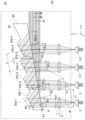
- First embodiment 1.1.1 Configuration 1 is a schematic diagram of a light source device 1 according to a first embodiment.
- the light source device 1 is used in, for example, a projector.
- the light source device 1 includes a plurality of laser light sources 2 and an optical system 3.
- Each of the multiple laser light sources 2 emits a beam B.
- the beam B is a so-called elliptical beam, in which the intensity distribution at a distance from the laser light source 2, i.e., the far-field pattern, is elliptical.
- the laser light source 2 is, for example, a semiconductor laser.
- the major axis direction, minor axis direction, and optical axis direction of each beam B are along the X direction, Y direction, and Z direction, respectively.
- the multiple laser light sources 2 are lined up in both the X direction corresponding to the major axis direction of the beam B, and the Y direction corresponding to the minor axis direction of the beam B.
- the number of laser light sources 2 is 24.
- the 24 laser light sources 2 are lined up in four rows X1 to X4 in the X direction and six rows Y1 to Y6 in the Y direction.
- the optical system 3 includes multiple collimating means 4, a prism 5, and a group of reflecting mirrors 6.
- the collimating means 4 collimates the beams B emitted from the laser light sources 2 into a plurality of substantially parallel light beams L.
- the beam width in the first direction is larger than the beam width in the second direction perpendicular to the first direction.
- the beam width of the substantially parallel light beam L in the first direction or the second direction may be defined, for example, as the distance between two points at which the radiation intensity of the substantially parallel light beam is 1/ e2 relative to the peak radiation intensity of the substantially parallel light beam.
- the beam width of the substantially parallel light beam L in the first direction or the second direction may be a full width at half maximum (FWHM).
- the first direction corresponds to the major axis direction of the beam B
- the second direction corresponds to the minor axis direction of the beam B. Since the laser light sources 2 are aligned in both the major axis direction and the minor axis direction of the beam B, the substantially parallel light beams L are aligned in both the first direction and the second direction.
- the collimating means 4 may be configured, for example, by an aspherical lens or a plurality of spherical lenses. Alternatively, they may be integrated into one to form a lens array.
- the optical system 3 has 24 collimating means 4. The 24 collimating means 4 are arranged so as to correspond one-to-one to the 24 laser light sources 2.
- Prism 5 is provided to make beam B (approximately parallel light L) perfectly circular and to improve the filling rate of beam B (approximately parallel light L).
- Prism 5 has a first surface 51 on which the multiple approximately parallel light beams L from the multiple collimating means 4 are incident, and a second surface 52 opposite to first surface 51.
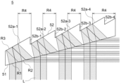
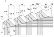
- Figure 2 is a partially enlarged view of the prism 5.
- the prism 5 has an entrance region R1 on the first surface 51 where the substantially parallel light beam L is refracted and enters the prism 5, and an exit region R2 where the substantially parallel light beam L is refracted and exits the prism 5, and a reflection region R3 on the second surface 52 where the substantially parallel light beam L that entered the prism 5 through the entrance region R1 is reflected toward the exit region R2.
- Figure 3 is a schematic front view of the light source device 1, in particular a schematic front view as seen from the -Y direction.
- Figure 4 is another schematic side view of the light source device 1, in particular a schematic side view as seen from the -X direction. Note that the group of reflective mirrors 6 is omitted in Figures 3 and 4.
- the first surface 51 is a flat surface.
- the incident region R1 and the exit region R2 are located on the same plane.
- the incident regions R1 and the exit regions R2 of the multiple substantially parallel light beams L are located on the same plane.
- the incident region R1 is a portion of the first surface 51 where the substantially parallel light beams L are incident.
- the center of the incident region R1 is a position where the central light beam L1 of the substantially parallel light beams L passes through.
- the size of the incident region R1 may be in a range where the radiation intensity of the substantially parallel light beams L is 1/e 2 of the radiation intensity of the substantially parallel light beams L at the center of the incident region R1.
- the exit region R2 is a portion of the first surface 51 where the substantially parallel light beams L are emitted.
- the center of the exit region R2 is a position where the central light beam L1 of the substantially parallel light beams L passes through.
- the size of the exit region R2 may be in a range where the radiation intensity of the substantially parallel light beams L is 1/e 2 of the radiation intensity of the substantially parallel light beams L at the center of the exit region R2.
- the first surface 51 includes an entrance region R1 and an exit region R2 corresponding to each of the multiple laser light sources 2.
- the first surface 51 includes a first entrance region R1-1 and a first exit region R2-1 corresponding to the first laser light source 2-1, and a second entrance region R1-2 and a second exit region R2-2 corresponding to the second laser light source 2-2.
- the first exit region R2-1 is between the first entrance region R1-1 and the second entrance region R1-2. This makes it possible to reduce the overlapping portion of the first surface 51 between the exit region R2 and the entrance region R1. Therefore, it is possible to reduce partial thermal expansion of the first surface 51.
- the first exit region R2-1 partially overlaps with the first entrance region R1-1, but it is more preferable that it does not overlap with either the first entrance region R1 or the second entrance region R1.
- the distance on the first surface 51 between the centers of the entrance regions R1 (first entrance region R1-1 and second entrance region R1-2) of the multiple substantially parallel light beams L that are adjacent in the first direction is defined as s [mm].
- the distance on the first surface 51 between the midpoint m between the centers of the entrance regions R1 (first entrance region R1-1 and second entrance region R1-2) and the exit region R2 (first exit region R2-1) that is closest to the midpoint m among the exit regions R2 (first exit region R2-1 and second exit region R2-2) of the adjacent substantially parallel light beams L is defined as t [mm].
- the distances s and t vary depending on the refractive index n, the angles ⁇ , ⁇ , and ⁇ , and the thickness d [mm] of the prism 5 in the direction of the optical axis of the substantially parallel light beams L that are incident on the prism 5. It is preferable that the prism 5 satisfies
- the second surface 52 When viewed from the second direction ( ⁇ Y direction) of the approximately parallel light L incident on the first surface 51, the second surface 52 is a stepped surface in which a plurality of parallel first inclined surfaces 52a and a plurality of parallel second inclined surfaces 52b are arranged alternately. Therefore, the first inclined surfaces 52a are not located on the same plane.
- the multiple first inclined surfaces 52a include a reflective region R3.
- the multiple second inclined surfaces 52b are surfaces that connect adjacent first inclined surfaces 52a.
- the second inclined surfaces 52b are not used as reflective region R3.
- the center of the reflection region R3 is a position through which the central luminous flux L1 of the approximately parallel light L passes.
- the size of the reflection region R3 may be in a range in which the radiation intensity of the approximately parallel light L is 1/ e2 of the radiation intensity of the approximately parallel light L at the center of the reflection region R3.
- the second surface 52 includes four first inclined surfaces 52a-1 to 52a-4.
- the first inclined surface 52a-1 defines the reflection region R3 of the six laser light sources 2 in row X1.
- the first inclined surfaces 52a-2 to 52a-4 correspond to rows X2 to X4.
- the reflection region R3 is located on the same plane.
- the reflection region R3 is not located on the same plane.
- the distances between the centers of the first inclined surfaces 52a and the first surface 51 are equal to each other.
- the distances between the centers of the entrance region R1 and the reflection region R3 are equal, and the distances between the centers of the exit region R3 and the reflection region R1 are equal.
- the first surface 51 is inclined with respect to a first direction ( ⁇ X direction) of the approximately parallel light L incident on the first surface 51, and the first inclined surface 52a and the second inclined surface 52b are inclined with respect to the first direction ( ⁇ X direction) of the approximately parallel light L incident on the first surface 51.
- the first surface 51 is parallel to but not inclined with respect to the second direction ( ⁇ Y direction) of the approximately parallel light L incident on the first surface 51, and the first inclined surface 52a and the second inclined surface 52b are parallel to but not inclined with respect to the second direction ( ⁇ Y direction) of the approximately parallel light L incident on the first surface 51.
- the angle of the first surface 51 with respect to the first direction is ⁇ [°]
- the angle of the first inclined surface 52a of the second surface 52 is ⁇ [°].
- the angle ⁇ is the angle of the entrance region R1 and the exit region R2, and the angle ⁇ is the angle of the reflection region R3.
- the prism 5 satisfies ⁇ > ⁇ .
- the angle ⁇ is equal to the angle of incidence of the approximately parallel light L with respect to the entrance region R1.
- the first surface 51 faces the side (right side in FIG. 3) from which the multiple nearly parallel light beams L are emitted from the prism 5 with respect to the multiple nearly parallel light beams L incident on the prism 5.
- the angles ⁇ and ⁇ are positive in the rotation direction (counterclockwise direction in FIG. 3) in which the first surface 51 approaches the second surface 52 around the rotation axis A1 along the second direction ( ⁇ Y direction in FIG. 3) on the opposite side (left side in FIG. 3) from the side (right side in FIG. 3) from which the multiple nearly parallel light beams L are emitted from the prism 5 with respect to the multiple nearly parallel light beams L incident on the prism 5.
- FIG. 3 in FIG.
- the +X direction is 0°, and the counterclockwise direction is positive.
- the rotation axis A1 is illustrated at the end of the first surface 51 on the opposite side (left side in FIG. 3) from the side (right side in FIG. 3) from which the multiple nearly parallel light beams L are emitted from the prism 5 with respect to the multiple nearly parallel light beams L incident on the prism 5.
- the rotation axis A1 is used only to determine whether the angles ⁇ and ⁇ are positive or negative, and does not necessarily refer to the rotation axis of the first surface 51 and the second surface 52.
- the angle ⁇ 0. In FIG.
- the refraction angle of the substantially parallel light L with respect to the emission region R2 is ⁇ [°]. If the refractive index of the prism 5 is n, the prism 5 satisfies the following formula (1).
- the approximately parallel light L is incident on the entrance region R1 of the first surface 51, is refracted by the entrance region R1, enters the prism 5, and travels inside the prism 5 toward the first inclined surface 52a.
- the approximately parallel light L is reflected by the reflection region R3 of the first inclined surface 52a, and travels inside the prism 5 toward the first surface 51.
- the approximately parallel light L is refracted at the exit region R2 of the first surface 51, and is emitted from the exit region R2 to the outside of the prism 5. This narrows the beam width of the approximately parallel light L in the first direction, and the spacing between the multiple approximately parallel light beams L in the first direction.
- the spacing in the first direction of the nearly parallel light L incident on the prism 5 is a1, and the beam width in the first direction is b1.
- the spacing in the third direction corresponding to the first direction in the nearly parallel light L emitted from the prism 5 is a2, and the beam width in the third direction is b2.
- the prism 5 satisfies a2 ⁇ a1 and b2 ⁇ b1.
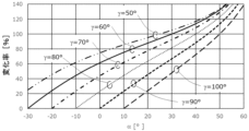
- Figure 5 is a graph showing the relationship between the angle ⁇ of the first surface 51 of the prism 5 and the rate of change of the substantially parallel light L in the first direction, as a function of the angle ⁇ .
- the rate of change of the substantially parallel light L in the first direction is expressed as a percentage of b2/b1. Therefore, a rate of change of 100% means that the beam width in the first direction does not change. A rate of change exceeding 100% means that the beam width in the first direction increases. In this case, the rate of change corresponds to the expansion rate. A rate of change of less than 100% means that the beam width in the first direction decreases. In this case, the rate of change corresponds to the reduction rate. An increase in the rate of change means an improvement in the expansion rate, and a decrease in the rate of change means an improvement in the reduction rate. A rate of change of 50% means that the beam width in the first direction is reduced by half.
- Figure 6 is a graph showing the relationship between the angle ⁇ of the first surface 51 of the prism 5 and the filling rate of the substantially parallel light L in the first direction, as a function of the angle ⁇ .
- Figure 6 shows the filling rate of the approximately parallel light L exiting the prism 5 when the filling rate of the approximately parallel light L entering the prism 5 is 50%.
- the filling rate of the approximately parallel light L exiting the prism 5 is 50%, so if the filling rate in FIG. 6 exceeds 50%, the filling rate has been improved, which means that more integration has been achieved.
- the prism 5 is set to satisfy the following equation (3).
- the filling rate of the approximately parallel light L emitted from the prism 5 is greater than the filling rate of the approximately parallel light L incident on the prism 5.
- the prism 5 satisfies the following formula (4).
- the approximately parallel light L reflected at the reflection region R3 may be totally reflected at the emission region R2 of the first surface 51. If ⁇ /2, the rate of change may be 100% or more.
- the ellipticity of a semiconductor laser (the ratio of the beam width in the minor axis direction to the beam width in the major axis direction) is approximately 0.2 to 0.5. Therefore, in order to bring the ellipticity closer to 1, it is preferable that the prism 5 satisfies the following expressions (5) and (6).
- the approximately parallel light L emitted from the emission region R2 approaches the laser light source 2, which may make it difficult to configure the optical system 3.
- the approximately parallel light L is more likely to be totally reflected in the emission region R2, and wasted space may occur in the optical system 3.
- ⁇ 1.1 ⁇ -90 the effect of compressing the beam width of the approximately parallel light L in the first direction decreases, and when ⁇ 0.95 ⁇ -60, the effect of compressing the approximately parallel light L in the first direction becomes so large that the shape of the approximately parallel light L may become elliptical, with the beam width in the first direction being smaller than the beam width in the second direction, rather than circular.
- Figure 7 is a graph showing the relationship between the angle ⁇ of the first surface 51 of the prism 5 and the rate of change of the substantially parallel light L in the first direction with respect to the refractive index n.
- Figure 8 is a graph showing the relationship between the angle ⁇ of the first surface 51 of the prism 5 and the filling rate of the substantially parallel light L in the first direction as a function of the refractive index n.
- the refractive index n is changed to 1.4, 1.5, and 1.7 when the angle ⁇ is 60° and when the angle ⁇ is 90°.
- the filling rate in Figure 8 indicates the filling rate of the approximately parallel light L emitted from the prism 5, and here, the filling rate of the approximately parallel light L incident on the prism 5 is 50%.
- Table 1 below shows an example of parameters for the light source device 1 according to this embodiment.
- the prism 5 compresses the beam width of the approximately parallel light L in the first direction.
- the beam width in the first direction is greater than the beam width in the second direction. Therefore, by compressing the beam width of the approximately parallel light L in the first direction, the approximately parallel light L changes from an elliptical shape to a shape closer to a perfect circle. Furthermore, the prism 5 makes it possible to improve the filling rate of the approximately parallel light L in the first direction.
- an anti-reflection film is formed on the first surface 51.
- the beam B is linearly polarized light. Since the first surface 51 includes the entrance region R1 and the exit region R2, it is preferable to form an anti-reflection film on the first surface 51 so as to satisfy the following formula (7), where the transmittance T ⁇ of the entrance region R1 for a predetermined linearly polarized light and the transmittance T ⁇ of the exit region R2 for a predetermined linearly polarized light.
- the beam B is S-polarized in the major axis direction and P-polarized in the minor axis direction.
- the first direction of the approximately parallel light L corresponds to the major axis direction of the beam B. Therefore, the transmittance for S-polarized light is taken into consideration in the first direction of the approximately parallel light L. That is, the predetermined linearly polarized light is S-polarized light.
- G11 and G12 correspond to the anti-reflection coating of the first example.
- G21 and G22 correspond to the anti-reflection coating of the second example.
- G11 and G21 show the change in transmittance T ⁇ of the incident region R1 for S-polarized light with respect to wavelength
- G12 and G22 show the change in transmittance T ⁇ of the exit region R2 for S-polarized light with respect to wavelength.
- the transmittance T ⁇ of the incident region R1 for S-polarized light indicates the transmittance for light incident on the first surface 51 at an angle ⁇ .
- the transmittance T ⁇ of the exit region R2 for S-polarized light indicates the transmittance for light incident on the first surface 51 at an angle equal to the refraction angle ⁇ .
- the reference wavelength of the prism 5 and the anti-reflection films of the first and second examples is 450 nm.
- the material of the prism 5 is glass, and the refractive index for the reference wavelength is 1.52532.
- the anti-reflection film of the first example is a conventionally known single-layer MgF2 film having a thickness of 1/4 of the reference wavelength.
- the anti-reflection film of the second example is a multi-layer film in which layers made of materials with different refractive indices for the reference wavelength are alternately stacked. Table 2 below shows the configuration of the anti-reflection film of the second example.
- the transmittance T ⁇ for S-polarized light in the incident region R1 is 98% or more over a wide wavelength range, but the transmittance T ⁇ for S-polarized light in the exit region R2 is 12% or less over a wide wavelength range. This shows that the transmittance is low in the single-layer coating that has been commonly used in the past. Therefore, it is desirable to improve the transmittance.
- both the transmittances T ⁇ and T ⁇ are high near the reference wavelength, and in the range from W11 to W12, T ⁇ ⁇ T ⁇ ⁇ 90%.
- W11 is 437 nm
- the approximately parallel light L can be changed from an elliptical shape to a shape closer to a perfect circle, the spacing of the approximately parallel light L in the first direction can be narrowed, and the filling rate of the approximately parallel light L can be improved. This allows the optical system 3 to be made more compact.
- the reflecting mirror group 6 is provided to improve the filling rate of the substantially parallel light L.
- the reflecting mirror group 6 includes a plurality of reflecting mirrors 6a-1 to 6a-6 that reflect the plurality of substantially parallel light L emitted from the prism 5.
- the reflecting mirrors 6a-1 to 6a-6 are arranged such that the spacing in the second direction of the plurality of substantially parallel light L after being reflected by the reflecting mirror group 6 is smaller than the spacing in the second direction of the plurality of substantially parallel light L before being reflected by the reflecting mirror group 6.
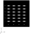
- FIG. 10 is an image showing the shape of the approximately parallel light L entering the prism 5 from the collimating means 4.
- FIG. 11 is an image showing the shape of the approximately parallel light L emitted from the prism 5.
- FIG. 12 is an image showing the shape of the approximately parallel light L reflected by the group of reflecting mirrors 6.
- whiter colors indicate higher radiation intensity.
- X1 to X4 and Y1 to Y6 in FIGS. 10 to 12 correspond to X1 to X4 and Y1 to Y6 in FIG. 1.
- the beam width in the first direction (the ⁇ X direction in FIG. 10) is larger than the beam width in the second direction (the ⁇ Y direction in FIG. 10), and the approximately parallel light L has an elliptical shape.
- the beam width in the first direction (the ⁇ Z direction in FIG. 11) is as small as the beam width in the second direction (the ⁇ Y direction in FIG. 11), and the approximately parallel light L is closer to a perfect circle than an ellipse. Furthermore, the spacing of the approximately parallel light L in the first direction is narrower.
- the spacing of the approximately parallel light L is narrowed in both the first and second directions, and the shape of the approximately parallel light L is closer to a perfect circle than an ellipse, resulting in improved beam integration.
- the prism 5 described above has a first surface 51 on which the multiple approximately parallel light beams L are incident from the multiple collimating means 4 that convert the multiple beams B emitted from the multiple laser light sources 2 into multiple approximately parallel light beams L, and a second surface 52 facing the first surface 51.
- the beam width in the first direction is larger than the beam width in the second direction perpendicular to the first direction.
- the multiple approximately parallel light beams L incident on the prism 5 are aligned at least in the first direction.
- the first surface 51 includes an entrance region R1 where the approximately parallel light beams L are refracted and enter the prism 5, and an exit region R2 where the approximately parallel light beams L are refracted and exit from the prism 5, and the second surface 52 includes a reflection region R3 that reflects the approximately parallel light beams L that have entered the prism 5 through the entrance region R1 toward the exit region R2.
- prism 5 if the spacing in a first direction of the multiple nearly parallel light beams L incident on prism 5 is a1, the beam width in the first direction is b1, and the spacing in a third direction corresponding to the first direction of the multiple nearly parallel light beams L emitted from prism 5 is a2, and the beam width in the third direction is b2, then b2/a2>b1/a1 is satisfied.
- This configuration not only compresses the beam spacing in the first direction, but also improves the beam filling rate.
- the entrance region R1 and the exit region R2 are located on the same plane in the first direction. This configuration allows the structure of the prism 5 to be simplified.
- the reflective regions R2 are arranged so as not to be located on the same plane in the first direction. This configuration allows the prism 5 to be made thinner.
- the distance between the center of the incident region R1 and the center of the reflective region R3 is equal, and the distance between the center of the exit region R2 and the center of the reflective region R3 is equal. This configuration allows the prism 5 to be made thinner.
- Prism 5 further satisfies 50 ⁇ 100 and 1.1 ⁇ -90 ⁇ 0.95 ⁇ -60. This configuration allows for further improvement in the reduction ratio and filling rate of the substantially parallel light L in the first direction.
- the light source device 1 described above includes a plurality of laser light sources 2, a plurality of collimating means 4 for converting a plurality of beams B emitted from the plurality of laser light sources 2 into a plurality of approximately parallel light beams L, and a prism 5 having a first surface 51 on which the plurality of approximately parallel light beams L are incident from the plurality of collimating means 4 and a second surface 52 facing the first surface 51.
- the beam width in the first direction is greater than the beam width in the second direction perpendicular to the first direction.
- the plurality of approximately parallel light beams L are aligned at least in the first direction.
- the first surface 51 includes an entrance region R1 where the approximately parallel light beam L is refracted and enters the prism 5, and an exit region R2 where the approximately parallel light beam L is refracted and exits the prism 5, and the second surface 52 includes a reflection region R3 that reflects the approximately parallel light beam L that entered the prism 5 through the entrance region R1 toward the exit region R2.
- the multiple substantially parallel light beams L that enter the prism 5 are aligned in both the first and second directions. This configuration allows for high output because the laser light source 2 is arranged on a flat surface.
- the light source device 1 further includes a reflecting mirror group 6 that reflects the multiple approximately parallel light beams L emitted from the prism 5.
- the reflecting mirror group 6 includes multiple reflecting mirrors 6a that are arranged such that the spacing in the second direction of the multiple approximately parallel light beams L after being reflected by the reflecting mirror group 6 is smaller than the spacing in the second direction of the multiple approximately parallel light beams L before being reflected by the reflecting mirror group 6. This configuration can also compress the spacing of the beams in the second direction.
- Second embodiment 1.2.1 Configuration 13 is a schematic side view of a light source device 1A according to the second embodiment, particularly a schematic side view seen from the -Y direction.
- the light source device 1A includes a plurality of laser light sources 2 and an optical system 3A.
- the optical system 3A includes a plurality of collimating means 4 and a prism 5A.
- prism 5A has a first surface 51 and a second surface 52, but differs from prism 5 mainly in the refractive index n, angle ⁇ , angle ⁇ , angle ⁇ , and thickness d.
- Table 3 below shows an example of parameters for the light source device 1A in this embodiment.
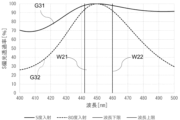
- the 14 is a graph showing the transmittance of the first surface 51 of the prism 5A for S-polarized light.
- G31 shows the change in transmittance T ⁇ with respect to wavelength
- G32 shows the change in transmittance T ⁇ with respect to wavelength.
- the reference wavelength of prism 5A and the anti-reflection coating is 450 nm.
- Prism 5A is made of glass, and has a refractive index of 1.4391 for the reference wavelength.
- the anti-reflection coating of prism 5A is a multi-layer coating in which layers made of materials with different refractive indices for the reference wavelength are alternately stacked.
- the composition of the anti-reflection coating is shown in Table 4 below.
- the prism 5A makes it possible to adjust the beam spacing, shape, and filling rate.
- the approximately parallel light L can be changed from an elliptical shape to one closer to a perfect circle, narrowing the spacing of the approximately parallel light L in the first direction and improving the filling rate of the approximately parallel light L. This allows the optical system to be made more compact.
- the prism 5A described above satisfies ⁇ > ⁇ .
- This configuration can narrow the interval between the beams (approximately parallel light L) with a simple structure, and further enables the beams (approximately parallel light L) to be made perfectly circular and the filling rate to be improved.
- Prism 5A satisfies b2/a2>b1/a1. This configuration not only compresses the beam spacing in the first direction, but also improves the beam filling rate.
- This configuration can achieve high transmittance even when there are two refractions at different angles in the entrance region R1 and the exit region R2.
- Prism 5A satisfies ⁇ -90 ⁇ /2. This configuration enables an improvement in the reduction ratio and filling rate of the substantially parallel light L in the first direction.
- Prism 5A further satisfies 50 ⁇ 100 and 1.1 ⁇ -90 ⁇ 0.95 ⁇ -60. This configuration allows for further improvement in the reduction ratio and filling rate of the substantially parallel light L in the first direction.
- Third embodiment 1.3.1 Configuration 15 is a schematic side view of a light source device 1B according to the third embodiment, particularly a schematic side view seen from the -Y direction.
- the light source device 1B includes a plurality of laser light sources 2 and an optical system 3B.
- the optical system 3B includes a plurality of collimating means 4 and a prism 5B.
- prism 5B has a first surface 51 and a second surface 52, but differs from prism 5 mainly in the refractive index n, angle ⁇ , angle ⁇ , angle ⁇ , and thickness d.
- Table 5 below shows an example of parameters for the light source device 1B in this embodiment.
- FIG 16 is a graph showing the transmittance of the first surface 51 of the prism 5B for S-polarized light.
- G41 shows the change in transmittance T ⁇ with respect to wavelength
- G42 shows the change in transmittance T ⁇ with respect to wavelength.
- the reference wavelength of prism 5B and the anti-reflection coating is 500 nm.
- Prism 5B is made of glass, and has a refractive index of 1.62904 for the reference wavelength.
- the anti-reflection coating of prism 5B is a multi-layer coating in which layers made of materials with different refractive indices for the reference wavelength are alternately stacked.
- the composition of the anti-reflection coating is shown in Table 6 below.
- T ⁇ ⁇ T ⁇ ⁇ 90% is obtained in the wavelength range of W31 to W32 including the reference wavelength.
- W31 is 487 nm
- the antireflection film having the configuration of Table 6 can be a simple two-layer structure.
- the prism 5B makes it possible to adjust the beam spacing, shape, and filling rate.
- the approximately parallel light L can be changed from an elliptical shape to one closer to a perfect circle, narrowing the spacing of the approximately parallel light L in the first direction and improving the filling rate of the approximately parallel light L. This allows the optical system to be made more compact.
- the prism 5B described above satisfies ⁇ > ⁇ .
- This configuration can narrow the interval between the beams (approximately parallel light L) with a simple structure, and further enables the beams (approximately parallel light L) to be made perfectly circular and the filling rate to be improved.
- Prism 5B satisfies b2/a2>b1/a1. This configuration not only compresses the beam spacing in the first direction, but also improves the beam filling rate.
- This configuration can achieve high transmittance even when refraction occurs twice at different angles in the entrance region R1 and the exit region R2.
- Prism 5B satisfies ⁇ -90 ⁇ /2. This configuration enables an improvement in the reduction ratio and filling rate of the substantially parallel light L in the first direction.
- Prism 5B further satisfies 50 ⁇ 100 and 1.1 ⁇ -90 ⁇ 0.95 ⁇ -60. This configuration allows for further improvement in the reduction ratio and filling rate of the substantially parallel light L in the first direction.
- Configuration 17 is a schematic side view of a light source device 1C according to the fourth embodiment, particularly a schematic side view seen from the -Y direction.
- the light source device 1C includes a plurality of laser light sources 2 and an optical system 3C.
- the optical system 3C includes a plurality of collimating means 4 and a prism 5C.
- prism 5B has a first surface 51 and a second surface 52, but differs from prism 5 mainly in the refractive index n, angle ⁇ , angle ⁇ , angle ⁇ , and thickness d.
- the first surface 51 faces the opposite side to the side from which the multiple approximately parallel light beams L exit the prism 5 (right side in FIG. 17) with respect to the multiple approximately parallel light beams L entering the prism 5.
- the angles ⁇ and ⁇ are positive in the rotation direction (clockwise direction in FIG. 17) in which the first surface 51 moves away from the second surface 52 around the rotation axis A1 along the second direction ( ⁇ Y direction in FIG. 17) on the opposite side (left side in FIG. 17) from the side from which the multiple approximately parallel light beams L exit the prism 5 with respect to the multiple approximately parallel light beams L entering the prism 5 (right side in FIG. 17).
- the -X direction is 0°, and the clockwise direction is positive.
- the rotation axis A1 is illustrated at the end of the first surface 51 on the opposite side (left side in FIG. 17) from the side from which the multiple approximately parallel light beams L exit the prism 5 with respect to the multiple approximately parallel light beams L entering the prism 5 (right side in FIG. 17).
- Table 7 below shows an example of parameters for the light source device 1C in this embodiment.
- the approximately parallel light beams L can pass through the incident region R1 and enter the prism 5C. From a comparison of Tables 1 and 7, it can be seen that the filling rate is very high when the first surface 51 faces the opposite side of the multiple approximately parallel light beams L incident on the prism 5, rather than the side where the multiple approximately parallel light beams L exit the prism 5.
- the filling rate of the approximately parallel light beams L incident on the prism 5C is 50.0%, whereas the filling rate of the approximately parallel light beams L exiting the prism 5C is very high at 84.1%, so that the prism 5C can greatly improve the integration of the beam and can focus the beam in a narrower range.
- the angle ⁇ is -20.000 and the angle ⁇ is 6.604, and in this case too, ⁇ > ⁇ is satisfied. From this point of view, the angle ⁇ being negative can be said to mean that the first surface 51 faces the side opposite to the side from which the multiple approximately parallel light beams L exit the prism 5 with respect to the multiple approximately parallel light beams L entering the prism 5.
- the prism 5C makes it possible to adjust the beam spacing, shape, and filling rate.
- the approximately parallel light L can be changed from an elliptical shape to one closer to a perfect circle, narrowing the spacing of the approximately parallel light L in the first direction and improving the filling rate of the approximately parallel light L. This allows the optical system to be made more compact.
- the prism 5C described above satisfies ⁇ > ⁇ .
- This configuration can narrow the interval between the beams (approximately parallel light L) with a simple structure, and further enables the beams (approximately parallel light L) to be made perfectly circular and the filling rate to be improved.
- Prism 5C satisfies b2/a2>b1/a1. This configuration not only reduces the beam spacing in the first direction, but also improves the beam filling rate.
- This configuration can achieve high transmittance even when refraction occurs twice at different angles in the entrance region R1 and the exit region R2.
- Prism 5C satisfies ⁇ -90 ⁇ /2. This configuration enables an improvement in the reduction ratio and filling rate of the substantially parallel light L in the first direction.
- Prism 5C further satisfies 50 ⁇ 100 and 1.1 ⁇ -90 ⁇ 0.95 ⁇ -60. This configuration allows for further improvement in the reduction ratio and filling rate of the substantially parallel light L in the first direction.
- the light source device 1D includes a plurality of laser light sources 2 and an optical system 3D.
- the optical system 3D includes a plurality of collimating means 4 and a prism 5D.
- prism 5D has a first surface 51 and a second surface 52, but differs from prism 5 mainly in the refractive index n, angle ⁇ , angle ⁇ , angle ⁇ , and thickness d.
- Table 8 below shows an example of parameters for the light source device 1D in this embodiment.
- Prism 5D compresses the beam width of the approximately parallel light L in the first direction.
- the beam width in the first direction is greater than the beam width in the second direction. Therefore, by compressing the beam width of the approximately parallel light L in the first direction, the approximately parallel light L changes from an elliptical shape to one closer to a perfect circle.
- prism 5D makes it possible to improve the filling rate of the approximately parallel light L in the first direction.
- an anti-reflection film is formed on the first surface 51.
- the beam B is linearly polarized. If the transmittance T ⁇ of the incident region R1 for a predetermined linearly polarized light and the transmittance T ⁇ of the exit region R2 for a predetermined linearly polarized light, it is preferable that an anti-reflection film is formed on the first surface 51 so as to satisfy the above formula (7).
- the beam B is P-polarized in the major axis direction and S-polarized in the minor axis direction.
- the first direction of the approximately parallel light L corresponds to the major axis direction of the beam B. Therefore, in the first direction of the approximately parallel light L, the transmittance for P-polarized light is taken into consideration. That is, the predetermined linearly polarized light is P-polarized light.
- FIG 19 is a graph showing the transmittance of the first surface 51 of the prism 5D for P-polarized light.
- G51 shows the change in transmittance T ⁇ with respect to wavelength
- G52 shows the change in transmittance T ⁇ with respect to wavelength.
- the reference wavelength of prism 5D and the anti-reflection coating is 635 nm.
- Prism 5D is made of glass, and has a refractive index of 1.456954 for the reference wavelength.
- the anti-reflection coating of prism 5D is a multi-layer coating in which layers made of materials with different refractive indices for the reference wavelength are alternately stacked. Table 9 below shows the composition of the anti-reflection coating.
- W41 is 629 nm
- the prism 5D makes it possible to adjust the beam spacing, shape, and filling rate.
- a single prism 5D can change the shape of the approximately parallel light L from an elliptical shape to something closer to a perfect circle, narrowing the spacing of the approximately parallel light L in the first direction and improving the filling rate of the approximately parallel light L. This allows the optical system to be made more compact.
- the prism 5D described above satisfies ⁇ > ⁇ .
- This configuration can narrow the interval between the beams (approximately parallel light L) with a simple structure, and further enables the beams (approximately parallel light L) to be made perfectly circular and the filling rate to be improved.
- Prism 5D satisfies b2/a2>b1/a1. This configuration not only reduces the beam spacing in the first direction, but also improves the beam filling rate.
- Prism 5D satisfies ⁇ -90 ⁇ /2. This configuration enables an improvement in the reduction ratio and filling rate of the substantially parallel light L in the first direction.
- Prism 5D further satisfies 50 ⁇ 100 and 1.1 ⁇ -90 ⁇ 0.95 ⁇ -60. This configuration allows for further improvement in the reduction ratio and filling rate of the substantially parallel light L in the first direction.
- Sixth embodiment 1.6.1 Configuration 20 is a schematic side view of a light source device 1E according to the sixth embodiment, particularly a schematic side view seen from the -Y direction.
- the light source device 1E includes a plurality of laser light sources 2 and an optical system 3E.
- the optical system 3E includes a plurality of collimating means 4 and a prism 5E.
- prism 5E has a first surface 51 and a second surface 52, but differs from prism 5 mainly in the refractive index n, angle ⁇ , angle ⁇ , angle ⁇ , and thickness d.
- Table 10 below shows an example of parameters for the light source device 1E according to this embodiment.
- the rate of change of the approximately parallel light L in the first direction is 222%, which exceeds 100%. Therefore, prism 5E expands the beam width of the approximately parallel light L in the first direction. In the approximately parallel light L, the beam width in the first direction is smaller than the beam width in the second direction. Therefore, by expanding the beam width of the approximately parallel light L in the first direction, the approximately parallel light L changes from an elliptical shape to one closer to a perfect circle. In addition, prism 5E makes it possible to reduce the filling rate of the approximately parallel light L in the first direction.
- the 21 is a graph showing the transmittance of the first surface 51 of the prism 5E for S-polarized light.
- G61 shows the change in transmittance T ⁇ with respect to wavelength
- G62 shows the change in transmittance T ⁇ with respect to wavelength.
- the reference wavelength of prism 5E and the anti-reflection coating is 455 nm.
- Prism 5E is made of glass, and has a refractive index of 1.524396 for the reference wavelength.
- the anti-reflection coating of prism 5E is a multi-layer coating in which layers made of materials with different refractive indices for the reference wavelength are alternately stacked.
- the composition of the anti-reflection coating is shown in Table 11 below.
- W51 is 424 nm
- the prism 5E makes it possible to adjust the beam spacing, shape, and filling rate.
- the approximately parallel light L can be changed from an elliptical shape to something closer to a perfect circle, the spacing of the approximately parallel light L in the first direction can be increased, and the filling rate of the approximately parallel light L can be reduced.
- the prism 5E can increase the distance between the beams B while correcting the shape of the beams B, making it easier to configure the optical system.
- Figure 22 is a partial front view of the prism 5 according to the first embodiment.
- the approximately parallel light L is refracted at the entrance region R1 of the first surface 51 and enters the prism 5, reflected at the reflection region R3 of the second surface 52 within the prism 5, refracted at the exit region R2 of the first surface 51 and emitted outside the prism 5.
- the prism 5 there are portions that have very little effect on the refraction and reflection of the multiple approximately parallel light beams L.
- portions of the second surface 52 other than the reflection region R3, mainly the second inclined surface 52b and the boundary between the second inclined surface 52b and the first inclined surface 52a have very little effect on the reflection of the approximately parallel light L.
- the peripheral edge of the approximately parallel light L may be present on the second inclined surface 52b and on the boundary between the second inclined surface 52b and the first inclined surface 52a, but the peripheral edge of the approximately parallel light L is a portion where the radiation intensity of the semiconductor laser, which usually has a Gaussian distribution, is almost zero. Therefore, the portion other than the reflection region R3, such as the second inclined surface 52b and the boundary between the second inclined surface 52b and the first inclined surface 52a, is an ineffective portion R4 that has very little effect on the light utilization efficiency. Therefore, the shape of such an ineffective portion R4 may be any shape.
- FIG. 23 is a partial front view of a prism 5 according to a modified example.
- the second inclined surface 52b of the second surface 52 is a surface along the ⁇ Z direction.
- FIG. 24 is a partial front view of a prism 5 according to another modified example.
- the ridgeline between the first inclined surface 52a and the second inclined surface 52b of the second surface 52 is rounded.
- the prism 5 can be manufactured by polishing, glass molding, resin molding, or the like.
- the shape of FIG. 22 or FIG. 240 has a smaller aspect ratio than the shape of FIG. 23, so deformation of the shape during molding is more easily suppressed and the mold can be easily removed, which is preferable.
- the ineffective portion R4 of the prism 5 is not limited to the shapes shown in Figures 22 to 24, and may be set to a shape suitable for the manufacturing method of the prism 5 using the degree of freedom of the ineffective portion R4.
- the multiple laser light sources 2 may be structured such that each is mounted in a can package, or may be structured as an integrated structure.
- the multiple collimating means 4 may be integrated into one optical component.
- the multiple collimating means 4 may be provided as a light source unit together with the multiple laser light sources 2.
- the optical system 3 does not need to include multiple collimating means 4.
- the first surface 51 may not be a flat surface, but may be a stepped surface like the second surface 52.
- the entrance region R1 and the exit region R2 do not have to be located on the same plane in the first direction.
- the entrance region R1 or the exit region R2 may be arranged so as not to be located on the same plane in the first direction. Note that when the first surface 51 is a stepped surface like the second surface 52, the second surface 52 may be a flat surface.
- a reflective film may be formed on the second surface 52 of the prism 5, particularly on the first inclined surface 52a.
- the reflective film may be a dielectric multilayer film or a metal coating film, as long as it has a high reflectance in a desired wavelength range that includes the wavelength of the substantially parallel light L.
- the optical system 3 may not include the reflective mirror group 6.
- the optical systems 3A, 3B, 3C, 3D, and 3E may include the reflective mirror group 6.
- the first surface includes an entrance area where the substantially parallel light is refracted to enter the prism and an exit area where the substantially parallel light is refracted to exit the prism
- the second surface includes a reflection region that reflects the substantially parallel light that has passed through the entrance region and entered the prism toward the exit region, prism.
- the reflective areas are arranged so as not to be coplanar in the first direction.
- the prism according to any one of embodiments 1 to 7.
- the reflection mirror group includes a plurality of reflection mirrors arranged such that an interval in the second direction of the plurality of substantially parallel beams after being reflected by the reflection mirror group is smaller than an interval in the second direction of the plurality of substantially parallel beams before being reflected by the reflection mirror group,
- Aspects 2 to 13, 15, and 16 are optional elements and are not required. Aspects 2 to 13 can be appropriately combined with aspects 14 to 16.
- This disclosure is applicable to prisms and light source devices. Specifically, this disclosure is applicable to a prism for integrating beams from multiple laser light sources, and a light source device including such a prism.
Landscapes
- Physics & Mathematics (AREA)
- General Physics & Mathematics (AREA)
- Optics & Photonics (AREA)
- Condensed Matter Physics & Semiconductors (AREA)
- Electromagnetism (AREA)
- Engineering & Computer Science (AREA)
- General Engineering & Computer Science (AREA)
- Optical Elements Other Than Lenses (AREA)
Priority Applications (2)
| Application Number | Priority Date | Filing Date | Title |
|---|---|---|---|
| JP2025516705A JPWO2024225039A1 (https=) | 2023-04-28 | 2024-04-10 | |
| CN202480027819.9A CN121002406A (zh) | 2023-04-28 | 2024-04-10 | 棱镜、光源装置 |
Applications Claiming Priority (2)
| Application Number | Priority Date | Filing Date | Title |
|---|---|---|---|
| JP2023075204 | 2023-04-28 | ||
| JP2023-075204 | 2023-04-28 |
Publications (1)
| Publication Number | Publication Date |
|---|---|
| WO2024225039A1 true WO2024225039A1 (ja) | 2024-10-31 |
Family
ID=93256393
Family Applications (1)
| Application Number | Title | Priority Date | Filing Date |
|---|---|---|---|
| PCT/JP2024/014553 Ceased WO2024225039A1 (ja) | 2023-04-28 | 2024-04-10 | プリズム、光源装置 |
Country Status (3)
| Country | Link |
|---|---|
| JP (1) | JPWO2024225039A1 (https=) |
| CN (1) | CN121002406A (https=) |
| WO (1) | WO2024225039A1 (https=) |
Citations (6)
| Publication number | Priority date | Publication date | Assignee | Title |
|---|---|---|---|---|
| JP2001338433A (ja) * | 2000-05-24 | 2001-12-07 | Hitachi Ltd | 光ヘッド及びそれを用いた光ディスク装置 |
| JP2002207110A (ja) * | 2001-01-10 | 2002-07-26 | Ricoh Co Ltd | 複合機能プリズム及び光ピックアップ装置 |
| JP2005114977A (ja) * | 2003-10-07 | 2005-04-28 | Ricoh Opt Ind Co Ltd | 光パワー合成用光学系および光源モジュール |
| JP2012525604A (ja) * | 2009-04-30 | 2012-10-22 | イーストマン コダック カンパニー | 配列された光源を使用するデジタルプロジェクタ |
| JP2014203500A (ja) * | 2013-04-10 | 2014-10-27 | 株式会社日立メディアエレクトロニクス | 光情報記録再生装置 |
| WO2016157754A1 (ja) * | 2015-03-27 | 2016-10-06 | セイコーエプソン株式会社 | 光源装置、照明装置、およびプロジェクター |
-
2024
- 2024-04-10 CN CN202480027819.9A patent/CN121002406A/zh active Pending
- 2024-04-10 WO PCT/JP2024/014553 patent/WO2024225039A1/ja not_active Ceased
- 2024-04-10 JP JP2025516705A patent/JPWO2024225039A1/ja active Pending
Patent Citations (6)
| Publication number | Priority date | Publication date | Assignee | Title |
|---|---|---|---|---|
| JP2001338433A (ja) * | 2000-05-24 | 2001-12-07 | Hitachi Ltd | 光ヘッド及びそれを用いた光ディスク装置 |
| JP2002207110A (ja) * | 2001-01-10 | 2002-07-26 | Ricoh Co Ltd | 複合機能プリズム及び光ピックアップ装置 |
| JP2005114977A (ja) * | 2003-10-07 | 2005-04-28 | Ricoh Opt Ind Co Ltd | 光パワー合成用光学系および光源モジュール |
| JP2012525604A (ja) * | 2009-04-30 | 2012-10-22 | イーストマン コダック カンパニー | 配列された光源を使用するデジタルプロジェクタ |
| JP2014203500A (ja) * | 2013-04-10 | 2014-10-27 | 株式会社日立メディアエレクトロニクス | 光情報記録再生装置 |
| WO2016157754A1 (ja) * | 2015-03-27 | 2016-10-06 | セイコーエプソン株式会社 | 光源装置、照明装置、およびプロジェクター |
Also Published As
| Publication number | Publication date |
|---|---|
| JPWO2024225039A1 (https=) | 2024-10-31 |
| CN121002406A (zh) | 2025-11-21 |
Similar Documents
| Publication | Publication Date | Title |
|---|---|---|
| JP7125640B2 (ja) | 透過型回折格子の製造方法 | |
| US6310905B1 (en) | Mirror for an ultraviolet laser and method | |
| US8885254B2 (en) | Laminated diffractive optical element and optical system | |
| US4948233A (en) | Beam shaping optical system | |
| US20230108188A1 (en) | Diffractive optical element, projection device, and measurement device` | |
| CN113552726A (zh) | 激光合束装置及其组合式阶梯反射镜和填充率计算方法 | |
| CN1885094A (zh) | 全内反射式微棱镜阵列实现面阵半导体激光器光束整形的方法 | |
| US20260079411A1 (en) | Optical element for the ultraviolet wavelength range | |
| WO2024225039A1 (ja) | プリズム、光源装置 | |
| US6703634B2 (en) | 3D-shape measurement apparatus | |
| CN219676386U (zh) | 一种光束分束平行输出装置 | |
| JPH05303049A (ja) | シェーディングを軽減した光走査装置 | |
| JP7400632B2 (ja) | 照明装置およびプロジェクター | |
| KR20170074868A (ko) | 투영 노광 시스템용 조명 광학 유닛 | |
| US11503257B2 (en) | Light source device and projection image display device | |
| US20230021930A1 (en) | Meta-optical device for collimating and deflecting light beam | |
| US10971882B2 (en) | Light source module | |
| CN221946336U (zh) | 一种光学系统 | |
| US12276814B2 (en) | Laser beam combining apparatus, and combined stepped reflector and filling rate calculation method thereof | |
| CN112698542B (zh) | 一种激光光源 | |
| US12339573B2 (en) | Light source device and projector | |
| KR102167221B1 (ko) | 비대칭 투과필름 | |
| CN116300282B (zh) | 一种投影设备及投影系统 | |
| WO2025109861A1 (ja) | 投写光学系および画像投写装置 | |
| CN120184726A (zh) | 激光压缩系统及激光加工装置 |
Legal Events
| Date | Code | Title | Description |
|---|---|---|---|
| 121 | Ep: the epo has been informed by wipo that ep was designated in this application |
Ref document number: 24796795 Country of ref document: EP Kind code of ref document: A1 |
|
| ENP | Entry into the national phase |
Ref document number: 2025516705 Country of ref document: JP Kind code of ref document: A |
|
| WWE | Wipo information: entry into national phase |
Ref document number: 2025516705 Country of ref document: JP |
|
| NENP | Non-entry into the national phase |
Ref country code: DE |