WO2024224687A1 - コード-ゴム複合体、コード-ゴム複合体の製造方法、タイヤ - Google Patents
コード-ゴム複合体、コード-ゴム複合体の製造方法、タイヤ Download PDFInfo
- Publication number
- WO2024224687A1 WO2024224687A1 PCT/JP2023/045812 JP2023045812W WO2024224687A1 WO 2024224687 A1 WO2024224687 A1 WO 2024224687A1 JP 2023045812 W JP2023045812 W JP 2023045812W WO 2024224687 A1 WO2024224687 A1 WO 2024224687A1
- Authority
- WO
- WIPO (PCT)
- Prior art keywords
- cord
- belt layer
- rubber
- steel
- steel cord
- Prior art date
- Legal status (The legal status is an assumption and is not a legal conclusion. Google has not performed a legal analysis and makes no representation as to the accuracy of the status listed.)
- Ceased
Links
Images






Classifications
-
- B—PERFORMING OPERATIONS; TRANSPORTING
- B60—VEHICLES IN GENERAL
- B60C—VEHICLE TYRES; TYRE INFLATION; TYRE CHANGING; CONNECTING VALVES TO INFLATABLE ELASTIC BODIES IN GENERAL; DEVICES OR ARRANGEMENTS RELATED TO TYRES
- B60C9/00—Reinforcements or ply arrangement of pneumatic tyres
- B60C9/0007—Reinforcements made of metallic elements, e.g. cords, yarns, filaments or fibres made from metal
-
- B—PERFORMING OPERATIONS; TRANSPORTING
- B60—VEHICLES IN GENERAL
- B60C—VEHICLE TYRES; TYRE INFLATION; TYRE CHANGING; CONNECTING VALVES TO INFLATABLE ELASTIC BODIES IN GENERAL; DEVICES OR ARRANGEMENTS RELATED TO TYRES
- B60C9/00—Reinforcements or ply arrangement of pneumatic tyres
-
- B—PERFORMING OPERATIONS; TRANSPORTING
- B60—VEHICLES IN GENERAL
- B60C—VEHICLE TYRES; TYRE INFLATION; TYRE CHANGING; CONNECTING VALVES TO INFLATABLE ELASTIC BODIES IN GENERAL; DEVICES OR ARRANGEMENTS RELATED TO TYRES
- B60C9/00—Reinforcements or ply arrangement of pneumatic tyres
- B60C9/18—Structure or arrangement of belts or breakers, crown-reinforcing or cushioning layers
- B60C9/20—Structure or arrangement of belts or breakers, crown-reinforcing or cushioning layers built-up from rubberised plies each having all cords arranged substantially parallel
- B60C9/2003—Structure or arrangement of belts or breakers, crown-reinforcing or cushioning layers built-up from rubberised plies each having all cords arranged substantially parallel characterised by the materials of the belt cords
- B60C9/2006—Structure or arrangement of belts or breakers, crown-reinforcing or cushioning layers built-up from rubberised plies each having all cords arranged substantially parallel characterised by the materials of the belt cords consisting of steel cord plies only
-
- B—PERFORMING OPERATIONS; TRANSPORTING
- B60—VEHICLES IN GENERAL
- B60C—VEHICLE TYRES; TYRE INFLATION; TYRE CHANGING; CONNECTING VALVES TO INFLATABLE ELASTIC BODIES IN GENERAL; DEVICES OR ARRANGEMENTS RELATED TO TYRES
- B60C9/00—Reinforcements or ply arrangement of pneumatic tyres
- B60C9/18—Structure or arrangement of belts or breakers, crown-reinforcing or cushioning layers
- B60C9/20—Structure or arrangement of belts or breakers, crown-reinforcing or cushioning layers built-up from rubberised plies each having all cords arranged substantially parallel
- B60C9/2003—Structure or arrangement of belts or breakers, crown-reinforcing or cushioning layers built-up from rubberised plies each having all cords arranged substantially parallel characterised by the materials of the belt cords
- B60C9/2009—Structure or arrangement of belts or breakers, crown-reinforcing or cushioning layers built-up from rubberised plies each having all cords arranged substantially parallel characterised by the materials of the belt cords comprising plies of different materials
-
- D—TEXTILES; PAPER
- D07—ROPES; CABLES OTHER THAN ELECTRIC
- D07B—ROPES OR CABLES IN GENERAL
- D07B1/00—Constructional features of ropes or cables
- D07B1/06—Ropes or cables built-up from metal wires, e.g. of section wires around a hemp core
-
- B—PERFORMING OPERATIONS; TRANSPORTING
- B60—VEHICLES IN GENERAL
- B60C—VEHICLE TYRES; TYRE INFLATION; TYRE CHANGING; CONNECTING VALVES TO INFLATABLE ELASTIC BODIES IN GENERAL; DEVICES OR ARRANGEMENTS RELATED TO TYRES
- B60C9/00—Reinforcements or ply arrangement of pneumatic tyres
- B60C9/0007—Reinforcements made of metallic elements, e.g. cords, yarns, filaments or fibres made from metal
- B60C2009/0014—Surface treatments of steel cords
-
- B—PERFORMING OPERATIONS; TRANSPORTING
- B60—VEHICLES IN GENERAL
- B60C—VEHICLE TYRES; TYRE INFLATION; TYRE CHANGING; CONNECTING VALVES TO INFLATABLE ELASTIC BODIES IN GENERAL; DEVICES OR ARRANGEMENTS RELATED TO TYRES
- B60C9/00—Reinforcements or ply arrangement of pneumatic tyres
- B60C9/0007—Reinforcements made of metallic elements, e.g. cords, yarns, filaments or fibres made from metal
- B60C2009/0021—Coating rubbers for steel cords
-
- B—PERFORMING OPERATIONS; TRANSPORTING
- B60—VEHICLES IN GENERAL
- B60C—VEHICLE TYRES; TYRE INFLATION; TYRE CHANGING; CONNECTING VALVES TO INFLATABLE ELASTIC BODIES IN GENERAL; DEVICES OR ARRANGEMENTS RELATED TO TYRES
- B60C9/00—Reinforcements or ply arrangement of pneumatic tyres
- B60C2009/0071—Reinforcements or ply arrangement of pneumatic tyres characterised by special physical properties of the reinforcements
- B60C2009/0092—Twist structure
-
- B—PERFORMING OPERATIONS; TRANSPORTING
- B60—VEHICLES IN GENERAL
- B60C—VEHICLE TYRES; TYRE INFLATION; TYRE CHANGING; CONNECTING VALVES TO INFLATABLE ELASTIC BODIES IN GENERAL; DEVICES OR ARRANGEMENTS RELATED TO TYRES
- B60C9/00—Reinforcements or ply arrangement of pneumatic tyres
- B60C9/18—Structure or arrangement of belts or breakers, crown-reinforcing or cushioning layers
- B60C9/20—Structure or arrangement of belts or breakers, crown-reinforcing or cushioning layers built-up from rubberised plies each having all cords arranged substantially parallel
- B60C2009/2074—Physical properties or dimension of the belt cord
-
- B—PERFORMING OPERATIONS; TRANSPORTING
- B60—VEHICLES IN GENERAL
- B60C—VEHICLE TYRES; TYRE INFLATION; TYRE CHANGING; CONNECTING VALVES TO INFLATABLE ELASTIC BODIES IN GENERAL; DEVICES OR ARRANGEMENTS RELATED TO TYRES
- B60C9/00—Reinforcements or ply arrangement of pneumatic tyres
- B60C9/18—Structure or arrangement of belts or breakers, crown-reinforcing or cushioning layers
- B60C9/20—Structure or arrangement of belts or breakers, crown-reinforcing or cushioning layers built-up from rubberised plies each having all cords arranged substantially parallel
- B60C2009/2074—Physical properties or dimension of the belt cord
- B60C2009/2077—Diameters of the cords; Linear density thereof
-
- B—PERFORMING OPERATIONS; TRANSPORTING
- B60—VEHICLES IN GENERAL
- B60C—VEHICLE TYRES; TYRE INFLATION; TYRE CHANGING; CONNECTING VALVES TO INFLATABLE ELASTIC BODIES IN GENERAL; DEVICES OR ARRANGEMENTS RELATED TO TYRES
- B60C9/00—Reinforcements or ply arrangement of pneumatic tyres
- B60C9/18—Structure or arrangement of belts or breakers, crown-reinforcing or cushioning layers
- B60C9/20—Structure or arrangement of belts or breakers, crown-reinforcing or cushioning layers built-up from rubberised plies each having all cords arranged substantially parallel
- B60C2009/2074—Physical properties or dimension of the belt cord
- B60C2009/2096—Twist structures
Definitions
- This disclosure relates to cord-rubber composites, methods for manufacturing cord-rubber composites, and tires.
- Patent Document 1 discloses a pneumatic tire in which a belt layer containing a plurality of aligned single-strand steel wires is embedded on the outer circumferential side of the carcass layer in the tread portion, the single-strand steel wires having a flat cross-sectional shape, and the thickness of the rubber under the grooves in the tread portion is 1.0 mm to 2.0 mm.
- the cord-rubber composite of the present disclosure is a cord-rubber composite having a structure in which a first belt layer and a second belt layer are laminated,
- the first belt layer is disposed so as to include at least one surface of the cord-rubber composite,
- the first belt layer has a first rubber and a plurality of first steel cords embedded in the first rubber,
- the second belt layer has a second rubber and a plurality of second steel cords embedded in the second rubber, the first steel cord is a stranded wire formed by stranding a plurality of wires,
- the second steel cord is a solid wire.
- FIG. 1 is a cross-sectional view of a cord-rubber composite according to one embodiment of the present disclosure.
- FIG. 2 is a perspective view of a steel cord having a single twist structure.
- FIG. 3 is a cross-sectional view of a steel cord having a single twist structure.
- FIG. 4 is a cross-sectional view of a steel cord having a layered twist structure.
- FIG. 5 is a cross-sectional view of the second steel cord.
- FIG. 6 is an explanatory diagram of a method for measuring the coil diameter.
- FIG. 7 is an explanatory diagram of a method for producing the second steel cord.
- FIG. 8 is an explanatory diagram of a method for manufacturing a belt layer included in a cord-rubber composite according to one embodiment of the present disclosure.
- FIG. 9A is a flow diagram of a method for manufacturing a belt layer according to one aspect of the present disclosure.
- FIG. 9B is a flow diagram of a method for making a cord-rubber composite according to one aspect of the present disclosure.
- FIG. 10 is a cross-sectional view of a tire according to one aspect of the disclosure.
- FIG. 11 is an explanatory diagram of a method for evaluating the curvature.
- FIG. 12 is an explanatory diagram of a method for evaluating position accuracy.
- FIG. 13 is an explanatory diagram of a method for evaluating the irregularity followability.
- the present disclosure aims to provide a cord-rubber composite that includes a single-wire steel cord and that is less likely to break when an external force is applied.
- This disclosure makes it possible to provide a cord-rubber composite that includes a single-wire steel cord and is less susceptible to breakage when an external force is applied.
- a cord-rubber composite is a cord-rubber composite having a structure in which a first belt layer and a second belt layer are laminated, The first belt layer is disposed so as to include at least one surface of the cord-rubber composite, The first belt layer has a first rubber and a plurality of first steel cords embedded in the first rubber, The second belt layer has a second rubber and a plurality of second steel cords embedded in the second rubber, the first steel cord is a stranded wire formed by stranding a plurality of wires, The second steel cord is a solid wire.
- the cord-rubber composite according to one embodiment of the present disclosure has a first belt layer including a first steel cord which is a twisted wire.
- the first steel cord which is a twisted wire is more likely to expand and contract when an external force is applied compared to the second steel cord which is a solid wire. Therefore, when an external force is applied to the cord-rubber composite, the first steel cord which is a twisted wire expands and contracts, and is able to absorb impact.
- the wire diameter of the wire is 0.15 mm or more and 0.25 mm or less
- the first steel cord may have a 1 ⁇ N structure, where N is 2 or more and 5 or less.
- the cord diameter of the first steel cord can be reduced, and the thickness of the first belt layer and the cord-rubber composite can be reduced. This allows the first belt layer, the cord-rubber composite, and the tire to be made lighter.
- the number of wires in the first steel cord By setting N, the number of wires in the first steel cord, to 2 or more, the tensile strength of the first steel cord can be sufficiently increased. Furthermore, by setting N, the number of wires in the first steel cord, to 5 or less, the cord diameter of the first steel cord can be reduced, and the thickness of the first belt layer including the first steel cord and the cord-rubber composite can be reduced. This allows the first belt layer, the cord-rubber composite, and the tire to be made lighter. Furthermore, productivity in manufacturing the first steel cord can be increased.
- the tensile strength of the first steel cord can be increased.
- the cord diameter of the first steel cord can be reduced, and the thickness of the first belt layer including the first steel cord and the cord-rubber composite can be reduced. This allows the first belt layer, the cord-rubber composite, and the tire to be made lighter. Furthermore, when the cord-rubber composite is applied to a tire, the shock absorption performance can be improved, and the ride comfort can be improved.
- the second steel cord has a brass plating film on a surface thereof,
- the cord diameter may be 0.20 mm or more and 0.42 mm or less.
- the copper contained in the brass plating film reacts with the sulfur contained in the second rubber to produce an adhesive layer that contains the reaction product, copper sulfide.
- the resulting adhesive layer can improve the initial adhesive performance between the second steel cord and the second rubber.
- the zinc contained in the brass plating film promotes and controls the reaction that forms the adhesive layer.
- the cord diameter of the second steel cord By setting the cord diameter of the second steel cord to 0.42 mm or less, the thickness of the second belt layer and the cord-rubber composite can be reduced. This allows the second belt layer, the cord-rubber composite, and the tire to be made lighter. Furthermore, by setting the cord diameter to 0.42 mm or less, shock absorption performance can be improved and ride comfort can be improved when applied to tires.
- the tensile strength of the second steel cord can be increased. This makes it possible to reduce the number of second steel cords required to satisfy the required characteristics such as bending rigidity when manufacturing the second belt layer or the cord-rubber composite, thereby improving the productivity of the second belt layer, the cord-rubber composite, etc.
- sufficient spacing can be provided between the second steel cords, and a sufficient amount of second rubber can be placed between the second steel cords. As a result, the adhesion between the second steel cords and the second rubber is improved, and the durability of the second belt layer, the cord-rubber composite, and the tire can be improved.
- the brass plating film may contain one or more elements selected from cobalt, nickel, tin, iron, and manganese.
- the brass plating film can function as a sacrificial anticorrosive agent, or the composite potential of copper and zinc can be made more noble. Therefore, by including additive elements in the brass plating film, the corrosion resistance of the second steel cord can be improved.
- the tensile strength of the second steel cord may be 2500 MPa or more and 4500 MPa or less.
- the tensile strength of the second steel cord 2500 MPa it is possible to reduce the number of second steel cords required to satisfy the characteristics required for the second belt layer and the cord-rubber composite, such as bending rigidity. This makes it possible to reduce the weight of products such as the second belt layer, the cord-rubber composite, and tires.
- a cord-rubber composite is a cord-rubber composite having a structure in which a first belt layer and a second belt layer are laminated,
- the first belt layer is disposed so as to include at least one surface of the cord-rubber composite,
- the first belt layer has a first rubber and a plurality of first steel cords embedded in the first rubber,
- the second belt layer has a second rubber and a plurality of second steel cords embedded in the second rubber,
- the first steel cord is a stranded wire having a 1 ⁇ 4 structure in which four wires, each having a wire diameter of 0.15 mm or more and 0.25 mm or less, are stranded together,
- the second steel cord is a single wire, has a brass plating film on a surface thereof, and has a cord diameter of 0.20 mm or more and 0.42 mm or less.
- a method for producing a cord-rubber composite includes a first belt layer production step of producing a first belt layer having a first rubber and a plurality of first steel cords embedded in the first rubber; a second belt layer manufacturing step of manufacturing a second belt layer having a second rubber and a plurality of second steel cords embedded in the second rubber; a lamination step of laminating the first belt layer and the second belt layer, the first steel cord is a stranded wire formed by stranding a plurality of wires, The second steel cord is a solid wire,
- the second belt layer manufacturing step includes: a reel installation step of installing a plurality of reels around which the second steel cord is wound on a steel cord supplying device; a drawing step of drawing the second steel cord from the plurality of reels by the steel cord supplying device; an arranging step of arranging the second steel cords unwound from the reels; and an embedding step of embedding a plurality of the second steel cords in rubber,
- the manufacturing method of the cord-rubber composite it is possible to manufacture a cord-rubber composite including a single-wire steel cord that can be suppressed from being broken when an external force is applied thereto.
- the coil diameter of the second steel cord it is possible to suppress bending of the second belt layer and the cord-rubber composite, thereby improving productivity when manufacturing products such as tires using the cord-rubber composite.
- the second steel cord is less likely to twist, and the positioning accuracy of the second steel cord within the second belt layer and the cord-rubber composite is improved. This makes it possible to reduce the thickness of the second rubber placed around the second steel cord in order to embed the second steel cord, thereby reducing the weight of the second belt layer, the cord-rubber composite, and the tire.
- a tire according to one embodiment of the present disclosure includes a cord-rubber composite according to any one of (1) to (6).
- the cord-rubber composite contained in the tire according to one embodiment of the present disclosure has a first belt layer, so that when an external force is applied to the tire, the first steel cord, which is a twisted wire, expands and contracts, absorbing impact. This makes it possible to prevent the tire from being damaged when an external force is applied.
- the thickness of the second belt layer can be reduced, making the cord-rubber composite and the tire lighter.
- Fig. 1 shows a cross-sectional view of a cord-rubber composite 10 of this embodiment.
- the X-axis is an axis along the width of the cord-rubber composite 10, the first belt layer 11, and the second belt layer 12.
- the Y-axis is an axis along the length of the first steel cord 14 and the second steel cord 16 and the Z-axis is an axis along the thickness of the cord-rubber composite, the first belt layer 11, and the second belt layer 12.
- the XZ plane is a plane perpendicular to the length of the first steel cord 14 and the second steel cord 16.
- Figs. 2, 3, 4, and 5 also show the X-axis, Y-axis, and Z-axis in accordance with Fig. 1.
- the cord-rubber composite 10 of this embodiment has a first belt layer 11 and a second belt layer 12, and has a structure in which the first belt layer 11 and the second belt layer 12 are laminated.
- the cord-rubber composite 10 of this embodiment can be composed of only two belt layers, but can also have other belt layers.
- the first belt layer 11 can have a first rubber 13 and a plurality of first steel cords 14 embedded in the first rubber 13.
- the first steel cords 14 can be a twisted wire formed by twisting together a plurality of wires 141.
- the second belt layer 12 may have a second rubber 15 and a plurality of second steel cords 16 embedded in the second rubber 15.
- the second steel cords 16 may be single-wire steel cords.
- the cord-rubber composite is made into a laminate consisting of only the second belt layer 12 containing the second steel cord 16, which is a single-wire steel cord, it may not be possible to sufficiently prevent breakage when an external force is applied.
- the cord-rubber composite 10 of this embodiment has a first belt layer 11 including a first steel cord 14, which is a twisted wire, in addition to the second belt layer 12.
- the first steel cord 14 is made of multiple wires 141 twisted together, and is therefore more likely to expand and contract when an external force is applied than the second steel cord 16, which is a single wire. Therefore, when an external force is applied to the cord-rubber composite 10, the first steel cord 14, which is a twisted wire, expands and contracts, allowing it to absorb impact.
- the first belt layer 11 is also arranged to include at least one surface 10A of the cord-rubber composite 10.
- the surface 10A of the cord-rubber composite 10 is the surface to which the external force is directly applied. Therefore, by arranging the first belt layer 11, which can absorb shock, to include the surface 10A of the cord-rubber composite 10, it is possible to particularly prevent the cord-rubber composite 10 from being damaged when an external force is applied to it.
- an external force refers to a force applied vertically to surface 10A of the side on which first belt layer 11 of cord-rubber composite 10 is arranged when a foreign object such as a pebble comes into contact with surface 10A.
- damage refers to the formation of a hole penetrating cord-rubber composite 10 by the foreign object.
- the fact that the cord-rubber composite is able to suppress breakage when an external force is applied means that the composite is less likely to break than when a solid steel cord having the same cord diameter as the twisted first steel cord 14 is used for the first belt layer 11.
- the cord diameter of the first stranded steel cord 14 and the cord diameter of the solid steel cord being the same includes the range in which they can be considered to be the same, and for example, the cord diameters are considered to be the same if the absolute value of the difference in cord diameters is within 0.04 mm.
- the first steel cord 14 may be a stranded wire formed by twisting together a plurality of wires 141 also called filaments. (About the structure)
- the plurality of wires 141 of the first steel cord 14 may have, for example, a single twist structure or a twist structure called a layer twist structure. Configuration examples of the twist structure of the steel cord will be described with reference to specific examples shown in Figs. 2, 3, and 4.
- Figure 2 is a perspective view of a steel cord 20 with a single twist structure
- Figure 3 is a cross-sectional view of the steel cord 20 shown in Figure 2 in a plane perpendicular to the longitudinal direction.
- a single-twist structure can be written as a 1xN structure, where N represents the number of strands it contains.
- the steel cord 20 shown in Figures 2 and 3 has four strands 21 twisted together, so it has a 1x4 structure.
- the 1xN structure refers to a structure in which N strands are twisted together to form a single layer.
- Single layer refers to a structure in which the strands are arranged in a single layer along the circumference of a circle in a cross section perpendicular to the longitudinal direction of the steel cord 20.
- Figures 2 and 3 show a steel cord 20 with a 1x4 structure in which four wires 21 are twisted together.
- the steel cord 20 has a 1x4 structure, and four wires 21 are twisted together to form a single layer. The four wires 21 are then arranged in a single layer along the circumference of the minimum inclusive circle C20.
- a 1x4 structure has been shown as an example of a single-twisted structure, the structure is not limited to this form.
- it may be a 1x2 structure, a 1x3 structure, a 1x5 structure, etc., in which two, three, or five or more strands are twisted together in a spiral shape along the length.
- Figure 4 shows a cross-sectional view of a steel cord 40 having a 2+2 structure, taken along a plane perpendicular to the longitudinal direction.
- the steel cord 40 shown in FIG. 4 has two strands 411 twisted together to form the first layer, the core 41.
- two strands 421 are twisted around the core 41 in a spiral shape along the length of the core 41 to form one layer of the outer sheath 42.
- single layer refers to a structure in which the wires are arranged in a single layer (one layer) along the circumference of a circle in a cross section perpendicular to the longitudinal direction of the steel cord 40. Specifically, as shown in FIG. 4, the wires 421 that make up the outer sheath 42 are arranged in a single layer between the minimum inclusive circle C41 of the core 41 and the minimum inclusive circle C42 of the outer sheath 42.
- the invention is not limited to this form.
- the number of strands constituting the core 41 and the outer sheath 42 is not particularly limited, and can be selected as desired depending on the strand diameter, etc.
- the twist structure of the multiple wires 141 in the first steel cord 14 is not particularly limited, and may have a single twist structure. That is, the first steel cord 14 may have a 1xN structure.
- the cord diameter of the first steel cord 14 can be reduced, and the thickness T11 of the first belt layer 11 and the thickness T10 of the cord-rubber composite 10 can be reduced. This allows the first belt layer 11, the cord-rubber composite 10, and the tire including the cord-rubber composite 10 to be lighter.
- the number of wires 141 contained is not limited, but may be 2 or more and 5 or less, i.e., N in the 1 ⁇ N structure may be 2 or more and 5 or less.
- the tensile strength of the first steel cord 14 can be sufficiently increased by making the number of wires 141 2 or more.
- the cord diameter of the first steel cord 14 can be reduced by making the number of wires 141 5 or less, and the thickness T11 of the first belt layer 11 including the first steel cord 14 can be reduced.
- the thickness T10 of the cord-rubber composite 10 can be reduced. Therefore, the first belt layer 11, the cord-rubber composite 10, and the tire including the cord-rubber composite 10 can be made lighter. Also, the productivity when manufacturing the first steel cord 14 can be improved.
- the number of the wires 141 may be three or more and four or less. (About the wire)
- the wire 21 can have a wire material 211 and a brass plating film 212 that covers the wire material 211. Due to paper width limitations, FIG. 3 shows the brass plating film 212 for one of the four wires 21 of the steel cord 20, but all of the wires 21 may have the same configuration.
- the wire 211 of the wire 21 can be a steel wire, and a high carbon steel wire may also be used.
- the brass plating film 212 may contain copper (Cu) and zinc (Zn). As shown in FIG. 3, the brass plating film 212 may be disposed so as to cover the side surface 211A of the wire 211.
- the material that can be used for the brass plating film 212 can be the same as that for the brass plating film provided on the second steel cord 16, for example, so it will be described with reference to the second steel cord 16.
- the wires 141 contained in the first steel cord 14 are not limited to the above-mentioned form, and may be composed of only a wire material. (About wire diameter and cord diameter)
- the wire diameter of the wires 141 of the first steel cord 14 is not particularly limited and can be selected depending on the required characteristics, etc.
- the wire diameter of the wire 141 of the first steel cord 14 may be, for example, 0.15 mm or more and 0.25 mm or less, or 0.16 mm or more and 0.24 mm or less.
- the tensile strength of the first steel cord can be increased.
- the cord diameter of the wire 141 of the first steel cord 14 can be reduced, and the thickness T11 of the first belt layer 11 including the first steel cord 14 and the thickness T10 of the cord-rubber composite 10 can be reduced.
- the shock absorption performance can be improved and the ride comfort can be improved.
- the method for determining the wire diameter of the wires 141 contained in the first steel cord 14 and the cord diameter of the first steel cord 14 will be explained using the steel cord 20 in Figure 3 as an example.
- the diameters D21A and D21B of two perpendicular wires of the selected wire 21 are measured in a cross section perpendicular to the longitudinal direction of the steel cord 20.
- the average value of the two diameters D21A and D21B can then be determined as the wire diameter D21 of the wire 21.
- a minimum inclusive circle C20 is drawn on a cross section perpendicular to the longitudinal direction of the steel cord 20.
- two perpendicular diameters D20A and D20B are measured on the minimum inclusive circle C20.
- the average value of the two diameters D20A and D20B can then be determined as the cord diameter D20 of the steel cord 20.
- the wire diameter and cord diameter can be measured and calculated using the same procedure.
- the cord diameter can be calculated using the same procedure, except that the minimum inclusive circle C42 shown in Fig. 4 is used instead of the minimum inclusive circle C20.
- (1-2) First Rubber The first rubber 13 of the first belt layer 11 can be produced by molding a rubber composition and vulcanizing it as necessary.
- the specific composition of the first rubber 13 is not particularly limited and can be selected according to the application of various products, such as tires, to which the cord-rubber composite 10 is applied, and the required characteristics.
- the first rubber 13 can contain, for example, a rubber component, sulfur, and a vulcanization accelerator.
- the rubber component may contain 60% by mass or more, 70% by mass or more, or 100% by mass of one or more types selected from, for example, natural rubber (NR) and isoprene rubber (IR).
- NR natural rubber
- IR isoprene rubber
- the breaking strength of the first belt layer 11, the cord-rubber composite 10, and the tire can be increased.
- the rubber components used in combination with natural rubber or isoprene rubber include, for example, one or more selected from styrene-butadiene rubber (SBR), butadiene rubber (BR), ethylene-propylene-diene rubber (EPDM), chloroprene rubber (CR), butyl rubber (IIR), and acrylonitrile-butadiene rubber (NBR).
- SBR styrene-butadiene rubber
- BR butadiene rubber
- EPDM ethylene-propylene-diene rubber
- CR chloroprene rubber
- IIR butyl rubber
- NBR acrylonitrile-butadiene rubber
- sulfur for example, sulfur commonly used as a vulcanizing agent in the rubber industry can be used.
- the sulfur content of the first rubber 13 is not particularly limited, and may be, for example, 5 parts by mass or more and 8 parts by mass or less per 100 parts by mass of the rubber component.
- the ratio of sulfur By setting the ratio of sulfur to 5 parts by mass or more per 100 parts by mass of the rubber component, the crosslink density of the resulting first rubber 13 can be increased, and in particular the adhesive strength between the first steel cord 14 and the first rubber 13 can be increased.
- the ratio of sulfur By setting the ratio of sulfur to 8 parts by mass or less per 100 parts by mass of the rubber component, the sulfur can be dispersed particularly uniformly within the first rubber 13, and the occurrence of blooming can be suppressed.
- the vulcanization accelerator is not particularly limited, but may be, for example, a sulfenamide accelerator such as N,N'-dicyclohexyl-2-benzothiazolylsulfenamide, N-cyclohexyl-2-benzothiazolylsulfenamide, N-tert-butyl-2-benzothiazolylsulfenamide, or N-oxydiethylene-2-benzothiazolylsulfenamide.
- a sulfenamide accelerator such as N,N'-dicyclohexyl-2-benzothiazolylsulfenamide, N-cyclohexyl-2-benzothiazolylsulfenamide, N-tert-butyl-2-benzothiazolylsulfenamide, or N-oxydiethylene-2-benzothiazolylsulfenamide.
- the vulcanization accelerator may be a thiazole accelerator such as 2-mercaptobenzothiazole or di-2-benzothiazolyl disulfide, or a thiuram accelerator such as tetrabenzylthiuram disulfide, tetramethylthiuram disulfide, tetraethylthiuram disulfide, tetrakis(2-ethylhexyl)thiuram disulfide, or tetramethylthiuram monosulfide.
- a thiazole accelerator such as 2-mercaptobenzothiazole or di-2-benzothiazolyl disulfide
- a thiuram accelerator such as tetrabenzylthiuram disulfide, tetramethylthiuram disulfide, tetraethylthiuram disulfide, tetrakis(2-ethylhexyl)thiuram disulfide, or tetra
- the rubber composition used for the first rubber 13 can be produced by kneading raw materials such as rubber components, heating them, and extruding them.
- the first rubber 13 may contain one or more types selected from simple cobalt and compounds containing cobalt.
- Compounds that contain cobalt include organic cobalt acids and inorganic cobalt acids.
- organic cobalt acid salt for example, one or more selected from cobalt naphthenate, cobalt stearate, cobalt neodecanoate, cobalt rosinate, cobalt versatate, cobalt tall oil acid, etc. can be used.
- the organic cobalt acid salt may be a composite salt in which part of the organic acid is replaced with boric acid.
- the inorganic cobalt acid may be, for example, one or more selected from cobalt chloride, cobalt sulfate, cobalt nitrate, cobalt phosphate, and cobalt chromate.
- the first rubber 13 may contain an organic acid cobalt.
- the initial adhesive performance between the steel cord and the rubber can be particularly improved.
- the proportion of copper sulfide (Cu 2 S) in the adhesive layer increases, and the adhesive strength between the first steel cord 14 and the first rubber 13 is improved.
- This tendency becomes more pronounced when organic acid cobalt is used as the added cobalt.
- the first rubber 13 may contain cobalt, particularly organic acid cobalt, which can result in a cord-rubber composite 10 and the like that is particularly excellent in durability.
- the first rubber 13 may contain components other than the above-mentioned rubber components, sulfur, vulcanization accelerator, cobalt, etc.
- the first rubber 13 may also contain various rubber additives such as reinforcing agents (carbon black, silica, etc.), wax, and antioxidants.
- reinforcing agents carbon black, silica, etc.
- wax wax
- antioxidants antioxidants
- the first steel cords 14 may be arranged parallel to one another.
- parallel does not mean parallel in the strict geometric sense, but means arranged in parallel.
- the number of first steel cords 14 in the first belt layer 11 is not limited, and can be selected according to the characteristics required for the first belt layer 11, the cord-rubber composite 10, and the tire including the cord-rubber composite 10.
- the number of steel cords present per 50 mm width of the belt layer in a cross section perpendicular to the longitudinal direction of the steel cords included in the belt layer is referred to as ends.
- the unit of ends is "ends/50 mm”.
- the first belt layer 11 can also include first steel cords 14 so that the ends are, for example, 30 cords/50 mm or more and 60 cords/50 mm or less.
- the ends of the first belt layer 11 may be 36 cords/50 mm or more and 60 cords/50 mm or less, or 40 cords/50 mm or more and 60 cords/50 mm or less.
- the ends of the first belt layer 11 By setting the ends of the first belt layer 11 to 30 cords/50 mm or more, the gaps between the first steel cords 14 included in the first belt layer 11 are suppressed, and the first steel cords 14 can be arranged at a high density. This improves the punching resistance of the cord-rubber composite 10, which is a property that prevents a foreign object from penetrating the cord-rubber composite 10 when the cord-rubber composite 10 including the first belt layer 11 is pierced by the foreign object. In addition, the durability of products such as tires that include the cord-rubber composite 10 can be particularly improved.
- FIG. 5 shows a cross-sectional view of the second steel cord 16 taken along a plane perpendicular to the longitudinal direction thereof.
- the second steel cord 16 is a single-wire steel cord.
- a single-wire steel cord means that it is composed of only one wire, not a twisted wire made up of multiple wires twisted together.
- the second steel cord 16 may be a straight steel cord, which is a steel cord that is not twisted along its length.
- the second steel cord 16 may have a circular surface perpendicular to its longitudinal direction.
- the circular shape is not limited to a perfect circle, but may also be an ellipse or other shape.
- the second steel cord 16 may have a surface with a brass plating film 162. That is, the second steel cord 16 may have a wire material 161 and a brass plating film 162 covering the wire material 161.
- the wire 161 may be, for example, a steel wire, and may be a high carbon steel wire.
- the brass plating film 162 may include copper (Cu) and zinc (Zn). As shown in FIG. 5, the brass plating film 162 may be disposed so as to cover the side surface 161A of the wire 161.
- the adhesive layer thus produced can improve the initial adhesive performance between the second steel cord 16 and the second rubber 15.
- Initial adhesive performance refers to the adhesive performance between the second steel cord 16 and the second rubber 15 immediately after vulcanization during the manufacture of the second belt layer 12, the cord-rubber composite 10, and the tire.
- the zinc contained in the brass plating film 162 is thought to promote and control the reaction that forms the adhesive layer.
- the brass plating film 162 may contain elements other than copper and zinc.
- the brass plating film 162 may further contain one or more additive elements selected from cobalt (Co), nickel (Ni), tin (Sn), iron (Fe), and manganese (Mn).
- the additive element has a greater ionization tendency than copper. Therefore, when the brass plating film 162 contains the additive element, the brass plating film 162 functions as a sacrificial anticorrosion agent or the composite potential of copper and zinc can be made more noble. Therefore, when the brass plating film 162 contains the additive element, the corrosion resistance of the second steel cord 16 can be improved.
- the second steel cord 16 may have a cord diameter D16 of 0.20 mm or more and 0.42 mm or less.
- the cord diameter D16 may be 0.21 mm or more and 0.41 mm or less, or 0.22 mm or more and 0.41 mm or less.
- the thickness T12 of the second belt layer 12 and the thickness T10 of the cord-rubber composite 10 can be made thinner. This allows the second belt layer 12, the cord-rubber composite 10, and the tire to be made lighter. Furthermore, by setting the cord diameter D16 to 0.42 mm or less, when the second steel cord 16 is applied to a tire, the shock absorption performance can be improved and the ride comfort can be improved.
- the tensile strength of the second steel cord 16 can be increased. This makes it possible to reduce the number of second steel cords 16 required to satisfy the required characteristics such as bending rigidity when manufacturing the second belt layer 12 and the cord-rubber composite 10, thereby improving the productivity of the second belt layer 12, the cord-rubber composite 10, etc.
- the second steel cords 16 can be spaced sufficiently apart, and a sufficient amount of second rubber 15 can be placed between the second steel cords 16. As a result, the adhesion between the second steel cords 16 and the second rubber 15 is improved, and the durability of the second belt layer 12, the cord-rubber composite 10, and the tire can be improved.
- the cord diameter D16 is found by measuring an arbitrary cross section perpendicular to the longitudinal direction of the second steel cord 16.
- two perpendicular diameters D16A and D16B are measured in a cross section perpendicular to the longitudinal direction of the second steel cord 16. Then, the average value of the two diameters D16A and D16B can be determined as the cord diameter D16 of the second steel cord 16. (Regarding coil diameter)
- the second belt layer 12 or the cord-rubber composite 10 may be curved.
- the second belt layer 12 or the cord-rubber composite 10 when forming the second belt layer 12 or the cord-rubber composite 10, a plurality of second steel cords 16 with a certain tension applied are aligned and embedded in the second rubber 15. However, the position of the second steel cord 16 may shift before the second rubber 15 is sufficiently cured, and the position of the second steel cord 16 may vary within the cord-rubber composite 10. For this reason, when forming the second belt layer 12 or the cord-rubber composite 10, it has become necessary to ensure a sufficient thickness of the rubber disposed above and below the second steel cord 16 in order to embed the second steel cord 16 in the rubber. As a result, there is a risk that the second belt layer 12 or the cord-rubber composite 10 cannot be made thin.
- the coil diameter D61 of the second steel cord 16 used in manufacturing the second belt layer may be 500 mm or more and 600 mm or less.
- the second steel cord 16 is less likely to twist.
- the positioning accuracy of the second steel cord 16 within the second belt layer 12 and the cord-rubber composite 10 can be improved. This makes it possible to reduce the thickness of the second rubber 15 that is placed around the second steel cord 16 in order to embed the second steel cord 16, thereby reducing the weight of the second belt layer 12, the cord-rubber composite 10, and the tire.
- the coil diameter D61 refers to the diameter of the annular portion 61 that is formed naturally when the second steel cord 16 is cut without applying force to the second steel cord 16 (see Figure 6).
- the cut second steel cord 16 is left on a horizontal test bench 60.
- the annular portion 61 is formed on the test bench 60, the two perpendicular diameters D61A and D61B of the annular portion 61 are measured.
- the average value of the two measured diameters D61A and D61B is calculated, which can be used as the coil diameter D61 of the second steel cord 16.
- the cut piece of the second steel cord 16 can be repeatedly formed until a loop portion 61 that contacts the horizontal test stand 60 is formed.
- the tensile strength of the second steel cord 16 may be 2500 MPa or more and 4500 MPa or less, or 2900 MPa or more and 4200 MPa or less.
- the tensile strength refers to the resistance to deformation when the second steel cord 16 is pulled.
- the tensile strength of the second steel cord 16 2500 MPa or more it is possible to reduce the number of second steel cords 16 required to satisfy the characteristics such as bending rigidity required for the second belt layer 12, etc., when applied to the second belt layer 12 or the cord-rubber composite 10. This allows for weight reduction in products such as the second belt layer 12, the cord-rubber composite, and tires.
- the productivity in manufacturing the second steel cord 16 can be increased.
- (2-1-3) Manufacturing Method of Second Steel Cord The manufacturing method of the second steel cord 16 is not particularly limited.
- the second steel cord 16 can be manufactured by drawing a cord base material having a brass plating film on the surface thereof, using a die or a roll.
- cord base material 70 is conveyed along the block arrow and passed through dies 711 and 712 for wire drawing.
- cord base material 70 that has been wire drawn by the dies is pressed by roll 72 for further wire drawing to obtain the desired cord diameter.
- the rolls 72 can be arranged such that upper rolls 721A, 721B, and 721C are arranged above the cord base material 70 to be drawn, and lower rolls 722A and 722B are arranged below it.
- the cord base material 70 can then be pressed from above and below by the upper rolls 721A, 721B, and 721C and the lower rolls 722A and 722B.
- the number and arrangement of the dies, and the shape, number and arrangement of the rolls constituting roll 72 are not limited to the example in FIG. 7.
- a preliminary test may be performed, and the size, shape, arrangement and number of the dies and rolls, the pressure to be applied to the cord base material, etc. may be selected according to the cord diameter and coil diameter of the steel cord produced in the preliminary test.
- the shape of the grooves provided in the roll can be selected.
- the shape of the grooves provided in the roll can be, for example, a shape with a constant curvature in a cross section perpendicular to the longitudinal direction of the groove.
- the grooves provided in the upper roll and the lower roll arranged adjacent to each other along the transport path of the cord base material 70 may have a constant curvature in a cross section perpendicular to the longitudinal direction of the groove, and may differ up to an upper limit of 30% of the cord diameter of the steel cord to be manufactured.
- the composition of the rubber that can be used for the second rubber 15 is omitted here because it can be the same as that for the first rubber 13.
- the rubber compositions of the first rubber 13 and the second rubber 15 may be the same or different.
- (2-3) Characteristics of the Second Belt Layer As shown in FIG. 1, in the second belt layer 12, a plurality of second steel cords 16 can be arranged along the width of the second belt layer 12.
- the multiple second steel cords 16 may be arranged parallel to each other.
- the number of second steel cords 16 in the second belt layer 12 is not particularly limited, and can be selected according to the characteristics required for the second belt layer 12, the cord-rubber composite 10, and the tire including the cord-rubber composite 10.
- the second belt layer 12 may include the second steel cord 16 so that the ends are, for example, 30 strands/50 mm or more and 60 strands/50 mm or less.
- the ends of the second belt layer 12 may be 36 strands/50 mm or more and 60 strands/50 mm or less, or may be 40 strands/50 mm or more and 60 strands/50 mm or less.
- the ends of the second belt layer 12 By setting the ends of the second belt layer 12 to 30 cords/50 mm or more, the gaps between the second steel cords 16 contained in the second belt layer 12 are suppressed, and the second steel cords 16 can be arranged at a high density. This improves the punching resistance of the cord-rubber composite 10. In addition, the durability of products such as tires that include the cord-rubber composite 10 can be particularly improved.
- the ends of the second belt layer 12 By setting the ends of the second belt layer 12 to 60/50 mm or less, the number of supply devices that supply steel cords during the production of the second belt layer 12 and the cord-rubber composite 10 can be reduced, thereby improving productivity.
- the first belt layer 11 and the second belt layer 12 may have the same ends or different ends.
- the ends of each layer other than the first belt layer 11 and the second belt layer 12 may also be configured to satisfy the above range.
- Configuration of the Cord-Rubber Composite The cord-rubber composite 10 of the present embodiment may be configured only from the first belt layer 11 and the second belt layer 12. The cord-rubber composite 10 of the present embodiment may further have a third belt layer in addition to the first belt layer 11 and the second belt layer 12.
- the third belt layer which is a belt layer other than the first belt layer 11 and the second belt layer 12, may have rubber and a single-wire steel cord embedded in the rubber, similar to the second belt layer 12.
- a single-wire steel cord for the third belt layer, it is possible to reduce the weight of the cord-rubber composite.
- the configuration of the steel cord and rubber included in the third belt layer can be the same as that described for the second belt layer 12, and therefore the description will be omitted.
- the second belt layer 12 and the third belt layer may have the same or different configurations.
- the third belt layer may include multiple layers having the same or different configurations.
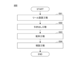
- the manufacturing method of the belt layer of this embodiment can include a reel installation step (S81), a drawing step (S82), an arrangement step (S83), and an embedding step (S84) as shown in the flow 800 in Fig. 9A.
- the manufacturing method of the belt layer of this embodiment will be described with reference to Figs. 8 and 9A.
- a number of reels 82 corresponding to the number of cords to be embedded in the rubber in the belt layer to be manufactured can be installed on the steel cord supplying device 81.
- Each reel 82 is wound with a steel cord.
- a twisted steel cord as the first steel cord is wound on the reel
- a solid steel cord as the second steel cord is wound on the reel.
- the coil diameter of the second steel cord may be 500 mm or more and 600 mm or less.
- the steel cord supplying device 81 is also called a reel supply, etc., and is a device that controls the rotation of the reels 82 and supplies the steel cord 80 wound on each reel 82 from each reel 82. Since FIG. 8 is a schematic diagram, only two reels 82 are shown.
- Pulling out process: S82 In the unwinding process, the steel cord 80 can be unwound from a plurality of reels 82 by a steel cord supplying device 81, and transported and supplied to the arrangement process.
- arrangement step: S83 In the arranging step, a plurality of steel cords 80 unwound from a plurality of reels 82 can be arranged in a line in a cross section perpendicular to the longitudinal direction of the steel cords.
- Multiple steel cords 80 can be arranged in a row, for example, by an arrangement device 83.
- the arrangement device 83 is not limited, but may have, for example, a guide plate 831 with a groove through which the steel cord 80 passes.
- the alignment device 83 may also have a grooved roll 832 as necessary.
- the grooved roll 832 can correct and align the position of the steel cord 80.
- multiple steel cords 80 are placed between rubber 84 using a calendar roll 85, and a calendar process is performed to produce a belt layer 86.
- the manufacturing method of the cord-rubber composite body of the present embodiment can have a first belt layer manufacturing step (S801), a second belt layer manufacturing step (S802), and a lamination step (S803).
- a first belt layer having a first rubber and a plurality of first steel cords embedded in the first rubber can be manufactured.
- a second belt layer having a second rubber and a plurality of second steel cords embedded in the second rubber can be manufactured.
- the first belt layer and the second belt layer can be laminated.
- the reel installation process S81 to the embedding process S85 shown in FIG. 9A are carried out, respectively, to manufacture the first belt layer and the second belt layer.
- the lamination step after laminating the first belt layer and the second belt layer, heating or the like may be performed as necessary to bond the layers together.
- the method for manufacturing the cord-rubber composite of the present embodiment it is possible to manufacture a cord-rubber composite according to one aspect of the present disclosure, which includes a single-wire steel cord and is capable of suppressing breakage when an external force is applied.
- the tire 90 of this embodiment can include a cord-rubber composite 10 according to one aspect of the present disclosure.
- Figure 10 shows a cross-sectional view of a tire 90 taken on a plane perpendicular to the outer circumference. Although Figure 10 shows only the portion to the left of the center line (CL), the tire 90 has the same structure continuing to the right of the CL, with the CL as the axis of symmetry.
- the tire 90 has a tread portion 91, a sidewall portion 92, and a bead portion 93.
- the tread portion 91 is the portion that comes into contact with the road surface.
- the bead portion 93 is located closer to the inner diameter of the tire 90 than the tread portion 91.
- the bead portion 93 is the portion that comes into contact with the rim of the vehicle's wheel.
- the sidewall portion 92 connects the tread portion 91 and the bead portion 93. When the tread portion 91 receives an impact from the road surface, the sidewall portion 92 elastically deforms and absorbs the impact.
- the tire 90 includes an inner liner 94, a carcass 95, a cord-rubber composite 10, and a bead wire 96.
- the inner liner 94 is made of rubber and seals the space between the tire 90 and the wheel.
- the carcass 95 forms the framework of the tire 90.
- the carcass 95 can be made of organic fibers such as polyester, nylon, or rayon, or steel cords, and rubber.
- the bead wire 96 is provided in the bead portion 93.
- the bead wire 96 receives the tensile force acting on the carcass.
- the cord-rubber composite 10 tightens the carcass 95 and increases the rigidity of the tread portion 91.
- the tire 90 has a cord-rubber composite 10 including a first belt layer 11 and a second belt layer 12.
- the first belt layer 11 is arranged to include at least one surface of the cord-rubber composite 10. That is, the first belt layer 11 is exposed on the surface of the cord-rubber composite 10.
- the cord-rubber composite 10 may be arranged so that the first belt layer 11 is located closer to the tread portion 91 than the other belt layers. By locating the first belt layer 11 closer to the tread portion 91 than the other belt layers, the durability and shock absorption performance of the tire 90 can be improved.
- the cord-rubber composite 10 contained in the tire 90 of this embodiment has a first belt layer 11, so that when an external force is applied to the tire 90 including the cord-rubber composite 10, the first steel cord 14, which is a twisted wire, expands and contracts, and is able to absorb impact. This makes it possible to prevent the tire 90 of this embodiment from being damaged when an external force is applied.
- the cord-rubber composite 10 contained in the tire 90 of this embodiment has a second belt layer 12, which reduces the thickness of the second belt layer 12 and makes the cord-rubber composite 10 and tire 90 lighter.
- the low load elongation of the steel cord is calculated using the following formula:
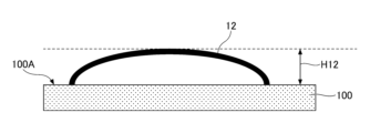
- the evaluation involves placing the cut second belt layer 12 on the upper surface 100A of a flat test stand 100, and measuring the maximum height H12 without applying any external force.
- the maximum height H12 is less than 5 mm, it is rated as A, if it is between 5 mm and 20 mm, it is rated as B, and if it is 20 mm or more, it is rated as C.
- a weight (not shown) is placed on a surface 111 of the second belt layer 12 opposite to the surface in contact with the test stand 110 so as to apply a load of 0.05 kg/ mm2 per unit area, and the second belt layer 12 is pressed against the test stand 110.
- a plate-shaped weight is used whose surface facing the second belt layer 12 to be evaluated has the same area as the surface 111 of the second belt layer 12.
- the second belt layer 12 is cut so that the surface in contact with the test stand 110 and the surface in contact with the weight 111 are both square, and is then used for testing.
- a reference line L is set parallel to the upper surface of the test stand 110 so as to pass through the center of the second steel cord 16A arranged at the end of the second belt layer 12 among the second steel cords 16 included in the second belt layer 12.
- the variation width along the thickness of the second belt layer 12 is measured for each of the second steel cords 16B, 16C, 16D, and 16E other than the reference second steel cord 16A.
- the variation width of each second steel cord 16 is obtained by measuring the distance between the reference line L along the thickness of the second belt layer 12 and the center of each second steel cord 16. In FIG. 11, the center of each second steel cord 16 is indicated by a black dot.
- the variation width of second steel cord 16B is L16B
- the variation width of second steel cord 16C is L16C
- the variation width of second steel cord 16D is L16D
- the variation width of second steel cord 16E is L16E.
- the average value of the variation widths L16B, L16C, L16D, and L16E is set as the variation width of the position of the second steel cord 16 in the second belt layer 12.
- the variation in the position of the second steel cord 16 is less than 0.3 mm, it is rated as A; if it is 0.3 mm or more but less than 0.5 mm, it is rated as B; if it is 0.5 mm or more, it is rated as C.
- the measured fracture energy is rated as C if it is 1 or less, B if it is greater than 1 but less than 1.1, and A if it is 1.1 or more.
- the cord-rubber composite 10 produced in the experimental example has a size of 100 mm x 50 mm.
- the first steel cord 14 and the second steel cord 16 in the cord-rubber composite 10 are arranged along the long side of the cord-rubber composite 10, i.e., the side with a length of 100 mm.
- the cord-rubber composite 10 is then set so that the center (midpoint) of the long side of the cord-rubber composite 10 touches the apex 120C of the measuring jig 120.
- both ends along the longitudinal direction of the cord-rubber composite 10 are bent toward both ends 120A, 120B of the base of the triangular prism measuring jig 120.
- the evaluator presses the cord-rubber composite 10 so that the entire surface facing the measuring jig 120 touches the sides connecting the apex 120C of the measuring jig 120 and both ends 120A, 120B, and removes the applied force after confirming that the shape has stabilized. That is, the evaluator presses both ends of the long side of the measuring jig 120 of the cord-rubber composite 10 so that they come into contact with both ends 120A and 120B of the measuring jig 120, and removes the applied force after confirming that the shape has stabilized.
- the cord-rubber composite 10 Since the shape of the cord-rubber composite 10 may change again when the evaluator removes the force, the cord-rubber composite 10 is left alone until the change in shape of the cord-rubber composite 10 stops. After the change in shape of the cord-rubber composite 10 stops, the area of the gap 121 formed between the cord-rubber composite 10 and the measuring jig 120 is measured when viewed along the longitudinal direction of the measuring jig 120.
- the area of the gap 121 is less than 0.3 mm2 , it is evaluated as A; when it is 0.3 mm2 or more and less than 0.5 mm2 , it is evaluated as B; and when it is 0.5 mm2 or more , it is evaluated as C.
- the evaluation is A
- the second belt layer 12 has the best ability to conform to the uneven shape, and the evaluation decreases in the order of B, C, etc.
- the evaluation is A or B
- the second belt layer 12 has a sufficiently high ability to conform to the uneven shape.
- a cord base material 70 is prepared by forming a copper layer and a zinc layer on the surface of a steel base material by plating, and the second steel cord is manufactured by performing a wire drawing process.
- the number of rolls 72, pressure, and groove shape in the device shown in Figure 7 are selected according to the desired cord diameter and coil diameter.
- the grooves in the rolls 72 have a constant curvature in a cross section perpendicular to the longitudinal direction of the groove.
- the evaluation results of the obtained second steel cord are shown in Table 1.
- (Manufacture of second belt layer) A second belt layer is manufactured by embedding a plurality of second steel cords in rubber so that the number of ends is 60/50 mm.
- the second steel cords used are those produced in this experimental example.
- the second belt layer is manufactured using the device shown in FIG. 8 and following flow 800 shown in FIG. 9A. Each step has already been explained, so the explanation will be omitted.
- Rubber 84 was manufactured from a rubber composition containing a rubber component and additives.
- the rubber composition contains 100 parts by mass of natural rubber as the rubber component.
- the rubber composition also contains, as additives, 60 parts by mass of carbon black, 7 parts by mass of sulfur, 0.5 parts by mass of vulcanization accelerator, 8 parts by mass of zinc oxide, and 2 parts by mass of cobalt stearate as an organic cobalt acid per 100 parts by mass of the rubber component.
- the second belt layer 12 is prototyped in advance using the second steel cords produced in this experimental example, and the variation in the position of the second steel cords 16 in the second belt layer 12 is measured in the positional accuracy evaluation method.
- a preset thickness constant is added to the measured variation in the position of the second steel cords 16 in the second belt layer 12 so that the second steel cords 16 can be embedded, to obtain the rubber thickness.
- the manufacturing conditions are selected so that the thickness of the rubber placed above and below the second steel cord 16 is the rubber thickness determined in advance.
- the thicknesses of the rubber placed above and below the second steel cord 16 correspond to thickness T121 and thickness T122 in Figure 1.
- one of the two second belt layers 12 is referred to as the first belt layer, and the second steel cord included in the first belt layer is referred to as the first steel cord.
- the first belt layer 11 has multiple first steel cords 14 embedded in rubber so that the ends are 60 per 50 mm.
- the first steel cords 14 are twisted wires having the structure shown in Tables 1 and 2.
- the wire 141 of the first steel cord 14 has a steel wire and a brass plating film disposed on the surface of the wire.
- the composition of the brass plating film is shown in Tables 1 and 2.
- the second belt layer 12 in each experimental example uses a second steel cord that has been processed so that the cord diameter and coil diameter are the desired values.
- the second belt layer 12 is manufactured under the same conditions and procedures as in experimental example 1.
- the first belt layer 11 and the second belt layer 12 were prototyped in advance using the first steel cord and the second steel cord of each experimental example.
- the rubber thickness of each belt layer was then determined using the same procedure as for the second belt layer of experimental example 1.
- the manufacturing conditions are selected so that the thickness of the rubber placed above and below the first steel cord 14 and the second steel cord 16 is the rubber thickness that was determined in advance.
- the thicknesses of the rubber placed above and below the first steel cord 14 correspond to thickness T111 and thickness T112 in Figure 1.
Landscapes
- Engineering & Computer Science (AREA)
- Mechanical Engineering (AREA)
- Ropes Or Cables (AREA)
- Tires In General (AREA)
Priority Applications (3)
| Application Number | Priority Date | Filing Date | Title |
|---|---|---|---|
| JP2025516511A JPWO2024224687A1 (https=) | 2023-04-25 | 2023-12-20 | |
| CN202380095416.3A CN120826509A (zh) | 2023-04-25 | 2023-12-20 | 帘线-橡胶复合体、帘线-橡胶复合体的制造方法、轮胎 |
| DE112023006262.5T DE112023006262T5 (de) | 2023-04-25 | 2023-12-20 | Cord-Gummi-Verbundstruktur, Verfahren zur Herstellung einer Cord-Gummi-Verbundstruktur und Reifen |
Applications Claiming Priority (2)
| Application Number | Priority Date | Filing Date | Title |
|---|---|---|---|
| JP2023071821 | 2023-04-25 | ||
| JP2023-071821 | 2023-04-25 |
Publications (1)
| Publication Number | Publication Date |
|---|---|
| WO2024224687A1 true WO2024224687A1 (ja) | 2024-10-31 |
Family
ID=93255876
Family Applications (1)
| Application Number | Title | Priority Date | Filing Date |
|---|---|---|---|
| PCT/JP2023/045812 Ceased WO2024224687A1 (ja) | 2023-04-25 | 2023-12-20 | コード-ゴム複合体、コード-ゴム複合体の製造方法、タイヤ |
Country Status (4)
| Country | Link |
|---|---|
| JP (1) | JPWO2024224687A1 (https=) |
| CN (1) | CN120826509A (https=) |
| DE (1) | DE112023006262T5 (https=) |
| WO (1) | WO2024224687A1 (https=) |
Citations (7)
| Publication number | Priority date | Publication date | Assignee | Title |
|---|---|---|---|---|
| JP2000154482A (ja) * | 1998-11-16 | 2000-06-06 | Tokyo Seiko Co Ltd | 単線スチールコードの製造方法及び製造装置 |
| JP2000272306A (ja) * | 1999-03-23 | 2000-10-03 | Sumitomo Rubber Ind Ltd | チューブレスタイヤ |
| JP2001180221A (ja) * | 1999-12-22 | 2001-07-03 | Sumitomo Rubber Ind Ltd | 空気入りラジアルタイヤ |
| JP2003291608A (ja) * | 2002-04-03 | 2003-10-15 | Yokohama Rubber Co Ltd:The | 空気入りラジアルタイヤ |
| JP2004351944A (ja) * | 2003-05-26 | 2004-12-16 | Toyo Tire & Rubber Co Ltd | 空気入りラジアルタイヤ |
| JP2004359198A (ja) * | 2003-06-09 | 2004-12-24 | Bridgestone Corp | 空気入りタイヤ及びこれに用いる補強素子の製造方法 |
| JP2007253848A (ja) * | 2006-03-24 | 2007-10-04 | Bridgestone Corp | 空気入りタイヤ |
Family Cites Families (2)
| Publication number | Priority date | Publication date | Assignee | Title |
|---|---|---|---|---|
| AU2013203062C1 (en) | 2013-03-15 | 2018-06-28 | Takeda Pharmaceutical Company Limited | Subcutaneous administration of adamts13 |
| JP6848319B2 (ja) | 2016-10-06 | 2021-03-24 | 横浜ゴム株式会社 | 空気入りタイヤ |
-
2023
- 2023-12-20 JP JP2025516511A patent/JPWO2024224687A1/ja active Pending
- 2023-12-20 WO PCT/JP2023/045812 patent/WO2024224687A1/ja not_active Ceased
- 2023-12-20 DE DE112023006262.5T patent/DE112023006262T5/de active Pending
- 2023-12-20 CN CN202380095416.3A patent/CN120826509A/zh active Pending
Patent Citations (7)
| Publication number | Priority date | Publication date | Assignee | Title |
|---|---|---|---|---|
| JP2000154482A (ja) * | 1998-11-16 | 2000-06-06 | Tokyo Seiko Co Ltd | 単線スチールコードの製造方法及び製造装置 |
| JP2000272306A (ja) * | 1999-03-23 | 2000-10-03 | Sumitomo Rubber Ind Ltd | チューブレスタイヤ |
| JP2001180221A (ja) * | 1999-12-22 | 2001-07-03 | Sumitomo Rubber Ind Ltd | 空気入りラジアルタイヤ |
| JP2003291608A (ja) * | 2002-04-03 | 2003-10-15 | Yokohama Rubber Co Ltd:The | 空気入りラジアルタイヤ |
| JP2004351944A (ja) * | 2003-05-26 | 2004-12-16 | Toyo Tire & Rubber Co Ltd | 空気入りラジアルタイヤ |
| JP2004359198A (ja) * | 2003-06-09 | 2004-12-24 | Bridgestone Corp | 空気入りタイヤ及びこれに用いる補強素子の製造方法 |
| JP2007253848A (ja) * | 2006-03-24 | 2007-10-04 | Bridgestone Corp | 空気入りタイヤ |
Also Published As
| Publication number | Publication date |
|---|---|
| JPWO2024224687A1 (https=) | 2024-10-31 |
| CN120826509A (zh) | 2025-10-21 |
| DE112023006262T5 (de) | 2026-03-19 |
Similar Documents
| Publication | Publication Date | Title |
|---|---|---|
| CN102471998B (zh) | 原地橡胶处理的基础线股为双层帘线的多线股帘线 | |
| CN101910506B (zh) | 适用于轮胎带束层的就地被涂覆上橡胶的分层绳索 | |
| CN102105634B (zh) | 用于轮胎的胎体增强件的就地被涂覆橡胶的分层缆线 | |
| CN102472001B (zh) | 原地橡胶处理的基础线股为双层帘线的多线股帘线 | |
| JP5632853B2 (ja) | 現場ゴム引きタイヤの3層コードを製造する方法及び装置 | |
| KR101788994B1 (ko) | 스트립 형상 스틸 코드 | |
| US20120125512A1 (en) | Three-Layer Cord, Rubberized In Situ, For A Tire Carcass Reinforcement | |
| JP5591908B2 (ja) | 現場ゴム引き形式の3層コードを製造する方法及び装置 | |
| US20150329995A1 (en) | Metal cord comprising layers having high penetrability | |
| US20120186715A1 (en) | Three-Layer Steel Cord that is Rubberized in Situ and has a 3+M+N Structure | |
| JP7367899B1 (ja) | スチールコード、コード-ゴム複合体、タイヤ | |
| JP7670245B1 (ja) | スチールコード、コード-ゴム複合体、タイヤ | |
| EP3315328B1 (en) | Cable bead for pneumatic tire and pneumatic tire having the same | |
| WO2024224687A1 (ja) | コード-ゴム複合体、コード-ゴム複合体の製造方法、タイヤ | |
| JP2008291380A (ja) | ゴム物品補強用コードおよびタイヤ | |
| JP7540621B1 (ja) | スチールコード、コード-ゴム複合体、およびタイヤ | |
| WO2024176640A1 (ja) | スチールコード、コード-ゴム複合体、およびタイヤ | |
| JPH1088488A (ja) | ゴム補強用スチールコードおよびラジアルタイヤ | |
| JP5656346B2 (ja) | ゴム−スチールコード複合体の製造方法 | |
| EP4088921B1 (en) | Method of manufacturing rubber composite and method of manufacturing tire | |
| WO2025047070A1 (ja) | スチールコード、タイヤ | |
| WO2026009644A1 (ja) | コード-ゴム複合体、タイヤ |
Legal Events
| Date | Code | Title | Description |
|---|---|---|---|
| 121 | Ep: the epo has been informed by wipo that ep was designated in this application |
Ref document number: 23935458 Country of ref document: EP Kind code of ref document: A1 |
|
| WWE | Wipo information: entry into national phase |
Ref document number: 2025516511 Country of ref document: JP |
|
| WWE | Wipo information: entry into national phase |
Ref document number: CN2023800954163 Country of ref document: CN Ref document number: 202380095416.3 Country of ref document: CN |
|
| WWE | Wipo information: entry into national phase |
Ref document number: 2501007134 Country of ref document: TH |
|
| WWP | Wipo information: published in national office |
Ref document number: 202380095416.3 Country of ref document: CN |
|
| WWE | Wipo information: entry into national phase |
Ref document number: 112023006262 Country of ref document: DE |
|
| WWP | Wipo information: published in national office |
Ref document number: 112023006262 Country of ref document: DE |
|
| 122 | Ep: pct application non-entry in european phase |
Ref document number: 23935458 Country of ref document: EP Kind code of ref document: A1 |