WO2024224600A1 - 制動制御方法及び制動制御装置 - Google Patents
制動制御方法及び制動制御装置 Download PDFInfo
- Publication number
- WO2024224600A1 WO2024224600A1 PCT/JP2023/016855 JP2023016855W WO2024224600A1 WO 2024224600 A1 WO2024224600 A1 WO 2024224600A1 JP 2023016855 W JP2023016855 W JP 2023016855W WO 2024224600 A1 WO2024224600 A1 WO 2024224600A1
- Authority
- WO
- WIPO (PCT)
- Prior art keywords
- braking force
- vehicle
- brake
- actuator
- braking
- Prior art date
- Legal status (The legal status is an assumption and is not a legal conclusion. Google has not performed a legal analysis and makes no representation as to the accuracy of the status listed.)
- Ceased
Links
Images






Classifications
-
- B—PERFORMING OPERATIONS; TRANSPORTING
- B60—VEHICLES IN GENERAL
- B60T—VEHICLE BRAKE CONTROL SYSTEMS OR PARTS THEREOF; BRAKE CONTROL SYSTEMS OR PARTS THEREOF, IN GENERAL; ARRANGEMENT OF BRAKING ELEMENTS ON VEHICLES IN GENERAL; PORTABLE DEVICES FOR PREVENTING UNWANTED MOVEMENT OF VEHICLES; VEHICLE MODIFICATIONS TO FACILITATE COOLING OF BRAKES
- B60T7/00—Brake-action initiating means
- B60T7/12—Brake-action initiating means for automatic initiation; for initiation not subject to will of driver or passenger
-
- B—PERFORMING OPERATIONS; TRANSPORTING
- B60—VEHICLES IN GENERAL
- B60T—VEHICLE BRAKE CONTROL SYSTEMS OR PARTS THEREOF; BRAKE CONTROL SYSTEMS OR PARTS THEREOF, IN GENERAL; ARRANGEMENT OF BRAKING ELEMENTS ON VEHICLES IN GENERAL; PORTABLE DEVICES FOR PREVENTING UNWANTED MOVEMENT OF VEHICLES; VEHICLE MODIFICATIONS TO FACILITATE COOLING OF BRAKES
- B60T8/00—Arrangements for adjusting wheel-braking force to meet varying vehicular or ground-surface conditions, e.g. limiting or varying distribution of braking force
- B60T8/17—Using electrical or electronic regulation means to control braking
- B60T8/172—Determining control parameters used in the regulation, e.g. by calculations involving measured or detected parameters
Definitions
- the present invention relates to a braking control method and a braking control device.
- the problem that this invention aims to solve is to provide a braking control method and a braking control device that can prevent the life of the actuator that operates the brakes from being shortened.
- the present invention solves the above problem in an electric parking brake equipped with a first actuator that operates a first brake on at least one of the left front and left rear wheels of a vehicle with a first braking force, and a second actuator that operates a second brake on at least one of the right front and right rear wheels with a second braking force, by controlling the first actuator and the second actuator so that one of the first braking force and the second braking force is smaller than the other when the vehicle is parked and it is determined that the inclination of the vehicle is smaller than a predetermined value.
- the present invention makes it possible to prevent the lifespan of the actuator that activates the brakes from being shortened.
- FIG. 1 is a plan view showing an embodiment of a vehicle equipped with an electric parking brake according to the present invention.
- 2 is a plan view showing an example of a brake provided on a left rear wheel of the vehicle shown in FIG. 1 .
- 1 is a block diagram showing one embodiment of an electric parking brake according to the present invention;
- FIG. 2 is a side view showing an example of the inclination of the vehicle shown in FIG. 1 .
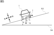
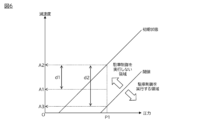
- FIG. 4 is a front view showing another example of the inclination of the vehicle in FIG. 4 is an example of a map showing a relationship between brake fluid pressure and vehicle deceleration in the embodiment. 4 is a flowchart showing an example of a processing procedure in the electric parking brake of FIG. 3 .
- FIG. 7 is a flowchart showing another example of the processing procedure in the electric parking brake of FIG. 3 .
- 9 is a flowchart showing an example of a subroutine of step S11 in FIG. 8 .
- 10 is a flowchart showing another example of the subroutine of step S11 in FIG. 8 .
- 10 is a flowchart showing still another example of the subroutine of step S11 in FIG. 8 .
- 10 is a flowchart showing yet another example of the subroutine of step S11 in FIG. 8 .
- 10 is a flowchart showing yet another example of the subroutine of step S11 in FIG. 8 .
- 10 is a flowchart showing yet another example of the subroutine of step S11 in FIG. 8 .
- 10 is a flowchart showing yet another example of the subroutine of step S11 in FIG. 8 .
- 10 is a flowchart showing yet another example of the subroutine of step S11 in FIG. 8 .
- FIG. 1 is a plan view showing an embodiment of a vehicle equipped with an electric parking brake according to the present invention.
- the electric parking brake is a device that stops the movement of the vehicle (specifically, the rotation of the wheels, the propeller shaft, etc.) by an electric actuator such as a motor, and parks the vehicle.
- the vehicle is not particularly limited, and includes vehicles of any drive system.
- the vehicle 1 includes a left front wheel 11, a left rear wheel 12, a right front wheel 21, a right rear wheel 22, actuators 31, 32, 41, 42, a brake control device 50, an acceleration sensor 61, a temperature sensor 62, and a parking switch 81.
- the rotation of the wheels refers to the rotation of the wheels in the circumferential direction, unless otherwise specified.
- the left front wheel 11, left rear wheel 12, right front wheel 21, and right rear wheel 22 are each attached to the suspension (not shown) of the vehicle 1 via a hub, and a brake is provided for each of the left front wheel 11, left rear wheel 12, right front wheel 21, and right rear wheel 22 to prevent rotation in the circumferential direction.
- the brake that prevents rotation of the left front wheel 11 and left rear wheel 12 of the vehicle 1 is referred to as the first brake
- the brake that prevents rotation of the right front wheel 21 and right rear wheel 22 is referred to as the second brake.
- a force in the opposite direction to the direction of travel is generated between each wheel and the ground (or road surface) on which the vehicle 1 is in contact in order to stop the rotation of the wheels.
- This force is called the braking force, and is calculated, for example, by dividing the braking torque around the vehicle's axle by the radius of the tire.
- the braking force of the first brake is called the first braking force
- the braking force of the second brake is called the second braking force.
- Actuators 31, 32, 41, 42 are mechanical elements that activate brakes to stop the rotation of left front wheel 11, left rear wheel 12, right front wheel 21, and right rear wheel 22, and are, for example, motors, electromagnetic solenoids, etc. Actuators 31, 32, 41, 42 activate or stop the brakes according to control signals output from brake control device 50. Actuators 31, 32, 41, 42 can be placed in appropriate positions within a range in which the brakes can be activated. In this embodiment, actuators 31, 32 that activate the first brake are referred to as first actuators, and actuators 41, 42 that activate the second brake are referred to as second actuators.
- the electric parking brake includes a first actuator that operates a first brake on at least one of the left front wheel 11 and the left rear wheel 12 of the vehicle 1 with a first braking force, and a second actuator that operates a second brake on at least one of the right front wheel 21 and the right rear wheel 22 with a second braking force.
- the brake control device 50 can control the first actuator and the second actuator independently. Note that, in the vehicle 1 shown in FIG. 1, actuators for the electric parking brake are provided on all wheels, but it is not necessary to provide actuators on all wheels. For example, actuators 31, 41 may be provided only on the left front wheel 11 and the right front wheel 21, and actuators 32, 42 may be provided only on the left rear wheel 12 and the right rear wheel 22.
- the braking control device 50 is a device for stopping the movement of the vehicle 1 by controlling and cooperating with the devices that make up the electric parking brake.
- the braking control device 50 is, for example, a computer, and includes a CPU (Central Processing Unit) which is a processor, a ROM (Read Only Memory) in which programs are stored, and a RAM (Random Access Memory) which functions as an accessible storage device.
- the CPU is an operating circuit for executing the programs stored in the ROM and realizing the functions of the braking control device 50.
- the acceleration sensor 61 is a device that detects the acceleration applied to the vehicle 1, and any known acceleration sensor, such as a capacitance type, can be used without any particular restrictions.
- the acceleration sensor 61 detects the direction of gravity (vertical direction) and the front-rear, left-right, and up-down directions of the vehicle, as well as the amount of movement, speed, and direction of movement of the vehicle 1.
- the temperature sensor 62 is a device that detects the outside air temperature of the vehicle 1, and any known temperature sensor can be used without any particular restrictions.
- the acceleration sensor 61 and the temperature sensor 62 can be placed at appropriate positions within ranges where the acceleration and outside air temperature can be appropriately detected, respectively.
- the acceleration sensor 61 corresponds to the detection means of the present invention that detects the inclination of the vehicle 1.
- the parking switch 81 is a switch that is operated to activate the electric parking brake, and is provided around the driver's seat of the vehicle 1.
- the parking switch 81 is, for example, a switch located on the instrument panel, a pedal located to the left of the driver's feet, or a button located on the center console.
- FIG. 2 is a plan view showing an example of a brake provided on the left rear wheel 12 of the vehicle 1.
- the brake 70 includes a disc rotor 71, a brake caliper 72, brake pads 73, 74, a piston 75, a cylinder 76, a pressure sensor 77, and a speed sensor 78.
- the left front wheel 11, the right front wheel 21, and the right rear wheel 22 are also provided with brakes similar to the brake 70 shown in Figure 2.
- the disc rotor 71 has a hub 71a to which the left rear wheel 12 is attached, and rotates together with the left rear wheel 12 in the circumferential direction of the left rear wheel 12 around an axle (not shown).
- a brake caliper 72 that stops the rotation of the disc rotor 71 is provided on the front side of the vehicle of the disc rotor 71.
- the brake caliper 72 has a pair of brake pads 73, 74, a piston 75, and a cylinder 76.
- the pair of brake pads 73, 74 are arranged facing each other on both sides of the disc rotor 71, sandwiching the disc rotor 71.
- a small gap (e.g., 0.1 mm or less) is provided between the disc rotor 71 and the brake pads 73, 74.
- the cylinder 76 is provided inside the brake caliper 72, and contains the piston 75 and brake fluid.
- the pressure sensor 77 is a device that detects the pressure (hydraulic pressure) of the brake fluid contained in the cylinder 76, and any known pressure sensor can be used without particular restrictions.
- the speed sensor 78 is a device that detects the rotational speed of the disc rotor 71, and any known speed sensor can be used without particular restrictions.
- the pressure sensor 77 and the speed sensor 78 can be placed in any appropriate position within a range where the pressure and rotational speed can be appropriately detected, respectively.
- the actuator 32 pushes the piston 75 towards the left side of the vehicle.
- This pushing of the piston 75 pressurizes the brake fluid in the cylinder 76, applying a force towards the left side of the vehicle to the brake pad 74.
- the brake pad 74 which has received force from the brake fluid, moves towards the left side of the vehicle and, together with the brake pad 73 held by the brake caliper 72, presses against the disc rotor 71, stopping the rotation of the disc rotor 71.
- the actuator 32 returns the piston 75 to the right side of the vehicle, releasing the brake fluid pressure.
- the brake pad 74 moves to the right side of the vehicle and returns to its original position. Then, the brake pads 73 and 74 separate from the disc rotor 71, allowing the disc rotor 71 to rotate freely.
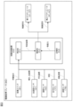
- FIG. 3 is a block diagram showing one embodiment of an electric parking brake according to the present invention.
- an electric parking brake 80 includes a parking switch 81, an acceleration sensor 61, a temperature sensor 62, a pressure sensor 77, a speed sensor 78, a braking control device 50, first actuators 31, 32, and second actuators 41, 42. These devices are connected by a Controller Area Network (CAN) or other in-vehicle LAN, and can transmit and receive information to and from each other.
- CAN Controller Area Network
- the braking control device 50 has a braking function that stops the movement of the vehicle 1.
- a program for implementing the braking function is stored in the ROM of the braking control device 50, and the braking function is implemented by the CPU executing the program stored in the ROM.
- FIG. 3 shows the determination unit 51, control unit 52, and memory unit 53 as functional blocks that implement the braking function. The functions of each functional block will be explained below with reference to FIG. 3.
- the determination unit 51 has a function of determining whether or not the inclination of the vehicle 1 is less than a predetermined value.
- an operation command to operate the electric parking brake 80 is output to the braking control device 50.
- the braking control device 50 uses the function of the determination unit 51 to determine whether or not the parking switch 81 has been operated, and if an operation command is obtained, it determines that the parking switch 81 has been operated. On the other hand, if an operation command is not obtained, it determines that the parking switch 81 has not been operated.
- the braking control device 50 may also estimate whether the driving scene of the vehicle 1 is a parking scene. For example, the current position of the vehicle 1 is acquired from a positioning system (not shown), and based on map information and the information on the current position of the vehicle 1, it determines whether the vehicle 1 is driving in a parking lot. If it is determined that the vehicle 1 is driving in a parking lot, it estimates that the driving scene of the vehicle 1 is a parking scene. In contrast, if it is determined that the vehicle 1 is driving on a normal road, it estimates that the driving scene of the vehicle 1 is not a parking scene.
- the brake control device 50 estimates that the driving scene of the vehicle 1 is a parking scene and/or receives an activation command from the parking switch 81, it determines that the vehicle 1 is parking, and obtains the inclination of the vehicle 1 from the acceleration sensor 61, which is a detection means for detecting the inclination of the vehicle 1, by the function of the determination unit 51.
- the acceleration sensor 61 detects the direction of gravity and the fore-aft direction of the vehicle, and calculates the inclination of the vehicle 1 from the angle formed between the direction of gravity and the fore-aft direction of the vehicle.
- the brake control device 50 may obtain the direction of gravity and the fore-aft direction of the vehicle from the acceleration sensor 61, which is a detection means for detecting the inclination of the vehicle 1, and calculate the inclination of the vehicle 1 from the two obtained directions.
- FIG. 4 is a side view showing an example of the inclination of the vehicle 1.
- the ground 91 on which the vehicle 1 is standing is inclined in the fore-and-aft direction of the vehicle 1, and the vehicle 1 is parked with the rear side lower than the front side (in a state of leaning backwards).
- the brake control device 50 obtains the direction of gravity (arrow G) and the fore-and-aft direction of the vehicle (arrow H) from the acceleration sensor 61, and calculates the angle b, which is the inclination of the vehicle 1 (or the ground 91) with respect to the horizontal plane 92, by subtracting 90 from the minor angle a formed by the arrows G and H.
- the brake control device 50 may also obtain or calculate the left-right tilt of the vehicle 1 in addition to the forward-rearward tilt of the vehicle 1. For example, as shown in FIG. 5, when the ground 93 on which the vehicle 1 is in contact is tilted in the left-right direction of the vehicle 1 and the vehicle 1 is parked with the left side lower than the right side (tilted to the left), the brake control device 50 obtains the direction of gravity (arrow G) and the left-right direction of the vehicle (arrow I) from the acceleration sensor 61, which is a detection means for detecting the tilt of the vehicle 1, and calculates the angle d, which is the tilt of the vehicle 1 (or the ground 93) with respect to the horizontal plane 94, by subtracting 90 from the minor angle c formed by the arrows G and I. Note that the ground includes the road surface.
- the brake control device 50 judges whether the inclination acquired from the acceleration sensor 61, which is a means for detecting the inclination of the vehicle 1, is less than a predetermined value.
- the predetermined value can be set to an appropriate value within a range in which the movement of the vehicle 1 can be appropriately stopped by either the first brake on the left side of the vehicle or the second brake on the right side of the vehicle, for example, 10° to 30°. If the brake control device 50 judges that the acquired inclination is less than the predetermined value, it executes a first control that controls the first actuator and the second actuator so that one of the first braking force and the second braking force is smaller than the other in order to suppress a shortening of the actuator life.
- the second control operates the first actuator and the second actuator and sets the first braking force and the second braking force so that the difference between the first braking force and the second braking force is less than the predetermined braking force in order to appropriately stop the movement of the vehicle 1.
- the second control is also called parking control.
- the control unit 52 has a function of executing the first control or the second control when it is determined that the inclination of the vehicle 1 is less than a predetermined value.
- the brake control device 50 stops one of the first actuator and the second actuator. Stopping the first (second) actuator means that when a control signal to stop the actuator is input, the actuator is not operated any further. In other words, when the brake is not applied, the actuator is not operated, and when the brake is applied, the actuator is controlled so that the brake pad does not press against the disc rotor.
- the brake control device 50 when the first brake and the second brake are not applied, the brake control device 50 operates only one of the first actuator and the second actuator. When only one of the first actuator and the second actuator is operated, the load on the actuator can be further reduced.
- the brake control device 50 sets either the first braking force or the second braking force set in the first control as the braking force of the first brake and the second brake.
- the brake control device 50 sets a predetermined percentage (e.g., 60% to 90%) of the maximum braking force of the first brake and the second brake as the braking force of the first brake and the second brake, which is previously set.
- the brake control device 50 sets the first braking force and the second braking force to the same value.
- the brake control device 50 may set the first braking force and the second braking force in the first control so that the difference between the first braking force and the second braking force is equal to or greater than a predetermined braking force.
- the brake control device 50 may also set the first braking force and the second braking force in the first control so that the difference between the first braking force and the second braking force is equal to or greater than a predetermined braking force, and may also set the first braking force and the second braking force in the second control so that the difference between the first braking force and the second braking force is less than the predetermined braking force.
- the predetermined braking force can be set to an appropriate value within a range in which the load on the actuator can be suppressed, for example, and is, as one example, a braking force that is a predetermined percentage (for example, 60% to 90%) of the maximum braking force of the first brake and the second brake.
- the brake control device 50 executes the first control by the function of the control unit 52. Specifically, only the actuator 32 is operated to stop the rotation of the left rear wheel 12. The first braking force is set to an appropriate value within a range in which the vehicle 1 does not move on the ground surface 91.
- the brake control device 50 executes the second control by the function of the control unit 52. Specifically, the actuators 32, 42 are operated to stop the rotation of the left rear wheel 12 and the right rear wheel 22. The braking forces of the first brake and the second brake are set to appropriate values within a range in which the vehicle 1 does not move on the ground surface 91.
- the memory unit 53 has a function of storing the first braking force and the second braking force in correspondence with each other.
- the brake control device 50 uses the function of the memory unit 53 to store in ROM or the like the first braking force and the second braking force set when the actuator is activated in correspondence with each other. Thereafter, when the actuator is stopped and at least one of the first actuator and the second actuator is newly activated, if it is determined that the inclination of the vehicle 1 is less than a predetermined value, the control unit 52 uses the function of the previous first braking force and second braking force that were set when at least one of the first actuator and the second actuator was last activated. Then, the current first braking force and second braking force are set based on the previously acquired first braking force and second braking force.
- the current first braking force is set smaller than the current second braking force
- the current first braking force is set larger than the current second braking force.
- the previous first braking force and second braking force are the same value
- the first braking force and second braking force that were set the last time the first control was executed are obtained, and the current first braking force and second braking force are set based on the obtained first braking force and second braking force.
- the brake control device 50 may determine whether the vehicle 1 is loaded onto a transporter transporting the vehicle 1, and may execute the second control if it is determined that the vehicle 1 is loaded onto a transporter. For example, if it is detected from the inclination and acceleration of the vehicle 1 acquired from the acceleration sensor 61 that acceleration in the left-right direction has been applied to the vehicle 1 in a state of inclination in the forward-backward direction, it determines that the vehicle 1 is loaded onto a transporter, and executes the second control. On the other hand, if it is determined that the vehicle 1 is not loaded onto a transporter, it does not execute the second control. Examples of transporters include vehicle transporters and tow trucks.
- the brake control device 50 may determine, by the function of the determination unit 51, whether or not the vehicle 1 is in a state in which at least one of the first braking force and the second braking force is reduced (hereinafter also referred to as a reduced braking force state). Then, if it is determined that the vehicle 1 is in a reduced braking force state, the brake control device 50 may execute a second control by the function of the control unit 52 in order to appropriately stop the movement of the vehicle 1.
- the reduced braking force state refers to a state in which the original braking force corresponding to the operation of the actuator cannot be obtained due to the driving environment around the vehicle 1, the state of the brakes 70, the state of the ground (or road surface), etc.
- the brake control device 50 estimates the temperature of the brake pads of the first and second brakes, determines whether the estimated temperature is equal to or higher than the fade temperature, and executes the second control if it determines that the estimated temperature is equal to or higher than the fade temperature. In contrast, if it determines that the estimated brake pad temperature is lower than the fade temperature, it does not execute the second control.
- the fade temperature is the temperature at which the friction coefficient of the brake pads begins to decrease, and is, for example, between 250°C and 350°C.
- the brake control device 50 estimates the temperature of the brake pads based on the deceleration of the vehicle 1 when the brakes are applied and the duration of brake application. For example, the relationship between the deceleration of the vehicle 1, the duration of brake application, and the temperature rise of the brake pads is determined in advance. Also, the relationship between the heat dissipation time when the brakes are not applied and the temperature drop of the brake pads is determined in advance. Then, the amount of temperature change indicating how much the temperature of the brake pads has risen or fallen from time T1 to time T2, a predetermined time after time T1, is calculated. The temperature of the brake pads at time T2 is estimated by adding the calculated amount of temperature change to the temperature of the brake pads at time T1.
- the above-mentioned predetermined time is, for example, a time according to the computing power of the CPU of the brake control device 50.
- the brake control device 50 monitors the temperature of the brake pads by repeatedly estimating the temperature of the brake pads at predetermined time intervals.
- the initial brake temperature is, for example, the outside air temperature around the vehicle 1 obtained from the temperature sensor 62, and when starting a new estimation of the brake pad temperature, the initial brake temperature may be the most recently estimated temperature of the brake pads.
- the brake control device 50 acquires the brake fluid pressure (hereinafter also referred to as the actual pressure) of the first brake and the second brake when at least one of the first brake and the second brake is activated, and the deceleration of the vehicle 1 (hereinafter also referred to as the actual deceleration).
- the brake control device 50 acquires the deceleration corresponding to the brake fluid pressure when the brakes are activated (hereinafter also referred to as the deceleration corresponding to the pressure).
- the second control determines whether the actual deceleration is lower than the deceleration corresponding to the pressure by a predetermined deceleration or more, and if it is determined that the actual deceleration is lower than the deceleration corresponding to the pressure by the predetermined deceleration or more, it executes the second control. In other words, if the difference between the actual deceleration and the deceleration corresponding to the pressure is greater than the predetermined deceleration, it executes the second control. On the other hand, if it is determined that the actual deceleration is lower than the deceleration corresponding to the pressure by less than the predetermined deceleration, it does not execute the second control.
- the relationship between the brake fluid pressure and the deceleration of the vehicle 1 is pre-recorded in the ROM of the braking control device 50, for example, as a map showing the relationship between the brake fluid pressure and the deceleration of the vehicle 1.
- the predetermined deceleration is, for example, the deceleration at which the second control needs to stop the movement of the vehicle 1, and is specifically 60% to 80% of the deceleration corresponding to the pressure in the initial state (shipped state). In other words, when the actual deceleration obtained from the acceleration sensor 61 becomes 20% to 40% of the initial value of the deceleration corresponding to the pressure, the second control is executed.
- FIG. 6 is an example of a map showing the relationship between brake fluid pressure and vehicle deceleration.
- the horizontal axis of the map shown in FIG. 6 indicates pressure, and the vertical axis indicates the deceleration of vehicle 1.
- the map sets at least the relationship between brake fluid pressure and vehicle deceleration in the initial state (shipment state), and a threshold value that divides the area where parking control (second control) is performed from the area where parking control is not performed.
- the area to the lower right of the line indicating the threshold value is the area where second control is performed
- the area to the upper left of the line indicating the threshold value is the area where second control is not performed.
- the brake control device 50 determines that the difference between the actual deceleration and the deceleration corresponding to the pressure is less than the predetermined deceleration, and does not execute the second control.
- the brake control device 50 may obtain the outside air temperature of the vehicle 1 from the temperature sensor 62 while executing the first control, determine whether the outside air temperature is below a predetermined temperature, and execute the second control if it is determined that the outside air temperature is below the predetermined temperature.
- the predetermined temperature is, for example, a temperature at which the actuator's operating efficiency begins to decrease due to low temperatures, specifically, -40°C to -10°C.
- the brake control device 50 may obtain the operating state of the wipers of the vehicle 1 while executing the first control, determine whether the wipers are operating, and execute the second control if it is determined that the wipers are operating.
- the brake control device 50 may, for example, while executing the first control, obtain the acceleration of the vehicle 1 from the acceleration sensor 61, determine whether the acceleration of the vehicle 1 is equal to or greater than a predetermined acceleration, and if it determines that the acceleration is equal to or greater than the predetermined acceleration, execute the second control.
- the predetermined acceleration can be set to an appropriate value within a range in which it is possible to detect contact of an object with the vehicle 1, and may be, for example, 0.5 G to 2.0 G.
- the brake control device 50 may also, for example, while executing the first control, determine whether the inclination of the vehicle 1 is equal to or greater than a predetermined value, and if it determines that the inclination of the vehicle 1 is equal to or greater than the predetermined value, execute the second control.
- the brake control device 50 When at least one of the first and second brakes is activated, the brake control device 50 obtains the rotational speeds of the left front wheel 11, left rear wheel 12, right front wheel 21, and right rear wheel 22 from the speed sensor 78, and determines whether or not at least one of these wheels is rotating. If it is determined that at least one of the left front wheel 11, left rear wheel 12, right front wheel 21, and right rear wheel 22 is rotating, the brake control device 50 executes the second control. On the other hand, if it is determined that none of the wheels are rotating, the brake control device 50 does not execute the second control.
- the braking control device 50 may determine whether the first control is being executed, and if it is determined that the first control is being executed, determine whether the vehicle 1 is in a state of reduced braking force. The braking control device 50 may also determine whether the brakes of the vehicle 1 are operating, and if it is determined that the brakes of the vehicle 1 are not operating, determine whether the vehicle 1 is in a state of reduced braking force.
- FIG. 7 is an example of a flowchart showing information processing executed in the electric parking brake 80 of this embodiment.
- the processing described below is executed by a processor (CPU) included in the brake control device 50.
- step S1 the function of the determination unit 51 is used to determine whether or not the parking switch 81 has been operated. If it is determined that the parking switch 81 has not been operated, step S1 is repeated. On the other hand, if it is determined that the parking switch 81 has been operated, the process proceeds to step S2.
- step S2 the inclination of the vehicle 1 is obtained from the acceleration sensor 61, and in the following step S3, it is determined whether or not the inclination of the vehicle 1 is less than a predetermined value. If it is determined that the inclination of the vehicle 1 is equal to or greater than the predetermined value, the process proceeds to step S8, where the second control (parking control) is executed by the function of the control unit 52. On the other hand, if it is determined that the inclination of the vehicle 1 is less than the predetermined value, the process proceeds to step S4.
- step S4 the stored previous first and second braking forces are obtained from a storage medium (not shown), and in the following step S5, the current first and second braking forces are set based on the obtained previous first and second braking forces.
- step S6 the actuator is operated to execute the first control using the set first and second braking forces.
- step S7 the current first and second braking forces are stored in the storage medium by the function of the storage unit 53.
- FIG. 8 is another example of a flowchart showing information processing executed in the electric parking brake 80 of this embodiment.
- the processing described below is executed by the processor (CPU) provided in the brake control device 50 when the vehicle 1 is parked but the electric parking brake 80 is not activated or when the first control is being executed.
- the processor CPU
- step S11 the state of the vehicle is detected, and in the following step S12, it is determined whether the state of the vehicle is such that the second control should be executed or continued. If it is determined that the state of the vehicle is such that the second control should be executed or continued, the process proceeds to step S13, where the second control (parking control) is executed or continued. On the other hand, if it is determined that the state of the vehicle is not such that the second control should be executed or continued, the process proceeds to step S14, where the first control is executed or continued, and then the process proceeds to step S11.
- FIG. 9 is a flow chart showing an example of a subroutine of step S11 in FIG. 8.
- step S21 the temperature of the brake pads is estimated, and in the following step S22, it is determined whether the temperature of the brake pads is equal to or higher than the fade temperature. If it is determined that the temperature of the brake pads is equal to or higher than the fade temperature, the process proceeds to step S23, where it is recognized that the second control (parking control) is in a state to be executed or continued. In contrast, if it is determined that the temperature of the brake pads is below the fade temperature, the process proceeds to step S24, where it is recognized that the second control (parking control) is not in a state to be executed or continued. Thereafter, the process proceeds to step S12. Note that, below, overlapping explanations of steps S23 and S24 will be omitted.
- FIG. 10 is a flow chart showing another example of the subroutine of step S11 in FIG. 8.
- step S31 the actual pressure of the brake fluid when the brakes are applied and the actual deceleration of the vehicle 1 are obtained, and then in step S32, the deceleration on the map corresponding to the actual pressure (initial value) is obtained from the map.
- step S33 it is determined whether the actual deceleration is lower than the deceleration on the map corresponding to the actual deceleration by a predetermined deceleration or more.
- step S23 If it is determined that the actual deceleration is lower than the deceleration on the map corresponding to the actual deceleration by the predetermined deceleration or more, the process proceeds to step S23, and if it is determined that the actual deceleration is lower than the deceleration on the map corresponding to the actual deceleration by less than the predetermined deceleration, the process proceeds to step S24.
- FIG. 11 is a flow chart showing another example of the subroutine of step S11 in FIG. 8.
- step S41 the outside air temperature of the vehicle 1 is obtained from the temperature sensor 62, and in the following step S42, it is determined whether the outside air temperature is equal to or lower than a predetermined temperature. If it is determined that the outside air temperature is equal to or lower than the predetermined temperature, the process proceeds to step S23, and if it is determined that the outside air temperature is higher than the predetermined temperature, the process proceeds to step S24.
- FIG. 12 is a flow chart showing yet another example of the subroutine of step S11 in FIG. 8.
- step S51 the operation state of the wipers is obtained, and in the following step S52, it is determined whether the wipers are operating. If it is determined that the wipers are operating, the process proceeds to step S23, and if it is determined that the wipers are not operating, the process proceeds to step S24.
- FIG. 13 is a flowchart showing yet another example of the subroutine of step S11 in FIG. 8.
- step S61 the acceleration of the vehicle 1 is obtained from the acceleration sensor 61, and in the following step S62, it is determined whether the acceleration is equal to or greater than a predetermined acceleration. If it is determined that the acceleration is equal to or greater than the predetermined acceleration, the process proceeds to step S23, and if it is determined that the acceleration is less than the predetermined acceleration, the process proceeds to step S24.
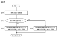
- FIG. 14 is a flow chart showing yet another example of the subroutine of step S11 in FIG. 8.
- step S71 the inclination of the vehicle 1 is obtained from the acceleration sensor 61, and in the following step S72, it is determined whether the inclination of the vehicle 1 is equal to or greater than a predetermined value. If it is determined that the inclination of the vehicle 1 is equal to or greater than the predetermined value, the process proceeds to step S23, and if it is determined that the inclination of the vehicle 1 is less than the predetermined value, the process proceeds to step S24.
- FIG. 15 is a flow chart showing yet another example of the subroutine of step S11 in FIG. 8.
- step S81 when the brakes are applied, the rotation speed of the wheels of the vehicle 1 is obtained, and in step S82, it is determined whether any of the wheels are rotating. If it is determined that any of the wheels are rotating, the process proceeds to step S23, and if it is determined that none of the wheels are rotating, the process proceeds to step S24.
- the braking control device 50 of an electric parking brake 80 includes a first actuator for actuating a first brake of at least one of the left front wheel 11 and the left rear wheel 12 of the vehicle 1 with a first braking force, and a second actuator for actuating a second brake of at least one of the right front wheel 21 and the right rear wheel 22 of the vehicle 1 with a second braking force
- the vehicle 1 has a detection means for detecting the inclination of the vehicle 1
- the braking control device 50 determines whether the inclination detected by the detection means is less than a predetermined value when the vehicle 1 is parked, and when it is determined that the inclination is less than the predetermined value, controls the first actuator and the second actuator so that one of the first braking force and the second braking force is smaller than the other.
- the braking control device 50 determines that the inclination is less than the predetermined value, it stops one of the first actuator and the second actuator. This makes it possible to further prevent the life of the actuator that operates the brakes from being shortened.
- the braking control device 50 when at least one of the first actuator and the second actuator is actuated, stores the set first braking force and the second braking force in correspondence with each other, and when it determines that the slope is less than the predetermined value, it acquires the previous first braking force and the second braking force that were set the last time at least one of the first actuator and the second actuator was actuated, and when the previous first braking force is greater than the previous second braking force, it sets the first braking force smaller than the second braking force, and when the previous first braking force is smaller than the previous second braking force, it sets the first braking force larger than the second braking force. This makes it possible to prevent the number of times one of the first actuator and the second actuator is actuated from increasing.
- the braking control device 50 determines whether the vehicle 1 is loaded onto a transporter that transports the vehicle 1, and if it determines that the vehicle 1 is loaded onto the transporter, it activates the first actuator and the second actuator, and sets the first braking force and the second braking force so that the difference between the first braking force and the second braking force is equal to or less than a predetermined braking force. This makes it possible to prevent the vehicle 1 loaded onto the transporter from moving on the transporter.
- the braking control device 50 determines whether the vehicle 1 is in a state in which at least one of the first braking force and the second braking force is reduced, and if it determines that the vehicle 1 is in the state in which at least one of the first braking force and the second braking force is reduced, it operates the first actuator and the second actuator, and executes parking control to set the first braking force and the second braking force so that the difference between the first braking force and the second braking force is less than a predetermined braking force.
- the braking control device 50 estimates the temperature of the brake pads of the first brake and the second brake, determines whether the estimated temperature is equal to or higher than the fade temperature, and executes the parking control if it is determined that the estimated temperature is equal to or higher than the fade temperature. This makes it possible to appropriately stop the movement of the vehicle 1 even when the temperature of the brake pads is relatively high.
- the braking control device 50 acquires the brake fluid pressure of the first brake and the second brake when at least one of the first brake and the second brake is activated, and the deceleration of the vehicle 1, acquires the deceleration corresponding to the pressure from a preset relationship between the pressure and the deceleration, determines whether the actual deceleration is lower than the deceleration corresponding to the pressure by a predetermined deceleration or more, and executes the parking control if it is determined that the actual deceleration is lower than the deceleration corresponding to the pressure by the predetermined deceleration or more.
- the movement of the vehicle 1 can be appropriately restrained even if the original braking force corresponding to the brake fluid pressure cannot be obtained.
- the braking control device 50 determines whether the outside air temperature of the vehicle 1 is equal to or lower than a predetermined temperature, and executes the parking control if it determines that the outside air temperature is equal to or lower than the predetermined temperature. This makes it possible to appropriately stop the movement of the vehicle 1 even if the operating efficiency of the actuator decreases.
- the braking control device 50 determines whether the wipers of the vehicle 1 are operating, and executes the parking control if it is determined that the wipers are operating. This makes it possible to appropriately stop the movement of the vehicle 1 even in conditions where the vehicle 1 is slippery, such as during rainy weather or snowfall.
- the braking control device 50 determines whether the acceleration of the vehicle 1 is equal to or greater than a predetermined acceleration, and executes the parking control if it determines that the acceleration is equal to or greater than the predetermined acceleration. This makes it possible to appropriately stop the movement of the vehicle 1 even if another object comes into contact with the vehicle 1.
- the braking control device 50 determines whether the inclination is equal to or greater than the predetermined value, and executes the parking control if it determines that the inclination is equal to or greater than the predetermined value. This makes it possible to appropriately stop the movement of the vehicle 1 even if the inclination of the vehicle 1 changes.
- the braking control device 50 determines whether at least one of the left front wheel 11, the left rear wheel 12, the right front wheel 21, and the right rear wheel 22 is rotating, and executes the parking control when it determines that at least one of the left front wheel 11, the left rear wheel 12, the right front wheel 21, and the right rear wheel 22 is rotating.
- the second control is quickly started, and the movement of the vehicle 1 can be appropriately stopped.
- a brake control device 50 for an electric parking brake 80 including a first actuator that operates a first brake of at least one of the left front wheel 11 and the left rear wheel 12 of the vehicle 1 with a first braking force, and a second actuator that operates a second brake of at least one of the right front wheel 21 and the right rear wheel 22 of the vehicle 1 with a second braking force, in which the vehicle 1 has a detection means for detecting the inclination of the vehicle 1, a determination unit 51 that determines whether the inclination detected by the detection means is less than a predetermined value when the vehicle 1 is parked, and a control unit 52 that controls the first actuator and the second actuator so that one of the first braking force and the second braking force is smaller than the other when the determination unit 51 determines that the inclination is less than the predetermined value.
Landscapes
- Engineering & Computer Science (AREA)
- Transportation (AREA)
- Mechanical Engineering (AREA)
- Regulating Braking Force (AREA)
Priority Applications (2)
| Application Number | Priority Date | Filing Date | Title |
|---|---|---|---|
| JP2025516448A JPWO2024224600A1 (https=) | 2023-04-28 | 2023-04-28 | |
| PCT/JP2023/016855 WO2024224600A1 (ja) | 2023-04-28 | 2023-04-28 | 制動制御方法及び制動制御装置 |
Applications Claiming Priority (1)
| Application Number | Priority Date | Filing Date | Title |
|---|---|---|---|
| PCT/JP2023/016855 WO2024224600A1 (ja) | 2023-04-28 | 2023-04-28 | 制動制御方法及び制動制御装置 |
Publications (1)
| Publication Number | Publication Date |
|---|---|
| WO2024224600A1 true WO2024224600A1 (ja) | 2024-10-31 |
Family
ID=93256227
Family Applications (1)
| Application Number | Title | Priority Date | Filing Date |
|---|---|---|---|
| PCT/JP2023/016855 Ceased WO2024224600A1 (ja) | 2023-04-28 | 2023-04-28 | 制動制御方法及び制動制御装置 |
Country Status (2)
| Country | Link |
|---|---|
| JP (1) | JPWO2024224600A1 (https=) |
| WO (1) | WO2024224600A1 (https=) |
Cited By (1)
| Publication number | Priority date | Publication date | Assignee | Title |
|---|---|---|---|---|
| US20240391446A1 (en) * | 2023-05-26 | 2024-11-28 | ZF Active Safety US Inc. | Rotor condition monitoring system and method |
Citations (3)
| Publication number | Priority date | Publication date | Assignee | Title |
|---|---|---|---|---|
| JP2003327099A (ja) * | 2002-05-13 | 2003-11-19 | Honda Motor Co Ltd | 電動駐車ブレーキ装置 |
| JP2008111503A (ja) * | 2006-10-31 | 2008-05-15 | Advics:Kk | 駐車ブレーキ制御装置 |
| JP2019189109A (ja) * | 2018-04-26 | 2019-10-31 | トヨタ自動車株式会社 | 車両の制動制御装置 |
-
2023
- 2023-04-28 JP JP2025516448A patent/JPWO2024224600A1/ja active Pending
- 2023-04-28 WO PCT/JP2023/016855 patent/WO2024224600A1/ja not_active Ceased
Patent Citations (3)
| Publication number | Priority date | Publication date | Assignee | Title |
|---|---|---|---|---|
| JP2003327099A (ja) * | 2002-05-13 | 2003-11-19 | Honda Motor Co Ltd | 電動駐車ブレーキ装置 |
| JP2008111503A (ja) * | 2006-10-31 | 2008-05-15 | Advics:Kk | 駐車ブレーキ制御装置 |
| JP2019189109A (ja) * | 2018-04-26 | 2019-10-31 | トヨタ自動車株式会社 | 車両の制動制御装置 |
Cited By (2)
| Publication number | Priority date | Publication date | Assignee | Title |
|---|---|---|---|---|
| US20240391446A1 (en) * | 2023-05-26 | 2024-11-28 | ZF Active Safety US Inc. | Rotor condition monitoring system and method |
| US12459482B2 (en) * | 2023-05-26 | 2025-11-04 | ZF Active Safety US Inc. | Rotor condition monitoring system and method |
Also Published As
| Publication number | Publication date |
|---|---|
| JPWO2024224600A1 (https=) | 2024-10-31 |
Similar Documents
| Publication | Publication Date | Title |
|---|---|---|
| US6496768B2 (en) | Vehicular brake control apparatus and control method therefor | |
| JP2022068844A (ja) | 大型車両の車輪スリップベースの車両モーション管理 | |
| US9132819B2 (en) | Vehicle control apparatus | |
| CN113646193B (zh) | 用于优化车辆的制动和加速的经由主动悬架进行的滑移控制 | |
| US20160214595A1 (en) | Driver Assistance System with Increased Reliability and Availability | |
| CN110949508B (zh) | 四轮转向车辆 | |
| CN114746315B (zh) | 电子驻车制动系统及其控制方法 | |
| US20040140710A1 (en) | Apparatus and method for controlling an electric park brake | |
| CN110494332A (zh) | 用于机动车的制动调节系统 | |
| US11590943B2 (en) | Control system of brake-by-wire device | |
| WO2024224600A1 (ja) | 制動制御方法及び制動制御装置 | |
| CN105922977B (zh) | 车辆的制动装置及其制动方法 | |
| US20240116481A1 (en) | Method of operating a motor vehicle | |
| US12084019B2 (en) | Electronic parking brake system and method for controlling clamping force thereof | |
| JP7588252B2 (ja) | 車両制御装置および車両制御方法 | |
| US11273823B2 (en) | Method for determining a maximum speed of a vehicle during a parking maneuver | |
| CN110139786A (zh) | 用于对表示车辆驻车制动的力进行控制的方法及其系统 | |
| CN115534913B (zh) | 控制车辆驻车的方法、电子驻车制动器、驻车系统和车辆 | |
| JPWO2020035748A1 (ja) | モータサイクルの挙動を制御する制御装置及び制御方法 | |
| JP2003104195A (ja) | 電動ブレーキ装置 | |
| JP2020050004A (ja) | 電動パーキングブレーキシステム | |
| JP2000203402A (ja) | 制動制御装置 | |
| JP5176166B2 (ja) | ディスクブレーキ装置 | |
| JPWO2024224600A5 (https=) | ||
| JP2003063376A (ja) | 電動ブレーキ装置 |
Legal Events
| Date | Code | Title | Description |
|---|---|---|---|
| 121 | Ep: the epo has been informed by wipo that ep was designated in this application |
Ref document number: 23935376 Country of ref document: EP Kind code of ref document: A1 |
|
| WWE | Wipo information: entry into national phase |
Ref document number: 2025516448 Country of ref document: JP |
|
| NENP | Non-entry into the national phase |
Ref country code: DE |