WO2024219176A1 - 超音波探傷装置、および、超音波探傷方法 - Google Patents
超音波探傷装置、および、超音波探傷方法 Download PDFInfo
- Publication number
- WO2024219176A1 WO2024219176A1 PCT/JP2024/012357 JP2024012357W WO2024219176A1 WO 2024219176 A1 WO2024219176 A1 WO 2024219176A1 JP 2024012357 W JP2024012357 W JP 2024012357W WO 2024219176 A1 WO2024219176 A1 WO 2024219176A1
- Authority
- WO
- WIPO (PCT)
- Prior art keywords
- temperature
- delay material
- flaw detection
- test object
- ultrasonic flaw
- Prior art date
- Legal status (The legal status is an assumption and is not a legal conclusion. Google has not performed a legal analysis and makes no representation as to the accuracy of the status listed.)
- Ceased
Links
Images

Classifications
-
- G—PHYSICS
- G01—MEASURING; TESTING
- G01N—INVESTIGATING OR ANALYSING MATERIALS BY DETERMINING THEIR CHEMICAL OR PHYSICAL PROPERTIES
- G01N29/00—Investigating or analysing materials by the use of ultrasonic, sonic or infrasonic waves; Visualisation of the interior of objects by transmitting ultrasonic or sonic waves through the object
- G01N29/22—Details, e.g. general constructional or apparatus details
- G01N29/24—Probes
-
- G—PHYSICS
- G01—MEASURING; TESTING
- G01N—INVESTIGATING OR ANALYSING MATERIALS BY DETERMINING THEIR CHEMICAL OR PHYSICAL PROPERTIES
- G01N29/00—Investigating or analysing materials by the use of ultrasonic, sonic or infrasonic waves; Visualisation of the interior of objects by transmitting ultrasonic or sonic waves through the object
- G01N29/22—Details, e.g. general constructional or apparatus details
- G01N29/26—Arrangements for orientation or scanning by relative movement of the head and the sensor
-
- G—PHYSICS
- G01—MEASURING; TESTING
- G01N—INVESTIGATING OR ANALYSING MATERIALS BY DETERMINING THEIR CHEMICAL OR PHYSICAL PROPERTIES
- G01N29/00—Investigating or analysing materials by the use of ultrasonic, sonic or infrasonic waves; Visualisation of the interior of objects by transmitting ultrasonic or sonic waves through the object
- G01N29/22—Details, e.g. general constructional or apparatus details
- G01N29/32—Arrangements for suppressing undesired influences, e.g. temperature or pressure variations, compensating for signal noise
Definitions
- This disclosure relates to an ultrasonic flaw detection device and an ultrasonic flaw detection method.
- This application claims the benefit of priority based on Japanese Patent Application No. 2023-66959, filed on April 17, 2023, the contents of which are incorporated herein by reference.
- One of the ultrasonic flaw detection methods using ultrasonic flaw detectors is the angle beam method, in which ultrasonic waves are incident on the test object at an angle.
- the angle beam method a delay material is placed between the probe and the test object, and the ultrasonic waves transmitted from the probe are refracted at the interface between the delay material and the test object, irradiating the ultrasonic waves at a target position inside the test object.
- the target position inside the test object may be referred to as the "target position.”
- the propagation speed of the ultrasonic waves in the test object changes, and the refraction angle of the ultrasonic waves at the interface between the delay material and the test object changes. For this reason, when testing a test object whose temperature changes, depending on the temperature of the test object, there is a problem that the ultrasonic waves may not be irradiated to the target position, making it impossible to test the target position.
- Patent Document 1 which has a mechanism for changing the installation angle of the probe, has the problem that the device becomes large.
- the present disclosure aims to provide an ultrasonic flaw detection device and an ultrasonic flaw detection method that are capable of inspecting a target position with a simple configuration.
- an ultrasonic flaw detection device includes a probe that transmits ultrasonic waves into the interior of the object to be inspected and receives ultrasonic waves reflected from within the object to be inspected, a delay material disposed between the probe and the object to be inspected, a temperature adjustment mechanism that adjusts the temperature of the delay material, a first temperature detection unit that detects the temperature of the object to be inspected, and a control unit that controls the temperature adjustment mechanism based on the temperature of the object to be inspected detected by the first temperature detection unit.
- the control unit may also refer to test object sound speed information indicating the relationship between the test object's sound speed and temperature, and delay material sound speed information indicating the relationship between the delay material's sound speed and temperature, and control the temperature adjustment mechanism based on the test object's temperature detected by the first temperature detection unit.
- the control unit may also refer to the test object sound speed information, calculate the test object sound speed from the temperature of the test object detected by the first temperature detection unit, calculate the delay material sound speed based on the test object sound speed, refer to the delay material sound speed information, calculate the delay material target temperature from the delay material sound speed, and control the temperature adjustment mechanism based on the target temperature.
- the ultrasonic flaw detector may also include a storage unit that prestores the test object sound velocity information and delay material sound velocity information.
- the ultrasonic flaw detection device may also include a second temperature detection unit that detects the temperature of the delay material, and the control unit may perform feedback control of the temperature adjustment mechanism based on the temperature of the delay material detected by the second temperature detection unit.
- an ultrasonic inspection method detects the temperature of an object to be inspected, transmits ultrasonic waves into the inside of the object to be inspected, and adjusts the temperature of a delay material disposed between the object to be inspected and a probe that receives ultrasonic waves reflected from inside the object to be inspected, based on the detected temperature of the object to be inspected.
- FIG. 1 is a schematic diagram showing a schematic configuration of an ultrasonic flaw detection device according to the present embodiment.
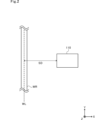
- FIG. 2 is a diagram for explaining the movement direction of a probe constituting the ultrasonic flaw detection device according to this embodiment.
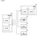
- FIG. 3 is a block diagram showing an example of the functional configuration of the ultrasonic flaw detection device according to the present embodiment.
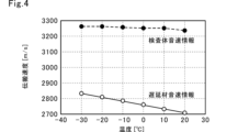
- FIG. 4 is a diagram illustrating an example of test object sound velocity information and delay line temperature information according to the present embodiment.
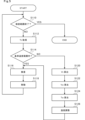
- FIG. 5 is a flowchart showing a process flow of the ultrasonic flaw detection method according to the present embodiment.
- Fig. 1 is a schematic diagram showing a schematic configuration of an ultrasonic flaw detection device 100 according to the present embodiment.
- Fig. 2 is a diagram explaining a moving direction of a probe 110 constituting the ultrasonic flaw detection device 100 according to the present embodiment.
- the X-axis, Y-axis, and Z-axis that intersect perpendicularly are defined as shown in Fig. 1 and Fig. 2.
- the dashed lines indicate the direction of the ultrasonic wave transmitted from the ultrasonic flaw detector 100.
- the dashed line indicates a normal (perpendicular) line to the interface IF between the delay material 130 and the test object T.
- the dashed line indicates a weld line WL of the welded portion WR. show.
- the ultrasonic flaw detection device 100 uses ultrasonic waves to inspect an object to be inspected T.
- the object to be inspected T has regions with different temperatures. For example, the temperature of the object to be inspected T increases from the bottom to the top.
- the ultrasonic flaw detection device 100 inspects, for example, a welded portion WR provided on an inspection object T having regions with different temperatures.
- the welded portion WR extends, for example, in the Y-axis direction in Figures 1 and 2.
- the locus of the center of the welded portion WR in the X-axis direction in Figure 1, that is, a virtual line extending in the Y-axis direction in Figure 1 that passes through the center of the welded portion WR in the X-axis direction in Figure 1, is defined as the weld line WL of the welded portion WR.
- the ultrasonic flaw detection device 100 includes a probe 110 and a control device 210.
- the probe 110 includes a probe 120, a delay material 130, a temperature adjustment mechanism 140, a first temperature detection unit 150, and a second temperature detection unit 152.
- the probe 110 is moved along the weld line WL of the welded portion WR by a moving mechanism (not shown). That is, the probe 110 is moved in the Y-axis direction in FIGS. 1 and 2 by the moving mechanism. The probe 110 is also moved so that the shortest distance between the weld line WL of the welded portion WR and the probe 110 is maintained at a predetermined set distance SD.
- the set distance SD will be described later.
- the probe 120 transmits ultrasonic waves into the interior of the test object T and receives ultrasonic waves reflected from within the test object T.
- the probe 120 includes, for example, a transmitting section 122 having a transducer that transmits ultrasonic waves, and a receiving section 124 having a transducer that receives ultrasonic waves (see FIG. 3).
- the delay material 130 is disposed between the probe 120 and the object to be inspected T.
- the delay material 130 is in contact with the probe 120 and the object to be inspected T.
- the delay material 130 holds (fixes) the probe 120 so that the incident angle ⁇ i of the ultrasound transmitted by the probe 120 at the reference temperature is a predetermined incident angle ⁇ I.
- the reference temperature is, for example, room temperature (25°C).
- the incident angle ⁇ i is the angle between the propagation direction of the ultrasound in the delay material 130 and the normal (perpendicular line) to the interface IF between the delay material 130 and the test object T.
- the incident angle ⁇ i changes depending on the temperature of the delay material 130.
- the delay material 130 propagates the ultrasonic waves transmitted from the probe 120 and causes them to enter the object to be inspected T.
- the speed of sound (propagation speed) of the ultrasonic waves in the delay material 130 is different from the speed of sound (propagation speed) of the ultrasonic waves in the object to be inspected T. Therefore, the ultrasonic waves transmitted from the probe 120 and propagating through the delay material 130 are refracted at a predetermined refraction angle ⁇ r at the interface IF between the delay material 130 and the object to be inspected T.
- the refraction angle ⁇ r is the angle between the normal (perpendicular line) to the interface IF between the delay material 130 and the object to be inspected T and the propagation direction of the ultrasonic waves in the object to be inspected T.
- the refraction angle ⁇ r changes depending on the temperature of the object to be inspected T.
- the probe 120 and the delay material 130 are installed on the inspection object T so that when the temperature of the inspection object T is the reference temperature, the ultrasonic waves transmitted from the probe 120 propagate to the target position P inside the inspection object T.
- the target position P is, for example, a position on the weld line WL of the welded part WR.
- the distance between the probe 110 (probe 120 and delay material 130) and the welded part WR at which the ultrasonic waves transmitted from the probe 120 propagate to the target position P is the set distance SD.
- the set distance SD is determined based on the incident angle ⁇ I at the reference temperature, the refraction angle ⁇ R at the reference temperature, and the target position P.
- the incident angle ⁇ I and the refraction angle ⁇ R are set in advance by experiments, simulations, etc.
- the material constituting the delay material 130 is appropriately determined depending on the material constituting the test object T.
- the sound speed of the material constituting the delay material 130 only needs to be different from the sound speed of the material constituting the test object T.
- the delay material 130 is made of, for example, a resin such as acrylic or polystyrene, glass, or metal.
- the temperature adjustment mechanism 140 adjusts the temperature of the delay material 130.
- the temperature adjustment mechanism 140 adjusts the temperature of the delay material 130, for example, when the temperature of the test object T is not within the reference temperature range.
- the reference temperature range is a temperature range that includes the reference temperature.
- the reference temperature range is, for example, a range of the reference temperature ⁇ 25°C.
- the temperature adjustment mechanism 140 has, for example, either one or both of a mechanism for heating the delay material 130 and a mechanism for cooling the delay material 130.
- the mechanism for heating the delay material 130 is, for example, an electric heater.
- the mechanism for cooling the delay material 130 is, for example, a Peltier element cooler.
- the temperature adjustment mechanism 140 is provided, for example, on the outer periphery of the delay material 130.
- the temperature adjustment mechanism 140 is provided in the delay material 130 so as not to block the ultrasonic waves transmitted by the probe 120 and the ultrasonic waves received by the probe 120.
- the temperature adjustment mechanism 140 may also be, for example, a mechanism for circulating a heat medium through the delay material 130.
- a passage through which the heat medium passes is formed within the delay material 130, and the temperature adjustment mechanism 140 may adjust the temperature of the delay material 130 by flowing the heat medium through the passage.
- the first temperature detection unit 150 detects the temperature of the test object T.
- the first temperature detection unit 150 is, for example, a temperature sensor.
- the second temperature detection unit 152 detects the temperature of the delay material 130.
- the second temperature detection unit 152 is, for example, a temperature sensor.
- the control device 210 manages and controls the ultrasonic flaw detection device 100.
- FIG. 3 is a block diagram showing an example of the functional configuration of the ultrasonic flaw detection device 100 according to this embodiment. In FIG. 3, the dashed arrows indicate the flow of signals. As shown in FIG. 3, the control device 210 includes a control unit 212 and a memory unit 214.
- the control unit 212 is composed of a semiconductor integrated circuit including a CPU (central processing unit).
- the control unit 212 reads out programs and parameters for operating the CPU from the ROM.
- the control unit 212 manages and controls the entire ultrasonic flaw detection device 100 in cooperation with the RAM as a work area and other electronic circuits.
- the control unit 212 controls the transmission unit 122 of the probe 120 to transmit ultrasonic waves from the transmission unit 122.
- the control unit 212 also analyzes the ultrasonic waves received by the reception unit 124 to detect the presence or absence of defects at the target position P and in the vicinity of the target position P.
- the control unit 212 also acquires the temperature of the test object T from the first temperature detection unit 150, and acquires the temperature of the delay material 130 from the second temperature detection unit 152.
- the control unit 212 controls the temperature adjustment mechanism 140 based on the acquired temperatures of the test object T and the delay material 130.
- the storage unit 214 is composed of a ROM, a RAM, a flash memory, a HDD, etc.
- the storage unit 214 stores programs and various data used by the control unit 212.
- the storage unit 214 stores, for example, test object sound speed information and delay material sound speed information in advance.
- the test object sound speed information is information that indicates the relationship between the test object's sound speed and temperature.
- the delay material temperature information is information that indicates the relationship between the sound speed and temperature of the delay material 130.
- FIG. 4 is a diagram illustrating an example of inspection object sound speed information and delay material temperature information according to this embodiment.
- the vertical axis indicates the propagation speed (sound speed) [m/s].
- the horizontal axis indicates temperature [°C].
- the inspection object sound speed information is taken as an example when the inspection object T is steel
- the delay material temperature information is taken as an example when the delay material 130 is acrylic.
- the sound velocity of the ultrasonic wave in the test object T is 3265 m/s when the temperature of the test object T is -30°C, 3265 m/s when the temperature of the test object T is -20°C, 3256 m/s when the temperature of the test object T is -10°C, 3252 m/s when the temperature of the test object T is 0°C, 3252 m/s when the temperature of the test object T is 10°C, and 3230 m/s when the temperature of the test object T is 20°C.
- the sound speed of the ultrasonic wave in the delay material 130 is 2833 m/s when the temperature of the delay material 130 is -30°C, 2810 m/s when the temperature of the delay material 130 is -20°C, 2788 m/s when the temperature of the delay material 130 is -10°C, 2762 m/s when the temperature of the delay material 130 is 0°C, 2733 m/s when the temperature of the delay material 130 is 10°C, and 2710 m/s when the temperature of the delay material 130 is 20°C.
- Fig. 5 is a flowchart showing the flow of processing of the ultrasonic inspection method according to this embodiment.
- the ultrasonic inspection method according to this embodiment includes an end determination process S110, a temperature acquisition process S112, a temperature determination process S114, an inspection process S116, a movement process S118, an inspection object sound speed calculation process S120, a delay material sound speed calculation process S122, a delay material temperature calculation process S124, and a temperature adjustment process S126.
- an end determination process S110 a temperature acquisition process S112, a temperature determination process S114, an inspection process S116, a movement process S118, an inspection object sound speed calculation process S120, a delay material sound speed calculation process S122, a delay material temperature calculation process S124, and a temperature adjustment process S126.
- End determination process S110 The control unit 212 judges whether or not the inspection of the predetermined inspection range has been completed. As a result, when it is judged that the inspection of the inspection range has not been completed (NO in S110), the control unit 212 shifts the process to a temperature acquisition process S112. On the other hand, when it is judged that the inspection of the inspection range has been completed (YES in S110), the control unit 212 ends the ultrasonic flaw detection method.
- the control unit 212 acquires the temperature Tt of the test object T detected by the first temperature detection unit 150. Then, the control unit 212 advances the process to a temperature determination process S114.
- the control unit 212 judges whether or not the temperature Tt of the inspection object T acquired in the temperature acquisition process S112 is within a reference temperature range. As a result, when it is judged that the temperature Tt is within the reference temperature range (YES in S114), the control unit 212 shifts the process to the inspection process S116. On the other hand, when it is judged that the temperature Tt is not within the reference temperature range (NO in S114), the control unit 212 shifts the process to the inspection object sound speed calculation process S120.
- the control unit 212 controls the transmission unit 122 of the probe 120 to transmit ultrasonic waves from the transmission unit 122.
- the control unit 212 also analyzes the ultrasonic waves received by the reception unit 124 to detect the presence or absence of defects at the target position P and in the vicinity of the target position P. Then, the control unit 212 shifts the process to a movement process S118.
- the moving mechanism (not shown) moves the probe 110 from the first position where the inspection process S116 was executed this time to the second position.
- the second position is a position different from the first position, and is a position where the shortest distance between the weld line WL of the welded part WR and the probe 110 is the set distance SD. Then, the control unit 212 returns the process to the end determination process S110.
- the control unit 212 refers to the inspection object sound velocity information stored in the memory unit 214, and calculates the sound velocity Vt of the inspection object T when the temperature Tt of the inspection object T acquired in the temperature acquisition process S112 is the inspection object T. Then, the control unit 212 shifts the process to the delay material sound velocity calculation process S122.
- the control unit 212 calculates the sound speed Vw of the delay material 130 using the following formula (1).
- Vw Vt ⁇ sin ⁇ I / sin ⁇ R...Formula (1)
- Vw is the sound velocity of the delay material 130
- Vt is the sound velocity of the test object T.
- ⁇ I is the incident angle ⁇ i at the reference temperature (see FIG. 1)
- ⁇ R is the refraction angle ⁇ r at the reference temperature (see FIG. 1).
- the incident angle ⁇ I and the refraction angle ⁇ R are set in advance by experiments, simulations, etc.
- the control unit 212 advances the process to a delay material temperature calculation process S124.
- the control unit 212 refers to the delay material sound speed information stored in the memory unit 214 and calculates the temperature of the delay material 130 when the sound speed Vw of the delay material 130 calculated in the delay material sound speed calculation process S122 is the target temperature Tw. Then, the control unit 212 shifts the process to the temperature adjustment process S126.
- the control unit 212 performs feedback control on the temperature adjustment mechanism 140 so that the temperature of the delay material 130 detected by the second temperature detection unit 152 becomes the target temperature Tw calculated by the delay material temperature calculation process S124. Then, when the temperature of the delay material 130 detected by the second temperature detection unit 152 becomes the target temperature Tw calculated by the delay material temperature calculation process S124, the control unit 212 shifts the process to the inspection process S116.
- the ultrasonic flaw detection device 100 is equipped with a temperature adjustment mechanism 140 that adjusts the temperature of the delay material 130, and controls the temperature adjustment mechanism 140 based on the test object sound speed information, the delay material sound speed information, and the temperature Tt of the test object T.
- the sound speed Vt of the ultrasonic wave in the test object T changes from the sound speed Vt at the reference temperature, and the refraction angle ⁇ r becomes different from the refraction angle ⁇ R at the reference temperature.
- the ultrasonic wave will be irradiated at a position different from the target position P, and the target position P cannot be inspected.
- the ultrasonic wave can be irradiated to the target position P, but the propagation distance of the ultrasonic wave from the probe 120 to the target position P will change. This causes a problem in that the degree of attenuation of the ultrasonic wave changes, reducing the inspection accuracy.
- the mounting angle of the probe was changed or multiple delay materials with different sound speeds were used depending on the temperature Tt of the test object T.
- the conventional technology that includes a mechanism for changing the mounting angle of the probe has the problem that the equipment becomes large.
- the conventional technology that uses multiple delay materials has the problem that the operator is forced to carry out the cumbersome task of replacing the delay materials.
- the ultrasonic flaw detection device 100 controls the temperature adjustment mechanism 140 based on the temperature Tt of the test object T to adjust the temperature of the delay material 130, change the sound speed Vw of the delay material 130, and change the incident angle ⁇ i to propagate the ultrasonic waves transmitted by the probe 120 to the target position P.
- the ultrasonic flaw detection device 100 according to the present embodiment can perform inspection of the target position P while maintaining the installation position of the probe 110 at the set distance SD, even if the temperature of the test object T changes, with a simple configuration that only changes the temperature of the delay material 130.
- the ultrasonic flaw detection device 100 can avoid changes in the degree of attenuation of the ultrasonic waves and prevent a decrease in inspection accuracy.
- the ultrasonic flaw detection device 100 according to the present embodiment can perform inspection of the target position P by simply adjusting the temperature of the delay material 130, making it possible to omit the effort of preparing multiple delay materials with different sound speeds and replacing the delay materials.
- the ultrasonic flaw detection device 100 also includes a second temperature detection unit 152 that detects the temperature of the delay material 130, and the control unit 212 performs feedback control on the temperature adjustment mechanism 140 based on the temperature of the delay material 130 detected by the second temperature detection unit 152.
- This allows the ultrasonic flaw detection device 100 according to this embodiment to set the temperature of the delay material 130 to the target temperature Tw of the delay material 130 associated with the delay material sound speed information. Therefore, the ultrasonic flaw detection device 100 according to this embodiment is capable of propagating the ultrasonic waves transmitted by the probe 120 to the target position P with high accuracy.
- the second temperature detection unit 152 of the ultrasonic flaw detection device 100 is a temperature sensor.
- the second temperature detection unit 152 is not limited in configuration as long as it can detect the temperature of the delay material 130.
- the second temperature detection unit 152 may be a probe different from the probe 120, which has a transmitting unit having a transducer for transmitting ultrasonic waves and a receiving unit having a transducer for receiving ultrasonic waves.
- the second temperature detection unit 152 is provided in the delay material 130, and the transmitting unit of the second temperature detection unit 152 transmits ultrasonic waves perpendicularly to the interface IF between the delay material 130 and the test object T.
- the second temperature detection unit 152 calculates the sound speed Vw of the delay material 130 based on the time from transmitting the ultrasonic waves to receiving the ultrasonic waves reflected at the interface IF and the thickness of the delay material 130 (the length in the Z-axis direction in FIG. 1), and calculates the temperature of the delay material 130 based on the sound speed Vw.
- the control unit 212 performs feedback control on the temperature adjustment mechanism 140 so that the temperature of the delay material 130 detected by the second temperature detection unit 152 becomes the target temperature Tw calculated by the delay material temperature calculation process S124.
- the control unit 212 may control the temperature adjustment mechanism 140 so that the temperature of the delay material 130 becomes within a target temperature range that includes the target temperature Tw.
- the target temperature range is a temperature range that includes the target temperature Tw.
- the target temperature range is, for example, a range of the target temperature Tw ⁇ 25°C.
- the ultrasonic inspection device 100 is provided with the second temperature detection unit 152.
- the control unit 212 may refer to the inspection object sound velocity information and the delay material sound velocity information, and perform open control on the temperature adjustment mechanism 140 based on the temperature Tt of the inspection object T detected by the first temperature detection unit 150.
- the control unit 212 may, for example, start the operation of the temperature adjustment mechanism 140 in the temperature adjustment process S126, adjust the temperature adjustment capacity of the temperature adjustment mechanism 140, and after a predetermined fixed time has elapsed, transfer the process to the inspection process S116.
- the fixed time is the time from when the operation of the temperature adjustment mechanism 140 starts until the target temperature Tw is reached, and is determined in advance.
- the control unit 212 may start the operation of the temperature adjustment mechanism 140 in the temperature adjustment process S126, and after a predetermined fluctuation time has elapsed, the process may proceed to the inspection process S116 while keeping the temperature adjustment capacity of the temperature adjustment mechanism 140 constant.
- the fluctuation time is determined in advance based on the time it takes to reach the target temperature Tw according to the constant temperature adjustment capacity of the temperature adjustment mechanism 140.
- the memory unit 214 of the control device 210 stores the inspection object sound velocity information and the delay material sound velocity information in advance.
- the memory unit 214 of the control device 210 does not have to store the inspection object sound velocity information and the delay material sound velocity information.
- the control device 210 may control the temperature adjustment mechanism 140 based on the target temperature Tw of the delay material 130 acquired in response to an operation input by an operator to an operation unit (not shown). In this case, the operator may calculate the target temperature Tw based on the temperature Tt of the inspection object T detected by the first temperature detection unit 150.
- control unit 212 refers to the test object sound speed information and the delay material sound speed information, and controls the temperature adjustment mechanism 140 based on the temperature of the test object T detected by the first temperature detection unit 150.
- control unit 212 may control the temperature adjustment mechanism 140 based on the temperature of the test object T detected by the first temperature detection unit 150 without referring to the test object sound speed information and the delay material sound speed information.
- control unit 212 may operate the temperature adjustment mechanism 140 when the temperature of the test object T detected by the first temperature detection unit 150 is different from the reference temperature.
- the probe 120 may also be disposed inside the delay material 130.
- the probe 120 may also be an array probe including a transmitting section having multiple transducers and a receiving section having multiple transducers. This allows the target position P to be suitably inspected even when there is a large change in temperature of the inspection object T.
- the ultrasonic flaw detection device 100 controls the temperature adjustment mechanism 140 so that ultrasonic waves are transmitted to the target position P.
- the ultrasonic flaw detection device 100 may control the temperature adjustment mechanism 140 to change the transmission position of ultrasonic waves. This allows the ultrasonic flaw detection device 100 to inspect various locations by simply controlling the temperature adjustment mechanism 140 without changing the installation position.
- the ultrasonic flaw detection device 100 can scan and inspect the weld line WL of the welded portion WR by simply controlling the temperature adjustment mechanism 140 without changing the installation position.
- This disclosure can contribute, for example, to Goal 12 of the Sustainable Development Goals (SDGs), "Ensure sustainable consumption and production patterns.”
Landscapes
- Physics & Mathematics (AREA)
- Health & Medical Sciences (AREA)
- Life Sciences & Earth Sciences (AREA)
- Chemical & Material Sciences (AREA)
- Analytical Chemistry (AREA)
- Biochemistry (AREA)
- General Health & Medical Sciences (AREA)
- General Physics & Mathematics (AREA)
- Immunology (AREA)
- Pathology (AREA)
- Investigating Or Analyzing Materials By The Use Of Ultrasonic Waves (AREA)
Priority Applications (2)
| Application Number | Priority Date | Filing Date | Title |
|---|---|---|---|
| JP2024540675A JP7718597B2 (ja) | 2023-04-17 | 2024-03-27 | 超音波探傷装置、および、超音波探傷方法 |
| AU2024258412A AU2024258412A1 (en) | 2023-04-17 | 2024-03-27 | Ultrasonic flaw detection device and ultrasonic flaw detection method |
Applications Claiming Priority (2)
| Application Number | Priority Date | Filing Date | Title |
|---|---|---|---|
| JP2023066959 | 2023-04-17 | ||
| JP2023-066959 | 2023-04-17 |
Publications (1)
| Publication Number | Publication Date |
|---|---|
| WO2024219176A1 true WO2024219176A1 (ja) | 2024-10-24 |
Family
ID=93152660
Family Applications (1)
| Application Number | Title | Priority Date | Filing Date |
|---|---|---|---|
| PCT/JP2024/012357 Ceased WO2024219176A1 (ja) | 2023-04-17 | 2024-03-27 | 超音波探傷装置、および、超音波探傷方法 |
Country Status (3)
| Country | Link |
|---|---|
| JP (1) | JP7718597B2 (https=) |
| AU (1) | AU2024258412A1 (https=) |
| WO (1) | WO2024219176A1 (https=) |
Citations (4)
| Publication number | Priority date | Publication date | Assignee | Title |
|---|---|---|---|---|
| JPH0815236A (ja) * | 1994-06-28 | 1996-01-19 | Tokimec Inc | 超音波探傷装置 |
| JPH10123101A (ja) * | 1996-10-24 | 1998-05-15 | Tokyo Gas Co Ltd | 斜角超音波探傷方法及び装置 |
| US20100046576A1 (en) * | 2008-08-19 | 2010-02-25 | Anand Desai | Method for performing ultrasonic testing |
| JP2016114570A (ja) * | 2014-12-18 | 2016-06-23 | 株式会社日立製作所 | 超音波検査方法および装置 |
Family Cites Families (1)
| Publication number | Priority date | Publication date | Assignee | Title |
|---|---|---|---|---|
| US5351546A (en) * | 1992-10-22 | 1994-10-04 | General Electric Company | Monochromatic ultrasonic transducer |
-
2024
- 2024-03-27 AU AU2024258412A patent/AU2024258412A1/en active Pending
- 2024-03-27 JP JP2024540675A patent/JP7718597B2/ja active Active
- 2024-03-27 WO PCT/JP2024/012357 patent/WO2024219176A1/ja not_active Ceased
Patent Citations (4)
| Publication number | Priority date | Publication date | Assignee | Title |
|---|---|---|---|---|
| JPH0815236A (ja) * | 1994-06-28 | 1996-01-19 | Tokimec Inc | 超音波探傷装置 |
| JPH10123101A (ja) * | 1996-10-24 | 1998-05-15 | Tokyo Gas Co Ltd | 斜角超音波探傷方法及び装置 |
| US20100046576A1 (en) * | 2008-08-19 | 2010-02-25 | Anand Desai | Method for performing ultrasonic testing |
| JP2016114570A (ja) * | 2014-12-18 | 2016-06-23 | 株式会社日立製作所 | 超音波検査方法および装置 |
Also Published As
| Publication number | Publication date |
|---|---|
| JP7718597B2 (ja) | 2025-08-05 |
| JPWO2024219176A1 (https=) | 2024-10-24 |
| AU2024258412A1 (en) | 2025-06-26 |
Similar Documents
| Publication | Publication Date | Title |
|---|---|---|
| CA2298085C (en) | Edge detection and seam tracking with emats | |
| US7900516B2 (en) | Ultrasonic flaw detection apparatus and ultrasonic flaw detection method | |
| US10908126B2 (en) | Ultrasonic flaw detection device, ultrasonic flaw detection method, method of manufacturing welded steel pipe, and welded steel pipe quality control method | |
| JP5003275B2 (ja) | 管体の超音波探傷装置及び超音波探傷方法 | |
| JP5931551B2 (ja) | 超音波探傷装置、超音波センサ支持装置、および超音波探傷方法 | |
| JP5662873B2 (ja) | 超音波探傷方法 | |
| US9279785B2 (en) | Monitoring temperature variation in wedge of phased-array probe for weld inspection | |
| EP2594931B1 (en) | Ultrasonic flaw detecting apparatus and method for test pieces with complex shapes | |
| JP5840910B2 (ja) | 超音波探傷方法 | |
| CA1070417A (en) | Ultrasonic immersion type testing | |
| JP7718597B2 (ja) | 超音波探傷装置、および、超音波探傷方法 | |
| JP5574731B2 (ja) | 超音波探傷試験方法 | |
| JP2009097942A (ja) | 非接触式アレイ探触子とこれを用いた超音波探傷装置及び方法 | |
| TWI471559B (zh) | Ultrasonic sensor, the use of its inspection methods and inspection devices | |
| JP2006138672A (ja) | 超音波検査方法及び装置 | |
| CN114184146B (zh) | 用于高声衰减/大厚度材料纵波声速分布测定系统及方法 | |
| JP3732491B2 (ja) | 縦波と横波回折波による超音波探傷方法及び装置 | |
| JP6081028B1 (ja) | 超音波測定装置 | |
| CN103512953A (zh) | 采用多探头的超声波检验方法 | |
| JP2011247676A (ja) | 超音波探傷装置 | |
| JP3571473B2 (ja) | 斜角超音波探傷方法及び装置 | |
| JP4913480B2 (ja) | 肉厚測定装置 | |
| KR101206613B1 (ko) | 이중회전 웨이브가이드 초음파센서장치 | |
| JPH07244028A (ja) | 球状被検体の超音波探傷装置およびその方法 | |
| KR20150017407A (ko) | 수침 초음파 탐상시험 장치 |
Legal Events
| Date | Code | Title | Description |
|---|---|---|---|
| WWE | Wipo information: entry into national phase |
Ref document number: 2024540675 Country of ref document: JP |
|
| 121 | Ep: the epo has been informed by wipo that ep was designated in this application |
Ref document number: 24792452 Country of ref document: EP Kind code of ref document: A1 |
|
| WWE | Wipo information: entry into national phase |
Ref document number: AU2024258412 Country of ref document: AU |
|
| ENP | Entry into the national phase |
Ref document number: 2024258412 Country of ref document: AU Date of ref document: 20240327 Kind code of ref document: A |
|
| NENP | Non-entry into the national phase |
Ref country code: DE |
|
| 122 | Ep: pct application non-entry in european phase |
Ref document number: 24792452 Country of ref document: EP Kind code of ref document: A1 |