WO2024218863A1 - 開閉器 - Google Patents
開閉器 Download PDFInfo
- Publication number
- WO2024218863A1 WO2024218863A1 PCT/JP2023/015477 JP2023015477W WO2024218863A1 WO 2024218863 A1 WO2024218863 A1 WO 2024218863A1 JP 2023015477 W JP2023015477 W JP 2023015477W WO 2024218863 A1 WO2024218863 A1 WO 2024218863A1
- Authority
- WO
- WIPO (PCT)
- Prior art keywords
- fixed contact
- contact
- grid
- movable contact
- switch
- Prior art date
- Legal status (The legal status is an assumption and is not a legal conclusion. Google has not performed a legal analysis and makes no representation as to the accuracy of the status listed.)
- Ceased
Links
Images




Classifications
-
- H—ELECTRICITY
- H01—ELECTRIC ELEMENTS
- H01H—ELECTRIC SWITCHES; RELAYS; SELECTORS; EMERGENCY PROTECTIVE DEVICES
- H01H9/00—Details of switching devices, not covered by groups H01H1/00 - H01H7/00
- H01H9/30—Means for extinguishing or preventing arc between current-carrying parts
- H01H9/34—Stationary parts for restricting or subdividing the arc, e.g. barrier plate
- H01H9/346—Details concerning the arc formation chamber
-
- H—ELECTRICITY
- H01—ELECTRIC ELEMENTS
- H01H—ELECTRIC SWITCHES; RELAYS; SELECTORS; EMERGENCY PROTECTIVE DEVICES
- H01H33/00—High-tension or heavy-current switches with arc-extinguishing or arc-preventing means
- H01H33/02—Details
- H01H33/04—Means for extinguishing or preventing arc between current-carrying parts
- H01H33/08—Stationary parts for restricting or subdividing the arc, e.g. barrier plate
- H01H33/10—Metal parts
-
- H—ELECTRICITY
- H01—ELECTRIC ELEMENTS
- H01H—ELECTRIC SWITCHES; RELAYS; SELECTORS; EMERGENCY PROTECTIVE DEVICES
- H01H9/00—Details of switching devices, not covered by groups H01H1/00 - H01H7/00
- H01H9/30—Means for extinguishing or preventing arc between current-carrying parts
- H01H9/34—Stationary parts for restricting or subdividing the arc, e.g. barrier plate
- H01H9/36—Metal parts
-
- H—ELECTRICITY
- H01—ELECTRIC ELEMENTS
- H01H—ELECTRIC SWITCHES; RELAYS; SELECTORS; EMERGENCY PROTECTIVE DEVICES
- H01H9/00—Details of switching devices, not covered by groups H01H1/00 - H01H7/00
- H01H9/30—Means for extinguishing or preventing arc between current-carrying parts
- H01H9/44—Means for extinguishing or preventing arc between current-carrying parts using blow-out magnet
- H01H9/446—Means for extinguishing or preventing arc between current-carrying parts using blow-out magnet using magnetisable elements associated with the contacts
-
- H—ELECTRICITY
- H01—ELECTRIC ELEMENTS
- H01H—ELECTRIC SWITCHES; RELAYS; SELECTORS; EMERGENCY PROTECTIVE DEVICES
- H01H73/00—Protective overload circuit-breaking switches in which excess current opens the contacts by automatic release of mechanical energy stored by previous operation of a hand reset mechanism
- H01H73/02—Details
- H01H73/18—Means for extinguishing or suppressing arc
Definitions
- This disclosure relates to a switch disposed between a power source and a load.
- a contact switch equipped with a grid which is a metal member that is composed of three sides and surrounds the movable contact and fixed contact from three directions.
- a contact switch equipped with a grid an electromagnetic force acts on the arc that occurs between the movable contact and the fixed contact during an opening operation in which the movable contact separates from the fixed contact.
- the arc is attracted from between the movable contact and the fixed contact to the grid, and is broken by being stretched. In this way, a contact switch equipped with a grid can quickly cut off the arc that occurs during the opening operation.
- Patent Document 1 discloses a contact switch in which left and right return side plates are arranged on the inside of a grid block, standing upright on the left and right.
- the contact switch disclosed in Patent Document 1 introduces the arc into the grid block through the inside of the left and right return side plates, and causes the hot gas flow generated between the movable contact and the fixed contact to return to the surroundings of the movable contact and the fixed contact by the left and right return side plates.
- the hot gas generated during the opening operation has a lower temperature than the arc and has an arc cooling effect, so that returning the hot gas to the surroundings of the movable contact and the fixed contact can promote extinguishing of the arc.
- the grid is formed from multiple plate-shaped members, so hot gas leaks through the gaps between the plate-shaped members, reducing the effect of promoting arc extinguishing. For this reason, there is room for further improvement in the contact switch disclosed in Patent Document 1 in its ability to interrupt the arc that occurs during the opening operation.
- the present disclosure has been made in consideration of the above, and aims to provide a switch with high performance in interrupting the arc that occurs during the contact opening operation.
- the switch according to the present disclosure comprises a fixed contact, a movable contact that is installed on a rod-shaped movable contactor that rotates and moves, and that comes into contact with and separates from the fixed contact as the movable contactor rotates, and a metal grid that is arranged opposite the fixed contact in a second direction that is perpendicular to the first direction in which the movable contact moves and that is along the longitudinal direction of the movable contactor.
- the grid returns a gas flow that flows in the second direction from the movable contact and the fixed contact toward the grid, which is generated between the movable contact and the fixed contact during an opening operation in which the fixed contact separates from the movable contact, to the surroundings of the movable contact and the fixed contact.
- the present disclosure has the effect of providing a switch with high performance in interrupting the arc that occurs during the contact opening operation.
- FIG. 1 is a top view of a switch according to a first embodiment
- FIG. 2 is a schematic cross-sectional view of a switch according to the first embodiment
- FIG. 1 is a top view of an internal structure of a second-phase arc-extinguishing chamber of a switch according to embodiment 1.
- FIG. 2 is a schematic cross-sectional view of the internal structure of a second-phase arc-extinguishing chamber of the switch according to the first embodiment
- FIG. 1 is a diagram showing a state in which an arc is generated between a movable contact and a fixed contact of a switch according to the first embodiment;
- FIG. 13 is a perspective view of an internal structure of a second-phase arc-extinguishing chamber of a switch according to a second embodiment;
- FIG. 13 is a top view of the internal structure of the second-phase arc-extinguishing chamber of the switch according to embodiment 2.
- FIG. 13 is a top view of an internal structure of a second-phase arc-extinguishing chamber of a switch according to a first modified example of embodiment 2.
- FIG. 13 is a cross-sectional view of an internal structure of a second-phase arc-extinguishing chamber of a switch according to a first modified example of embodiment 2.
- FIG. 13 is a top view of an internal structure of a second-phase arc-extinguishing chamber of a switch according to a second modified example of embodiment 2.
- FIG. 13 is a cross-sectional view of an internal structure of a second-phase arc-extinguishing chamber of a switch according to a second modified example of the second embodiment;
- FIG. 11 is a top view of the internal structure of the second-phase arc-extinguishing chamber of the switch according to embodiment 3.
- FIG. 13 is a top view of the internal structure of the second-phase arc-extinguishing chamber of the switch according to embodiment 4.
- FIG. 13 is a perspective view of an internal structure of a second-phase arc-extinguishing chamber of a switch according to a modified example of embodiment 4;
- FIG. 13 is a top view of the internal structure of the second-phase arc-extinguishing chamber of the switch according to embodiment 5.
- FIG. 13 is a perspective view of a grid of a switch according to a sixth embodiment;
- FIG. 13 is a perspective view of the internal structure of a second-phase arc-extinguishing chamber of a switch according to embodiment 7;
- FIG. 1 is a top view of a switch according to the first embodiment.
- FIG. 2 is a diagram showing a schematic cross section of the switch according to the first embodiment.
- FIG. 2 shows a schematic cross section of the switch 1 taken along line II-II in FIG. 1.
- the Y direction, the Z direction, and the X direction are defined as directions perpendicular to each other.
- the first direction which is a direction in which a movable contact 25b and a fixed contact 24b described later come into contact with and separate from each other and is a moving direction of the movable contact 25b
- the second direction which is a direction perpendicular to the Z direction and along the longitudinal direction of a movable contactor 22b described later
- the third direction which is a direction perpendicular to the Z direction and the Y direction and along the lateral direction of the movable contactor 22b described later, is defined as the X direction.
- the Z direction is a general term for the +Z direction and the -Z direction which are opposite to each other
- the Y direction is a general term for the +Y direction and the -Y direction which are opposite to each other
- the X direction is a general term for the +X direction and the -X direction which are opposite to each other. Note that in the following description, an example is given in which the +Z direction corresponds to the upward direction, the -Z direction corresponds to the downward direction, the +Y direction corresponds to the forward direction, the -Y direction corresponds to the backward direction, the +X direction corresponds to the leftward direction, and the -X direction corresponds to the rightward direction, but this example does not limit the orientation in which the switch 1 is installed.
- the switch 1 is a contact switch configured for a three-phase power supply, for example, and has three arc-extinguishing chambers.
- the switch 1 has the same structure for each phase, so the following describes only the structure of one phase, but the other phases also have similar structures and redundant descriptions will be omitted.
- the switch 1 includes a contact section 1A having a first-phase arc-extinguishing chamber 21a, a second-phase arc-extinguishing chamber 21b, and a third-phase arc-extinguishing chamber 21c adjacent to each other, a switching mechanism section 1B that drives the contact section 1A, and a relay section 1C that activates the switching mechanism section 1B when an overcurrent is detected.
- Fixed contacts 23a, 23b, 23c are connected to one phase of a three-phase power supply (not shown) via power supply side terminals 231a, 231b, 231c, respectively, and fixed terminals 23d, 23e, 23f are connected to load wiring (not shown) via load side terminals 231d, 231e, 231f, respectively.
- the first phase arc extinguishing chamber 21a, the second phase arc extinguishing chamber 21b, and the third phase arc extinguishing chamber 21c have the same structure.
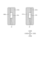
- FIG. 3 is a top view of the internal structure of the second-phase arc-extinguishing chamber of the switch according to embodiment 1.
- FIG. 4 is a schematic cross-sectional view of the internal structure of the second-phase arc-extinguishing chamber of the switch according to embodiment 1.
- FIG. 4 shows a cross-sectional structure of the internal structure of the second-phase arc-extinguishing chamber 21b along line IV-IV in FIG. 3. Note that FIGS.
- the second-phase arc-extinguishing chamber 21b has a fixed contact 23b with a fixed contact 24b, a movable contact 22b with a movable contact 25b, a grid 26b mounted near the fixed contact 24b and the movable contact 25b, and two insulating members 271b, 272b mounted near the grid 26b.
- the grid 26b is made of a magnetic material such as iron.
- the movable contact 25b separates from the fixed contact 24b, and hot gas flows from the movable contact 25b or the fixed contact 24b in the +Y direction along with an arc between the movable contact 25b and the fixed contact 24b.
- the grid 26b forms a flow path that directs the hot gas flowing forward from the movable contact 25b or the fixed contact 24b in the ⁇ X and -Y directions of the movable contact 25b or the fixed contact 24b.
- the grid 26b has the function of reversing the flow direction of the hot gas.
- the dimension of the connecting portion 263b in the Z direction which is the movable direction of the movable contact 22b, is greater than or equal to the dimension in the Y direction.
- the movable contact 25b is covered by the two side portions 261b, 262b and the connecting portion 263b together with the fixed contact 24b.
- the two insulating members 271b, 272b are arranged between the fixed contact 24b and the grid 26b inside the grid 26b so as to expose at least a part of the connecting portion 263b of the grid 26b when viewed from the fixed contact 24b.
- the inside of the grid 26b is the area surrounded on three sides by the connecting portion 263b and the two side portions 261b, 262b.
- hot gas flows from the movable contact 25b and the fixed contact 24b in the +Y direction.
- it hits the connecting portion 263b it changes direction to the ⁇ X direction, and then changes direction to the -Y direction along the side portions 261b, 262b and the insulating members 271b, 272b. Therefore, the hot gas generated between the movable contact 25b and the fixed contact 24b is returned to the surroundings of the movable contact 25b and the fixed contact 24b by the grid 26b.
- the movable contact 22b is driven by the opening and closing mechanism 1B and rotates around the drive shaft 221b shown in FIG. 4.
- the opening and closing mechanism 1B rotates the movable contact 22b around the drive shaft 221b until the movable contact 25b and the fixed contact 24b come into contact.
- the relay unit 1C detects a fault current, it activates the opening and closing mechanism 1B and rotates the movable contact 22b around the drive shaft 221b in a direction in which the movable contact 25b moves away from the fixed contact 24b.
- FIG. 5 is a diagram showing a state in which an arc has been generated between the movable contact and the fixed contact of the switch according to embodiment 1. Immediately after movable contact 25b separates from fixed contact 24b, an arc is generated at position A1 connecting movable contact 25b and fixed contact 24b.
- the switch 1 according to the first embodiment drives the arc generated between the movable contact 25b and the fixed contact 24b in the +Y direction toward the grid 26b by electromagnetic force, and also drives the arc generated between the movable contact 25b and the fixed contact 24b in the +Y direction by the hot gas flow generated between the movable contact 25b and the fixed contact 24b. Furthermore, the switch 1 according to the first embodiment increases the driving force of the arc and improves the cooling effect of the arc by causing the hot gas flow, whose direction of travel has been changed at the connecting portion 263b, to flow in the -Y direction along the side portions 261b and 262b of the grid 26b. As a result, the switch 1 according to the first embodiment can quickly extend and divide the arc to the grid 26b, thereby completing the arc interruption more quickly.
- the switch 1 according to the first embodiment has a dimension in the Z direction, which is the operating direction of the movable contact 22b, that is equal to or greater than the dimension in the Y direction, which is the arrangement direction of the fixed contact 24b and the connecting portion 263b, and has a grid 26b with three or more faces, so that the magnetic volume can be increased and the electromagnetic force acting on the arc can be strengthened. Therefore, the switch 1 according to the first embodiment can quickly stretch and break the arc, thereby quickly completing the arc interruption.
- the insulating members 271b, 272b are installed inside the grid 26b, so that the arc can be moved to the connecting portion 263b, at least a part of which is exposed, without the arc coming into contact with the side portions 261b, 262b of the grid 26b, and the arc can be reliably interrupted.
- Fig. 6 is a perspective view of the internal structure of the second-phase arc extinguishing chamber of the switch according to the second embodiment.
- Fig. 7 is a top view of the internal structure of the second-phase arc extinguishing chamber of the switch according to the second embodiment.
- the switch 1 according to the second embodiment differs from the switch 1 according to the first embodiment in that a gap 91 is formed between each of the insulating members 271b, 272b and the grid 26b.
- a return path X1 is formed between the insulating members 271b, 272b
- a return path X2 is formed between the side portion 261b and the insulating member 271b by the gap 91
- a return path X3 is formed between the side portion 262b and the insulating member 272b by the gap 91.
- the hot gas flows along the inner surface of the grid 26b in the -Y direction through the return path X2 and the return path X3, opposite to the hot gas in the return path X1.
- the gap 91 is formed between each of the insulating members 271b, 272b and the grid 26b, the distance between the insulating members 271b, 272b is narrower than that of the switch 1 according to the first embodiment. Therefore, the flow of hot gas flowing in the +Y direction through the return path X1 formed between the insulating members 271b, 272b is stronger than that of the switch 1 according to the first embodiment.
- the return paths X2, X3 are formed between the insulating members 271b, 272b and the side portions 261b, 262b, the flow of hot gas flowing in the -Y direction along the side portions 261b, 262b and the insulating members 271b, 272b is stronger than that of the switch 1 according to the first embodiment.
- the return paths X1 and the return paths X2, X3 are separated by the insulating members 271b, 272b, the hot gas flowing in the +Y direction and the hot gas flowing in the -Y direction do not interfere with each other and weaken each other.
- FIG. 8 is a top view of the internal structure of the second-phase arc extinguishing chamber of the switch according to the first modified embodiment of the second embodiment.
- FIG. 9 is a cross-sectional view of the internal structure of the second-phase arc extinguishing chamber of the switch according to the first modified embodiment of the second embodiment.
- FIG. 9 shows a cross-section of the internal structure of the second-phase arc extinguishing chamber 21b along the line IX-IX in FIG. 8.
- the insulating members 271b, 272b have lower parts 31b, 32b that face the side parts 261b, 262b and are lower than the side parts 261b, 262b.
- the distance between the lower parts 31b, 32b and the fixed contact 24b in the first direction is shorter than the distance between the end of the side parts 261b, 262b in the first direction and the fixed contact 24b.
- the space above the lower parts 31b, 32b becomes a gap 91, and the return paths X2, X3 are formed.
- FIG. 10 is a top view of the internal structure of the second-phase arc extinguishing chamber of the switch according to the second modified embodiment of the second embodiment.
- FIG. 11 is a cross-sectional view of the internal structure of the second-phase arc extinguishing chamber of the switch according to the second modified embodiment of the second embodiment.
- FIG. 11 shows a cross-section of the second-phase arc extinguishing chamber 21b taken along line XI-XI in FIG. 10.
- grooves 33b and 34b extending in the Y direction are formed in each of the insulating members 271b and 272b.
- the internal spaces of the grooves 33b and 34b form gaps 91, forming return paths X2 and X3.
- the return paths X2 and X3 are formed by at least a portion of either the side surface 261b or the side surface 262b of the grid 26b and the insulating member 271b or the insulating member 272b, and are separated from the return path X1.
- the switch 1 according to the second embodiment includes a return path X1 through which the hot gas flow generated between the movable contact 25b and the fixed contact 24b flows in the +Y direction, and return paths X2 and X3 through which the hot gas flow redirected by the connecting portion 263b flows in the -Y direction, so that the hot gas flow generated between the movable contact 25b and the fixed contact 24b and the hot gas flow returned around the movable contact 25b and the fixed contact 24b can be strengthened and the mutual weakening can be suppressed. Therefore, the switch 1 according to the second embodiment has the same effect as the switch 1 according to the first embodiment, and furthermore, the arc can be quickly stretched to the grid 26b and divided, so that the arc can be interrupted more quickly.
- the hot gas does not necessarily have to branch in the ⁇ X direction at the connecting portion 263b. Therefore, the same effect can be obtained by flowing the hot gas in at least one of the return paths X2 and X3.
- Embodiment 3. 12 is a top view of the internal structure of the second-phase arc-extinguishing chamber of the switch according to embodiment 3.
- the switch 1 according to embodiment 3 differs from the switch 1 according to embodiment 2 in that the insulating members 271b, 272b are arranged such that wall surfaces 291b, 292b of the insulating members 271b, 272b facing the fixed contact 24b are inclined with respect to the side portions 261b, 262b of the grid 26b.
- the insulating member 271b is arranged so that the wall surface 291b and the side surface portion 261b form an angle ⁇ in the XY plane, and similarly, the insulating member 272b is arranged so that the wall surface 292b and the side surface portion 262b form an angle ⁇ ' in the XY plane.
- the angles ⁇ and ⁇ ' do not necessarily have to be the same size.
- the insulating members 271b and 272b can also be configured to have lower portions 31b and 32b.
- the wall surfaces 291b, 292b of the insulating members 271b, 272b that face the fixed contact 24b are inclined with respect to the side surfaces 261b, 262b of the grid 26b, and the closer the insulating members 271b, 272b are to the movable contact 25b and the fixed contact 24b in the Y direction, the faster the flow rate of the hot gas flowing through the return path X1. Therefore, in the switch 1 according to the third embodiment, the force of the hot gas flow driving the arc is strengthened, and the arc is quickly stretched to the grid 26b and broken, completing the arc interruption more quickly.
- Embodiment 4. 13 is a top view of the internal structure of the second-phase arc extinguishing chamber of the switch according to embodiment 4.
- the insulating members 271b and 272b are installed so that the area of the gas outflow surface a of the return paths X2 and X3 is smaller than the area of the gas inflow surface b from the return path X1 to the return paths X2 and X3.
- the areas of the gas outflow surface a and the gas inflow surface b of the return paths X2 and X3 do not necessarily have to be the same, and it is sufficient that the area of the gas outflow surface a ⁇ the area of the gas inflow surface b is satisfied in each of the return paths X2 and X3.
- FIG. 14 is a perspective view of the internal structure of the second-phase arc extinguishing chamber of the switch according to the modified embodiment 4.
- the grid 26b is omitted.
- the inside of the groove 33b extending in the first direction formed in the insulating member 271b becomes a gap 91 to form the return path X2.
- the cross-sectional area of the groove 33b becomes larger as it approaches the connecting portion 263b.
- the insulating member 272b has a groove 34b similar to the groove 33b of the insulating member 271b formed in it, and the inside of the groove 34b becomes a gap 91 to form the return path X3. Therefore, in the switch 1 according to the modified example of embodiment 4, the area of the gas outflow surface a from the return paths X2 and X3 is smaller than the area of the gas inflow surface b from the return path X1 to the return paths X2 and X3.
- the insulating members 271b, 272b may have the lower portions 31b, 32b.
- the height of the lower portions 31b, 32b decreases as they approach the connecting portion 263b along the Y direction, so that the area of the gas outlet surface a of the return paths X2, X3 is smaller than the area of the gas inlet surface b from the return path X1 to the return paths X2, X3.
- the height difference between the side portions 261b, 262b of the grid 26b and the lower portions 31b, 32b of the insulating members 271b, 272b increases as they approach the connecting portion 263b along the Y direction, so that the area of the gas outlet surface a of the return paths X2, X3 is smaller than the area of the gas inlet surface b from the return path X1 to the return paths X2, X3.
- the dimensions of the return channels X2 and X3 in the X direction may be increased as they approach the connecting portion 263b in the Y direction, so that the area of the gas outlet surface a of the return channels X2 and X3 is smaller than the area of the gas inlet surface b from the return channel X1 to the return channels X2 and X3.
- the area of the gas outflow surface a of the return paths X2 and X3 is smaller than the area of the gas inflow surface b, and the return paths X2 and X3 are narrowed in the flow direction, so that the flow rate of the gas blown onto the movable contact 25b and the fixed contact 24b can be increased. Therefore, the switch 1 according to embodiment 4 can further enhance the arc cooling effect compared to the switch 1 according to embodiments 1 to 3, and can more reliably complete the interruption of the arc.
- Embodiment 5. 15 is a top view of the internal structure of the second-phase arc-extinguishing chamber of the switch according to embodiment 5.
- the switch 1 according to embodiment 5 differs from the switch 1 according to embodiment 4 in that it includes gas blowing members 281b, 282b.
- the gas blowing members 281b, 282b are installed adjacent to the ends of the side portions 261b, 262b opposite to the side connected to the connecting portion 263b.
- the surfaces of the gas blowing members 281b, 282b facing the fixed contact 24b are curved so that the further away from the connecting portion 263b the surface is, the closer to the fixed contact 24b it is.
- a return path X4 is formed in the space sandwiched between the insulating member 271b and the gas blowing member 281b, and a return path X5 is formed in the space sandwiched between the insulating member 272b and the gas blowing member 282b.
- the hot gas generated along with the arc between the movable contact 25b and the fixed contact 24b flows from the movable contact 25b or the fixed contact 24b toward the grid 26b.
- the hot gas that collides with the connecting portion 263b branches into ⁇ X directions perpendicular to the Z direction, which is the moving direction of the movable contactor 22b.
- the hot gas flows along the inner surface of the grid 26b in the -Y direction through the return paths X2 and X3, opposite to the hot gas flow in the return path X1.
- the hot gas that has flowed through the return paths X2 and X3 has its direction of travel changed by the gas blowing members 281b and 282b, and the hot gas flows in the return paths X4 and X5 in the direction toward the movable contact 25b and the fixed contact 24b, respectively, and the hot gas is blown against the movable contact 25b and the fixed contact 24b.
- the switch 1 according to the fifth embodiment can efficiently spray hot gas onto the movable contact 25b and the fixed contact 24b, thereby improving the arc cooling effect and more reliably completing the interruption of the arc.
- the switch 1 according to the sixth embodiment differs from the switch 1 according to the second embodiment in that the structure of the grid 26b is different.
- Fig. 16 is a perspective view of the grid of the switch according to the sixth embodiment.
- at least one through hole 264b is provided in at least one of the side portions 261b, 262b of the grid 26b, and the inner space and the outer space of the grid 26b are connected via the through hole 264b. The rest is the same as the switch 1 according to the second embodiment.
- the switch 1 of embodiment 6 can appropriately discharge the hot gas flow flowing through the return paths X2 and X3 out of the return paths X2 and X3, so that the hot gas returns around the movable contact 25b and the fixed contact 24b without remaining in the return paths X2 and X3.
- the switch 1 according to the sixth embodiment can increase the reflux efficiency, which represents the proportion of hot gas generated between the movable contact 25b and the fixed contact 24b that circulates around the movable contact 25b and the fixed contact 24b, and can more reliably complete the interruption of the arc.
- Embodiment 7 The switch 1 according to the seventh embodiment differs from the switch 1 according to the third embodiment in that the structure of the grid 26b is different.
- Fig. 17 is a perspective view of the internal structure of the second-phase arc-extinguishing chamber of the switch 1 according to the seventh embodiment.
- the grid 26b is stacked in a plurality of layers in the moving direction of the movable contact 22b.
- the grids 26b in each layer are not electrically connected to each other.
- the rest of the internal structure is the same as that of the second-phase arc-extinguishing chamber 21b of the switch 1 according to the fifth embodiment.
- the arc generated between the movable contact 25b and the fixed contact 24b is pulled by the stacked grids 26b, and connects the movable contact 25b and the fixed contact 24b with the connecting portion 263b of one of the grids 26b in the middle.
- each grid 26b is electrically connected, and the arc is divided by the grid 26b with the movable contactor 22b and the fixed contactor 23b at both ends.
- the drawn arc can be interrupted by the grids 26b, so the arc voltage can be increased and arc interruption can be completed more reliably.
Landscapes
- Arc-Extinguishing Devices That Are Switches (AREA)
Priority Applications (5)
| Application Number | Priority Date | Filing Date | Title |
|---|---|---|---|
| KR1020257032568A KR20250165607A (ko) | 2023-04-18 | 2023-04-18 | 개폐기 |
| CN202380097129.6A CN120937105A (zh) | 2023-04-18 | 2023-04-18 | 开闭器 |
| JP2025514927A JPWO2024218863A1 (https=) | 2023-04-18 | 2023-04-18 | |
| PCT/JP2023/015477 WO2024218863A1 (ja) | 2023-04-18 | 2023-04-18 | 開閉器 |
| EP23934009.4A EP4700816A1 (en) | 2023-04-18 | 2023-04-18 | Switch |
Applications Claiming Priority (1)
| Application Number | Priority Date | Filing Date | Title |
|---|---|---|---|
| PCT/JP2023/015477 WO2024218863A1 (ja) | 2023-04-18 | 2023-04-18 | 開閉器 |
Publications (1)
| Publication Number | Publication Date |
|---|---|
| WO2024218863A1 true WO2024218863A1 (ja) | 2024-10-24 |
Family
ID=93152161
Family Applications (1)
| Application Number | Title | Priority Date | Filing Date |
|---|---|---|---|
| PCT/JP2023/015477 Ceased WO2024218863A1 (ja) | 2023-04-18 | 2023-04-18 | 開閉器 |
Country Status (5)
| Country | Link |
|---|---|
| EP (1) | EP4700816A1 (https=) |
| JP (1) | JPWO2024218863A1 (https=) |
| KR (1) | KR20250165607A (https=) |
| CN (1) | CN120937105A (https=) |
| WO (1) | WO2024218863A1 (https=) |
Citations (5)
| Publication number | Priority date | Publication date | Assignee | Title |
|---|---|---|---|---|
| JPS5636815A (en) | 1979-08-31 | 1981-04-10 | Matsushita Electric Works Ltd | Arc distinguishing device |
| JPS6064545U (ja) * | 1983-10-11 | 1985-05-08 | 松下電工株式会社 | 消弧装置 |
| JPS6381713A (ja) * | 1986-09-25 | 1988-04-12 | 東芝ライテック株式会社 | 回路遮断器の消弧装置 |
| JPH05135680A (ja) * | 1991-11-11 | 1993-06-01 | Matsushita Electric Works Ltd | 消弧装置 |
| CN111146028A (zh) * | 2020-01-15 | 2020-05-12 | 上海电器科学研究所(集团)有限公司 | 一种直流接触器触头灭弧系统 |
-
2023
- 2023-04-18 EP EP23934009.4A patent/EP4700816A1/en active Pending
- 2023-04-18 KR KR1020257032568A patent/KR20250165607A/ko active Pending
- 2023-04-18 CN CN202380097129.6A patent/CN120937105A/zh active Pending
- 2023-04-18 WO PCT/JP2023/015477 patent/WO2024218863A1/ja not_active Ceased
- 2023-04-18 JP JP2025514927A patent/JPWO2024218863A1/ja active Pending
Patent Citations (5)
| Publication number | Priority date | Publication date | Assignee | Title |
|---|---|---|---|---|
| JPS5636815A (en) | 1979-08-31 | 1981-04-10 | Matsushita Electric Works Ltd | Arc distinguishing device |
| JPS6064545U (ja) * | 1983-10-11 | 1985-05-08 | 松下電工株式会社 | 消弧装置 |
| JPS6381713A (ja) * | 1986-09-25 | 1988-04-12 | 東芝ライテック株式会社 | 回路遮断器の消弧装置 |
| JPH05135680A (ja) * | 1991-11-11 | 1993-06-01 | Matsushita Electric Works Ltd | 消弧装置 |
| CN111146028A (zh) * | 2020-01-15 | 2020-05-12 | 上海电器科学研究所(集团)有限公司 | 一种直流接触器触头灭弧系统 |
Also Published As
| Publication number | Publication date |
|---|---|
| EP4700816A1 (en) | 2026-02-25 |
| KR20250165607A (ko) | 2025-11-26 |
| CN120937105A (zh) | 2025-11-11 |
| JPWO2024218863A1 (https=) | 2024-10-24 |
Similar Documents
| Publication | Publication Date | Title |
|---|---|---|
| JP6516078B1 (ja) | 回路遮断器及び回路遮断方法 | |
| US6163002A (en) | Vacuum circuit interrupter with contact structure including support pins | |
| US11908648B2 (en) | Switch configured to form magnetic fields relative to contact points | |
| CN210956485U (zh) | 分断器、分断器组件和接触器 | |
| CN101625934B (zh) | 电路断路器 | |
| KR20130000677A (ko) | 진공 인터럽터의 전극 조립체 | |
| CN104517789B (zh) | 电路断路器 | |
| WO2024218863A1 (ja) | 開閉器 | |
| JP2010251299A (ja) | 回路遮断器 | |
| US6480080B1 (en) | Molded case circuit breaker | |
| KR20200114835A (ko) | 배선용 차단기의 아크 소호 장치 | |
| US9129761B2 (en) | Switching device suitable for direct current operation | |
| CN112840429B (zh) | 触点开闭器 | |
| JP7774721B2 (ja) | 接点開閉器 | |
| JPH0290424A (ja) | 回路しや断器 | |
| KR100224916B1 (ko) | 회로차단기 | |
| JP2009070601A (ja) | 回路遮断器 | |
| JP7616100B2 (ja) | 開閉器 | |
| KR20250135587A (ko) | 아크 소호용 그리드 어셈블리 및 이를 포함한 아크 소호 장치 | |
| KR102856806B1 (ko) | 차단기용 소호장치 및 이를 포함하는 차단기 | |
| JP2000260271A (ja) | ハイブリッド開閉器 | |
| HK40096535A (en) | Circuit breaker and circuit breaking method | |
| KR102788268B1 (ko) | 배선용 차단기의 아크 소호부 | |
| US20250157760A1 (en) | Arc chute and load break switch comprising same | |
| JP7580990B2 (ja) | 回路遮断器 |
Legal Events
| Date | Code | Title | Description |
|---|---|---|---|
| 121 | Ep: the epo has been informed by wipo that ep was designated in this application |
Ref document number: 23934009 Country of ref document: EP Kind code of ref document: A1 |
|
| WWE | Wipo information: entry into national phase |
Ref document number: 2025514927 Country of ref document: JP |
|
| ENP | Entry into the national phase |
Ref document number: 1020257032568 Country of ref document: KR Free format text: ST27 STATUS EVENT CODE: A-0-1-A10-A15-NAP-PA0105 (AS PROVIDED BY THE NATIONAL OFFICE) |
|
| WWE | Wipo information: entry into national phase |
Ref document number: KR1020257032568 Country of ref document: KR |
|
| WWE | Wipo information: entry into national phase |
Ref document number: 2023934009 Country of ref document: EP |
|
| NENP | Non-entry into the national phase |
Ref country code: DE |
|
| ENP | Entry into the national phase |
Ref document number: 2023934009 Country of ref document: EP Effective date: 20251118 |
|
| ENP | Entry into the national phase |
Ref document number: 2023934009 Country of ref document: EP Effective date: 20251118 |
|
| ENP | Entry into the national phase |
Ref document number: 2023934009 Country of ref document: EP Effective date: 20251118 |
|
| ENP | Entry into the national phase |
Ref document number: 2023934009 Country of ref document: EP Effective date: 20251118 |
|
| ENP | Entry into the national phase |
Ref document number: 2023934009 Country of ref document: EP Effective date: 20251118 |
|
| ENP | Entry into the national phase |
Ref document number: 2023934009 Country of ref document: EP Effective date: 20251118 |
|
| ENP | Entry into the national phase |
Ref document number: 2023934009 Country of ref document: EP Effective date: 20251118 |
|
| ENP | Entry into the national phase |
Ref document number: 2023934009 Country of ref document: EP Effective date: 20251118 |
|
| ENP | Entry into the national phase |
Ref document number: 2023934009 Country of ref document: EP Effective date: 20251118 |
|
| WWP | Wipo information: published in national office |
Ref document number: 2023934009 Country of ref document: EP |