WO2024214630A1 - 真空保存容器 - Google Patents
真空保存容器 Download PDFInfo
- Publication number
- WO2024214630A1 WO2024214630A1 PCT/JP2024/013927 JP2024013927W WO2024214630A1 WO 2024214630 A1 WO2024214630 A1 WO 2024214630A1 JP 2024013927 W JP2024013927 W JP 2024013927W WO 2024214630 A1 WO2024214630 A1 WO 2024214630A1
- Authority
- WO
- WIPO (PCT)
- Prior art keywords
- storage container
- vacuum storage
- chamber
- vacuum
- pump
- Prior art date
- Legal status (The legal status is an assumption and is not a legal conclusion. Google has not performed a legal analysis and makes no representation as to the accuracy of the status listed.)
- Ceased
Links
Images





Classifications
-
- B—PERFORMING OPERATIONS; TRANSPORTING
- B65—CONVEYING; PACKING; STORING; HANDLING THIN OR FILAMENTARY MATERIAL
- B65D—CONTAINERS FOR STORAGE OR TRANSPORT OF ARTICLES OR MATERIALS, e.g. BAGS, BARRELS, BOTTLES, BOXES, CANS, CARTONS, CRATES, DRUMS, JARS, TANKS, HOPPERS, FORWARDING CONTAINERS; ACCESSORIES, CLOSURES, OR FITTINGS THEREFOR; PACKAGING ELEMENTS; PACKAGES
- B65D81/00—Containers, packaging elements, or packages, for contents presenting particular transport or storage problems, or adapted to be used for non-packaging purposes after removal of contents
- B65D81/18—Containers, packaging elements, or packages, for contents presenting particular transport or storage problems, or adapted to be used for non-packaging purposes after removal of contents providing specific environment for contents, e.g. temperature above or below ambient
- B65D81/20—Containers, packaging elements, or packages, for contents presenting particular transport or storage problems, or adapted to be used for non-packaging purposes after removal of contents providing specific environment for contents, e.g. temperature above or below ambient under vacuum or superatmospheric pressure, or in a special atmosphere, e.g. of inert gas
-
- B—PERFORMING OPERATIONS; TRANSPORTING
- B65—CONVEYING; PACKING; STORING; HANDLING THIN OR FILAMENTARY MATERIAL
- B65D—CONTAINERS FOR STORAGE OR TRANSPORT OF ARTICLES OR MATERIALS, e.g. BAGS, BARRELS, BOTTLES, BOXES, CANS, CARTONS, CRATES, DRUMS, JARS, TANKS, HOPPERS, FORWARDING CONTAINERS; ACCESSORIES, CLOSURES, OR FITTINGS THEREFOR; PACKAGING ELEMENTS; PACKAGES
- B65D81/00—Containers, packaging elements, or packages, for contents presenting particular transport or storage problems, or adapted to be used for non-packaging purposes after removal of contents
- B65D81/24—Adaptations for preventing deterioration or decay of contents; Applications to the container or packaging material of food preservatives, fungicides, pesticides or animal repellants
- B65D81/26—Adaptations for preventing deterioration or decay of contents; Applications to the container or packaging material of food preservatives, fungicides, pesticides or animal repellants with provision for draining away, or absorbing, or removing by ventilation, fluids, e.g. exuded by contents; Applications of corrosion inhibitors or desiccators
Definitions
- the present invention relates to a vacuum storage container.
- the present invention was made in consideration of the above, and aims to provide a vacuum storage container that can prevent condensation from occurring when it is placed outside a refrigerator.
- the vacuum storage container of the present invention comprises a storage chamber for storing an object to be stored, a machine chamber separated from the storage chamber and for storing equipment including a pump that sucks in gas from inside the storage chamber and exhausts it to the outside, and a condensation suppression means for suppressing condensation inside the machine chamber.
- One aspect of the vacuum storage container according to the present invention makes it possible to prevent condensation from occurring when the container is placed outside the refrigerator.
- FIG. 1 is a perspective view of a vacuum storage container according to a first embodiment.
- FIG. 2 is a perspective view showing the vacuum storage container shown in FIG. 1 with a cover removed from the case.
- FIG. 3 is a schematic cross-sectional view of the vacuum storage container shown in FIG.
- FIG. 4 is a schematic block diagram showing electrical connections of each part of the vacuum storage container shown in FIG.
- FIG. 5 is a schematic diagram of a vacuum storage container according to the second embodiment.
- FIG. 6 is a schematic diagram of a vacuum storage container according to the third embodiment.
- FIG. 7 is a schematic diagram of a vacuum storage container according to the fourth embodiment.
- FIG. 8 is a schematic diagram of a vacuum storage container according to the fifth embodiment.
- Fig. 1 is a perspective view of a vacuum storage container 1 according to a first embodiment.
- Fig. 2 is a perspective view showing a state in which a cover 2b is removed from a case 2a in the vacuum storage container 1 shown in Fig. 1.
- Fig. 3 is a schematic cross-sectional view of the vacuum storage container 1 shown in Fig. 1.
- Fig. 4 is a schematic block diagram showing electrical connections of each part of the vacuum storage container 1 shown in Fig. 1.
- the X-axis will be referred to as the front-to-rear direction, the Y-axis as the left-to-right direction, and the Z-axis as the up-to-down direction Z for the sake of convenience.
- the front-to-rear direction X, the left-to-right direction Y, and the up-to-down direction Z are mutually perpendicular.
- the vacuum storage container 1 is formed small enough to fit inside a refrigerator. The vacuum storage container 1 is then placed inside the refrigerator, and the storage object 4o stored inside the vacuum storage container 1 can be refrigerated.
- the vacuum storage container 1 includes a housing 2 and a control unit 3.
- the housing 2 is formed, for example, in the shape of a rectangular box, and includes a case 2a and a cover 2b.
- the housing 2 also includes a storage chamber 2ar and a machine chamber 2br, which will be described later.
- the case 2a for example, has a bottom wall 21a and a side wall 22a, and has an opening 2o at its upper end in the vertical direction Z.
- a gasket 23a is provided along the opening 2o at the upper end of the side wall 22a.
- the gasket 23a is a sealing member that seals the case 2a and the cover 2b.
- the case 2a stores items to be stored 4o in the storage chamber 2ar formed by the bottom wall 21a and the side wall 22a.
- the items that are the storage objects 4o are, for example, beverages, food, seasonings, etc. Of course, items other than these items may also be the storage objects 4o.
- the cover 2b has, for example, a top wall 21b, a partition wall 22b that faces the top wall 21b in the vertical direction Z, and a side wall 23b. As shown in FIG. 3, when the cover 2b is closed on the case 2a, the partition wall 22b faces the bottom wall 21a in the vertical direction Z.
- the cover 2b stores the equipment 7 in a machine room 2br that is formed by the top wall 21b, the partition wall 22b, and the side wall 23b. In other words, the machine room 2br is provided separately from the storage room 2ar.
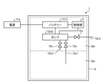
- the machine room 2br houses equipment 7 such as a battery (cell) 71 and a pump 72.
- the battery 71 is, for example, a battery pack made up of a combination of secondary batteries such as lithium ion batteries, and can be charged (store electricity) when electrically connected to an external power source 71a. When the battery 71 is in a stored state, it can supply power to equipment 7 such as the pump 72.
- the pump 72 is capable of pumping out gas using power supplied from the battery 71.
- the pump 72 according to this embodiment includes a first suction path 72r1, a second suction path 72r2, and a discharge path 72r3, and an on-off valve 72v provided in each of the paths 72r1, 72r2, and 72r3.
- the on-off valve 72v is electrically connected to the control unit 3, and each of 72r1, 72r2, and 72r3 can be opened and closed individually based on a command from the control unit 3.
- the first suction path 72r1 is provided between the pump 72 and the storage chamber 2ar.
- the control unit 3 can cause the pump 72 to suck in the gas inside the storage chamber 2ar via the first suction path 72r1.
- the second suction path 72r2 is provided between the pump 72 and the machine chamber 2br.
- the control unit 3 can cause the pump 72 to suck in the gas inside the machine chamber 2br via the second suction path 72r2.
- the exhaust path 72r3 is provided between the pump 72 and the outside of the housing 2.
- the control unit 3 can use the pump 72 to exhaust the gas sucked from the storage chamber 2ar or the gas sucked from the machine chamber 2br to the outside via the exhaust path 72r3.
- the control unit 3 has the function of comprehensively controlling the devices 7 such as the pump 72 and the on-off valve 72v.
- the control unit 3 is, for example, configured with electronic devices mounted on a circuit board (not shown) and is disposed in the machine room 2br.
- the control unit 3 drives the pump 72 to reduce the pressure in the storage chamber 2ar to a predetermined pressure lower than atmospheric pressure (hereinafter referred to as "vacuum").
- vacuum refers to a state in which the predetermined pressure is lower than atmospheric pressure.
- the control unit 3 can also put the machine room 2br into a vacuum state by driving the pump 72. By putting the machine room 2br into a vacuum state, condensation inside the machine room 2br can be suppressed.
- the pump 72 functions as a condensation suppression means 6.
- the housing 2 is also provided with an open valve (not shown).
- the open valve is provided midway along the path between the storage chamber 2ar and the outside of the housing 2.
- the storage chamber 2ar When the release valve is opened, the storage chamber 2ar is in communication with the outside. Therefore, when the storage chamber 2ar is in a vacuum state, if the release valve is opened, external gas flows into the storage chamber 2ar, the storage chamber 2ar becomes at atmospheric pressure, and it becomes possible to open the cover 2b relative to the case 2a.
- the housing 2 is also provided with a switch (not shown) for starting and stopping the pump 72.
- the gas (air) in the storage chamber 2ar can be discharged to the outside by the pump 72, thereby lowering the pressure in the storage chamber 2ar and decreasing the oxygen concentration. Therefore, with the vacuum storage container 1 according to this embodiment, it is possible to prevent oxidation of the storage object 4o in the storage chamber 2ar due to contact with oxygen. As a result, the freshness of the storage object 4o, such as beverages and food, stored in the storage chamber 2ar can be maintained for a long period of time.
- the vacuum storage container 1 includes a storage chamber 2ar for storing the storage object 4o, a machine chamber 2br that is partitioned from the storage chamber 2ar and stores equipment 7 including a pump 72 that sucks gas from inside the storage chamber 2ar and exhausts it to the outside, and a condensation suppression means 6 that suppresses condensation inside the machine chamber 2br. Therefore, by suppressing condensation inside the machine chamber 2br, the life of the equipment 7 such as the pump 72 stored in the machine chamber 2br can be extended.
- the vacuum storage container 1 according to this embodiment is formed small enough to fit inside a refrigerator. Therefore, by placing the vacuum storage container 1 inside a refrigerator, the storage object 4o can be refrigerated. Therefore, the vacuum storage container 1 according to this embodiment can store the storage object 4o, such as beverages and food, in the vacuum storage container 1 in a cooled state, so that the freshness of the storage object 4o can be maintained for a long period of time.
- the vacuum storage container 1 further comprises a housing 2 in which a storage chamber 2ar and a machine chamber 2br are formed, and the housing 2 comprises a case 2a having an opening 2o, a cover 2b for opening and closing the opening 2o, and a packing (sealing member) 23a that is provided along the opening 2o and seals the case 2a and the cover 2b.
- the above-mentioned vacuum storage container 1 has been described as an example in which the pump 72 is used as the condensation suppression means 6.
- the condensation suppression means 6 of the vacuum storage container 1 according to this embodiment is not limited to this, and other equipment 7, etc., described below, can be used. In that case, there is no need to provide the second suction path 72r2 between the pump 72 and the machine chamber 2br.
- a pump that sucks in the gas inside the machine chamber 2br and discharges it to the outside and a pump that sucks in the gas inside the storage chamber 2ar and discharges it to the outside may be provided separately.
- FIG. 5 is a schematic diagram of the vacuum storage container 1A according to the second embodiment. Note that in the configuration of the vacuum storage container 1A according to the second embodiment, the same components as those of the vacuum storage container 1 according to the first embodiment are denoted by the same reference numerals and will not be described.
- a fan 62 is provided in the machine room 2br of the vacuum storage container 1A. Although not shown, the fan 62 is electrically connected to a battery 71 and receives power from the battery 71. The fan 62 is also a device 7 provided in the machine room 2br. Furthermore, although not shown, the fan 62 is electrically connected to the control unit 3 and is driven in response to commands from the control unit 3.
- the fan 62 When the fan 62 is driven by the control unit 3, the air inside the machine room 2br can be circulated.
- the fan 62 functions as a convection device 5 that circulates the air inside the machine room 2br.
- the fan 62 functions as a condensation suppression means 6 that suppresses condensation inside the machine room 2br.
- the fan 62 is a convection device 5 that circulates the air inside the machine chamber 2br, and also functions as a condensation suppression means 6.
- the pump 72 described above may be used as the convection device 5. More specifically, the pump 72 may have a function of sucking gas from inside the machine chamber 2br and discharging it into the machine chamber 2br. In this case, the pump 72 sucks gas from the second suction path 72r2 and discharges it into the machine chamber 2br from a discharge path (not shown). The discharge path (not shown) is provided from the pump 72 to the inside of the machine chamber 2br. A partition plate may be provided between the second suction path 72r2 and the discharge path (not shown) to form a gas movement path. The pump 72 may also have a function of sucking gas from the outside of the machine chamber 2br and discharging it into the inside of the machine chamber 2br.
- the pump 72 sucks gas from a suction path (not shown).
- the suction path (not shown) is provided between the pump 72 and the outside of the machine chamber 2br.
- the gas discharged into the machine chamber 2br is discharged to the outside of the machine chamber from an open valve (not shown).
- the open valve is provided in the middle of a path provided between the machine chamber 2br and the outside of the housing 2.
- the pump 72 may also have a function of sucking gas from an open valve (not shown) when sucking gas from the outside of the machine chamber 2br. In this case, the pump 72 sucks gas from the second suction path 72r2 and exhausts it to the outside of the machine chamber 2br from the exhaust path 72r3.
- the pump 72 circulates gas within the machine chamber 2br or takes in gas from outside the machine chamber 2br, thereby convecting the gas inside the machine chamber 2br.
- the pump 72 can be used as a convection device 5 and a condensation suppression means 6.
- the condensation suppression means 6 is a pump 72 that circulates the gas inside the machine chamber 2br. Therefore, in the vacuum storage container 1A according to this embodiment, the pump 72 has the function of circulating the gas inside the machine chamber 2br. Therefore, the vacuum storage container 1A according to this embodiment can be made inexpensive by reducing the number of pumps. Note that in the vacuum storage container 1A according to this embodiment, the pump that circulates the gas inside the machine chamber 2br and the pump that sucks in the gas inside the storage chamber 2ar and discharges it to the outside may be provided separately.
- FIG. 6 is a schematic diagram of the vacuum storage container 1B according to the third embodiment.
- the same components as those of the vacuum storage container 1 according to the first embodiment are denoted by the same reference numerals and will not be described.
- a heater 63 is provided in the machine room 2br of the vacuum storage container 1B.
- the heater 63 is electrically connected to a battery 71 and receives power from the battery 71.
- the heater 63 is also a device 7 provided in the machine room 2br.
- the heater 63 is further electrically connected to the control unit 3 and starts up in response to a command from the control unit 3.
- the heater 63 When the heater 63 is activated by the control unit 3, the temperature inside the machine room 2br rises. In other words, the heater 63 functions as a condensation suppression means 6 that suppresses condensation inside the machine room 2br.
- the heater 63 is the condensation suppression means 6 that suppresses condensation inside the machine chamber 2br.
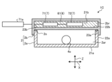
- FIG. 7 is a schematic diagram of the vacuum storage container 1C according to the fourth embodiment. Note that in the configuration of the vacuum storage container 1C according to the fourth embodiment, the same components as those of the vacuum storage container 1 according to the first embodiment are denoted by the same reference numerals and will not be described.
- the machine chamber 2br of the vacuum storage container 1C is filled with a heat insulating material 61.
- the heat insulating material 61 is, for example, a resin such as urethane foam.
- Such a heat insulating material 61 functions as a condensation suppression means 6 that suppresses condensation inside the machine chamber 2br.
- the condensation suppression means 6 is a heat insulating member 61 that suppresses the transfer of heat from the outside to the machine chamber 2br.
- FIG. 8 is a schematic diagram of the vacuum storage container 1D according to the fifth embodiment. Note that in the configuration of the vacuum storage container 1D according to the fifth embodiment, the same components as those of the vacuum storage container 1 according to the first embodiment are denoted by the same reference numerals and will not be described.
- a first coil 91 is provided in the machine chamber 2br of the vacuum storage container 1D.
- the first coil 91 is electrically connected to the battery 71.
- Such a first coil 91 is attached, for example, to the inner surface of the top wall 21b.
- the first coil 91 is disposed inside the machine chamber 2br.
- the first coil 91 is disposed inside the housing 2.
- a second coil 92 connected to an AC power source 93 is disposed on the outer surface of the top wall 21b of the housing 2.
- the first coil 91 and the second coil 92 form a charging device 9 for the battery 71. More specifically, the first coil 91 and the second coil 92 are disposed so as to face each other in the vertical direction Z via the top wall 21b.
- the second coil 92 is electrically connected to the AC power source 93, a magnetic flux is generated in the second coil 92, the magnitude of which changes over time.
- the vacuum storage container 1D further includes a housing 2 having a storage chamber ar and a machine chamber br, a battery (cell) 71 arranged in the machine chamber br, and a charging device 9 for charging the battery 71.
- the charging device 9 includes a first coil 91 arranged inside the housing 2 and a second coil 92 arranged outside the housing 2. When the second coil 92 is connected to an AC power source 93, an induced electromotive force is generated in the first coil 91 to charge the battery 71. Therefore, the vacuum storage container 1D does not require electrical wiring extending from the inside of the housing 2 to the outside of the housing 2.
- the vacuum storage container 1D can suppress the deterioration of the function of the heat insulating member 61 that suppresses the transfer of heat from the outside to the machine chamber 2br, which is caused by the electrical wiring, by the charging device 9. Furthermore, the vacuum storage container 1D can suppress the deterioration of the function of the condensation prevention means that suppresses condensation occurring inside the machine chamber 2br by putting the machine chamber 2br into a vacuum state, which is caused by the electrical wiring, by the charging device 9.
- 1, 1A, 1B, 1C, 1D vacuum storage container
- 2 housing
- 2a case, 2ar: storage chamber
- 2o opening
- 2b cover
- 2br machine chamber
- 23a packing (sealing member)
- 5 convection device
- 6 condensation suppression means
- 61 heat insulating member
- 63 heater
- 72 pump
- 9 charging device
- 91 first coil
- 92 second coil
- 93 AC power source
Landscapes
- Engineering & Computer Science (AREA)
- Mechanical Engineering (AREA)
- Food Science & Technology (AREA)
- Storage Of Fruits Or Vegetables (AREA)
- Compressors, Vaccum Pumps And Other Relevant Systems (AREA)
- Vacuum Packaging (AREA)
- Packages (AREA)
Abstract
真空保存容器(1)は、保存対象を収納する収納室(2ar)と、前記収納室(2ar)とは区画して設けられ、前記収納室(2ar)の内部の気体を吸引して外部に排出するポンプ(72)を含む機器を収納する機械室(2br)と、前記機械室(2br)の内部の結露を抑制する結露抑制手段(6)と、を備える。
Description
本発明は、真空保存容器に関する。
内部に収納する食品の保存状態を維持する密封式の真空保存容器が知られている(例えば、特許文献1参照)。
しかしながら、特許文献1に記載された技術では、真空保存容器を、例えば冷蔵庫で保存した後、冷蔵庫の外部に出した場合には結露が発生する。
本発明は、上記に鑑みてなされたものであって、冷蔵庫の外部に出した状態において、結露の発生を抑制することができる真空保存容器を提供することにある。
上述した課題を解決し、目的を達成するために、本発明に係る真空保存容器は、保存対象を収納する収納室と、前記収納室とは区画して設けられ、前記収納室の内部の気体を吸引して外部に排出するポンプを含む機器を収納する機械室と、前記機械室の内部の結露を抑制する結露抑制手段と、を備える。
本発明に係る真空保存容器の一態様によれば、冷蔵庫の外部に出した状態において、結露の発生を抑制することができる。
以下、実施形態に係る真空保存容器について図面を参照して説明する。なお、この実施形態によりこの発明が限定されるものではない。また、図面における各要素の寸法の関係、各要素の比率などは、現実と異なる場合がある。図面の相互間においても、互いの寸法の関係や比率が異なる部分が含まれている場合がある。また、1つの実施形態や変形例に記載された内容は、原則として他の実施形態や変形例にも同様に適用される。
[第1実施形態]
図1は、第1実施形態に係る真空保存容器1の斜視図である。図2は、図1に示す真空保存容器1において、ケース2aに対してカバー2bを取り外した状態を示す斜視図である。図3は、図1に示す真空保存容器1の模式的な断面図である。図4は、図1に示す真空保存容器1の各部の電気的な接続を示す模式的なブロック図である。
図1は、第1実施形態に係る真空保存容器1の斜視図である。図2は、図1に示す真空保存容器1において、ケース2aに対してカバー2bを取り外した状態を示す斜視図である。図3は、図1に示す真空保存容器1の模式的な断面図である。図4は、図1に示す真空保存容器1の各部の電気的な接続を示す模式的なブロック図である。
第1実施形態に係る図1~図4に示す真空保存容器1の説明において、方向の理解を容易にするため、便宜的にX軸を前後方向と呼び、Y軸を左右方向と呼び、Z軸を上下方向Zと呼ぶ。そして、前後方向Xと、左右方向Yと、上下方向Zとは、相互に直交する。
本実施形態に係る真空保存容器1は、冷蔵庫の内部に収容することができるように小型に形成される。そして、冷蔵庫の内部に真空保存容器1を入れ、その真空保存容器1の内部に収納する保存対象4oを冷蔵することができる。
真空保存容器1は、ハウジング2と、制御部3と、を備える。ハウジング2は、例えば、直方体の箱状に形成され、ケース2aと、カバー2bと、を備える。また、ハウジング2は、後述する収納室2arおよび機械室2brを有する。
ケース2aは、例えば、底壁21aと側壁22aとを有するとともに、上下方向Zにおける上端に開口2oを有する。また、側壁22aの上端には、開口2oに沿ってパッキン23aが設けられる。パッキン23aは、ケース2aとカバー2bとを密閉する密閉部材である。そして、ケース2aは、底壁21aと側壁22aとによって形成される収納室2arに、保存対象4oである物品を収納する。
保存対象4oである物品は、例えば、飲料、食品、調味料等である。もちろん、これらの物品とは異なる物品を保存対象4oとしてもよい。
カバー2bは、例えば、天壁21bと、上下方向Zにおいて天壁21bと対向する隔壁22bと、側壁23bと、を有する。隔壁22bは、図3に示すように、ケース2aに対してカバー2bを閉じた状態では、上下方向Zにおいて底壁21aに対向する。そして、カバー2bは、天壁21bと隔壁22bと側壁23bとによって形成される機械室2brに、機器7を収納する。つまり、機械室2brは、収納室2arとは区画して設けられる。
機械室2brには、バッテリー(電池)71およびポンプ72等の機器7が収納される。バッテリー71は、例えば、複数のリチウムイオン電池のような二次電池を組み合わせた組電池であり、外部に設けられた電源71aに対して電気的に接続された場合には充電(蓄電)することができる。そして、バッテリー71は、蓄電された状態では、ポンプ72等の機器7に電力を供給することができる。
ポンプ72は、バッテリー71から供給された電力によって、気体を送り出すことが可能である。本実施形態に係るポンプ72には、第1吸引経路72r1と、第2吸引経路72r2と、排出経路72r3とを、それぞれの経路72r1、72r2、72r3の途中に設けられた開閉弁72vと、備える。開閉弁72vは、制御部3に対して電気的に接続され、制御部3からの指令に基づいてそれぞれの72r1、72r2、72r3の開閉を個別に行うことが可能である。
第1吸引経路72r1は、ポンプ72と、収納室2arとの間に設けられる。そして、制御部3は、開閉弁72vを開いた状態では、第1吸引経路72r1を介して収納室2arの内部の気体をポンプ72で吸引することができる。
第2吸引経路72r2は、ポンプ72と、機械室2brとの間に設けられる。そして、制御部3は、開閉弁72vを開いた状態では、第2吸引経路72r2を介して機械室2brの内部の気体をポンプ72で吸引することができる。
排出経路72r3は、ポンプ72と、ハウジング2の外部との間に設けられる。そして、制御部3は、開閉弁72vを開いた状態では、収納室2arから吸引した気体、または、機械室2brから吸引した気体を、排出経路72r3を介してポンプ72で外部に排出することができる。
制御部3は、ポンプ72および開閉弁72v等の機器7を統括的に制御する機能を有する。制御部3は、例えば、不図示の回路基板に設けられた電子機器によって構成され、機械室2brに配置される。例えば、制御部3は、ケース2aの開口2oをカバー2bで閉じた状態において、ポンプ72を駆動させることで、収納室2arの圧力を大気圧よりも所定の圧力を減圧した低圧力の状態(以下、「真空」と称呼する)にする。つまり、本実施形態において、「真空」とは、大気圧に比べて所定の圧力が低い状態を言う。そして、収納室2arが真空になると、ケース2aに対してカバー2bが押圧され、パッキン23aが弾性変形することによって、収納室2arの真空状態が維持される。
また、制御部3は、ポンプ72を駆動させることで、機械室2brを真空状態にすることができる。機械室2brを真空状態にすることによって、機械室2brの内部の結露を抑制することができる。言い換えれば、ポンプ72は、結露抑制手段6としての機能を有する。
また、ハウジング2には、不図示の開放弁が設けられる。開放弁は、収納室2arとハウジング2の外部との間に設けられた経路の途中に設けられる。
開放弁を開いた場合には、収納室2arと外部とが連通した状態になる。そのため、収納室2arが真空状態の場合に、開放弁を開いた場合には、外部の気体が収納室2arに流入して、収納室2arが大気圧となり、ケース2aに対してカバー2bを開くことが可能になる。
一方、開放弁を閉じた場合には、収納室2arと外部との連通が遮断された状態になる。そのため、この状態でポンプ72を駆動した場合には、収納室2arの圧力を大気圧よりも低くすることができる。
また、ハウジング2には、ポンプ72の駆動および駆動を停止するためのスイッチ(不図示)が設けられる。
以上に説明したように、本実施形態に係る真空保存容器1によれば、収納室2arの気体(空気)をポンプ72によって外部に排出することで、収納室2arの圧力を低下することができるとともに、酸素濃度を減少させることができる。そのため、本実施形態に係る真空保存容器1によれば、収納室2arにおいて、保存対象4oが酸素に接触することによる酸化を防止することができる。その結果、収納室2arに収納する飲料および食品等の保存対象4oの鮮度を、長い期間にわたって維持することができる。
本実施形態に係る真空保存容器1は、保存対象4oを収納する収納室2arと、収納室2arとは区画して設けられ、収納室2arの内部の気体を吸引して外部に排出するポンプ72を含む機器7を収納する機械室2brと、機械室2brの内部の結露を抑制する結露抑制手段6を備える。そのため、機械室2brの内部の結露を抑制することによって、機械室2brに収納されたポンプ72等の機器7の寿命を長くすることができる。
本実施形態に係る真空保存容器1は、冷蔵庫の内部に収容することができるように小型に形成される。そのため、冷蔵庫の内部に真空保存容器1を入れることで、保存対象4oを冷蔵することができる。したがって、本実施形態に係る真空保存容器1は、飲料および食品等の保存対象4oを冷却した状態で、真空保存容器1に保存することができるため、保存対象4oの鮮度を、長い期間にわたって維持することができる。
本実施形態に係る真空保存容器1は、収納室2arと機械室2brとが内部に形成されたハウジング2をさらに備え、ハウジング2は、開口2oを有するケース2aと、開口2oを開閉するカバー2bと、開口2oに沿って設けられ、ケース2aとカバー2bとを密閉するパッキン(密封部材)23aと、を備える。
なお、上述した真空保存容器1は、ポンプ72を結露抑制手段6として用いる例を説明した。しかし、本実施形態に係る真空保存容器1の結露抑制手段6は、それに限られず、後述する他の機器7等を用いることができる。その場合、ポンプ72と機械室2brとの間に設けられる第2吸引経路72r2を設ける必要はない。
また、本実施形態に係る真空保存容器1において、機械室2brの内部の気体を吸引して外部に排出するポンプと、収納室2arの内部の気体を吸引して外部に排出するポンプとを、別々に設けても良い。
[第2実施形態]
次に、第2実施形態に係る真空保存容器1Aに関して図5を用いて説明する。図5は、第2実施形態に係る真空保存容器1Aの模式図である。なお、第2実施形態に係る真空保存容器1Aの構成において、第1実施形態に係る真空保存容器1と同一の構成については、同一の符号を付して説明を省略する。
次に、第2実施形態に係る真空保存容器1Aに関して図5を用いて説明する。図5は、第2実施形態に係る真空保存容器1Aの模式図である。なお、第2実施形態に係る真空保存容器1Aの構成において、第1実施形態に係る真空保存容器1と同一の構成については、同一の符号を付して説明を省略する。
真空保存容器1Aの機械室2brには、ファン62が設けられる。ファン62は、図示省略するが、バッテリー71に対して電気的に接続され、バッテリー71から電力が供給される。また、ファン62は、機械室2brに設けられた機器7である。さらに、ファン62は、図示省略するが、制御部3に対して電気的に接続され、制御部3からの指令に応じて駆動する。
そして、制御部3によって、ファン62を駆動した場合には、機械室2brの内部の空気を循環することができる。つまり、ファン62は、機械室2brの内部の空気を対流させる対流装置5としての機能を有する。その上、ファン62は、機械室2brの内部の結露を抑制する結露抑制手段6としての機能を有する。
本実施形態に係る真空保存容器1Aにおいて、ファン62は、機械室2brの内部の空気を対流させる対流装置5であり、かつ、結露抑制手段6としての機能を有する。
なお、対流装置5として、上述したポンプ72を利用してもよい。より具体的に説明すると、ポンプ72は、機械室2brの内部の気体を吸引して、機械室2brの内部に排出する機能を有しても良い。この場合、ポンプ72は、第2吸引経路72r2から気体を吸引し、不図示の排出経路から機械室2brの内部に排出する。不図示の排出経路は、ポンプ72から機械室2brの内部に設けられる。第2吸引経路72r2と不図示の排出経路との間には仕切り板を設けることで、気体の移動経路が形成されても良い。また、ポンプ72は、機械室2brの外部から気体を吸引し、機械室2brの内部に排出する機能を有しても良い。この場合、ポンプ72は、不図示の吸引経路から気体を吸引する。不図示の吸引経路は、ポンプ72と、機械室2brの外部との間に設けられる。機械室2brの内部に排出された気体は、不図示の開放弁から機械室外に排出される。開放弁は、機械室2brとハウジング2の外部との間に設けられた経路の途中に設けられる。また、ポンプ72は、機械室2brの外部から気体を吸引するにあたり、不図示の開放弁から気体を吸引する機能を有しても良い。この場合、ポンプ72、第2吸引経路72r2から気体を吸引し、排出経路72r3から機械室2brの外部に排出する。このように、ポンプ72が機械室2br内で気体を循環、又は機械室2br外から気体を取り込むことで、機械室2brの内部の気体を対流させることができる。つまり、ポンプ72を対流装置5であって、結露抑制手段6として用いることができる。
本実施形態に係る真空保存容器1Aにおいて、結露抑制手段6は、機械室2brの内部の気体を対流させるポンプ72である。そのため、本実施形態に係る真空保存容器1Aにおいて、ポンプ72は、機械室2brの内部の気体を対流させる機能を有する。従って、本実施形態に係る真空保存容器1Aは、ポンプの数を減少させることで、真空保存容器1Aを安価にすることができる。なお、本実施形態に係る真空保存容器1Aにおいて、機械室2brの内部の気体を対流させるポンプと、収納室2arの内部の気体を吸引して外部に排出するポンプとを、別々に設けても良い。
[第3実施形態]
次に、第3実施形態に係る真空保存容器1Bに関して図6を用いて説明する。図6は、第3実施形態に係る真空保存容器1Bの模式図である。なお、第3実施形態に係る真空保存容器1Bの構成において、第1実施形態に係る真空保存容器1と同一の構成については、同一の符号を付して説明を省略する。
次に、第3実施形態に係る真空保存容器1Bに関して図6を用いて説明する。図6は、第3実施形態に係る真空保存容器1Bの模式図である。なお、第3実施形態に係る真空保存容器1Bの構成において、第1実施形態に係る真空保存容器1と同一の構成については、同一の符号を付して説明を省略する。
真空保存容器1Bの機械室2brには、ヒータ63が設けられる。ヒータ63は、バッテリー71に対して電気的に接続され、バッテリー71から電力が供給される。また、ヒータ63は、機械室2brに設けられた機器7である。さらに、ヒータ63は、制御部3に対して電気的に接続され、制御部3からの指令に応じて起動する。
そして、制御部3によって、ヒータ63を起動した場合には、機械室2brの内部の温度が上昇する。つまり、ヒータ63は、機械室2brの内部の結露を抑制する結露抑制手段6としての機能を有する。
本実施形態に係る真空保存容器1Bにおいて、ヒータ63は、機械室2brの内部の結露を抑制する結露抑制手段6である。
[第4実施形態]
次に、第4実施形態に係る真空保存容器1Cに関して図7を用いて説明する。図7は、第4実施形態に係る真空保存容器1Cの模式図である。なお、第4実施形態に係る真空保存容器1Cの構成において、第1実施形態に係る真空保存容器1と同一の構成については、同一の符号を付して説明を省略する。
次に、第4実施形態に係る真空保存容器1Cに関して図7を用いて説明する。図7は、第4実施形態に係る真空保存容器1Cの模式図である。なお、第4実施形態に係る真空保存容器1Cの構成において、第1実施形態に係る真空保存容器1と同一の構成については、同一の符号を付して説明を省略する。
真空保存容器1Cの機械室2brには、断熱部材61が充填される。断熱部材61は、例えば、発泡ウレタン等の樹脂である。このような断熱部材61は、機械室2brの内部の結露を抑制する結露抑制手段6として機能する。
本実施形態に係る真空保存容器1Cにおいて、結露抑制手段6は、外部から機械室2brに対する熱の伝達を抑制する断熱部材61である。
[第5実施形態]
次に、第5実施形態に係る真空保存容器1Dに関して図8を用いて説明する。図8は、第5実施形態に係る真空保存容器1Dの模式図である。なお、第5実施形態に係る真空保存容器1Dの構成において、第1実施形態に係る真空保存容器1と同一の構成については、同一の符号を付して説明を省略する。
次に、第5実施形態に係る真空保存容器1Dに関して図8を用いて説明する。図8は、第5実施形態に係る真空保存容器1Dの模式図である。なお、第5実施形態に係る真空保存容器1Dの構成において、第1実施形態に係る真空保存容器1と同一の構成については、同一の符号を付して説明を省略する。
真空保存容器1Dの機械室2brには、第1コイル91が設けられる。第1コイル91は、バッテリー71に対して電気的に接続される。このような第1コイル91は、例えば、天壁21bの内面に取り付けられる。つまり、第1コイル91は、機械室2brの内部に配置される。換言すれば、第1コイル91は、ハウジング2の内部に配置される。
また、ハウジング2の天壁21bの外面には、交流電源93に対して接続された第2コイル92が配置される。そして、第1コイル91および第2コイル92によって、バッテリー71に対する充電装置9が形成される。より具体的に説明すると、第1コイル91と第2コイル92とは、天壁21bを介して上下方向Zに対向するように配置される。そして、第2コイル92が交流電源93に対して電気的に接続されると、第2コイル92には、時間の経過によって磁力の大きさが変化する磁束が発生する。
第2コイル92に、時間の経過によって磁力の大きさが変化する磁束が発生すると、その第2コイル92の磁束によって、第1コイル91には、誘導起電力が発生し、この誘導起電力によってバッテリー71が蓄電される。
本実施形態に係る真空保存容器1Dは、収納室arおよび機械室brを有するハウジング2と、機械室brに配置されたバッテリー(電池)71と、バッテリー71の充電を行う充電装置9と、をさらに備える。そして、充電装置9は、ハウジング2の内部に配置された第1コイル91と、ハウジング2の外部に配置された第2コイルと92、とを備え、第2コイル92が交流電源93に対して接続された場合には、第1コイル91に誘導起電力が発生してバッテリー71が充電される。そのため、真空保存容器1Dは、ハウジング2の内部からハウジング2の外部に延びる電気配線が不要となる。そのため、この真空保存容器1Dは、充電装置9によって、電気配線に起因する、外部から機械室2brに対する熱の伝達を抑制する断熱部材61の機能が低下することを抑制することができる。その上、この真空保存容器1Dは、充電装置9によって、電気配線に起因する、機械室2brを真空状態として機械室2brの内部に発生する結露を抑制する結露防止手段の機能が低下することを抑制することができる。
なお、上述した真空保存容器1、1A、1B、1C、1Dにおいて、上記した結露抑制手段6の複数を組み合わせることができる。
以上、本実施形態に係る真空保存容器1、1A、1B、1C、1Dの実施形態に基づいて説明したが、本発明は実施形態に限定されるものではなく、本発明の要旨を逸脱しない範囲での種々の変更が可能であることも言うまでもない。上述した各実施形態の構成要素を適宜組み合わせて構成したものも本発明に含まれる。そのような要旨を逸脱しない範囲での種々の変更を行ったものも本発明の技術的範囲に含まれるものであり、そのことは、当業者にとって特許請求の範囲の記載から明らかである。
1、1A、1B、1C、1D 真空保存容器、 2 ハウジング、 2a ケース、 2ar 収納室、 2o 開口、 2b カバー、 2br 機械室、 23a パッキン(密封部材)、 5 対流装置、 6 結露抑制手段、 61 断熱部材(結露抑制手段)、 63 ヒータ、(結露抑制手段)、 72 ポンプ(結露抑制手段)、 9 充電装置、 91 第1コイル、 92 第2コイル、 93 交流電源
Claims (7)
- 保存対象を収納する収納室と、
前記収納室とは区画して設けられ、前記収納室の内部の気体を吸引して外部に排出するポンプを含む機器を収納する機械室と、
前記機械室の内部の結露を抑制する結露抑制手段と、
を備える、
真空保存容器。 - 前記収納室と前記機械室とが内部に形成されたハウジングをさらに備え、
前記ハウジングは、
開口を有するケースと、
前記開口を開閉するカバーと、
前記開口に沿って設けられ、前記ケースと前記カバーとを密閉する密閉部材と、
を備える、
請求項1に記載の真空保存容器。 - 前記結露抑制手段は、前記機械室の内部の気体を吸引して前記機械室の外部に排出する前記ポンプである、
請求項1または2に記載の真空保存容器。 - 前記結露抑制手段は、前記機械室の内部の空気を対流させる対流装置である、
請求項1または2に記載の真空保存容器。 - 前記結露抑制手段は、外部から前記機械室に対する熱の伝達を抑制する断熱部材である、
請求項1または2に記載の真空保存容器。 - 前記結露抑制手段は、前記機械室の内部を加熱するヒータである、
請求項1または2に記載の真空保存容器。 - 前記収納室および前記機械室を有するハウジングと、
前記機械室に配置された電池と、
前記電池の充電を行う充電装置と、
をさらに備え、
前記充電装置は、
前記ハウジングの内部に配置された第1コイルと、
前記ハウジングの外部に配置された第2コイルと、
を備え、
前記充電装置は、前記第2コイルが交流電源に対して接続された場合には、第1コイルに誘導起電力が発生して前記電池が充電される、
請求項1または2に記載の真空保存容器。
Applications Claiming Priority (2)
| Application Number | Priority Date | Filing Date | Title |
|---|---|---|---|
| JP2023066431A JP2024152314A (ja) | 2023-04-14 | 2023-04-14 | 真空保存容器 |
| JP2023-066431 | 2023-04-14 |
Publications (1)
| Publication Number | Publication Date |
|---|---|
| WO2024214630A1 true WO2024214630A1 (ja) | 2024-10-17 |
Family
ID=93059227
Family Applications (1)
| Application Number | Title | Priority Date | Filing Date |
|---|---|---|---|
| PCT/JP2024/013927 Ceased WO2024214630A1 (ja) | 2023-04-14 | 2024-04-04 | 真空保存容器 |
Country Status (2)
| Country | Link |
|---|---|
| JP (1) | JP2024152314A (ja) |
| WO (1) | WO2024214630A1 (ja) |
Citations (5)
| Publication number | Priority date | Publication date | Assignee | Title |
|---|---|---|---|---|
| JP2005030648A (ja) * | 2003-07-10 | 2005-02-03 | Toshiba Corp | 冷蔵庫 |
| JP2008082595A (ja) * | 2006-09-27 | 2008-04-10 | Tosei Electric Corp | 冷蔵庫、及び低温・減圧保存方法 |
| CN102295107A (zh) * | 2011-05-11 | 2011-12-28 | 宁波泰尔斯电子实业有限公司 | 恒压真空保鲜盒 |
| JP3204380U (ja) * | 2016-02-26 | 2016-06-02 | ▲きん▼宏益科技有限公司 | 真空保存容器 |
| JP2018513073A (ja) * | 2015-04-22 | 2018-05-24 | ホップ シング メタル アンド プラスティック マニュファクトリー リミテッドHop Shing Metal & Plastic Manufactory Ltd. | 真空食品貯蔵システム |
-
2023
- 2023-04-14 JP JP2023066431A patent/JP2024152314A/ja active Pending
-
2024
- 2024-04-04 WO PCT/JP2024/013927 patent/WO2024214630A1/ja not_active Ceased
Patent Citations (5)
| Publication number | Priority date | Publication date | Assignee | Title |
|---|---|---|---|---|
| JP2005030648A (ja) * | 2003-07-10 | 2005-02-03 | Toshiba Corp | 冷蔵庫 |
| JP2008082595A (ja) * | 2006-09-27 | 2008-04-10 | Tosei Electric Corp | 冷蔵庫、及び低温・減圧保存方法 |
| CN102295107A (zh) * | 2011-05-11 | 2011-12-28 | 宁波泰尔斯电子实业有限公司 | 恒压真空保鲜盒 |
| JP2018513073A (ja) * | 2015-04-22 | 2018-05-24 | ホップ シング メタル アンド プラスティック マニュファクトリー リミテッドHop Shing Metal & Plastic Manufactory Ltd. | 真空食品貯蔵システム |
| JP3204380U (ja) * | 2016-02-26 | 2016-06-02 | ▲きん▼宏益科技有限公司 | 真空保存容器 |
Also Published As
| Publication number | Publication date |
|---|---|
| JP2024152314A (ja) | 2024-10-25 |
Similar Documents
| Publication | Publication Date | Title |
|---|---|---|
| KR100591623B1 (ko) | 냉장고 | |
| US7930892B1 (en) | Refrigerator with continuous vacuum insulation | |
| US11081740B2 (en) | Power storage device | |
| EP2690387B1 (en) | Refrigerator vegetable room | |
| BG63055B1 (bg) | Метод и система за съхранение на продукти или товари чрез базирана върху палета хладилна система | |
| KR970701334A (ko) | 부패성 물품의 수송 또는 저장 방법(Improvements in or relating to a method of transporting or shoring perishable produce) | |
| WO2014118821A1 (ja) | 断熱函 | |
| CN111649515B (zh) | 一种制冷设备 | |
| WO2024214630A1 (ja) | 真空保存容器 | |
| KR101679038B1 (ko) | 냉장기능을 구비한 모듈화된 식품보관용 진공장치 및 진공보관용 용기 | |
| JP2009024921A (ja) | 冷蔵庫 | |
| EP2735826B1 (en) | Refrigerator | |
| JP2024018457A (ja) | 保冷庫及び要冷却物の輸送方法 | |
| EP3425255A1 (en) | Vacuum-sealing device and method for operating vacuum-sealing device | |
| EP3699528B1 (en) | Entrance refrigerator | |
| JP2006206134A (ja) | 表示パネル輸送用の筐体装置 | |
| KR20130057556A (ko) | 화물의 냉각 및 이송이 가능한 탑차 | |
| JP2005127526A (ja) | 冷蔵庫 | |
| JP2023519441A (ja) | 冷蔵庫 | |
| WO2000037867A1 (en) | Cold insulated cabinet | |
| KR20200027158A (ko) | 자가 발전이 가능한 하이브리드형 냉동 컨테이너 | |
| CN101532765B (zh) | 冰箱 | |
| CN213677669U (zh) | 嵌入式包装箱 | |
| JP2015040632A (ja) | 冷蔵庫 | |
| CN114719492B (zh) | 冷柜 |
Legal Events
| Date | Code | Title | Description |
|---|---|---|---|
| 121 | Ep: the epo has been informed by wipo that ep was designated in this application |
Ref document number: 24788655 Country of ref document: EP Kind code of ref document: A1 |
|
| NENP | Non-entry into the national phase |
Ref country code: DE |
|
| 122 | Ep: pct application non-entry in european phase |
Ref document number: 24788655 Country of ref document: EP Kind code of ref document: A1 |