WO2024214444A1 - 検査支援システム、検査支援方法、およびプログラム - Google Patents
検査支援システム、検査支援方法、およびプログラム Download PDFInfo
- Publication number
- WO2024214444A1 WO2024214444A1 PCT/JP2024/008661 JP2024008661W WO2024214444A1 WO 2024214444 A1 WO2024214444 A1 WO 2024214444A1 JP 2024008661 W JP2024008661 W JP 2024008661W WO 2024214444 A1 WO2024214444 A1 WO 2024214444A1
- Authority
- WO
- WIPO (PCT)
- Prior art keywords
- image
- control unit
- blade
- information
- images
- Prior art date
- Legal status (The legal status is an assumption and is not a legal conclusion. Google has not performed a legal analysis and makes no representation as to the accuracy of the status listed.)
- Ceased
Links
Images








Classifications
-
- F—MECHANICAL ENGINEERING; LIGHTING; HEATING; WEAPONS; BLASTING
- F01—MACHINES OR ENGINES IN GENERAL; ENGINE PLANTS IN GENERAL; STEAM ENGINES
- F01D—NON-POSITIVE DISPLACEMENT MACHINES OR ENGINES, e.g. STEAM TURBINES
- F01D21/00—Shutting-down of machines or engines, e.g. in emergency; Regulating, controlling, or safety means not otherwise provided for
- F01D21/003—Arrangements for testing or measuring
-
- G—PHYSICS
- G01—MEASURING; TESTING
- G01M—TESTING STATIC OR DYNAMIC BALANCE OF MACHINES OR STRUCTURES; TESTING OF STRUCTURES OR APPARATUS, NOT OTHERWISE PROVIDED FOR
- G01M15/00—Testing of engines
- G01M15/14—Testing gas-turbine engines or jet-propulsion engines
-
- G—PHYSICS
- G01—MEASURING; TESTING
- G01N—INVESTIGATING OR ANALYSING MATERIALS BY DETERMINING THEIR CHEMICAL OR PHYSICAL PROPERTIES
- G01N21/00—Investigating or analysing materials by the use of optical means, i.e. using sub-millimetre waves, infrared, visible or ultraviolet light
- G01N21/84—Systems specially adapted for particular applications
-
- G—PHYSICS
- G01—MEASURING; TESTING
- G01N—INVESTIGATING OR ANALYSING MATERIALS BY DETERMINING THEIR CHEMICAL OR PHYSICAL PROPERTIES
- G01N21/00—Investigating or analysing materials by the use of optical means, i.e. using sub-millimetre waves, infrared, visible or ultraviolet light
- G01N21/84—Systems specially adapted for particular applications
- G01N21/88—Investigating the presence of flaws or contamination
- G01N21/8851—Scan or image signal processing specially adapted therefor, e.g. for scan signal adjustment, for detecting different kinds of defects, for compensating for structures, markings, edges
-
- G—PHYSICS
- G01—MEASURING; TESTING
- G01N—INVESTIGATING OR ANALYSING MATERIALS BY DETERMINING THEIR CHEMICAL OR PHYSICAL PROPERTIES
- G01N21/00—Investigating or analysing materials by the use of optical means, i.e. using sub-millimetre waves, infrared, visible or ultraviolet light
- G01N21/84—Systems specially adapted for particular applications
- G01N21/88—Investigating the presence of flaws or contamination
- G01N21/95—Investigating the presence of flaws or contamination characterised by the material or shape of the object to be examined
- G01N21/9515—Objects of complex shape, e.g. examined with use of a surface follower device
-
- G—PHYSICS
- G01—MEASURING; TESTING
- G01N—INVESTIGATING OR ANALYSING MATERIALS BY DETERMINING THEIR CHEMICAL OR PHYSICAL PROPERTIES
- G01N21/00—Investigating or analysing materials by the use of optical means, i.e. using sub-millimetre waves, infrared, visible or ultraviolet light
- G01N21/84—Systems specially adapted for particular applications
- G01N21/88—Investigating the presence of flaws or contamination
- G01N21/95—Investigating the presence of flaws or contamination characterised by the material or shape of the object to be examined
- G01N21/954—Inspecting the inner surface of hollow bodies, e.g. bores
-
- G—PHYSICS
- G02—OPTICS
- G02B—OPTICAL ELEMENTS, SYSTEMS OR APPARATUS
- G02B23/00—Telescopes, e.g. binoculars; Periscopes; Instruments for viewing the inside of hollow bodies; Viewfinders; Optical aiming or sighting devices
- G02B23/24—Instruments or systems for viewing the inside of hollow bodies, e.g. fibrescopes
-
- F—MECHANICAL ENGINEERING; LIGHTING; HEATING; WEAPONS; BLASTING
- F05—INDEXING SCHEMES RELATING TO ENGINES OR PUMPS IN VARIOUS SUBCLASSES OF CLASSES F01-F04
- F05D—INDEXING SCHEME FOR ASPECTS RELATING TO NON-POSITIVE-DISPLACEMENT MACHINES OR ENGINES, GAS-TURBINES OR JET-PROPULSION PLANTS
- F05D2260/00—Function
- F05D2260/70—Adjusting of angle of incidence or attack of rotating blades
- F05D2260/79—Bearing, support or actuation arrangements therefor
-
- F—MECHANICAL ENGINEERING; LIGHTING; HEATING; WEAPONS; BLASTING
- F05—INDEXING SCHEMES RELATING TO ENGINES OR PUMPS IN VARIOUS SUBCLASSES OF CLASSES F01-F04
- F05D—INDEXING SCHEME FOR ASPECTS RELATING TO NON-POSITIVE-DISPLACEMENT MACHINES OR ENGINES, GAS-TURBINES OR JET-PROPULSION PLANTS
- F05D2260/00—Function
- F05D2260/83—Testing, e.g. methods, components or tools therefor
Definitions
- the present invention relates to an inspection support system, an inspection support method, and a program.
- This application claims priority based on Japanese Patent Application No. 2023-065387, filed in Japan on April 13, 2023, the contents of which are incorporated herein by reference.
- Industrial endoscopy systems are used to inspect the interior of industrial equipment such as boilers, turbines, engines, and pipes for abnormalities (such as scratches and corrosion). A variety of subjects can be inspected using industrial endoscopy systems. Industrial endoscopy systems are particularly useful in inspecting turbines used in aircraft and power generation equipment.
- Turbines are used in aircraft engines or generators.
- the turbine blades are the primary object of inspection using industrial endoscope equipment.
- the blades are referred to as blades.
- the turbine has a compression section and a turbine section. In each of the compression section and the turbine section, two or more stages are arranged along the axis of rotation within the turbine. In each stage, two or more blades are arranged around the circumference of a disk.
- the blade rotates and abnormalities on the blade are searched for.
- the inspection is completed when all blades arranged around the circumference have been observed. This inspection is performed at each stage.
- turning tools may be used to rotate the blades efficiently and smoothly.
- Patent Document 1 discloses a method for inspecting blades arranged on a rotating body in order.
- the endoscope controller calculates the amount of movement (amount of rotation) required to observe each blade based on the total number of blades.
- the controller causes the turning tool to rotate the rotating body according to the amount of rotation.
- the controller causes the turning tool to stop rotating the rotating body.
- the user observes the image and inspects that blade.
- the controller causes the turning tool to rotate the rotating body to inspect the next blade. The above process is repeated until the rotating body rotates once and all blades have been inspected.
- the present invention aims to provide an inspection support system, inspection support method, and program that can improve the efficiency of inspections.
- an inspection support system supports the inspection of a specimen having a rotating body with two or more objects disposed therein.
- the inspection support system includes an image sensor and a control unit.
- the image sensor generates an image based on an optical image of an object captured within a field of view of an insertion part inserted inside the specimen.
- the control unit acquires two or more first images from the image sensor in response to the rotation of the rotating body.
- the control unit adds observation information indicating that observation is required to at least one first image of the two or more first images.
- the control unit After the observation information is added to the at least one first image, the control unit outputs a control signal to a turning tool that rotates the rotating body based on the control signal so that the insertion part captures an object shown in the at least one first image within the field of view. After the turning tool rotates the rotating body, the control unit acquires at least one second image from the image sensor.
- control unit may output the control signal to the turning tool before acquiring each of the two or more first images.
- the control unit when the turning tool rotates the rotating body, the control unit may obtain rotation information indicating the amount of rotation of the rotating body from the turning tool. The control unit may add the rotation information to each of the two or more first images. The control unit may output the control signal to the turning tool, the control signal being generated based on the rotation information added to the at least one first image.
- control unit may add status information indicating the status of an object shown in the at least one second image to the at least one second image.
- control unit may add status information indicating the status of an object captured in the two or more first images to the two or more first images.
- the image sensor may be disposed at the tip of the insertion section.
- the control section Before the image sensor generates the two or more first images, the control section may set a first imaging condition. Before the image sensor generates the at least one second image, the control section may set a second imaging condition different from the first imaging condition.
- the first imaging condition and the second imaging condition may be one or more of the position of the image sensor, the attitude of the image sensor, the relative position of the image sensor with respect to an object captured in the field of view, the relative attitude of the image sensor with respect to the object captured in the field of view, the imaging parameters of the image sensor, the state of the illumination light irradiated inside the subject, the parameters of image processing performed on the image generated by the image sensor, and the state of a lens disposed in the insertion section.
- the control unit may control one or more of a curved portion of the insertion unit, an insertion device that moves the insertion unit in the longitudinal direction inside the subject or twists the insertion unit inside the subject, the turning tool, the image sensor, a light source that generates the illumination light, an image processing circuit that performs the image processing, and the lens, so that the second imaging condition is different from the first imaging condition.
- the control unit may obtain a reference image pre-recorded on a recording medium. At least one of the two or more objects may appear in the reference image.
- the control unit may output the control signal to the turning tool based on the composition of the object appearing in the reference image.
- the control unit may obtain a reference image pre-recorded on a recording medium. An abnormality may be captured in the reference image.
- the control unit may add the observation information to the at least one first image based on a result of comparing a first image included in the at least one first image with the reference image.
- the control unit may acquire feature information pre-recorded on a recording medium.
- the feature information may be generated based on features of an image in which at least one of the two or more objects is captured.
- the control unit may add the observation information to the at least one first image based on the feature information.
- control unit may add the observation information to at least two of the two or more first images, and may acquire at least two second images including the at least one second image from the image sensor.
- the two or more first images may include at least two first images in which the same object is captured.
- the turning tool may rotate the rotating body and then stop the rotating body.
- the control unit may obtain the at least one second image from the image sensor.
- control unit may display the at least one first image and the observation information on a display.
- the inspection support system may further include an imaging device having the image sensor and the control unit.
- the inspection support system may further include an imaging device having the image sensor.
- the control unit may be included in a device different from the imaging device.
- the subject in the first aspect, may be a turbine.
- the two or more objects may be blades.
- the inspection support system may have a storage medium that stores inspection management information associated with each of the two or more objects.
- control unit may compare the inspection management information with a preset judgment criterion, and may output a result of the comparison between the inspection management information and the judgment criterion.
- the control unit may measure a size of an object shown in the at least one first image by using the at least one first image.
- the inspection management information may include a measurement result of the size.
- the judgment criterion may relate to the size.
- control unit may measure a size of an object appearing in the at least one second image by using the at least one second image.
- the inspection management information may include a measurement result of the size.
- the judgment criterion may relate to the size.
- an inspection support method supports the inspection of a specimen having a rotating body with two or more objects disposed therein.
- the inspection support method executes the following: A control unit acquires two or more first images in response to the rotation of the rotating body from an image sensor that generates an image based on an optical image of an object captured within a field of view of an insertion unit inserted inside the specimen.
- the control unit adds observation information indicating that observation is required to at least one first image of the two or more first images.
- the control unit After the observation information has been added to the at least one first image, the control unit outputs a control signal to a turning tool that rotates the rotating body based on the control signal so that the insertion unit captures an object shown in the at least one first image within its field of view. After the turning tool rotates the rotating body, the control unit acquires at least one second image from the image sensor.
- the program causes a computer to execute the following: Acquire two or more first images in response to the rotation of a rotating body from an image sensor that generates images based on optical images of objects captured within a field of view of an insertion part inserted inside a subject having a rotating body with two or more objects disposed therein; Add observation information indicating that observation is required to at least one first image of the two or more first images; After the observation information has been added to the at least one first image, output a control signal to a turning tool that rotates the rotating body based on the control signal so that the insertion part captures the object shown in the at least one first image within the field of view; After the turning tool rotates the rotating body, acquire at least one second image from the image sensor.
- the inspection support system, inspection support method, and program can increase the efficiency of inspections.
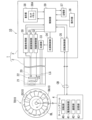
- FIG. 1 is a block diagram showing a configuration of an inspection support system according to a first embodiment of the present invention.
- 1 is a diagram showing a schematic arrangement of rotor blades and stator blades in a turbine according to a first embodiment of the present invention
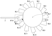
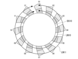
- FIG. 2 is a diagram showing a schematic arrangement of rotor blades in a turbine according to the first embodiment of the present invention.
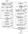
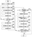
- 4 is a flowchart showing a procedure of processing executed by the endoscope apparatus according to the first embodiment of the present invention.
- 5A to 5C are diagrams illustrating an example of information displayed on a display unit of the endoscope apparatus according to the first embodiment of the present invention.
- FIGS. 5A to 5C are diagrams illustrating an example of information displayed on a display unit of the endoscope apparatus according to the first embodiment of the present invention.
- 4 is a diagram showing an example of examination management information according to the first embodiment of the present invention;
- FIG. 5A to 5C are diagrams illustrating an example of information displayed on a display unit of the endoscope apparatus according to the first embodiment of the present invention.
- 5A to 5C are diagrams illustrating an example of information displayed on a display unit of the endoscope apparatus according to the first embodiment of the present invention.
- 11 is a perspective view of a tip of an insertion portion and a stereo optical adapter in an endoscope apparatus according to a second embodiment of the present invention.
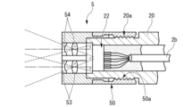
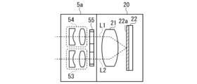
- FIG. 11 is a cross-sectional view of a tip of an insertion portion and a stereo optical adapter in an endoscope apparatus according to a second embodiment of the present invention.
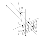
- FIG. 10A to 10C are diagrams illustrating a method for calculating three-dimensional coordinates of a point of interest in the second embodiment of the present invention.
- 10 is a flowchart showing a procedure of processing executed by an endoscope apparatus according to a second embodiment of the present invention.
- 13A to 13C are diagrams illustrating an example of information displayed on a display unit of an endoscope apparatus according to a second embodiment of the present invention.
- 13A to 13C are diagrams illustrating an example of information displayed on a display unit of an endoscope apparatus according to a second embodiment of the present invention.
- 13A to 13C are diagrams illustrating an example of information displayed on a display unit of an endoscope apparatus according to a second embodiment of the present invention.
- FIG. 13 is a cross-sectional view of a tip of an insertion portion and a stereo optical adapter in an endoscope apparatus according to a modified example of the second embodiment of the present invention.
- FIG. FIG. 13 is a diagram showing an observation position of a blade in a third embodiment of the present invention.
- FIG. 13 is a diagram showing an observation position of a blade in a third embodiment of the present invention.
- 10 is a flowchart showing a procedure of a process executed by an endoscope apparatus according to a third embodiment of the present invention.
- 13A to 13C are diagrams showing changes in the position of the field of view of an insertion section of an endoscope device according to a third embodiment of the present invention.
- 13A to 13C are diagrams illustrating an example of information displayed on a display unit of an endoscope apparatus according to a third embodiment of the present invention.
- 10 is a flowchart showing a procedure of a process executed by an endoscope apparatus according to a fourth embodiment of the present invention.
- 10 is a flowchart showing a procedure of a process executed by an endoscope apparatus according to a fourth embodiment of the present invention.
- FIG. 13 is a diagram showing an image of a blade in the fourth embodiment of the present invention.
- 13A to 13C are diagrams illustrating an example of information displayed on a display unit of an endoscope apparatus according to a fourth embodiment of the present invention.
- FIGS. 13A to 13C are diagrams illustrating an example of information displayed on a display unit of an endoscope apparatus according to a fourth embodiment of the present invention.
- 13A to 13C are diagrams illustrating an example of information displayed on a display unit of an endoscope apparatus according to a fourth embodiment of the present invention.
- FIG. 13 is a diagram showing a configuration of an inspection support system according to a fifth embodiment of the present invention.
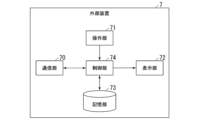
- FIG. 13 is a block diagram showing a configuration of an external device according to a fifth embodiment of the present invention.
- 13 is a flowchart showing a procedure of a process executed by an external device according to a fifth embodiment of the present invention.
- 13 is a flowchart showing a procedure of a process executed by an endoscope apparatus according to a fifth embodiment of the present invention.
- an abnormal area on a blade will simply be referred to as an abnormality.
- FIG. 1 shows the configuration of an inspection support system 10.
- the inspection support system 10 supports the inspection of a turbine TB10, which is an object to be inspected.
- the inspection support system 10 has an endoscope device 1 and a turning tool 4.
- the turbine TB10 has a disk DS10 and two or more blades BL arranged on the circumference of the disk DS10.
- the disk DS10 and the two or more blades BL rotate around a rotation axis RA10.
- the endoscope device 1 captures images of each blade and generates an image.
- the turning tool 4 rotates two or more blades BL by rotating the disk DS10 around the rotation axis RA10.
- the endoscope device 1 has an insertion section 2 and a main body section 3.
- the insertion section 2 is inserted inside the turbine TB10.
- the insertion section 2 is a long, thin tube that is bendable from the tip 20 to the base end.
- the insertion section 2 has a field of view and acquires an optical image of an object within the field of view.
- the object is, for example, a blade BL.
- the insertion section 2 generates an image based on the optical image and outputs the image to the main body section 3.
- An optical adapter is attached to the tip 20.
- a monocular optical adapter is attached to the tip 20.
- the insertion section 2 has a lens section 21, an image sensor 22, and a curved section 23.
- the lens section 21, the image sensor 22, and the curved section 23 are disposed at the tip 20.
- the lens unit 21 is an observation optical system.
- the lens unit 21 has one or more lenses.
- the lens unit 21 captures the optical image formed by the optical adapter.
- the imaging element 22 is an image sensor such as a CCD (Charge-Coupled Device) sensor or a CMOS (Complementary Metal-Oxide-Semiconductor) sensor.
- the imaging element 22 photoelectrically converts the optical image captured by the lens unit 21 and generates an image.
- the imaging element 22 continuously generates two or more images (live images).
- the two or more images form a video.
- the lens unit 21 and the imaging element 22 form a monocular camera with one viewpoint.
- the bending portion 23 bends the insertion portion 2 upward, downward, left, or right.
- the main body 3 is a control device equipped with a storage section for storing the insertion section 2.
- the main body 3 has an image processing section 30, an imaging control section 31, a bending control section 32, a light source section 33, a light source control section 34, a rotation control section 35, an operation section 36, a memory section 37, a display section 38, and a control section 39.
- the image processing unit 30 performs image processing on the image output from the imaging element 22.
- the image processing includes color reproduction, tone correction, noise suppression, and edge enhancement.
- the imaging control unit 31 controls the imaging element 22.
- the bending control unit 32 controls the bending state of the insertion unit 2.
- the bending control unit 32 controls the UD motor and LR motor, which are not shown in FIG. 1.
- the UD motor is connected to a UD bending wire for bending the bending unit 23 upward or downward.
- the UD motor bends the bending unit 23 upward or downward by pulling the UD bending wire.
- the LR motor is connected to an LR bending wire for bending the bending unit 23 left or right.
- the LR motor bends the bending unit 23 left or right by pulling the LR bending wire.
- the light source unit 33 has a light source such as an LED (Light-Emitting Diode) and generates illumination light.
- the illumination light is guided to the tip 20 via a light guide LG arranged in the insertion section 2.
- the illumination light is irradiated from the tip 20 to the inside of the turbine TB10.
- the light source control unit 34 controls the light source unit 33.
- the rotation control unit 35 generates a rotation control signal for controlling the turning tool 4, and transmits the rotation control signal to the turning tool 4.
- the rotation control unit 35 also receives rotation information transmitted from the turning tool 4, and outputs the rotation information to the control unit 39.
- the rotation information indicates the amount of rotation (rotation angle) of the disk DS10.
- the amount of rotation is not limited to the rotation angle, and may be any information that indicates the degree of rotation.
- the amount of rotation may be the number of motor steps, or the number of blades from a reference blade, which will be described later.
- the operation unit 36 is a user interface.
- the operation unit 36 is at least one of a button, a switch, a key, a mouse, a joystick, a touchpad, a trackball, and a touch panel.
- the operation unit 36 accepts operations on the endoscope device 1 from the user. The user can input various information to the endoscope device 1 by operating the operation unit 36.
- the memory unit 37 is a volatile or non-volatile recording medium.
- the memory unit 37 is at least one of a RAM (Random Access Memory), a DRAM (Dynamic Random Access Memory), a SRAM (Static Random Access Memory), a ROM (Read Only Memory), an EPROM (Erasable Programmable Read Only Memory), an EEPROM (Electrically Erasable Programmable Read-Only Memory), a flash memory, a HDD (Hard Disk Drive), and a SSD (Solid State Drive).
- the storage unit 37 stores images and the like.
- the storage unit 37 may be detachable from the endoscope device 1.
- the storage unit 37 may be a recording medium included in an external device such as a cloud server.
- the display unit 38 is a monitor (display) such as an LCD (Liquid Crystal Display).
- the display unit 38 has a display screen and displays images, operation menus, etc. on the display screen.
- the display unit 38 has a touch panel 38A.
- the user can input various information to the endoscope device 1 by touching the touch panel 38A.
- the control unit 39 controls the operation of the endoscope device 1 based on a program stored in the endoscope device 1.
- the program executed by the control unit 39 may be recorded on a computer-readable recording medium.
- the program recorded on this recording medium may be read and executed by a computer other than the endoscope device 1.
- At least one of the image processing unit 30, the imaging control unit 31, the curvature control unit 32, the light source control unit 34, the rotation control unit 35, and the control unit 39 may be composed of at least one of a processor and a logic circuit.
- the processor is at least one of a CPU (Central Processing Unit), a DSP (Digital Signal Processor), and a GPU (Graphics Processing Unit).
- the logic circuit is at least one of an ASIC (Application Specific Integrated Circuit) and an FPGA (Field-Programmable Gate Array).
- At least one of the image processing unit 30, the imaging control unit 31, the bending control unit 32, the light source control unit 34, the rotation control unit 35, and the control unit 39 can include one or more processors.
- At least one of the image processing unit 30, the imaging control unit 31, the bending control unit 32, the light source control unit 34, the rotation control unit 35, and the control unit 39 can include one or more logic circuits.
- the above program may be provided by a "computer-readable recording medium” such as a flash memory.
- the program may be transmitted from a computer that holds the program to the endoscope device 1 via a transmission medium, or by a transmission wave in the transmission medium.
- the "transmission medium” that transmits the program is a medium that has the function of transmitting information.
- Media that have the function of transmitting information include networks (communication networks) such as the Internet and communication lines (communication lines) such as telephone lines.
- the above program may realize some of the functions described above.
- the above program may be a difference file (difference program).
- the functions described above may be realized by combining a program already recorded in the computer with a difference program.
- the turning tool 4 is connected to the rotation control unit 35 of the main body 3 via a cable CB.
- the turning tool 4 has a rotation unit 40, a drive control unit 41, a communication unit 42, and a memory unit 43.
- the storage unit 43 is a recording medium such as a memory card.
- the storage unit 43 may be detachable from the turning tool 4.
- the storage unit 43 stores the specimen information including the number of blades arranged on the disk DS10.
- the communication unit 42 reads out the specimen information from the storage unit 43 and transmits the specimen information to the rotation control unit 35.
- a remote control may be used to control the turning tool 4.
- a user may control the turning tool 4 by operating the remote control.
- the insertion section 2 and the control section 39 constitute an imaging device (camera).
- the imaging element 22 may be disposed in the main body section 3, and an optical fiber may be disposed in the insertion section 2. Light incident on the lens section 21 may reach the imaging element 22 through the optical fiber.
- a borescope may be used as a camera.
- Turbines are used in aircraft engines or generators. There are gas turbines and steam turbines. The structure of a gas turbine is explained below. In the following, gas turbines will be referred to as turbines.
- FIG. 2 shows a schematic arrangement of rotor blades and stator vanes in the compression section of turbine TB10.
- FIG. 2 shows a portion of a cross section of turbine TB10 passing through rotation axis RA10.
- Turbine TB10 has rotor blade RT10, stator vane ST10, rotor blade RT11, stator vane ST11, rotor blade RT12, stator vane ST12, rotor blade RT13, and stator vane ST13 in the compression section. These rotor blades rotate around rotation axis RA10 in direction DR12.
- Rotor blade RT10 is located in the low pressure section that takes in air.
- Rotor blade RT13 is located in the high pressure section that expels air.
- Access port AP10 is formed to enable inspection of the inside of turbine TB10 without disassembling turbine TB10.
- Turbine TB10 has two or more access ports, one of which is shown in FIG. 2 as access port AP10.
- Access port AP10 is a hole formed in turbine TB10.
- the insertion portion 2 constitutes an endoscope.
- the insertion portion 2 is inserted into the turbine TB10 through the access port AP10.
- the insertion portion 2 moves in a direction DR10.
- the insertion portion 2 moves in a direction opposite to the direction DR10.
- the direction DR10 is different from the direction DR12.
- the direction DR10 extends in the longitudinal direction of the insertion portion 2.
- Illumination light LT10 is emitted from the tip 20 of the insertion portion 2.
- the turning tool 4 rotates the disk DS10, or the user manually rotates the disk DS10.
- the user inspects the blades BL1 to BL12 and determines whether there are any abnormalities in each blade. This inspection is one of the main inspection items in turbine inspection.
- the mark MK10 may be formed near the reference blade.
- the inspection procedure may specify that the blade BL1 closest to the mark MK10 is set as the reference blade.
- the user can determine that the blade BL1 near the mark MK10 is the reference blade.
- the insertion unit 2 captures the reference blade within the field of view VF10, the turning tool 4 or the user stops the rotation of the disk DS10. The user adjusts the position and attitude of the tip 20 to properly observe the blade BL1.
- tip 20 After the position and orientation of tip 20 have been adjusted, tip 20 is fixed. Then, the inspection begins.
- a turning tool rotates the disk so that the insertion part can obtain an optical image of the blade.
- the turning tool stops the rotation of the disk. The user adjusts the position and attitude of the insertion part, the illumination light condition, the state of the optical system, etc. as necessary.
- the user closely examines the image of the blade produced by the insert and performs an inspection of the blade.
- the above steps and processes are repeated to inspect two or more blades in sequence.
- the disk DS10 rotates so that the insertion unit 2 can capture the blade within its field of view. After the rotation of the disk DS10 stops, the insertion unit 2 generates a first image of the blade. After the insertion unit 2 has generated all of the first images of the two or more blades BL, the first images are used to perform a simple inspection (screening) of all of the two or more blades BL. In the screening, it is determined whether or not observation (detailed observation) of each blade is necessary.
- the disk DS10 rotates so that the inserter 2 can capture the blade that requires detailed observation within its field of view. After the rotation of the disk DS10 stops, the inserter 2 generates a second image of the blade. A detailed inspection of the blade is performed using the second image.
- FIG. 4 shows the procedure of the process executed by the endoscope device 1.
- the user completes the tasks required to start the examination. For example, the user opens the access port AP10, inserts the insertion portion 2 from the access port AP10 into the turbine TB10, and moves the tip 20 to the destination where the examination will begin.
- the imaging element 22 sequentially generates two or more images (live images).
- the image processing unit 30 performs image processing on each image.
- the control unit 39 acquires the image processed by the image processing unit 30 and displays the image on the display unit 38. Each time the imaging element 22 generates a new image, the control unit 39 displays the image on the display unit 38.
- control unit 39 executes the following process to capture the reference blade within the field of view of the insertion unit 2 (step S100).
- the control unit 39 outputs rotation control information for rotating the disk DS10 to the rotation control unit 35.
- the rotation control unit 35 generates a rotation control signal according to the rotation control information and transmits the rotation control signal to the turning tool 4.
- the communication unit 42 of the turning tool 4 receives the rotation control signal.
- the drive control unit 41 controls the rotation unit 40 according to the rotation control signal.
- the rotation unit 40 rotates the disk DS10.
- the rotation unit 40 stops the rotation of the disk DS10.
- the disk DS10 comes to a standstill.
- the reference blade is located in the center of the field of view.
- the manufacturer of a particular turbine defines the reference blades, or the reference blades are defined for a particular type of turbine. In such cases, a readily visible mark is made in the turbine so that the user can easily find the reference blades.
- a specific blade with a characteristic pattern on its surface or edge is set as the reference blade.
- a user sets a specific blade as the reference blade.
- the image processing unit 30 processes the image generated by the imaging element 22 and detects the characteristic pattern.
- the control unit 39 sets the blade with that pattern as the reference blade.
- the control unit 39 also displays information on the display unit 38 indicating that a blade suitable for the reference blade has been found. Any method may be used to set the reference blade.
- the user When a reference blade has been defined, the user observes the image displayed on the display unit 38 and finds the reference blade. At this time, the user operates the operation unit 36 or the touch panel 38A to input an instruction to the endoscope device 1 to stop the rotation of the disk DS10.
- the control unit 39 outputs rotation control information for stopping the rotation of the disk DS10 to the rotation control unit 35.
- the same process as described above is executed, and the drive control unit 41 controls the rotation unit 40 according to the rotation control signal.
- the rotation unit 40 stops the rotation of the disk DS10.
- the disk DS10 comes to a standstill.
- the control unit 39 outputs rotation control information to the rotation control unit 35 to stop the rotation of the disk DS10, regardless of instructions from the user. Specifically, the control unit 39 outputs rotation control information to the rotation control unit 35 at the timing when a characteristic pattern is detected. The same process as described above is executed, and the drive control unit 41 controls the rotation unit 40 according to the rotation control signal. The rotation unit 40 stops the rotation of the disk DS10. The disk DS10 comes to a standstill.
- control unit 39 executes the following process to capture the target blade to be observed within the field of view of the insertion unit 2 (step S101).
- the rotation control unit 35 receives the specimen information sent from the turning tool 4, and outputs the specimen information to the control unit 39.
- the specimen information includes the number of blades arranged on the disk DS10.
- the control unit 39 calculates the angle between two adjacent blades based on that number.
- the control unit 39 outputs rotation control information to the rotation control unit 35 for rotating the disk DS10 by that angle.
- the same process as described above is executed, and the drive control unit 41 controls the rotation unit 40 according to the rotation control signal.
- the rotation unit 40 rotates the disk DS10 by that angle.
- the user may rotate the disk DS10 manually.
- the user may rotate the disk DS10 by operating a remote control.
- the user may observe the image displayed on the display unit 38 and stop the rotation of the disk DS10 when the target blade is captured within the field of view of the insertion unit 2.
- the control unit 39 has a counter therein.
- the initial value of the counter is 0.
- the control unit 39 increments the counter value by 1. The value indicates the blade number.
- the memory unit 37 stores the inspection management information including various information related to the inspection.
- the control unit 39 adds the blade number to the inspection management information. Details of the inspection management information will be described later with reference to FIG. 7.
- control unit 39 acquires the image processed by the image processing unit 30 and stores the image in the storage unit 37 as a first image.
- the control unit 39 also adds the number (file name) of the first image to the examination management information (step S102).
- control unit 39 may perform feedback control to fine-tune the rotation of the disk DS10, and stop the target blade at the target position.
- the control unit 39 may execute the following feedback control.
- the control unit 39 extracts the area of the blade in the first image, and judges whether or not the area is in the center of the first image. When the area is shifted from the center of the first image, the control unit 39 outputs rotation control information to the rotation control unit 35 for slightly rotating the disk DS10. A process similar to that described above is executed, and the drive control unit 41 controls the rotation unit 40 according to the rotation control signal.
- the rotation unit 40 rotates the disk DS10 slightly.
- the threshold value set to stop the rotation of the disk DS10 may have a wide range. If the target blade exceeds the target position, the control unit 39 may also execute control similar to the feedback control described above.
- control unit 39 acquires the image processed by the image processing unit 30 as a first image.
- the control unit 39 stores the first image in the storage unit 37.
- the feedback control changes the relative position or posture of the blade with respect to the insertion unit 2.
- the control unit 39 sets the first shooting conditions. For example, the control unit 39 executes the following process.
- the control unit 39 sets the bending state of the insertion unit 2 as the first imaging condition. Specifically, the control unit 39 outputs bending control information for controlling the bending state of the insertion unit 2 to the bending control unit 32.
- the bending control unit 32 bends the bending unit 23 in accordance with the bending control information, and sets the position and attitude of the image sensor 22 to a predetermined position and attitude.
- the control unit 39 sets the position of the insertion portion 2 as the first imaging condition. Specifically, the control unit 39 outputs control information for controlling the position of the insertion portion 2 to the insertion device.
- the insertion device moves the insertion portion 2 and sets the position of the insertion portion 2 to a predetermined position. As a result, the insertion device sets the position of the image sensor 22 to a predetermined position.
- the control unit 39 sets the attitude of the insertion unit 2 as the first imaging condition. Specifically, the control unit 39 outputs control information to the insertion device for controlling the rotation angle of the insertion unit 2 around an axis extending in the longitudinal direction of the insertion unit 2. The insertion device twists the insertion unit 2 and sets the rotation angle of the insertion unit 2 to a predetermined angle. As a result, the insertion device sets the attitude of the image sensor 22 to the predetermined attitude.
- the control unit 39 sets the position and attitude of the blade captured in the field of view of the insertion unit 2 as the first imaging condition. Specifically, the control unit 39 controls the turning tool 4 by executing control similar to the feedback control described above.
- the turning tool 4 rotates the disk DS10 and sets the position of the blade captured in the field of view of the insertion unit 2 to a predetermined position. In other words, the turning tool 4 sets the relative position of the imaging element 22 with respect to the blade to a predetermined position.
- the turning tool 4 rotates the disk DS10 and sets the posture of the blade captured in the field of view of the insertion part 2 to a predetermined posture. In other words, the turning tool 4 sets the relative posture of the imaging element 22 with respect to the blade to a predetermined posture.
- the control unit 39 sets the imaging parameters of the image sensor 22 as the first shooting condition. Specifically, the control unit 39 outputs imaging control information for setting the imaging parameters of the image sensor 22 to the imaging control unit 31.
- the imaging control unit 31 controls the image sensor 22 in accordance with the imaging control information. For example, the imaging control unit 31 sets the exposure time of the image sensor 22 to a predetermined value, or sets the gain of the image sensor 22 to a predetermined value.
- the control unit 39 sets the state of the illumination light generated by the light source unit 33 as the first shooting condition. Specifically, the control unit 39 outputs light source control information for controlling the state of the illumination light to the light source control unit 34.
- the light source control unit 34 controls the light source unit 33 in accordance with the light source control information, and sets the brightness of the illumination light to a predetermined brightness.
- the control unit 39 sets the parameters of the image processing executed by the image processing unit 30 as the first shooting condition. Specifically, the control unit 39 sets the strength of noise suppression or edge enhancement to a predetermined strength.
- the control unit 39 sets the state of the lens unit 21 as the first shooting condition. Specifically, the control unit 39 sets the zoom state of the lens unit 21 to a wide state, or sets the focus state of the lens unit 21 to a far point.
- the control unit 39 sets one or more of the position of the imaging element 22, the attitude of the imaging element 22, the relative position of the imaging element 22 with respect to the blade captured in the field of view of the insertion unit 2, the relative attitude of the imaging element 22 with respect to the blade, the imaging parameters of the imaging element 22, the state of the illumination light, the parameters of the image processing, and the state of the lens unit 21.
- the user may input an instruction to set the first imaging condition to the endoscope device 1 by operating the operation unit 36 or the touch panel 38A.
- the instruction is, for example, a curvature instruction.
- the control unit 39 may set the first imaging condition according to the instruction.
- the control unit 39 may add the first imaging condition to the examination management information.
- the user may manually move the insertion portion 2 in the longitudinal direction (axial direction) of the insertion portion 2 to set the first imaging condition.
- the user may manually twist the insertion portion 2.
- the first shooting conditions may be fixed while the image sensor 22 generates two or more images that are captured as the first image.
- control unit 39 acquires the rotation information and stores the rotation information in the storage unit 37 (step S103).
- the control unit 39 outputs control information for acquiring rotation information to the rotation control unit 35.
- the rotation control unit 35 generates an information acquisition signal according to the control information, and transmits the information acquisition signal to the turning tool 4.
- the communication unit 42 of the turning tool 4 receives the information acquisition signal.
- the drive control unit 41 generates rotation information indicating the amount of rotation (rotation angle) required to rotate the disk DS10 from the first position to the second position.
- the first position indicates the position of the disk DS10 when the insertion unit 2 acquires the optical image of the reference blade.
- the second position indicates the position of the disk DS10 after step S101 is executed.
- the rotation information indicates the angle between the reference blade and the target blade.
- the communication unit 42 transmits the rotation information to the rotation control unit 35.
- the rotation control unit 35 receives the rotation information and outputs the rotation information to the control unit 39.
- the control unit 39 stores the rotation information in the memory unit 37. At this time, the control unit 39 associates the rotation information with the first image acquired in step S102. By using the rotation information, the endoscope device 1 can rotate the disk DS10 so that the insertion unit 2 can acquire an optical image of a specific blade again.
- the first image may include rotation information.
- the rotation information may be included in an Exif (Exchangeable Image File Format) area of the first image.
- the rotation information may be included in a file different from the file containing the first image, and the rotation information and the first image may be associated with each other.
- control unit 39 adds the rotation information to the examination management information.
- the rotation information and the first image are associated with each other.
- control unit 39 determines whether the first images of all blades have been acquired (step S104).
- the control unit 39 acquires the counter value. As described above, the value indicates the blade number. As described above, the specimen information includes the number of blades arranged on the disk DS10. The control unit 39 determines whether the number indicated by the specimen information is the same as the blade number. When the number indicated by the specimen information is the same as the blade number, the control unit 39 determines that first images of all blades have been acquired. When the number indicated by the specimen information is greater than the blade number, the control unit 39 determines that first images of some of the blades arranged on the disk DS10 have not been acquired.
- the user knows in advance the number of blades arranged on the disk DS10.
- the user may input this number into the endoscope device 1 by operating the operation unit 36 or the touch panel 38A.
- step S101 is executed.
- the insertion unit 2 captures within its field of view a blade adjacent to the blade captured within its field of view immediately before step S104 is executed.
- the turbine TB10 has two or more blades BL. Therefore, the memory unit 37 stores two or more first images. Typically, several tens to approximately two hundred blades are arranged on the disk. That is, steps S101 to S104 are repeated more than several tens of times.
- the endoscope device 1 may obtain two or more first images of the same blade. Therefore, the number of first images and the number of blades are not always the same.
- the control unit 39 may skip acquiring the first image for some of the two or more blades BL.
- control unit 39 may display the blade number on the display unit 38. The user can know which blade is currently being observed.
- control unit 39 determines in step S104 that the first images of all blades have been acquired, the control unit 39 displays two or more first images stored in the memory unit 37 on the display unit 38 (step S105).
- FIG. 5 shows an example of information displayed on the display unit 38 in step S105.
- the control unit 39 displays the dialog box DB10 shown in FIG. 5 on the display unit 38.
- the dialog box DB10 has a first region R1 and a second region R2.
- a first image IMG10 is displayed in the first region R1.
- the first image IMG10 is highlighted so that the user can easily view the first image IMG10. For example, the first image IMG10 is enlarged.
- Additional information IF10 is displayed on the first image IMG10.
- additional information IF10 includes a blade number.
- Additional information IF10 may include a file name of the first image IMG10.
- additional information IF10 may include coordinates or pixel values (RGB values) of a particular pixel of the first image IMG10.
- the first images IMG1 to IMG4 and blade numbers "01" to "04" are displayed in the second region R2.
- Each of the first images IMG1 to IMG4 is a thumbnail image of the first image acquired in step S102.
- a list of the first images IMG1 to IMG4 may be displayed in the second region R2.
- the blades appearing in each of the first images IMG1 to IMG4 have blade numbers. For example, the blade appearing in the first image IMG1 has blade number "01".
- the first image IMG10 in the first region R1 corresponds to the first image IMG1 in the second region R2.
- the frame of the first image IMG1 is highlighted to inform the user that the first image IMG10 corresponds to the first image IMG1.
- First images IMG2 to IMG4 are not displayed in the first region R1.
- the user can view first images IMG2 to IMG4 that are not displayed in the first region R1.
- the user can select one of the first images IMG1 to IMG4 by operating the operation unit 36 or the touch panel 38A. When one first image is selected, that first image is displayed in the first region R1.
- part of the second region R2 is displayed within the dialog box DB10.
- the second region R2 outside the dialog box DB10 is not displayed.
- the user can move the scroll bar SB10 by operating the operation unit 36 or the touch panel 38A.
- the scroll bar SB10 is moved, the second region R2 outside the dialog box DB10 moves into the dialog box DB10 and is displayed.
- the scroll bar SB10 may be used to change the first image displayed in the first region R1.
- the first image IMG2 may be displayed in the first region R1 instead of the first image IMG10.
- the control unit 39 may store a video including two or more images generated by the image sensor 22 in the storage unit 37 as a first image.
- the control unit 39 may display a specific image (frame) included in the video on the display unit 38 in step S105.
- the user observes two or more first images displayed on the display unit 38.
- the user judges the condition of the blades shown in each of the first images.
- the user inputs the result of the judgment to the endoscope device 1 by operating the operation unit 36 or the touch panel 38A.
- the control unit 39 generates status information according to the result of the judgment.
- the status information indicates the condition of the blades shown in each of the first images.
- the status information includes observation information indicating whether or not detailed observation of each blade is required.
- the control unit 39 adds the status information to the first images (step S106).
- the type of abnormality and the conditions for passing or failing the inspection are described in the inspection manual.
- the conditions relate to the size of the abnormality.
- the user judges the condition of the blade shown in each first image according to the contents of the inspection manual. When the user finds an area that may be abnormal, he or she determines that a detailed observation is necessary.
- the first image may include state information.
- the state information may be included in an Exif area of the first image.
- the state information may be included in a file that is different from the file that includes the first image, and the state information and the first image may be associated with each other.
- control unit 39 adds the status information to the examination management information.
- the status information and the first image are associated with each other.
- the status information may include information indicating OK or NG in addition to the observation information.
- the user may input information indicating OK to the endoscope device 1, and the status information may include information indicating OK.
- the status information may include observation information indicating that detailed observation is not necessary.
- the user may input information indicating NG to the endoscope device 1, and the status information may include information indicating NG.
- the status information may include observation information indicating that detailed observation is necessary.
- the user may input information to the endoscope device 1 indicating that an abnormality exists and that follow-up observation is required, and the status information may include such information.
- the user may input information to the endoscope device 1 indicating that an abnormality exists and that the severity is low, and the status information may include such information.
- Status information regarding an acceptable abnormality may include observation information indicating that detailed observation is not required.
- Observation information may be represented as a value indicating confidence or severity (e.g., a percentage) instead of a binary (Boolean) value indicating true or false.
- the user taps on any one of the first images IMG1 to IMG4 and the first image IMG10 displayed in the dialog box DB10 shown in FIG. 5 by operating the operation unit 36 or the touch panel 38A.
- the control unit 39 selects the tapped first image and displays a dialog box different from the dialog box DB10 on the display unit 38. Two or more candidates for the status information are displayed in the dialog box.
- the user operates the operation unit 36 or the touch panel 38A to input an instruction to the endoscope device 1 to select one of two or more candidates.
- the control unit 39 adds status information corresponding to the candidate indicated by the instruction to the tapped first image.
- the control unit 39 displays the dialog box DB10 shown in FIG. 5 again.
- the user can add status information to all of the two or more first images displayed on the display unit 38 by repeating the above operations.
- the user may determine the status of only some of the two or more blades BL.
- the control unit 39 may determine that the blades whose status is not selected by the user are healthy (OK).
- the user may input an instruction to change the status information to the endoscope device 1 by operating the operation unit 36 or the touch panel 38A.
- the control unit 39 may change the status information based on the instruction.
- control unit 39 may process the first image and determine the state of the blade.
- control unit 39 displays the status information on the display unit 38 (step S107).
- FIG. 6 shows an example of information displayed on the display unit 38 in step S107.
- the control unit 39 displays the dialog box DB11 shown in FIG. 6 on the display unit 38. Explanation of the same parts as those shown in FIG. 5 will be omitted.
- Status information SI10 is displayed on the first image IMG10.
- the status information SI10 is added to the first image IMG10.
- Status information SI1 to SI4 are displayed in the second region R2.
- One of the status information SI1 to SI4 is added to one of the first images IMG1 to IMG4.
- status information SI1 is added to the first image IMG1.
- the first image IMG10 in the first region R1 corresponds to the first image IMG1 in the second region R2. Therefore, the status information SI10 added to the first image IMG10 corresponds to the status information SI1 added to the first image IMG1.
- status information SI10 and status information SI1 to SI4 are displayed in a color that corresponds to the status of the blade.
- status information SI10, SI1, and SI4 indicate that there is no abnormality in the blades shown in the first images IMG10, IMG1, and IMG4.
- status information SI2 indicates that the blade shown in the first image IMG2 requires closer observation.
- status information SI3 indicates that the blade shown in the first image IMG3 is in a high severity state.
- the status information SI10 and the status information SI1 to SI4 may be displayed as characters indicating the status of the blade.
- the status information SI10 and the status information SI1 to SI4 may be displayed as a graphic having a shape corresponding to the status of the blade.
- the blade number may be displayed in a color corresponding to the status of the blade. Any method may be used to display the status information SI10 and the status information SI1 to SI4 as long as the user can recognize the status of the blade.
- a button BT10 is displayed in the first region R1.
- the user can press the button BT10 by operating the operation unit 36 or the touch panel 38A.
- the control unit 39 may process each of the two or more first images displayed on the display unit 38 and determine the state of the blade depicted in each of the first images.
- the control unit 39 may generate status information according to the result of the determination, and may add the status information to each of the first images.
- the control unit 39 may generate the status information by using the first image in step S106. Details of this process will be described below. A first example and a second example will be described below. In these examples, the control unit 39 does not need to display the first image on the display unit 38 in step S105.
- the memory unit 37 pre-stores a reference image showing an abnormality.
- the control unit 39 acquires the reference image from the memory unit 37 and compares the reference image with the first image. Specifically, the control unit 39 executes a matching process and determines whether the blade shown in the first image includes an area similar to the abnormality shown in the reference image. When the control unit 39 determines that the blade includes that area, the control unit 39 generates status information including observation information indicating that detailed observation of the blade is required. When the control unit 39 determines that the blade does not include that area, the control unit 39 generates status information including observation information indicating that detailed observation of the blade is not required.
- the memory unit 37 pre-stores feature information indicating the features of the abnormality.
- the feature information is generated by using images acquired in a previously performed inspection.
- the feature information indicates features such as the color, size, and shape of the abnormality.
- the control unit 39 judges whether the features of the blade shown in the first image are similar to the features of the abnormality indicated by the feature information. When the control unit 39 judges that the features of the blade are similar to the features of the abnormality indicated by the feature information, the control unit 39 generates status information including observation information indicating that detailed observation of the blade is required. When the control unit 39 judges that the features of the blade are not similar to the features of the abnormality indicated by the feature information, the control unit 39 generates status information including observation information indicating that detailed observation of the blade is not required.
- machine learning may be used.
- deep learning may be used as machine learning.
- a user observes an image acquired in a previously performed examination and judges whether an area shown in the image is abnormal or normal.
- the control unit 39 uses the image and correct answer data (teacher data) indicating the result of the user's judgment to analyze the features of the image and generate a trained model.
- the trained model corresponds to the feature information.
- the memory unit 37 stores the trained model.
- control unit 39 After the first image is acquired, the control unit 39 inputs the first image into the trained model and acquires as output information indicating whether the area shown in the first image is abnormal or normal. Based on that information, the control unit 39 generates status information including observation information.
- the blades in the images used to generate the feature information do not have to be the same as the blades in the first image.
- the feature information may be generated from an image showing blades of a turbine different from the turbine whose blades are in the first image.
- the control unit 39 may calculate a value indicating reliability or severity by using the reference image or feature information.
- the control unit 39 may determine whether the blade shown in the first image is abnormal or not based on the value, and generate status information.
- the range of reliability or severity values corresponding to the abnormality may be changeable depending on the purpose of the inspection.
- control unit 39 determines whether detailed observation of one or more blades is required (step S108).
- the control unit 39 acquires the status information added to each first image from the storage unit 37.
- the control unit 39 refers to the observation information included in the status information. When the observation information indicates that detailed observation is necessary, the control unit 39 determines that detailed observation of the blade shown in that first image is necessary. When the observation information indicates that detailed observation is not necessary, the control unit 39 determines that detailed observation of the blade shown in that first image is not necessary.
- the control unit 39 executes the above process for all first images to which status information has been added.
- control unit 39 determines that detailed observation is unnecessary. If there is an image with observation information added indicating that detailed observation is necessary, the control unit 39 determines that detailed observation is necessary.
- step S108 determines in step S108 that detailed observation is not required
- the process shown in FIG. 4 ends.
- the control unit 39 selects all first images to which observation information indicating that detailed observation is required is added, and determines the order of detailed observation of the blades shown in the first images (step S109).
- step S109 Details of step S109 will be described. If the status information includes a value indicating reliability or seriousness, the control unit 39 determines the order of detailed observation based on that value. For example, the blades are observed in descending order of seriousness according to that order. Alternatively, the control unit 39 determines the order of detailed observation based on the position of the blade that requires detailed observation. For example, the blades are observed clockwise or counterclockwise from the reference blade according to that order. The user may input information indicating the order of detailed observation to the endoscope device 1 by operating the operation unit 36 or touch panel 38A. Any method may be used to determine the order of detailed observation.
- control unit 39 determines that detailed observation will be performed only on the blade shown in that first image.
- the control unit 39 adds information indicating the order of detailed observation to the inspection management information.
- status information SI2 indicates that detailed observation of the blade shown in the first image IMG2 is required.
- the blade number of that blade is 2.
- Status information other than status information SI2 indicates that detailed observation of the blade shown in the first image to which that status information is attached is not required. Therefore, detailed observation of only the blade shown in the first image IMG2 is performed.
- the number "1" indicating the order of detailed observation of that blade is displayed on the first image IMG2 (not shown).
- FIG. 7 shows an example of inspection management information stored in the memory unit 37.
- the inspection management information MNG10 shown in FIG. 7 includes the blade number, image number, status information, reliability, type of abnormality, severity, rotation information, and order of detailed observation. These are associated with each other.
- the control unit 39 adds the blade number to the inspection management information in step S101.
- the control unit 39 adds the image number to the inspection management information in step S102. Two or more first images of the same blade may be acquired. In the example shown in FIG. 7, the control unit 39 acquires two first images of the blade having the blade number "003", and acquires two first images of the blade having the blade number "006".
- the control unit 39 adds the rotation information to the inspection management information in step S103.
- the rotation information is shown as the position of each blade.
- the control unit 39 adds the status information, reliability, type of abnormality, and severity to the inspection management information in step S106.
- the control unit 39 adds the order of detailed observation to the inspection management information in step S109.
- the status information of the blade with blade number "003" and the status information of the blade with blade number "007” indicate that detailed observation is required.
- the order of detailed observation indicates that the blade with blade number "003" and the blade with blade number "007” will be observed in that order.
- control unit 39 executes the following process to capture the blade that requires detailed observation within the field of view of the insertion unit 2 (step S110).
- the control unit 39 selects the target blade according to the order determined in step S109.
- the control unit 39 acquires the rotation information added to the first image in which the selected target blade appears from the storage unit 37.
- the control unit 39 acquires the rotation information associated with the blade number of the target blade from the inspection management information.
- the control unit 39 calculates the amount of rotation (rotation angle) of the disk DS10 required to capture the target blade within the field of view of the insertion unit 2.
- the current amount of rotation of the disk DS10 is 0 degrees
- the reference blade is captured within the field of view of the insertion unit 2.
- the current amount of rotation of the disk DS10 is N degrees (0 ⁇ N ⁇ 360).
- the angle indicated by the rotation information is 120 degrees, in order to capture the target blade within the field of view of the insertion unit 2, it is necessary to rotate the disk DS10 by (120-N) degrees.
- the control unit 39 outputs rotation control information to the rotation control unit 35 for rotating the disk DS10 by the above angle.
- the same process as described above is executed, and the drive control unit 41 controls the rotation unit 40 according to the rotation control signal.
- the rotation unit 40 rotates the disk DS10 by that angle. After the disk DS10 has rotated by that angle, the rotation unit 40 stops the rotation of the disk DS10.
- the disk DS10 comes to a standstill.
- the insertion unit 2 captures the target blade within its field of view and acquires an optical image of the target blade.
- control unit 39 may display on the display unit 38 the total number of blades that require detailed observation and the number of blades for which detailed observation has been completed. For example, if detailed observation of five blades is required and detailed observation of two blades has been completed, the control unit 39 will display "2/5" on the display unit 38.
- control unit 39 acquires the image processed by the image processing unit 30 as a second image, and stores the second image in the memory unit 37 (step S111).
- control unit 39 displays two or more live images generated by the image sensor 22 on the display unit 38.
- the live images include a second image.
- the control unit 39 sets a second imaging condition.
- the second imaging condition is one or more of the position of the image capturing element 22, the attitude of the image capturing element 22, the relative position of the image capturing element 22 with respect to the blade captured in the field of view of the insertion unit 2, the relative attitude of the image capturing element 22 with respect to the blade, the imaging parameters of the image capturing element 22, the state of the illumination light, the parameters of the image processing, and the state of the lens unit 21.
- the user needs to determine whether the blade condition is OK or NG. Therefore, the user determines whether the blade condition is OK or NG in detailed observation. If the second shooting conditions are the same as the first shooting conditions, the condition of the blade shown in the second image is similar to the condition of the blade shown in the first image. In such a case, it is difficult for the user to determine that the blade condition is different from the condition that requires detailed observation.
- the control unit 39 executes the following process to make the second shooting conditions different from the first shooting conditions.
- the control unit 39 sets the curved state of the insertion unit 2 as the second shooting condition.
- the control unit 39 executes a process similar to the process for setting the first shooting condition, and sets the position and attitude of the image sensor 22 to a predetermined position and attitude.
- the position of the image sensor 22 set as the second shooting condition is different from the position of the image sensor 22 set as the first shooting condition.
- the attitude of the image sensor 22 set as the second shooting condition is different from the attitude of the image sensor 22 set as the first shooting condition.
- the control unit 39 sets the position of the insertion unit 2 as the second shooting condition.
- the control unit 39 executes a process similar to the process for setting the first shooting condition, and sets the position of the image sensor 22 to a predetermined position.
- the position of the image sensor 22 set as the second shooting condition is different from the position of the image sensor 22 set as the first shooting condition.
- the control unit 39 sets the attitude of the insertion unit 2 as the second shooting condition.
- the control unit 39 executes a process similar to the process for setting the first shooting condition, and sets the attitude of the image sensor 22 to a predetermined attitude.
- the attitude of the image sensor 22 set as the second shooting condition is different from the attitude of the image sensor 22 set as the first shooting condition.
- the control unit 39 sets the position and posture of the blade captured in the field of view of the insertion unit 2 as the second shooting condition.
- the control unit 39 executes a process similar to the process for setting the first shooting condition, and sets the position of the blade to a predetermined position. In other words, the control unit 39 sets the relative position of the image sensor 22 with respect to the blade to a predetermined position.
- the relative position of the image sensor 22 set as the second shooting condition is different from the relative position of the image sensor 22 set as the first shooting condition.
- the control unit 39 also executes a process similar to the process for setting the first imaging condition, and sets the attitude of the blade captured in the field of view of the insertion unit 2 to a predetermined attitude. In other words, the control unit 39 sets the relative attitude of the image sensor 22 with respect to the blade to a predetermined attitude.
- the relative attitude of the image sensor 22 set as the second imaging condition is different from the relative attitude of the image sensor 22 set as the first imaging condition.
- the control unit 39 sets the imaging parameters of the image sensor 22 as the second shooting condition.
- the control unit 39 executes a process similar to the process for setting the first shooting condition, and sets the exposure time of the image sensor 22 to a predetermined value.
- the exposure time set as the second shooting condition is longer than the exposure time set as the first shooting condition.
- the control unit 39 sets the gain of the image sensor 22 to a predetermined value.
- the gain set as the second shooting condition is greater than the gain set as the first shooting condition.
- the control unit 39 sets the state of the illumination light generated by the light source unit 33 as the second shooting condition.
- the control unit 39 executes a process similar to the process for setting the first shooting condition, and sets the brightness of the illumination light to a predetermined brightness. For example, the illumination light in the second shooting condition is brighter than the illumination light in the first shooting condition.
- the control unit 39 sets the parameters of the image processing executed by the image processing unit 30 as the second shooting conditions. Specifically, the control unit 39 sets the strength of noise suppression or edge enhancement to a predetermined strength. For example, the control unit 39 sets the strength of noise suppression so that noise in the second image is suppressed more strongly than noise in the first image. For example, the control unit 39 sets the strength of edge enhancement so that the edges of areas in the second image are enhanced more strongly than the edges of areas in the first image.
- the control unit 39 sets the state of the lens unit 21 as the second shooting condition. Specifically, the control unit 39 sets the zoom state of the lens unit 21 to a telephoto state, or sets the focus state of the lens unit 21 to a near point.
- the control unit 39 sets one or more of the position of the imaging element 22, the attitude of the imaging element 22, the relative position of the imaging element 22 with respect to the blade captured in the field of view of the insertion unit 2, the relative attitude of the imaging element 22 with respect to the blade, the imaging parameters of the imaging element 22, the state of the illumination light, the parameters of the image processing, and the state of the lens unit 21.
- the user may input an instruction to set the second imaging condition to the endoscope device 1 by operating the operation unit 36 or the touch panel 38A.
- the instruction may be a curvature instruction, for example.
- the control unit 39 may set the second imaging condition in accordance with the instruction.
- the user may manually move the insertion portion 2 in the longitudinal direction (axial direction) of the insertion portion 2 to set the second imaging condition.
- the user may manually twist the insertion portion 2.
- the user may input an instruction to change the second imaging condition to the endoscope device 1.
- the control unit 39 may change the second imaging condition according to the instruction.
- the control unit 39 may automatically set second imaging conditions different from the first imaging conditions included in the inspection management information.
- the control unit 39 may change the second imaging conditions every time the target blade is changed.
- the user observes the image displayed on the display unit 38.
- the shooting conditions of that image are the same as the second shooting conditions of the second image.
- the user judges the status of the blade shown in the image displayed on the display unit 38.
- the user inputs the result of that judgment to the endoscope device 1 by operating the operation unit 36 or the touch panel 38A.
- the control unit 39 generates status information according to the result of that judgment.
- the status information indicates the status of the blade shown in the second image.
- the status information indicates that the blade is OK or NG.
- the control unit 39 adds the status information to the second image (step S112).
- the second image serves as evidence of the inspection.
- the second image may be attached to the inspection report.
- the second image may include status information.
- the status information may be included in the Exif area of the second image.
- the status information may be included in a file different from the file containing the second image, and the status information and the second image may be associated with each other.
- the control unit 39 may add the status information to the examination management information and associate the status information and the second image with each other in the examination management information.
- the status information may include the severity of the blade anomaly.
- the severity may indicate one of three ranks: low, medium, and high.
- FIG. 8 shows an example of information displayed on the display unit 38 in steps S111 and S112.
- the control unit 39 displays the dialog box DB12 shown in FIG. 8 on the display unit 38.
- the live image IMG11 is displayed in the dialog box DB12.
- the live image IMG11 is updated each time the imaging element 22 generates an image.
- a first image IMG2, blade number "02", and status information SI2 are displayed in the dialog box DB12.
- the blade shown in the first image IMG2 has blade number "02".
- Status information SI2 has been added to the first image IMG2.
- the status information SI2 indicates that the blade shown in the first image IMG2 requires closer observation.
- the blade shown in the live image IMG11 is the same blade shown in the first image IMG2.
- the second shooting conditions are different from the first shooting conditions. Therefore, the composition of live image IMG11 is different from the composition of the first image IMG2.
- the base of the blade with blade number "02" is captured in live image IMG11. The user observes live image IMG11 and determines whether the blade is healthy or not. When an abnormality is found in the blade, the user determines whether the abnormality is serious or not.
- Button BT11 is displayed in dialog box DB12.
- the user can press button BT11 by operating operation unit 36 or touch panel 38A.
- control unit 39 obtains a second image and stores the second image in memory unit 37.
- the control unit 39 displays a dialog box on the display unit 38 for the user to specify the blade status. Two or more candidates for status information are displayed in the dialog box.
- the user operates the operation unit 36 or the touch panel 38A to input an instruction to the endoscope device 1 to select one of two or more candidates.
- the control unit 39 adds status information corresponding to the candidate indicated by the instruction to the second image.
- Status information SI11 is displayed on the live image IMG11.
- the status information SI11 is added to the second image.
- the status information SI11 indicates that there is no abnormality in the blade shown in the second image.
- the status information SI11 is different from the status information SI2.
- the control unit 39 may process the second image and determine the state of the blade. In such a case, the control unit 39 does not need to display the second image on the display unit 38.
- control unit 39 determines whether second images have been acquired for all blades that require detailed observation (step S113).
- step S110 is executed.
- step S113 determines in step S113 that second images of all of the blades that require detailed observation have been acquired
- FIG. 9 shows an example of information displayed on the display unit 38 after second images of all blades that require detailed observation have been acquired.
- the control unit 39 displays the dialog box DB13 shown in FIG. 9 on the display unit 38. Explanations of the same parts as those shown in FIG. 6 will be omitted.
- the first image IMG2 shown in FIG. 6 is changed to a second image IMG2a.
- the status information SI2 shown in FIG. 6 is changed to status information SI2a.
- the status information SI2a indicates that there is no abnormality in the blade shown in the second image IMG2a.
- End information IF11 is displayed in the second region R2.
- End information IF11 indicates that the contents of all status information indicating that detailed observation is required have been changed. The user may decide to end the examination based on end information IF11.
- the first image IMG2 shown in FIG. 6 is not displayed in the dialog box DB13.
- the user may input an instruction to switch between the second image IMG2a and the first image IMG2 to the endoscope device 1 by operating the operation unit 36 or the touch panel 38A.
- the control unit 39 may display the first image IMG2 in the dialog box DB13.
- the control unit 39 may simultaneously display the second image IMG2a and the first image IMG2 in the dialog box DB13.
- control unit 39 may execute control to rotate the disk DS10 slightly in step S111. This changes the positional relationship between the tip 20 and the blade, and changes the angle of the illumination light irradiated onto the blade. This changes the state of the blade shown in the second image, which may allow the user to accurately determine whether an abnormality has occurred.
- the reference image may be an image obtained in a previously performed examination or an image published in an examination instruction sheet.
- This section describes a method for obtaining a second image taken with the same composition as the reference image.
- the memory unit 37 stores a reference image in advance.
- the reference image is an image of a blade arranged in a turbine of the same model as the turbine TB10.
- the user inputs a bending instruction to the endoscope device 1 by operating the operation unit 36 or the touch panel 38A.
- the endoscope device 1 adjusts the position and posture of the tip 20 according to the bending instruction.
- the user may manually move the insertion portion 2 in the longitudinal direction (axial direction) of the insertion portion 2, or may manually twist the insertion portion 2.
- the user may input an instruction to the endoscope device 1 to adjust various states of the endoscope device 1, and the endoscope device 1 may adjust the state according to the instruction.
- the state is the imaging parameters of the image sensor 22, the state of the illumination light, the parameters of the image processing, and the state of the lens unit 21. The user performs the above operations to adjust the shooting conditions other than the amount of rotation of the disk DS10.
- control unit 39 After the user performs the above operations, the control unit 39 outputs rotation control information for rotating the disk DS10 to the rotation control unit 35. The same process as described above is executed, and the drive control unit 41 controls the rotation unit 40 according to the rotation control signal. The rotation unit 40 rotates the disk DS10.
- the control unit 39 While the disk DS10 is rotating, the control unit 39 obtains a reference image from the memory unit 37 and compares the image generated by the imaging element 22 with the reference image. When the position of the blade shown in the image generated by the imaging element 22 becomes approximately the same as the position of the blade shown in the reference image, the control unit 39 outputs rotation control information to the rotation control unit 35 to stop the rotation of the disk DS10. For example, the control unit 39 calculates a first center of gravity of the blade shown in the image generated by the imaging element 22, and calculates a second center of gravity of the blade shown in the reference image. When the distance between the first center of gravity and the second center of gravity is smaller than a predetermined value, the control unit 39 outputs rotation control information to the rotation control unit 35 to stop the rotation of the disk DS10.
- the same process as described above is executed, and the drive control unit 41 controls the rotation unit 40 according to the rotation control signal.
- the rotation unit 40 stops the rotation of the disk DS10.
- the disk DS10 comes to a standstill.
- the imaging element 22 can generate a second image of the target blade with the same composition as the reference image.
- step S102 or step S111 the position of the tip 20 may be shifted due to the influence of an external force. Therefore, the control unit 39 may perform feedback control to maintain the positional relationship between the tip 20 and the blade.
- the control unit 39 may execute the following process in step S110 to capture a blade requiring detailed observation within the field of view of the insertion unit 2. As described above, the control unit 39 selects a target blade. The control unit 39 outputs rotation control information for rotating the disk DS10 to the rotation control unit 35. The same process as described above is executed, and the drive control unit 41 controls the rotation unit 40 according to the rotation control signal. The rotation unit 40 rotates the disk DS10.
- the control unit 39 compares the image generated by the imaging element 22 with the first image of the target blade. Specifically, the control unit 39 executes a matching process to determine whether the blade shown in the image generated by the imaging element 22 is similar to the target blade.
- control unit 39 determines that the blade is similar to the target blade
- the control unit 39 outputs rotation control information to the rotation control unit 35 to stop the rotation of the disk DS10.
- the same process as described above is executed, and the drive control unit 41 controls the rotation unit 40 according to the rotation control signal.
- the rotation unit 40 stops the rotation of the disk DS10.
- the disk DS10 comes to a standstill.
- the insertion unit 2 captures the target blade within its field of view and acquires an optical image of the target blade.
- control unit 39 does not need to use the rotation information to generate the rotation control information. Therefore, the control unit 39 does not need to obtain the rotation information in step S103.
- the inspection support system 10 of each aspect of the present invention supports the inspection of a turbine TB10 (subject) having a disk DS10 (rotating body) therein on which two or more blades BL are arranged.
- the inspection support system 10 has an imaging element 22 (image sensor), a control unit 39, and a rotation control unit 35.
- the imaging element 22 generates an image based on an optical image of the blade captured within the field of view of the insertion unit 2 inserted inside the turbine TB10.
- the control unit 39 acquires two or more first images from the imaging element 22 in response to the rotation of the disk DS10.
- the control unit 39 adds observation information indicating that observation is required to at least one of the two or more first images.
- the rotation control unit 35 After the observation information is added to the at least one first image, the rotation control unit 35 outputs a control signal to a turning tool 4 that rotates the disk DS10 based on the control signal so that the insertion unit 2 captures the blade depicted in the at least one first image within its field of view. After the turning tool 4 rotates the disk DS10, the control unit 39 acquires at least one second image from the imaging element 22.
- the inspection support method of each aspect of the present invention includes first to fourth steps.
- the control unit 39 acquires two or more first images from the imaging element 22 in response to the rotation of the disk DS10.
- the control unit 39 adds observation information to at least one of the two or more first images.
- the rotation control unit 35 outputs a control signal to the turning tool 4 so that the insertion unit 2 captures the blade shown in the at least one first image within its field of view.
- the control unit 39 acquires at least one second image from the imaging element 22 in the fourth step (step S111).
- the program of each aspect of the present invention causes a computer to execute the first to fourth steps described above.
- the rotation control unit 35 outputs a control signal to the turning tool 4 before each of the two or more first images is acquired.
- each aspect of the present invention may include the following modifications.
- the control unit 39 acquires rotation information indicating the amount of rotation of the disk DS10 from the turning tool 4.
- the control unit 39 adds the rotation information to each of the two or more first images.
- the rotation control unit 35 outputs a control signal to the turning tool 4 that is generated based on the rotation information associated with at least one first image and the added rotation information.
- the control unit 39 adds status information indicating the status of the blade shown in at least one second image to the at least one second image.
- the control unit 39 adds status information indicating the status of the blade shown in the two or more first images to the two or more first images.
- the imaging element 22 (image sensor) is disposed at the tip 20 of the insertion section 2.
- the control section 39 sets a first imaging condition before the imaging element 22 generates two or more first images.
- the control section 39 sets a second imaging condition different from the first imaging condition before the imaging element 22 generates at least one second image.
- the first imaging condition and the second imaging condition are one or more of the position of the imaging element 22, the attitude of the imaging element 22, the relative position of the imaging element 22 with respect to the blade captured in the field of view of the insertion section 2, the relative attitude of the imaging element 22 with respect to the blade captured in the field of view of the insertion section 2, the imaging parameters of the imaging element 22, the state of the illumination light irradiated inside the turbine TB10 (subject), the parameters of the image processing performed on the image generated by the imaging element 22, and the state of the lens section 21 disposed in the insertion section 2.
- the control unit 39 controls one or more of the bending portion 23 of the insertion portion 2, the insertion device that moves the insertion portion 2 in the longitudinal direction of the insertion portion 2 inside the turbine TB10 (subject) or twists the insertion portion 2 inside the turbine TB10, the turning tool 4, the imaging element 22, the light source unit 33 that generates illumination light, the image processing unit 30 (image processing circuit) that performs image processing, and the lens unit 21, so that the second imaging condition is different from the first imaging condition.
- the control unit 39 acquires a reference image pre-recorded in the memory unit 37 (recording medium). At least one blade is shown in the reference image.
- the rotation control unit 35 outputs a control signal to the turning tool 4 based on the composition of the blades shown in the reference image.
- the control unit 39 acquires a reference image previously recorded in the memory unit 37 (recording medium). An abnormality is captured in the reference image.
- the control unit 39 adds observation information to at least one first image based on a result of comparing the first image and the reference image contained in the at least one first image.
- the control unit 39 acquires characteristic information pre-recorded in the memory unit 37 (recording medium).
- the characteristic information is generated based on the characteristics of an image in which at least one of the two or more blades BL is shown.
- the control unit 39 adds observation information to at least one first image based on the characteristic information.
- the control unit 39 adds observation information to at least two of the two or more first images.
- the control unit 39 acquires at least two second images including the at least one second image described above from the imaging element 22 (image sensor).
- the two or more first images include at least two first images showing the same blade.
- the turning tool 4 rotates the disk DS10 (rotating body) and then stops the disk DS10.
- the control unit 39 acquires at least one second image from the imaging element 22 (image sensor).
- the control unit 39 displays at least one first image and the observation information on the display unit 38 (display).
- the inspection support system 10 has an imaging device.
- the imaging device has an imaging element 22 (image sensor), a control unit 39, and a rotation control unit 35.
- the endoscope device 1 acquires two or more first images to perform screening, and adds observation information to at least one of the two or more first images.
- the endoscope device 1 acquires a second image of the blade that appears in the first image to which the observation information has been added to perform detailed observation. This enables the endoscope device 1 to increase the efficiency of the inspection.
- the endoscope device 1 can suppress variations in inspection quality that occur depending on the user's level of proficiency. In addition, the endoscope device 1 can shorten the inspection time.
- the endoscope device 1 has a function of displaying a structural diagram of a specific stage of the turbine TB10, and a function of associating a blade number and an image with the structural diagram. By executing these functions, the endoscope device 1 assists the user in checking the condition of the blades.
- the user inputs the number of blades in a particular stage to the endoscope device 1 by operating the operation unit 36 or the touch panel 38A. For example, the user inputs the number of blades (Y) in the Xth stage in the high compression section or the number of blades (Z) in the Xth stage in the high pressure turbine section to the endoscope device 1.
- the control unit 39 generates a structural drawing according to the number of sheets input. The exact size or shape of each blade does not need to be reproduced in the structural drawing.
- the control unit 39 may generate the structural drawing based on CAD (Computer-Aided Design) data, which is the design data of the engine.
- the control unit 39 may generate 3D data as the structural drawing by performing 3D reconstruction using images or videos acquired in a previously performed inspection. A conventional technique called Structure from Motion may be applied to the 3D reconstruction.
- the control unit 39 stores the structural drawing in the memory unit 37.
- the endoscope device 1 has a function of measuring the size of a specific area of the blade.
- the endoscope device 1 uses a monocular optical adapter and a measurement optical adapter.
- the monocular optical adapter is used for normal observation of the subject.
- the measurement optical adapter is used to measure the size of the area of the subject.
- a stereo optical adapter with two fields of view is used as the measurement optical adapter.
- the endoscope device 1 uses a stereo optical adapter 5 shown in Figures 10 and 11.
- Figures 10 and 11 show the configuration of the tip 20 of the insertion section 2 and the stereo optical adapter 5.
- Figure 10 shows the appearance of the tip 20 and the stereo optical adapter 5.
- Figure 11 shows a cross section of the tip 20 and the stereo optical adapter 5.
- a first illumination optical system 51, a second illumination optical system 52, a first objective optical system 53, and a second objective optical system 54 are arranged at the tip of the stereo optical adapter 5.
- Figure 11 shows a cross section passing through the first objective optical system 53 and the second objective optical system 54.
- the stereo optical adapter 5 is attached to the tip 20 of the insertion section 2.
- the stereo optical adapter 5 has a fixing ring 50 with a female thread 50a formed therein.
- a male thread 20a is formed on the tip 20 of the insertion section 2.
- the stereo optical adapter 5 is screwed with the male thread 20a by the female thread 50a and fixed to the tip 20.
- the imaging element 22 is disposed within the tip 20.
- the first objective optical system 53 and the second objective optical system 54 form two optical images on the imaging element 22.
- the imaging element 22 converts the two optical images into an image.
- a signal line 2b is connected to the imaging element 22.
- the image generated by the imaging element 22 is output to the main body 3 via the signal line 2b.
- the first objective optical system 53 forms a first optical image of the subject viewed from a first viewpoint.
- the second objective optical system 54 forms a second optical image of the subject viewed from a second viewpoint different from the first viewpoint.
- the image sensor 22 has an effective area in which the first optical image and the second optical image are formed. For example, the first optical image is formed in the left area of the effective area, and the second optical image is formed in the right area of the effective area.
- the imaging element 22 generates a stereo image corresponding to the first optical image and the second optical image.
- the stereo image includes a pair of two images. That is, the stereo image includes an image of the subject seen from a first viewpoint and an image of the subject seen from a second viewpoint.
- the midpoint of the line segment connecting the left optical center (first optical center 63) and the right optical center (second optical center 64) is defined as the origin O.
- the x-axis, y-axis, and z-axis shown in FIG. 12 are defined.
- An image including an object image is used.
- the object image is obtained via a left optical system and a right optical system.
- the 3D coordinates (X, Y, Z) of a point of interest 60 are calculated by using the principle of triangulation.
- the two-dimensional coordinates (2D coordinates) of points of interest 61 and 62 are (X L , Y L ) and (X R , Y R ), respectively.
- the point of interest 61 is on the left image plane that has been subjected to distortion correction.
- the point of interest 62 is on the right image plane that has been subjected to distortion correction.
- the origin of the attention point 61 is the intersection point O L
- the origin of the attention point 62 is the intersection point O R.
- the intersection point O L is at the position where the optical axis of the left optical system intersects with the image plane.
- the intersection point O R is at the position where the optical axis of the right optical system intersects with the image plane.
- the distance between the first optical center 63 and the second optical center 64 is D.
- the parameter F indicates the focal length.
- the control unit 39 can calculate the 3D coordinates of the point of interest 60 by using the parameters D and F.
- the parameters D and F are calculated when the stereo optical adapter 5 is shipped from the factory. Alternatively, the parameters D and F are calculated during a process such as setting up the endoscope device 1 before the examination is performed.
- the control unit 39 can realize various measurement functions by calculating the 3D coordinates of two or more points. For example, the control unit 39 can measure the distance between two points, the distance between a line and a point, the area of an area, and the depth of a reference plane.
- the line connects the two points.
- the area is surrounded by lines connecting multiple points.
- the control unit 39 can also calculate the distance from the first optical center 63 or the second optical center 64 to the subject (object distance).
- Optical data is required to perform the above stereo measurement.
- the optical data indicates the characteristics of the optical system including the tip 20 of the insertion unit 2 and the stereo optical adapter 5.
- the endoscope device 1 generates a first image by using a monocular optical adapter that has better observation performance than the stereo optical adapter 5 to perform screening. Then, the endoscope device 1 generates a second image by using the stereo optical adapter 5 to perform detailed observation.
- FIG. 13 shows the procedure of the process executed by the endoscope device 1. Explanation of the same process as that shown in FIG. 4 will be omitted.
- control unit 39 After the endoscope device 1 starts the process shown in FIG. 13, the control unit 39 generates a message instructing the user to attach the monocular optical adapter to the tip 20.
- the control unit 39 displays the message on the display unit 38 (step S120).
- the user attaches the monocular optical adapter to the tip 20 according to the message displayed on the display unit 38.
- the user inserts the insertion section 2 with the monocular optical adapter attached into the turbine TB10.
- the control unit 39 executes step S100 in accordance with that information.
- the control unit 39 may monitor the state of the tip 20, or may detect that a monocular optical adapter has been attached to the tip 20.
- step S104 the control unit 39 acquires a structural diagram of a particular stage from the storage unit 37. For example, the user inputs information about that stage to the endoscope device 1 by operating the operation unit 36 or the touch panel 38A.
- the control unit 39 acquires a structural diagram of the stage indicated by that information from the storage unit 37.
- the control unit 39 displays the structural diagram on the display unit 38 (step S121). After step S121, step S105 is executed.
- FIG. 14 shows an example of information displayed on the display unit 38 in step S121 and steps S105 to S107.
- the control unit 39 displays the dialog box DB14 shown in FIG. 14 on the display unit 38. Explanation of the same parts as those shown in FIG. 6 will be omitted.
- Tab TAB10 and tab TAB11 are displayed in dialog box DB14.
- the user can enable tab TAB10 or tab TAB11 by operating operation unit 36 or touch panel 38A.
- thumbnail images of two or more first images are displayed in the second area R2, similar to the dialog box DB11 shown in FIG. 6.
- a list of two or more first images is displayed in the second area R2.
- structural drawing DG10 When tab TAB11 is active, structural drawing DG10 is displayed in second area R2. Twelve blades and the blade number of each blade are shown in structural drawing DG10. Reference blade RB10 has blade number "01". Reference blade RB10 is highlighted.
- the user inputs an instruction to select a specific blade to the endoscope device 1 by operating the operation unit 36 or the touch panel 38A.
- the control unit 39 selects the blade number of the blade indicated by the instruction.
- FIG. 14 shows an example in which the user has selected a blade with blade number "04."
- a cursor CS10 is displayed in the dialog box DB14. The user selects the blade by using the cursor CS10.
- the control unit 39 selects the blade number "04."
- the control unit 39 acquires a first image of the blade having blade number "04" from the memory unit 37. As described above, each first image and each blade number are associated with each other in the inspection management information stored in the memory unit 37. The control unit 39 acquires the first image associated with the blade number "04". In step S105, the control unit 39 displays the acquired first image as a first image IMG10 in the first region R1. Additional information IF10 indicating the blade number "04" is displayed on the first image IMG10.
- the user judges the status of the blade shown in the first image IMG10.
- the user inputs the result of that judgment to the endoscope device 1 by operating the operation unit 36 or the touch panel 38A.
- the control unit 39 generates status information according to the result of that judgment.
- the control unit 39 adds the status information to the first image IMG10.
- the status information added to the first image IMG10 is displayed on the first image IMG10 as status information SI10.
- the status information SI10 indicates that there is no abnormality in the blade shown in the first image IMG10.
- Status information SI4 corresponding to status information SI10 is displayed near the blade with blade number "04" in the structural drawing DG10.
- the user can repeat the above steps to add status information to all 12 blade first images.
- the status information in the second region R2 may be displayed as text indicating the status of the blade.
- the status information may be displayed as a graphic having a shape corresponding to the status of the blade.
- the blade or blade number may be displayed in a color corresponding to the status of the blade. Any method may be used to display the status information as long as the user can recognize the status of the blade.
- the status information may be displayed in the second region R2 of the dialog box DB14.
- step S108 When the control unit 39 determines in step S108 that detailed observation is necessary, the control unit 39 generates a message instructing the user to attach the stereo optical adapter 5 to the tip 20.
- the control unit 39 displays the message on the display unit 38 (step S122). After step S122, step S109 is executed.
- the user returns the insertion section 2 inserted into the turbine TB10 to the outside of the turbine TB10.
- the user replaces the monocular optical adapter with the stereo optical adapter 5 according to the message displayed on the display unit 38.
- the user inserts the insertion section 2 with the stereo optical adapter 5 attached into the turbine TB10.
- the control unit 39 executes step S109 in accordance with that information.
- the control unit 39 may monitor the state of the tip 20, or may detect that the stereo optical adapter 5 has been attached to the tip 20.
- the second image acquired in step S111 is a stereo image.
- the control unit 39 uses the second image to measure the size of the blade area shown in the second image (step S123).
- step S112 is executed.
- step S123 the user operates the operation unit 36 or the touch panel 38A to input an instruction to the endoscope device 1 to select two or more measurement positions in that area.
- the control unit 39 processes the second image and detects two or more measurement positions in that area.
- the control unit 39 calculates the 3D coordinates of each of the two or more measurement positions according to the method described above, and measures the size by using the calculated 3D coordinates.
- the control unit 39 may measure the distance between two measurement positions.
- the control unit 39 may measure the area of a region defined by three or more measurement positions.
- the control unit 39 may measure the distance between one measurement position and a straight line defined by two measurement positions.
- the control unit 39 may measure the distance between one measurement position and a plane defined by three measurement positions.
- FIG. 15 shows an example of information displayed on the display unit 38 after second images of all blades that require detailed observation have been acquired.
- the control unit 39 displays the dialog box DB15 shown in FIG. 15 on the display unit 38. Explanations of the same parts as those shown in FIG. 9 will be omitted.
- the measurement result MR10 is displayed on the first image IMG10.
- the measurement result MR10 includes information on the two measurement positions and information on the distance between the two measurement positions.
- the first image IMG3 shown in FIG. 6 is changed to a second image IMG3a.
- the first image IMG10 in the first region R1 corresponds to the second image IMG3a in the second region R2.
- the frame of the second image IMG3a is highlighted to inform the user that the first image IMG10 corresponds to the second image IMG3a.
- the control unit 39 may restore the three-dimensional shape (3D shape) of the blade by using two or more first images.
- the control unit 39 may restore the 3D shape of the blade by using one or more second images.
- the 3D shape may be displayed in the first region R1 instead of the first image IMG10.
- the first image IMG10 and the 3D shape may be switched in the first region R1 according to instructions from the user.
- the endoscope device 1 displays a structural diagram and displays status information on the structural diagram. The user can easily grasp the position of each blade and the status information of that blade.
- the endoscope device 1 quantifies the size of the abnormality by measuring the size of a specific area of the blade.
- the user can easily determine the severity of the abnormality based on the measurement results.
- the user can accurately and quickly determine the condition of the blade during detailed observation.
- the first objective optical system 53 and the second objective optical system 54 simultaneously form two optical images in the effective area of the image sensor 22.
- one of the first objective optical system 53 and the second objective optical system 54 forms an optical image over the entire effective area, and then the other of the first objective optical system 53 and the second objective optical system 54 forms an optical image over the entire effective area.
- the endoscope device 1 acquires left and right images in a time-division manner.
- FIG. 16 shows the configuration of the tip 20 of the insertion section 2 and the stereo optical adapter 5a.
- a lens section 21 and an image sensor 22 are disposed at the tip 20.
- the image sensor 22 has an effective area 22a.
- the stereo optical adapter 5a has a first objective optical system 53, a second objective optical system 54, and an optical path setting section 55.
- the first objective optical system 53 and the second objective optical system 54 are a combination of a concave lens and a convex lens.
- the second objective optical system 54 is arranged to have parallax with respect to the first objective optical system 53. That is, the first objective optical system 53 and the second objective optical system 54 are spaced apart in the parallax direction.
- the parallax direction is the direction of a straight line passing through the optical center of the first objective optical system 53 and the optical center of the second objective optical system 54.
- Light incident on the first objective optical system 53 passes through a first optical path L1.
- Light incident on the second objective optical system 54 passes through a second optical path L2 different from the first optical path L1.
- the first objective optical system 53 forms a first optical image of the subject
- the second objective optical system 54 forms a second optical image of the subject.
- the optical path setting unit 55 switches the optical path between the first optical path L1 and the second optical path L2 so that only one of the first optical image and the second optical image is formed in the effective area 22a of the imaging element 22. As a result, the optical path setting unit 55 sets either the first optical path L1 or the second optical path L2 as the imaging optical path.
- the optical path setting unit 55 is configured to transmit only light that passes through either the first optical path L1 or the second optical path L2, and to block light that passes through the other of the first optical path L1 and the second optical path L2.
- the optical path setting unit 55 includes a shutter that is inserted into only one of the first optical path L1 and the second optical path L2.
- the shutter When the optical path setting unit 55 transmits light of the first optical path L1, the shutter is inserted into the second optical path L2, and the light of the second optical path L2 is blocked.
- the control unit 39 controls the operation of the optical path setting unit 55.
- the lens unit 21 forms a subject image in the effective area 22a of the image sensor 22 based on either the light that has passed through the first optical path L1 or the light that has passed through the second optical path L2.
- the imaging element 22 has an effective area 22a in which a first optical image of the light that has passed through the first optical path L1 and a second optical image of the light that has passed through the second optical path L2 are formed.
- the imaging element 22 converts the first optical image into a left image at a first timing, and converts the second optical image into a right image at a second timing different from the first timing.
- the left image and the right image form a stereo image.
- the endoscope device 1 executes the same process as that shown in FIG. 13. Below, we will explain the process that differs from the process shown in FIG. 13.
- step S120 the control unit 39 generates a message instructing the user to attach the stereo optical adapter 5a to the tip 20.
- the control unit 39 displays the message on the display unit 38.
- the control unit 39 does not need to execute step S122.
- the first image acquired in step S102 is a stereo image.
- the control unit 39 may use the first image to measure the size of the area of the blade depicted in the first image.
- the control unit 39 may perform size measurement of all blades. Alternatively, the control unit 39 may select only blades that have an area that may be abnormal and perform size measurement of that area.
- the second shooting conditions for generating the second image are expected to be more suitable for measurement than the first shooting conditions for generating the first image.
- the control unit 39 may measure the size of the blade area shown in the second image in step S123.
- Figures 17A and 17B show the observation positions of the blade BL.
- the tip 20 is fixed at the position shown in Figure 17A.
- the illumination light LT20 is irradiated onto an area of the blade BL close to the base.
- the disk DS10 makes one rotation.
- the disk DS10 rotates approximately 360 degrees.
- the turning tool 4 stops the rotation of the disk DS10.
- the position of the tip 20 is changed and the tip 20 is fixed at the position shown in FIG. 17B.
- the illumination light LT20 is irradiated onto the area of the blade BL close to the tip. In this state, the disk DS10 rotates once.
- FIG. 18 shows the procedure of the processing executed by the endoscope device 1. Explanation of the same processing as that shown in FIG. 4 will be omitted.
- step S100 the control unit 39 controls the insertion device to move the tip 20 to the position shown in FIG. 17A (step S130). At this time, the insertion unit 2 acquires an optical image of the area close to the base of the reference blade.
- step S130 the control unit 39 generates observation position information indicating the relative position of the tip 20 with respect to the blade.
- the control unit 39 adds the observation position information to the inspection management information (step S131).
- the observation position information indicates that the tip 20 is in the position shown in FIG. 17A or FIG. 17B.
- step S101 is executed.
- the user observes the live image displayed on the display unit 38 and determines the position of the tip 20.
- the user inputs observation position information to the endoscope device 1 by operating the operation unit 36 or the touch panel 38A.
- the control unit 39 may determine the position of the tip 20 by analyzing the live image, and may generate observation position information indicating that position.
- An acceleration sensor or gyro sensor may be disposed at the tip 20.
- the control unit 39 may calculate the position of the tip 20 based on information acquired by the acceleration sensor or gyro sensor, and may generate observation position information indicating that position.
- the inspection support system 10 may have a sensor that calculates an insertion length indicating the length of the portion of the insertion section 2 inserted into the turbine TB 10.
- the control unit 39 may calculate the position of the tip 20 based on the insertion length and may generate observation position information indicating that position. Any method may be used to calculate the position of the tip 20.
- the control unit 39 determines in step S104 whether or not the first images of all the blades have been acquired. Before the disk DS10 rotates once, the control unit 39 acquires a first image of the area close to the base in step S102. Steps S101 to S104 are repeated until the control unit 39 determines in step S104 that the first images of all the blades have been acquired.
- control unit 39 determines in step S104 that first images of all blades have been acquired, the control unit 39 determines whether first images of all areas of the blade have been acquired (step S132).
- the control unit 39 determines that a first image of a portion of the blade area has not been acquired.
- control unit 39 determines in step S132 that a first image of a partial area of the blade has not been acquired, the control unit 39 controls the insertion device in step S130 to move the tip 20 to the position shown in FIG. 17B. At this time, the insertion unit 2 acquires an optical image of an area of the blade close to the tip. The control unit 39 acquires a first image of that area in step S102.
- step S105 is executed.
- the control unit 39 may execute the following process in step S132.
- the control unit 39 analyzes the live image generated by the imaging element 22, and calculates the amount of movement of the area in a direction perpendicular to the circumference of the disk DS10 (radial direction). When the amount of movement is greater than a predetermined amount, the control unit 39 adds the amount of movement calculated this time to the amount of movement calculated previously. In this way, the control unit 39 calculates the total amount of movement.
- control unit 39 determines that a first image of a portion of the blade area has not been acquired. When the total is greater than the predetermined amount, the control unit 39 determines that a first image of the entire blade area has been acquired.
- An encoder may be disposed in the access port AP10.
- the encoder calculates the amount of movement of the insertion section 2 in the longitudinal direction (axial direction) of the insertion section 2.
- the control section 39 may use this amount of movement instead of the amount of movement described above.
- the disk DS10 needs to rotate twice to acquire a first image of the entirety of two or more blades BL. If the blades are very large, the turning tool 4 may rotate the disk DS10 three or more times to acquire a first image of the entirety of the blades.
- the first range and the second range may overlap to avoid failing to acquire the first image in some areas of the blade.
- the first range is the range of the blade that comes into the field of view of the insert 2 in the first rotation.
- the second range is the range of the blade that comes into the field of view of the insert 2 in the second rotation. Therefore, the turning tool 4 may rotate the disk DS10 three or more times to acquire the first image of the entire blade.
- Figure 19 shows the change in the position of the field of view of the insertion section 2. Twelve blades are arranged on the disk DS10. The blade with the blade number "01" is the reference blade.
- Line LN10 shows the change in position of the field of view of the insertion section 2 during the first rotation.
- the insertion section 2 acquires an optical image of an area close to the base of each blade.
- Line LN11 shows the change in position of the field of view of the insertion section 2 during the second rotation.
- the insertion section 2 acquires an optical image of an area close to the tip of each blade.
- step S105 the control unit 39 displays two or more first images stored in the memory unit 37 on the display unit 38.
- FIG. 20 shows an example of information displayed on the display unit 38 in steps S105 to S107.
- the control unit 39 displays the dialog box DB16 shown in FIG. 20 on the display unit 38.
- First images IMG1R to IMG6R and first images IMG1T to IMG6T are displayed in the dialog box DB16.
- Each of these first images is a thumbnail image of the first image acquired in step S102.
- the area close to the base of each blade is shown in each of the first images IMG1R to IMG6R.
- the area close to the tip of each blade is shown in each of the first images IMG1T to IMG6T.
- First images from the blade with blade number "01" (reference blade) to the blade with blade number "06" are displayed in the dialog box DB16.
- observation position information is displayed on each first image.
- observation position information OP10 is displayed on first image IMG1R
- observation position information OP11 is displayed on first image IMG1T.
- Observation position information OP10 indicates that the insertion portion 2 has captured an area close to the base of each blade within its field of view.
- Observation position information OP11 indicates that the insertion portion 2 has captured an area close to the tip of each blade within its field of view.
- the blade number and status information are displayed in the dialog box DB16.
- the blade shown in the first image IMG1R and the first image IMG1T has the blade number "01".
- Status information SI20 is added to the first image IMG1R and the first image IMG1T.
- Button BT12 is displayed in the dialog box DB16.
- the user can press button BT12 by operating the operation unit 36 or touch panel 38A.
- button BT12 When the user presses button BT12, first images of blades from blade number "07” to blade number "12" are displayed in the dialog box DB16.
- the blade shown in the first image IMG2T has an abnormal area AB10. That blade has the blade number "02".
- the blade shown in the first image IMG6R has an abnormal area AB11. That blade has the blade number "06".
- Status information SI21 has been added to the first image IMG2T
- status information SI22 has been added to the first image IMG6R.
- Status information SI21 and status information SI22 indicate that a closer observation of the blades shown in first image IMG2T and first image IMG6R is required.
- Order information OI10 is displayed on the first image IMG6R, and order information OI11 is displayed on the first image IMG2T. Order information OI10 and order information OI11 indicate the order of detailed observation.
- the control unit 39 selects the target blade in step S110 and executes the necessary processing to capture the target blade within the field of view of the insertion unit 2. The same processing as described above is executed, and the rotation unit 40 rotates the disk DS10. Thereafter, the rotation unit 40 stops the rotation of the disk DS10.
- the insertion unit 2 captures the target blade within its field of view and acquires an optical image of the target blade.
- the insertion unit 2 acquires an optical image of the abnormal region AB10 or the abnormal region AB11.
- the control unit 39 can control the rotational position of the disk DS10 by executing step S110.
- the user or the control unit 39 needs to adjust the position of the insertion unit 2 in the radial direction of the disk DS10.
- the user may manually move the insertion portion 2 in the longitudinal direction (axial direction) of the insertion portion 2.
- the user may input a bending instruction to the endoscope device 1 by operating the operation unit 36 or the touch panel 38A.
- the endoscope device 1 may adjust the position and attitude of the tip 20 according to the bending instruction.
- the control unit 39 may determine the position of the specified area on the target blade based on the observation position information added to the first image.
- the control unit 39 may control the insertion device so that the insertion unit 2 can capture the specified area within the field of view.
- the control unit 39 may adjust the position and attitude of the tip 20 so that the insertion unit 2 can capture the specified area within the field of view.
- the control unit 39 may also perform navigation processing to prompt the user to perform operations to change the position and orientation of the tip 20.
- the endoscope device 1 can increase the efficiency of the inspection even when a large blade is being inspected.
- the endoscope device 1 of the fourth embodiment has a function of displaying a structural diagram of a specific stage of the turbine TB10, and a function of associating a blade number and an image with the structural diagram.
- a stereo optical adapter 5a shown in FIG. 16 is used.
- the pass/fail of the inspection may be judged for each anomaly found.
- the inspection result (PASS or FAIL) of a particular stage may be judged according to the number of anomalies that meet a particular condition. For example, if the number of anomalies having a length of X mm or less or an area of Y mm2 or less is Z or less, the inspection result of a particular stage is judged to be PASS.
- the clearance between the blades and the shroud may be measured.
- the shroud is a container that houses the blades. In such cases, the measurement function is used.
- Figs. 21 and 22 show the procedure of the processing executed by the endoscope device 1. Explanation of the same processing as that shown in Fig. 13 will be omitted.
- step S150 This registers the pass/fail conditions.
- step S120 is executed. Step S150 may be executed at any timing before step S153, which will be described later, is executed.
- control unit 39 uses the first image acquired in step S102 to measure the size of the blade area shown in the first image (step S151).
- step S151 the user operates the operation unit 36 or the touch panel 38A to input an instruction to the endoscope device 1 to select two or more measurement positions in the area.
- the control unit 39 processes the first image and detects two or more measurement positions in the area.
- the control unit 39 calculates the 3D coordinates of each of the two or more measurement positions according to the method described above, and measures the size by using the calculated 3D coordinates.
- the control unit 39 adds the measurement result, which is the measured size, to the examination management information. In the examination management information, the measurement result, the blade number, and the first image are associated with each other.
- step S151 the control unit 39 displays the measurement results on the display unit 38 (step S152).
- step S152 step S103 is executed. Steps S151 and S152 are executed for all blades arranged on a particular stage.
- the control unit 39 displays the status information on the display unit 38 in step S107.
- the status information indicates that there is no abnormality in the blade shown in the specific first image.
- the status information indicates that detailed observation of the blade shown in the specific first image is required.
- the status information indicates that the severity of the problem with the blade shown in the specific first image is high.
- the status information may indicate a result that is comprehensively judged depending on the reliability of the measurement and the proximity of the measurement result to the pass/fail conditions.
- the image may be dark or very bright.
- the subject or tip 20 may move while the image is being acquired.
- the subject may have little or no pattern.
- the control unit 39 may take these various factors into consideration and generate one or more indicators related to the reliability of the measurement.
- the status information may include the one or more indicators.
- the control unit 39 may use these indicators to determine whether or not to perform detailed observation. For example, when an image is dark, the reliability of the measurement is likely to decrease. By performing the measurement again using a bright image, it is highly likely that a correct measurement result will be obtained. Therefore, the control unit 39 may determine that detailed observation is necessary.
- the status information may include the measurement results as observation information.
- the measurement results are included in the inspection management information.
- the control unit 39 may compare the measurement results of each blade with the pass/fail conditions registered in the memory unit 37 to determine whether the inspection passed or failed. Due to the influence of measurement errors, an error may occur in determining whether the measurement results exceed the judgment criteria (threshold) defined by the pass/fail conditions registered in the memory unit 37. Therefore, if the measurement results of a specific blade are close to the judgment criteria, the control unit 39 may determine that detailed observation of that blade is necessary. If the measurement results of a specific blade exceed the judgment criteria, the control unit 39 may determine that the inspection result is FAIL and end the inspection. If the inspection result is FAIL, the control unit 39 may display the inspection result on the display unit 38.
- the control unit 39 uses the second image to measure the size of the blade area shown in the second image.
- the control unit 39 adds the measurement result, which is the measured size, to the inspection management information.
- the inspection management information the result of the measurement performed using the first image, the result of the measurement performed using the second image, the blade number, and the first image are associated with each other.
- the inspection management information may include the image number of the second image in addition to the image number of the first image.
- Step S113 When the control unit 39 determines in step S113 that second images have been acquired for all blades that require detailed observation, the control unit 39 compares the measurement results acquired in step S123 with the pass/fail conditions registered in the memory unit 37 to determine whether the inspection passed or failed (step S153).
- Step S153 is the same as the process in step S108 in which the pass/fail of the inspection is determined based on the measurement results and the pass/fail conditions.
- step S153 the control unit 39 displays the result of the determination made in step S153 on the display unit 38 (step S154).
- step S154 is executed, the process shown in Figs. 21 and 22 ends.
- Blade BL10, blade BL11, and shroud SH10 are shown in image IMG10 shown in Figure 23.
- Curve BE indicates the tip of blade BL10.
- a first measurement point P10 is on curve BE.
- a second measurement point P11 is the intersection of the shroud SH10 and a straight line that is perpendicular to the surface of the shroud SH10 and passes through the first measurement point P10.
- the distance between the first measurement point P10 and the second measurement point P11 is measured.
- the above measurement may be performed at two or more measurement points on the curve BE for some or all of the blades arranged on a particular stage.
- a statistical value (such as a minimum, maximum, or average value) of the distance between the first measurement point P10 and the second measurement point P11 may be calculated.
- step S150 the control unit 39 displays the dialog box DB17 shown in Fig. 24 on the display unit 38.
- a condition setting area CR1, a condition setting area CR2, and an input box T1 are displayed in the dialog box DB17.
- the condition setting area CR1 includes an input box I1, an input box C1, and an input box N1.
- the condition setting area CR2 includes an input box I2, an input box C2, and an input box N2. The user sets the pass/fail conditions by operating the operation unit 36 or the touch panel 38A to input information into each input box.
- An evaluation index such as length or area is input in input box I1 and input box I2.
- a judgment criterion such as X mm or Y mm2 is input in input box C1 and input box C2.
- the number of blades for judging the inspection result as PASS or FAIL is input in input box N1 and input box N2. For example, if more than the number of blades input in input box N1 contain an abnormality of X mm or more, the inspection result is judged to be FAIL.
- the control unit 39 obtains the final pass/fail condition by performing a logical sum or logical product between the pass/fail condition set in condition setting area CR1 and the pass/fail condition set in condition setting area CR2. Other conditions not shown in FIG. 24 may also be set.
- control unit 39 may set the pass/fail conditions for each stage by using a dialog box DB17.
- the control unit 39 may set the pass/fail conditions for each stage by using tabular information.
- step S121 the control unit 39 displays the dialog box DB14 shown in FIG. 14 on the display unit 38.
- the measurement results MR10 shown in FIG. 25 are displayed on the tab TAB10 of the dialog box DB14.
- the structural diagram DG10 shown in FIG. 14 may be changed to the measurement results MR10 shown in FIG. 25.
- the measurement results MR10 shown in FIG. 25 may be displayed on the tab TAB10.
- the measurement result MR10 includes the measurement results of the clearances of seven blades.
- the measurement result MR10 includes a minimum value MRmin, a maximum value MRmax, and an average value MRave.
- the control unit 39 measures the clearance between the tip of the blade and the shroud one or more times in step S151. Step S151 is executed for each blade.
- the minimum value MRmin indicates the minimum value of the clearance measured for each blade.
- the maximum value MRmax indicates the maximum value of the clearance measured for each blade.
- the average value MRave indicates the average value of the clearance measured for each blade.
- the measurement result MR10 may include the measurement results at each of two or more different measurement positions.
- the control unit 39 may extract measurement results that satisfy certain conditions by using a filter function or a sort function.
- the measurement results MR10 may include only the extracted measurement results.
- a filter function a user interface similar to the dialog box DB17 shown in FIG. 24 may be used.
- the sort function the measurement results may be arranged in ascending or descending order according to the blade number or the measured value, etc.
- a tab different from tabs TAB10 and TAB11 of dialog box DB14 may be displayed, and measurement results MR10 may be displayed in that tab. Measurement results MR10 may be displayed at any position on the display screen of display unit 38.
- step S108 the control unit 39 determines which blades require a second inspection, and determines the priority of those blades. For example, when the measurement results indicated by the status information of one or more blades exceed the criteria for pass/fail conditions registered in the memory unit 37, the control unit 39 determines that the inspection result is FAIL. At this point, the inspection ends. When the control unit 39 determines that the inspection result is not FAIL but that one or more blades require detailed observation, step S122 is executed.
- the measurement result MR10 may be updated with the result of the measurement in step S123.
- the result of the measurement in step S123 may be added to the measurement result MR10.
- step S154 the control unit 39 displays the dialog box DB18 shown in FIG. 26 on the display unit 38. Explanation of the same parts as those shown in FIG. 14 will be omitted.
- the judgment result RS10 is displayed in the dialog box DB18.
- the judgment result RS10 indicates whether the test passed or failed. In the example shown in FIG. 26, the judgment result RS10 indicates that the test result is PASS.
- the position where the judgment result RS10 is displayed is not limited to the position shown in FIG. 26.
- the display form of the judgment result RS10 is not limited to the display form shown in FIG. 26.
- the judgment result RS10 may be displayed on a tab TAB10.
- the judgment result RS10 may be displayed as an icon instead of text information.
- the endoscope device 1 may generate a sound indicating the judgment result.
- the type of measurement applied to the fourth embodiment is not limited to measuring the clearance between the tip of the blade and the shroud. Measurements similar to clearance measurements may also be applied to the fourth embodiment.
- the inspection support system 10 has a storage medium (storage unit 37) that stores inspection management information associated with each of two or more objects.
- the control unit 39 compares the test management information with a preset judgment criterion, and outputs the result of the comparison between the test management information and the judgment criterion.
- the control unit 39 uses at least one first image to measure the size of an object appearing in the at least one first image.
- the control unit 39 uses at least one second image to measure the size of an object appearing in the at least one second image.
- the inspection management information includes the measurement result of the size.
- the judgment criterion relates to the size.
- the endoscope device 1 can significantly reduce the examination time.
- an external device different from the endoscope device 1 is used.
- the external device acquires a first image and a second image from the endoscope device 1, and controls the turning tool 4.
- FIG. 27 shows the configuration of an inspection support system 10a in the fifth embodiment.
- the inspection support system 10a has an endoscope device 1, a turning tool 4, a communication device 6, and an external device 7.
- the turning tool 4 is not shown in FIG. 27.
- the endoscope device 1 is the same as the endoscope device 1 shown in FIG. 1 except that it has a communication unit that communicates with an external device 7.
- the turning tool 4 is the same as the turning tool 4 shown in FIG. 1.
- the communication device 6 is connected to the endoscope device 1 via a cable.
- the endoscope device 1 outputs the first image and the second image to the communication device 6.
- the communication device 6 performs wireless communication with the external device 7 and transmits the first image and the second image to the external device 7.
- the external device 7 is a personal computer (PC).
- the external device 7 may be located at a location away from the location where the inspection is performed.
- the external device 7 performs wireless communication with the communication device 6 and receives the first image and the second image from the communication device 6.
- the external device 7 also performs wireless communication with the turning tool 4 and transmits rotation control information for rotating the disk DS10 to the turning tool 4.
- the endoscope device 1 and the communication device 6 may perform wireless communication with each other.
- the external device 7 may be connected to the communication device 6 via a cable.
- the communication standard between the endoscope device 1 and the communication device 6 and the communication standard between the communication device 6 and the external device 7 are not limited.
- a Universal Serial Bus (USB) may be used for wired communication.
- a communication standard defined in IEEE 802.11 or the like may be used for wireless communication.
- a first user and a second user perform an examination.
- the first user holds the insertion portion 2 of the endoscope device 1, and the second user operates the external device 7.
- the second user can check the status of the examination by observing the screen of the external device 7.
- the second user can also instruct the first user to change the shooting conditions.
- FIG. 28 shows the configuration of the external device 7.
- the external device 7 has a communication unit 70, an operation unit 71, a display unit 72, a storage unit 73, and a control unit 74.
- the communication unit 70 performs wireless communication with the communication device 6.
- the operation unit 71 is a user interface.
- the operation unit 71 is a button or the like.
- the operation unit 71 accepts user operations on the external device 7.
- the user can input various information to the external device 7 by operating the operation unit 71.
- the display unit 72 is a monitor (display) such as an LCD.
- the display unit 72 has a display screen, and displays images, operation menus, and the like on the display screen.
- the display unit 72 may be a touch panel.
- the storage unit 73 is a volatile or non-volatile recording medium.
- the storage unit 73 is at least one of a RAM, a DRAM, an SRAM, a ROM, an EPROM, an EEPROM, a flash memory, a HDD, and an SSD.
- the storage unit 73 stores images, examination management information, etc.
- the control unit 74 controls the operation of the external device 7 based on a program stored in the external device 7.
- the control unit 74 may be composed of at least one of a processor and a logic circuit.
- the control unit 74 may include one or more processors.
- the control unit 74 may include one or more logic circuits.
- FIG. 29 shows the procedure of the process executed by the external device 7.
- control unit 74 executes the following process to capture the reference blade within the field of view of the insertion unit 2 (step S200).
- the control unit 74 outputs rotation control information for rotating the disk DS10 to the communication unit 70.
- the communication unit 70 transmits the rotation control information to the turning tool 4.
- the communication unit 42 of the turning tool 4 receives the rotation control information from the external device 7.
- the drive control unit 41 controls the rotation unit 40 according to the rotation control information.
- the rotation unit 40 rotates the disk DS10.
- the rotation unit 40 stops the rotation of the disk DS10.
- the disk DS10 comes to a standstill.
- the reference blade is located in the center of the field of view.
- control unit 74 executes the following process to capture the target blade to be observed within the field of view of the insertion unit 2 (step S201).
- the communication unit 70 receives the specimen information transmitted from the turning tool 4, and outputs the specimen information to the control unit 74.
- the specimen information includes the number of blades arranged on the disk DS10.
- the control unit 74 calculates the angle between two adjacent blades based on that number.
- the control unit 74 outputs rotation control information for rotating the disk DS10 by that angle to the communication unit 70.
- the same process as described above is executed, and the drive control unit 41 controls the rotation unit 40 in accordance with the rotation control information.
- the rotation unit 40 rotates the disk DS10 by that angle.
- the rotation unit 40 stops the rotation of the disk DS10.
- the disk DS10 comes to a standstill.
- the insertion unit 2 captures the target blade within the field of view and acquires an optical image of the target blade.
- the target blade is located in the center of the field of view.
- step S200 is executed, the target blade is the reference blade, and step S201 is not executed. Therefore, the insertion unit 2 acquires an optical image of the reference blade.
- control unit 74 After step S201, the control unit 74 outputs a first image acquisition instruction to the communication unit 70 to instruct the endoscope device 1 to acquire a first image.
- the communication unit 70 transmits the first image acquisition instruction to the endoscope device 1 (step S202).
- the communication unit 70 receives the first image from the endoscope device 1 and outputs the first image to the control unit 74.
- the control unit 74 stores the first image in the memory unit 73.
- the control unit 74 also adds the number (file name) of the first image to the examination management information (step S203).
- the communication unit 70 receives rotation information from the turning tool 4 and outputs the rotation information to the control unit 74 (step S204).
- the rotation information indicates the amount of rotation (rotation angle) of the disk DS10.
- step S204 may be executed.
- step S202 may be executed.
- step S204 the control unit 74 determines whether or not the first images of all blades have been acquired (step S205). Since step S205 is similar to step S104 shown in FIG. 4, a detailed description of step S205 will be omitted.
- step S201 is executed.
- step S205 determines in step S205 that first images of all of the blades have been acquired
- the control unit 74 displays two or more first images stored in the memory unit 73 on the display unit 72 (step S206).
- the user observes two or more first images displayed on the display unit 72.
- the user judges the condition of the blades shown in each of the first images.
- the user inputs the result of the judgment to the external device 7 by operating the operation unit 71.
- the control unit 74 generates status information according to the result of the judgment.
- the status information indicates the condition of the blades shown in each of the first images.
- the status information includes observation information indicating whether or not detailed observation of each blade is required.
- the control unit 74 adds the status information to the first images (step S207).
- the control unit 74 may process the first images and judge the condition of the blades.
- control unit 74 displays the status information on the display unit 72 (step S208).
- step S208 the control unit 74 determines whether detailed observation of one or more blades is required (step S209). Since step S209 is similar to step S108 shown in FIG. 4, a detailed description of step S209 will be omitted.
- step S209 When the control unit 74 determines in step S209 that detailed observation is not required, the process shown in FIG. 29 ends.
- the control unit 74 selects all first images to which observation information indicating that detailed observation is required is added, and determines the order of detailed observation of the blades shown in the first images (step S210).
- Step S210 is similar to step S109 shown in FIG. 4, so a detailed description of step S210 will be omitted.
- control unit 74 executes the following process to capture the blade that requires detailed observation within the field of view of the insertion unit 2 (step S211).
- the control unit 74 selects the target blade according to the order determined in step S210.
- the control unit 74 obtains from the storage unit 73 the rotation information added to the first image in which the selected target blade appears.
- the control unit 74 calculates the amount of rotation (rotation angle) of the disk DS10 required to capture the target blade within the field of view of the insertion unit 2.
- the control unit 74 outputs rotation control information to the communication unit 70 for rotating the disk DS10 by that angle.
- the same process as described above is executed, and the drive control unit 41 controls the rotation unit 40 in accordance with the rotation control information.
- the rotation unit 40 rotates the disk DS10 by that angle. After the disk DS10 has rotated by that angle, the rotation unit 40 stops the rotation of the disk DS10.
- the disk DS10 comes to a standstill.
- the insertion unit 2 captures the target blade within its field of view and acquires an optical image of the target blade.
- control unit 74 After step S211, the control unit 74 outputs a second image acquisition instruction to the communication unit 70 to instruct the endoscope device 1 to acquire a second image.
- the communication unit 70 transmits the second image acquisition instruction to the endoscope device 1 (step S212).
- the communication unit 70 receives the second image from the endoscope device 1 and outputs the second image to the control unit 74.
- the control unit 74 stores the second image in the storage unit 73.
- the control unit 74 also displays the second image on the display unit 72 (step S213).
- the user observes the second image displayed on the display unit 72.
- the user judges the status of the blade shown in the second image.
- the user inputs the result of the judgment to the external device 7 by operating the operation unit 71.
- the control unit 74 generates status information according to the result of the judgment.
- the status information indicates the status of the blade shown in the second image.
- the status information indicates that the blade is OK or NG.
- the control unit 74 adds the status information to the second image (step S214).
- the control unit 74 may process the second image and judge the status of the blade.
- control unit 74 determines whether second images have been acquired for all blades that require detailed observation (step S215).
- step S211 is executed.
- step S215 determines in step S215 that second images of all of the blades that require detailed observation have been acquired.
- FIG. 30 shows the procedure of the processing executed by the endoscope device 1. Explanation of the same processing as that shown in FIG. 4 will be omitted.
- control unit 39 determines whether or not a first image acquisition instruction has been received (step S140).
- step S142 which will be described later, is executed.
- step S142 which will be described later, is executed.
- step S102 is executed.
- control unit 39 outputs the first image acquired in step S102 to the communication unit.
- the communication unit transmits the first image to the external device 7 (step S141).
- the external device 7 receives the first image in step S203 shown in FIG. 29.
- step S141 the control unit 39 determines whether a second image acquisition instruction has been received (step S142).
- step S140 is executed. If the communication unit receives a second image acquisition instruction, the communication unit outputs the second image acquisition instruction to the control unit 39.
- step S111 is executed.
- step S111 the control unit 39 outputs the second image acquired in step S111 to the communication unit.
- the communication unit transmits the second image to the external device 7 (step S143).
- the external device 7 receives the second image in step S213 shown in FIG. 29.
- step S140 is executed.
- the imaging device has an imaging element 22 (image sensor).
- the control unit 74 is included in an external device 7 that is different from the imaging device.
- two or more users who are far apart from each other can efficiently perform the test.
- the inspection support system, inspection support method, and program can increase the efficiency of inspection.
Landscapes
- Physics & Mathematics (AREA)
- Engineering & Computer Science (AREA)
- General Physics & Mathematics (AREA)
- Chemical & Material Sciences (AREA)
- Life Sciences & Earth Sciences (AREA)
- Immunology (AREA)
- Health & Medical Sciences (AREA)
- Analytical Chemistry (AREA)
- Biochemistry (AREA)
- General Health & Medical Sciences (AREA)
- Pathology (AREA)
- Mechanical Engineering (AREA)
- Computer Vision & Pattern Recognition (AREA)
- Signal Processing (AREA)
- General Engineering & Computer Science (AREA)
- Combustion & Propulsion (AREA)
- Astronomy & Astrophysics (AREA)
- Optics & Photonics (AREA)
- Instruments For Viewing The Inside Of Hollow Bodies (AREA)
- Endoscopes (AREA)
- Investigating Materials By The Use Of Optical Means Adapted For Particular Applications (AREA)
Priority Applications (3)
| Application Number | Priority Date | Filing Date | Title |
|---|---|---|---|
| JP2025513827A JP7792043B2 (ja) | 2023-04-13 | 2024-03-07 | 検査支援システム、検査支援方法、およびプログラム |
| EP24788474.5A EP4697078A1 (en) | 2023-04-13 | 2024-03-07 | Inspection assistance system, inspection assistance method, and program |
| US19/253,371 US20250321160A1 (en) | 2023-04-13 | 2025-06-27 | Inspection assistance system, inspection assistance method, and recording medium |
Applications Claiming Priority (2)
| Application Number | Priority Date | Filing Date | Title |
|---|---|---|---|
| JP2023-065387 | 2023-04-13 | ||
| JP2023065387 | 2023-04-13 |
Related Child Applications (1)
| Application Number | Title | Priority Date | Filing Date |
|---|---|---|---|
| US19/253,371 Continuation US20250321160A1 (en) | 2023-04-13 | 2025-06-27 | Inspection assistance system, inspection assistance method, and recording medium |
Publications (1)
| Publication Number | Publication Date |
|---|---|
| WO2024214444A1 true WO2024214444A1 (ja) | 2024-10-17 |
Family
ID=93059427
Family Applications (1)
| Application Number | Title | Priority Date | Filing Date |
|---|---|---|---|
| PCT/JP2024/008661 Ceased WO2024214444A1 (ja) | 2023-04-13 | 2024-03-07 | 検査支援システム、検査支援方法、およびプログラム |
Country Status (4)
| Country | Link |
|---|---|
| US (1) | US20250321160A1 (https=) |
| EP (1) | EP4697078A1 (https=) |
| JP (1) | JP7792043B2 (https=) |
| WO (1) | WO2024214444A1 (https=) |
Citations (6)
| Publication number | Priority date | Publication date | Assignee | Title |
|---|---|---|---|---|
| JP2004191911A (ja) * | 2002-10-18 | 2004-07-08 | Olympus Corp | 内視鏡制御システム |
| JP2011161019A (ja) * | 2010-02-10 | 2011-08-25 | Olympus Corp | 内視鏡装置およびプログラム |
| JP2015028542A (ja) * | 2013-07-30 | 2015-02-12 | オリンパス株式会社 | ブレード検査装置及びブレード検査方法 |
| US20150341600A1 (en) * | 2014-05-22 | 2015-11-26 | Siemens Energy, Inc. | Flexible tether position tracking camera inspection system for visual inspection of off line industrial gas turbines and other power generation machinery |
| JP2016209460A (ja) | 2015-05-13 | 2016-12-15 | オリンパス株式会社 | 内視鏡システム |
| JP2023065387A (ja) | 2013-10-18 | 2023-05-12 | ジーイー ビデオ コンプレッション エルエルシー | マルチコンポーネント画像またはビデオ符号化のコンセプト |
-
2024
- 2024-03-07 JP JP2025513827A patent/JP7792043B2/ja active Active
- 2024-03-07 WO PCT/JP2024/008661 patent/WO2024214444A1/ja not_active Ceased
- 2024-03-07 EP EP24788474.5A patent/EP4697078A1/en active Pending
-
2025
- 2025-06-27 US US19/253,371 patent/US20250321160A1/en active Pending
Patent Citations (6)
| Publication number | Priority date | Publication date | Assignee | Title |
|---|---|---|---|---|
| JP2004191911A (ja) * | 2002-10-18 | 2004-07-08 | Olympus Corp | 内視鏡制御システム |
| JP2011161019A (ja) * | 2010-02-10 | 2011-08-25 | Olympus Corp | 内視鏡装置およびプログラム |
| JP2015028542A (ja) * | 2013-07-30 | 2015-02-12 | オリンパス株式会社 | ブレード検査装置及びブレード検査方法 |
| JP2023065387A (ja) | 2013-10-18 | 2023-05-12 | ジーイー ビデオ コンプレッション エルエルシー | マルチコンポーネント画像またはビデオ符号化のコンセプト |
| US20150341600A1 (en) * | 2014-05-22 | 2015-11-26 | Siemens Energy, Inc. | Flexible tether position tracking camera inspection system for visual inspection of off line industrial gas turbines and other power generation machinery |
| JP2016209460A (ja) | 2015-05-13 | 2016-12-15 | オリンパス株式会社 | 内視鏡システム |
Also Published As
| Publication number | Publication date |
|---|---|
| JPWO2024214444A1 (https=) | 2024-10-17 |
| EP4697078A1 (en) | 2026-02-18 |
| JP7792043B2 (ja) | 2025-12-24 |
| US20250321160A1 (en) | 2025-10-16 |
Similar Documents
| Publication | Publication Date | Title |
|---|---|---|
| JP5073564B2 (ja) | 計測用内視鏡装置およびプログラム | |
| JP5307407B2 (ja) | 内視鏡装置およびプログラム | |
| US11650407B2 (en) | Method of operating observation device, observation device, and recording medium | |
| US12333644B2 (en) | Image display method, display control device, and recording medium for displaying shape image of subject and coordinates estimated from two-dimensional coordinates in reference image projected thereon | |
| US10964044B2 (en) | Method of operating measurement device, measurement device, and recording medium | |
| US11055865B2 (en) | Image acquisition device and method of operating image acquisition device | |
| US20110187824A1 (en) | Endoscope apparatus and measurement method | |
| JP7238778B2 (ja) | ガス撮像装置及び画像取得方法 | |
| JP7760035B2 (ja) | 3次元画像表示方法、3次元画像表示装置、およびプログラム | |
| JP5602449B2 (ja) | 内視鏡装置 | |
| US20250014173A1 (en) | Inspection state notification method, inspection state notification system, and recording medium | |
| JP7792043B2 (ja) | 検査支援システム、検査支援方法、およびプログラム | |
| JP2016209460A (ja) | 内視鏡システム | |
| JP2025051113A (ja) | 3次元データ生成システム、3次元データ生成方法、およびプログラム | |
| JP2016218322A (ja) | 内視鏡システム | |
| JP2022172637A (ja) | 画像処理方法、画像処理装置、およびプログラム | |
| JP7720180B2 (ja) | 画像処理方法、画像処理装置、およびプログラム |
Legal Events
| Date | Code | Title | Description |
|---|---|---|---|
| 121 | Ep: the epo has been informed by wipo that ep was designated in this application |
Ref document number: 24788474 Country of ref document: EP Kind code of ref document: A1 |
|
| WWE | Wipo information: entry into national phase |
Ref document number: 2025513827 Country of ref document: JP |
|
| WWE | Wipo information: entry into national phase |
Ref document number: 2024788474 Country of ref document: EP |
|
| NENP | Non-entry into the national phase |
Ref country code: DE |
|
| ENP | Entry into the national phase |
Ref document number: 2024788474 Country of ref document: EP Effective date: 20251113 |
|
| ENP | Entry into the national phase |
Ref document number: 2024788474 Country of ref document: EP Effective date: 20251113 |
|
| ENP | Entry into the national phase |
Ref document number: 2024788474 Country of ref document: EP Effective date: 20251113 |
|
| ENP | Entry into the national phase |
Ref document number: 2024788474 Country of ref document: EP Effective date: 20251113 |
|
| ENP | Entry into the national phase |
Ref document number: 2024788474 Country of ref document: EP Effective date: 20251113 |
|
| ENP | Entry into the national phase |
Ref document number: 2024788474 Country of ref document: EP Effective date: 20251113 |
|
| ENP | Entry into the national phase |
Ref document number: 2024788474 Country of ref document: EP Effective date: 20251113 |
|
| ENP | Entry into the national phase |
Ref document number: 2024788474 Country of ref document: EP Effective date: 20251113 |
|
| ENP | Entry into the national phase |
Ref document number: 2024788474 Country of ref document: EP Effective date: 20251113 |
|
| WWP | Wipo information: published in national office |
Ref document number: 2024788474 Country of ref document: EP |