WO2024214240A1 - モータ駆動装置、モータ駆動方法および冷凍サイクル装置 - Google Patents
モータ駆動装置、モータ駆動方法および冷凍サイクル装置 Download PDFInfo
- Publication number
- WO2024214240A1 WO2024214240A1 PCT/JP2023/015009 JP2023015009W WO2024214240A1 WO 2024214240 A1 WO2024214240 A1 WO 2024214240A1 JP 2023015009 W JP2023015009 W JP 2023015009W WO 2024214240 A1 WO2024214240 A1 WO 2024214240A1
- Authority
- WO
- WIPO (PCT)
- Prior art keywords
- motor
- value
- current
- current value
- drive device
- Prior art date
- Legal status (The legal status is an assumption and is not a legal conclusion. Google has not performed a legal analysis and makes no representation as to the accuracy of the status listed.)
- Ceased
Links
Images








Classifications
-
- H—ELECTRICITY
- H02—GENERATION; CONVERSION OR DISTRIBUTION OF ELECTRIC POWER
- H02P—CONTROL OR REGULATION OF ELECTRIC MOTORS, ELECTRIC GENERATORS OR DYNAMO-ELECTRIC CONVERTERS; CONTROLLING TRANSFORMERS, REACTORS OR CHOKE COILS
- H02P5/00—Arrangements specially adapted for regulating or controlling the speed or torque of two or more electric motors
- H02P5/46—Arrangements specially adapted for regulating or controlling the speed or torque of two or more electric motors for speed regulation of two or more dynamo-electric motors in relation to one another
Definitions
- This disclosure relates to a motor drive device, a motor drive method, and a refrigeration cycle device.
- the motor drive device disclosed in Patent Document 1 performs PWM control according to the rotation speed of the first motor detected by a rotation sensor, with each phase of a multi-phase first motor and a second motor with the same number of phases connected to a common output line for each phase.
- the motor drive device disclosed in Patent Document 1 detects only the rotation speed of the first motor and performs PWM control on the first motor and second motor, but does not detect the rotation speed of the second motor. Therefore, the load on the second motor may be greater than the load on the first motor due to factors such as the motor installation environment or the characteristics of the motor itself. In such cases, the rotation speed of the second motor may not reach the target rotation speed. Furthermore, if the rotation speed of the second motor deviates from the control range, there is an issue of loss of control.
- This disclosure has been made to solve the above-mentioned problems, and aims to prevent loss of synchronization.
- the motor drive device of the present disclosure includes a voltage conversion unit that converts an AC voltage output from an AC power source based on a voltage command value and applies the converted AC voltage to a first motor and a second motor, and a control unit that determines a voltage command value from parameters in the second motor when the second current value flowing in the second motor is greater than the first current value flowing in the first motor and a current difference value, which is the absolute value of the difference between the first current value and the second current value, is greater than a predetermined threshold value, and determines a voltage command value from parameters in the first motor when the first current value is greater than the second current value and the current difference value is greater than the threshold value.
- the motor driving method disclosed herein also includes a first step of acquiring a first current value applied to a first motor and a second current value applied to a second motor, a second step of calculating a current difference value, which is the absolute value of the difference between the first current value and the second current value acquired in the first step, a third step of selecting the second motor as the main motor when the second current value is greater than the first current value and the current difference value is greater than a predetermined threshold value, and selecting the first motor as the main motor when the first current value is greater than the second current value and the current difference value is greater than the threshold value, and a fourth step of applying to the first motor and the second motor a converted AC voltage, which is obtained by converting the AC voltage output from the AC power source based on a voltage command value, which is a value determined from the parameters of the main motor determined in the third step.
- the refrigeration cycle device of the present disclosure also includes a motor drive device including a compressor, a first outdoor heat exchanger having a first motor, an outdoor heat exchanger having a second motor and a second outdoor heat exchanger connected in parallel to the first outdoor heat exchanger in the refrigerant circuit, a pressure reducing device, an indoor heat exchanger, refrigerant piping connecting the compressor, the outdoor heat exchanger, the pressure reducing device, and the indoor heat exchanger so that the refrigerant circulates between each of the devices, a voltage conversion unit that converts an AC voltage output from an AC power source based on a voltage command value and applies the converted AC voltage to the first motor and the second motor, and a control unit that determines a voltage command value from parameters in the second motor when the second current value flowing through the second motor is greater than the first current value flowing through the first motor and a current difference value, which is the absolute value of the difference between the first current value and the second current value, is greater than a predetermined threshold value, and determines a voltage command value from parameters in the
- the motor drive device, motor drive method, and refrigeration cycle device disclosed herein have the effect of suppressing loss of synchronization.
- FIG. 1 is a refrigerant circuit diagram showing an overview of a refrigeration cycle device according to a first embodiment.
- 1 is a schematic diagram showing a configuration of an outdoor heat exchanger according to a first embodiment.
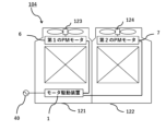
- FIG. 1 is a schematic diagram showing a configuration of a motor drive device according to a first embodiment;
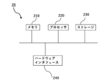
- 2 is a block diagram showing a hardware configuration of a control device included in the motor drive device according to the first embodiment.
- FIG. 2 is a block diagram showing the functional configuration of a control device included in the motor drive device according to the first embodiment;
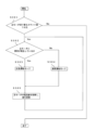
- FIG. 5 is a flowchart showing a main motor switching determination process performed by a control device included in the motor drive device according to the first embodiment.
- FIG. 11 is a schematic diagram showing a configuration of a motor drive device according to a second embodiment.
- FIG. 11 is a block diagram showing a hardware configuration of a control device included in a motor drive device according to a second embodiment.
- FIG. 11 is a block diagram showing the functional configuration of a control device included in a motor drive device according to a second embodiment.
- 10 is a flowchart showing a main motor switching determination process performed by a control device included in the motor drive device according to the second embodiment.
- 10 is a flowchart showing a mode switching determination process performed by a control device included in the motor drive device according to the second embodiment.
- 13 is a flowchart showing the processing of an emergency operation mode in the mode switching determination processing of a control device included in the motor drive device according to the second embodiment.
- FIG. 11 is a schematic diagram showing a configuration of a motor drive device according to a third embodiment.
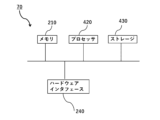
- FIG. 11 is a block diagram showing the hardware configuration of a control device included in a motor drive device according to a third embodiment.
- FIG. 11 is a block diagram showing the functional configuration of a control device included in a motor drive device according to a third embodiment.
- 13 is a flowchart showing the processing of an emergency operation mode in the mode switching determination processing of a control device included in the motor drive device according to embodiment 3.
- Fig. 1 is a refrigerant circuit diagram showing an overview of a refrigeration cycle apparatus 100 according to embodiment 1.
- Fig. 2 is a schematic diagram showing the configuration of an outdoor heat exchanger 104 according to embodiment 1. The configuration of the refrigeration cycle apparatus 100 will be described with reference to Figs. 1 and 2.
- the refrigeration cycle device 100 includes an indoor unit 110 and an outdoor unit 120.
- the flow of refrigerant in the refrigeration cycle device 100 during heating operation is indicated by dashed arrows, and the flow of refrigerant during cooling operation is indicated by solid arrows.
- the indoor unit 110 is fixedly installed indoors.
- the indoor unit 110 is equipped with an indoor heat exchanger 201 that functions as an evaporator during cooling operation and as a condenser during heating operation.
- the indoor heat exchanger 201 is equipped with an indoor fan (not shown) that blows indoor air.
- the outdoor unit 120 is fixedly installed outdoors.
- the outdoor unit 120 is formed by connecting a four-way valve 101 that switches between a refrigerant circuit during heating operation and a refrigerant circuit during cooling operation, a compressor 102 that compresses the refrigerant, a pressure reducing device 103 that reduces the pressure of the refrigerant, and an outdoor heat exchanger 104 that functions as a condenser during cooling operation and as an evaporator during heating operation, through piping 301.
- the pressure reducing device 103 is an expansion valve.
- the outdoor heat exchanger 104 includes a first outdoor heat exchanger 121 and a second outdoor heat exchanger 122.
- the first outdoor heat exchanger 121 and the second outdoor heat exchanger 122 are top-flow type heat exchangers.
- the first outdoor heat exchanger 121 and the second outdoor heat exchanger 122 are each connected in parallel to the refrigerant circuit.
- the first outdoor heat exchanger 121 has a motor drive unit 1, a first PM (Permanent Magnet) motor 6, and a first fan 123.
- the motor drive device 1 receives a voltage output from an AC power source 40 and drives the first PM motor 6 and the second PM motor 7 by outputting a voltage to them.
- the motor drive device 1 also performs vector control on the first PM motor 6 and the second PM motor 7, and determines the voltage command value to be applied to the first PM motor 6 and the second PM motor 7.
- Vector control is a control method in which the current of each phase applied to the motor is separated into a magnetic flux current component (d-axis) and a torque current component (q-axis) and then controlled.
- Vector control methods include, for example, a sensorless vector control method that does not have a feedback signal from a sensor, or a vector control method with encoder feedback that provides feedback from an encoder.
- the control method in embodiment 1 is a vector control method with encoder feedback.
- Vector control with encoder feedback can control the current flow direction while taking into account not only the voltage magnitude and frequency, but also the direction of the current, meaning that there is no torque disturbance even when the load or rotation speed changes suddenly.
- the first PM motor 6 drives the first fan 123.
- a PM motor is a motor with a permanent magnet embedded in the rotor, such as an SPM motor or an IPM motor.
- the first fan 123 blows outdoor air.
- the second outdoor heat exchanger 122 has a second PM motor 7 and a second fan 124.
- the second PM motor 7 drives the second fan 124.
- the second fan 124 blows outdoor air.
- FIG. 3 is a schematic diagram showing the configuration of the motor drive device 1 according to the first embodiment. The configuration of the motor drive device 1 will be explained using FIG. 3.
- the motor drive device 1 has a voltage conversion unit 3, a first rotation detection unit 4, a second rotation detection unit 5, a first disconnecting contactor 8, a second disconnecting contactor 9, a first current detection unit 10, a second current detection unit 11, and a control device 20.
- the voltage conversion unit 3 converts the AC voltage output from the AC power source based on a voltage command value determined by the control device 20, and applies the converted AC voltage to the first PM motor 6 and the second PM motor 7.
- the voltage conversion unit has a converter 30 and an inverter 31.
- the converter 30 is connected to the AC power supply 40 and the inverter 31.
- the converter 30 converts the AC voltage supplied from the AC power supply 40 into a DC voltage.
- the inverter 31 is connected to the converter 30, the first PM motor 6, and the second PM motor 7 by power lines.
- the inverter 31 is also connected in parallel to the first PM motor and the second PM motor, respectively.
- the inverter 31 converts the DC voltage supplied from the converter into a three-phase AC voltage based on a voltage command value, and outputs it to the first PM motor 6 and the second PM motor 7. More specifically, the inverter 31 is connected to the first PM motor by the first U-phase power line 12, the first V-phase power line 13, and the first W-phase power line 14.
- the inverter 31 is also connected to the second PM motor 7 by a second U-phase power line 15 branching off from the first U-phase power line 12, a second V-phase power line 16 branching off from the first V-phase power line 13, and a second W-phase power line 17 branching off from the first W-phase power line 14.
- the first rotation detector 4 detects the first rotation speed, which is the rotation speed of the first PM motor.
- the first rotation detector 4 also transmits a signal including the detected first rotation speed to the control device 20.
- the first rotation detector 4 is, for example, a rotation angle sensor.
- the second rotation detector 5 detects the second rotation speed, which is the rotation speed of the second PM motor.
- the second rotation detector 5 also transmits a signal including the detected second rotation speed to the control device 20.
- the second rotation detector is, for example, a rotation angle sensor.
- the first disconnecting contactor 8 is inserted in series into two of the three first power lines between the inverter 31 and the first PM motor 6. In the first embodiment, the first disconnecting contactor 8 is inserted into the first U-phase power line 12 and the first W-phase power line. The first disconnecting contactor 8 controls the supply of current to the first PM motor by switching between connection and disconnection of the power lines according to commands from the control device 20.
- the second disconnecting contactor 9 is inserted in series into two of the three second power lines between the inverter 31 and the second PM motor 7.
- the second disconnecting contactor 9 is inserted into the second U-phase power line 15 and the second W-phase power line 17.
- the second disconnecting contactor 9 controls the supply of current to the second PM motor by switching between connection and disconnection of the power lines in accordance with commands from the control device 20.
- the outdoor heat exchanger can operate according to the air conditioning capacity.
- the air conditioning capacity of the refrigeration cycle device 100 is small, it is possible to drive only one motor by connecting a power line to only one of the first PM motor 6 or the second PM motor 7 and disconnecting the power line to the other motor.
- the air conditioning capacity of the refrigeration cycle device 100 is large, it is possible to drive both motors by connecting a power line to both the first PM motor 6 and the second PM motor 7.
- the first current detection unit 10 is inserted in series into two of the three first power lines between the inverter 31 and the first PM motor 6.
- the first current detection unit 10 is inserted into the first U-phase power line 12 and the first W-phase power line 14. That is, the first current detection unit 10 detects the instantaneous value I1u of the current in the first U-phase power line and the instantaneous value I1w of the current in the first W-phase power line.
- the first current detection unit 10 also transmits a signal including the detected instantaneous value I1u of the current in the first U-phase power line and the instantaneous value I1w of the current in the first W-phase power line to the control device 20.
- the first current detection unit 10 is, for example, a current sensor.
- the second current detection unit 11 is inserted in series into two of the three first power lines between the inverter 31 and the second PM motor 7.
- the second current detection unit 11 is inserted into the second U-phase power line 15 and the second W-phase power line 17. That is, the second current detection unit 11 detects the instantaneous value I2u of the current in the second U-phase power line and the instantaneous value I2w of the current in the second W-phase power line 17.
- the second current detection unit 11 also transmits a signal including the detected instantaneous value I2u of the current in the second U-phase power line and the instantaneous value I2w of the current in the second W-phase power line to the control device 20.
- the second current detection unit 11 is, for example, a current sensor.
- the first current detection unit 10 and the second current detection unit 11 acquire the instantaneous value of the current at predetermined intervals.
- FIG. 4 is a block diagram showing the hardware configuration of the control device 20 included in the motor drive device 1 according to the first embodiment.
- FIG. 5 is a block diagram showing the functional configuration of the control device 20 included in the motor drive device 1 according to the first embodiment. The configuration of the control device 20 will be explained using FIG. 4 and FIG. 5.
- control device 20 includes a memory 210, a processor 220, storage 230, and a hardware interface 240.
- Memory 210 stores programs executed by processor 220. Memory 210 is also used as a working area for processor 220. Memory 210 may be, for example, a volatile memory such as RAM (Random Access Memory), a non-volatile memory such as ROM (Read Only Memory), or both volatile and non-volatile memory.
- RAM Random Access Memory
- ROM Read Only Memory
- the processor 220 executes the programs stored in the memory 210. Specifically, the processor 220 executes a program for determining a voltage command value, a program for specifying a first current value, which is the current flowing through the first PM motor, and a second current value, which is the current flowing through the second PM motor, and a program for determining whether to switch the main motor.
- the main motor is either the first PM motor 6 or the second PM motor 7, and the motor drive device 1 determines the voltage command value by performing vector control on the rotation speed, which is a parameter of the main motor.
- the processor 220 is, for example, a CPU (Central Processing Unit).
- the main motor parameters include, for example, the main motor rotation speed, the d-axis inductance value of the main motor, the q-axis inductance value of the main motor, the current value of the main motor, and the motor winding resistance value of the main motor.
- the parameters are not limited to one type of information, and may be a combination of multiple types of information.
- the parameter is the main motor rotation speed.
- the motor drive device 1 performs vector control with encoder feedback. Specifically, the motor drive device 1 performs vector control by comparing the target rotation speed of the main motor obtained from the first PM motor 6 or the second PM motor 7 with the detected rotation speed of the main motor detected by the first rotation detector 4 or the second rotation detector 5.
- Storage 230 stores a threshold value of a current difference value, which is the absolute value of the difference between the first current value and the second current value.
- the first current value is the value of a current flowing through the first PM motor 6.
- the second current value is the value of a current flowing through the second PM motor 7.
- Storage 230 is, for example, a non-volatile memory such as an SSD (Solid State Drive) or a ROM (Read Only Memory) or a hard disk.
- SSD Solid State Drive
- ROM Read Only Memory
- the hardware interface 240 transmits and receives signals wirelessly or wired to and from the hardware interfaces of the voltage conversion unit 3, the first PM motor 6, the second PM motor 7, the first disconnecting contactor 8, the second disconnecting contactor 9, the first current detection unit 10, the second current detection unit 11, the first rotation detection unit 4, and the second rotation detection unit 5.
- control device 20 also includes a voltage command value determination unit 21, a memory unit 22, a current value specification unit 23, a main motor switching unit 24, and a data transmission/reception unit 25.
- the voltage command value determination unit 21 determines a voltage command value for the voltage conversion unit 3 using vector control of the main motor parameters. More specifically, the voltage command value determination unit 21 uses either the first PM motor 6 or the second PM motor 7 as the main motor, compares the target rotation speed of the main motor with the detected rotation speed of the main motor, and performs vector control to determine a voltage command value. The voltage command value determination unit 21 transmits the determined voltage command value to the data transmission/reception unit 25.
- the voltage command value determination unit 21 receives a main motor switching command from the main motor switching unit 24, it acquires the parameters of the main motor after switching.
- the voltage command value determination unit 21 is realized by the memory 210 and the processor 220.
- the memory unit 22 stores a threshold value for the current difference value.
- the memory unit 22 is realized by storing information in the storage 230.
- the current value determination unit 23 determines a first current value, which is the current flowing through the first PM motor 6, and a second current value, which is the current flowing through the second PM motor 7.
- the main motor switching unit 24 judges whether switching between the main motor and the sub-motor is necessary based on the first current value and the second current value identified by the current value identification unit 23, and performs the switching. Specifically, the main motor switching unit 24 judges that switching of the main motor is necessary when the current difference value, which is the absolute value of the difference between the first current value and the second current value, is greater than a predetermined threshold value stored in the memory unit 22, and the current flowing through the sub-motor is greater than the current flowing through the main motor. In other words, if the first PM motor 6 is the main motor, the second PM motor 7 is changed to the main motor. Also, if the second PM motor 7 is the main motor, the first PM motor 6 is changed to the main motor.
- the main motor switching unit 24 transmits a main motor switching command to the voltage command value determination unit 21.
- the main motor switching unit 24 is realized by the memory 210 and the processor 220.
- the data transmission/reception unit 25 transmits signals from the control device 20 or receives signals to the control device 20. More specifically, the data transmission/reception unit 25 receives a signal including an instantaneous value I1u of the current in the first U-phase power line and an instantaneous value I1w of the current in the first W-phase power line from the first current detection unit 10, a signal including an instantaneous value I2U of the current in the second U-phase power line and an instantaneous value I2w of the current in the second W-phase power line from the second current detection unit 11, a signal including a target rotation speed of the main motor from the first PM motor 6 or the second PM motor 7, and a signal including a detected rotation speed of the main motor from the first rotation detection unit 4 or the second rotation detection unit 5.
- the data transmission/reception unit 25 also transmits to the voltage conversion unit 3 a signal including a voltage command value determined by the voltage command value determination unit 21, to the first disconnection contactor 8 a signal including a connect or disconnect command, to the second disconnection contactor 9 a signal including a connect or disconnect command, and to the first PM motor 6, the second PM motor 7, and the inverter 31 a signal including a drive or stop command.
- the data transmission/reception unit 25 is also configured to be able to transmit and receive data to and from each component of the control device 20.
- the data transmission/reception unit 25 is realized by the hardware interface 240.
- the first PM motor 6 and the second PM motor 7 are motors for driving the first fan 123 and the second fan 124 of the outdoor heat exchanger 104, respectively, and are therefore fixedly installed outdoors. Therefore, there may be a difference in the load on the first PM motor 6 and the second PM motor 7 depending on the installation environment of each motor or the characteristics of the motor itself. Installation environments that result in a large load include, for example, when there is a heating element near the motor installation location, or when gusts of wind blow where the motor is installed.
- the load on the auxiliary motor may be greater than the load on the main motor. In such cases, the rotation speed of the auxiliary motor may not reach the target rotation speed. If the rotation speed of the auxiliary motor deviates from the control range, there is a problem that the control may lose synchronization.
- the main motor and the sub motor are switched when the current difference value is greater than a predetermined threshold value and the current flowing through the sub motor is greater than the current flowing through the main motor.
- FIG. 6 is a flowchart showing the main motor switching determination process performed by the control device 20 included in the motor drive device 1 according to the first embodiment. The process performed by the control device will be described with reference to FIG. 6.
- the control device 20 determines that the number of detected rotations of the main motor acquired by the voltage command value determination unit 21 has reached the target number of rotations, it starts the main motor switching determination process.
- Step S101 starts processing when it is determined that the number of detected rotations of the main motor acquired by the voltage command value determination unit 21 has reached the target rotation speed of the main motor.
- the current value determination unit 23 of the control device 20 determines the first current value flowing through the first PM motor 6 and the second current value flowing through the second PM motor 7 from the instantaneous values of the currents detected by the first current detection unit 10 and the second current detection unit 11, respectively.
- the processing of step S101 ends when the current value determination unit 23 determines the first current value and the second current value.
- Step S102 is performed after step S101.
- the main motor switching unit 24 of the control device 20 calculates a current difference value.
- the current difference value is the absolute value of the difference between the first current value and the second current value identified in step S101. Step S102 ends when the main motor switching unit 24 calculates the current difference value.
- Step S103 is performed after step S102.
- the main motor switching unit 24 of the control device 20 determines whether the current difference value calculated in step S102 is greater than a threshold value pre-stored in the memory unit 22.
- the main motor switching unit 24 ends the process when it determines whether the condition is satisfied.
- step S103 If it is determined in step S103 that the current difference value is not greater than the threshold value (step S103, No), the current value determination unit 23 performs step S101.
- Step S104 is performed when it is determined in step S103 that the current difference value is greater than the threshold value (Yes in step S103).
- the main motor switching unit 24 of the control device 20 determines whether the current value flowing through the sub-motor determined in step S101 is greater than the current value flowing through the main motor.
- the main motor switching unit 24 determines whether the second current value is greater than the first current value.
- the main motor switching unit 24 determines whether the first current value is greater than the second current value.
- the processing ends when the main motor switching unit 24 determines whether the condition is satisfied.
- step S104 If it is determined in step S104 that the current value flowing through the sub motor is not greater than the current value flowing through the main motor (step S104, No), the current value determination unit 23 performs step S101.
- Step S105 is performed when it is determined in step S104 that the current value flowing through the auxiliary motor is greater than the current value flowing through the main motor (step S104, Yes).
- the main motor switching unit 24 of the control device 20 switches the main motor. That is, if the first PM motor 6 was the main motor, the second PM motor 7 is the main motor. Also, if the second PM motor 7 was the main motor, the first PM motor 6 is the main motor.
- the main motor switching unit 24 sends a signal including a main motor switching command to the voltage command value determination unit 21. The process of step S105 ends when the main motor switching unit 24 switches the main motor.
- Step S106 is performed after step S105.
- the voltage command value determination unit 21 of the control device 20 changes the voltage command value. Specifically, the voltage command value determination unit 21 determines the voltage command value by performing vector control on the main motor rotation speed, which is the main motor parameter changed in step S105. In step S106, the voltage command value determination unit 21 determines that the number of detected rotations of the main motor has reached the target rotation speed of the main motor, and the voltage command value is determined, and the process ends.
- step S106 the current value determination unit 23 performs step S101.
- the motor drive device 1 includes a voltage conversion unit 3 that applies the converted AC voltage, which is obtained by converting the AC voltage output from the AC power supply 40 based on a voltage command value, to the first motor (corresponding to the first PM motor 6) and the second motor (corresponding to the second PM motor 7), and a control unit (corresponding to the control device 20) that determines a voltage command value from parameters in the first motor when the first current value flowing through the first motor is greater than the second current value flowing through the second motor and a current difference value, which is the absolute value of the difference between the first current value and the second current value, is greater than a predetermined threshold value, and determines a voltage command value from parameters in the second motor when the second current value is greater than the first current value and the current difference value is greater than the threshold value.
- the motor drive device 1 according to the first embodiment has the effect of suppressing step-out.
- the motor driving method includes a first step of acquiring a first current value applied to the first motor (corresponding to the first PM motor 6) and a second current value applied to the second motor (corresponding to the second PM motor 7), a second step of calculating a current difference value, which is the absolute value of the difference between the first current value and the second current value acquired in the first step, a third step of selecting the second motor as the main motor when the second current value is greater than the first current value and the current difference value is greater than a predetermined threshold value, and selecting the first motor as the main motor when the first current value is greater than the second current value and the current difference value is greater than a threshold value, and a fourth step of applying to the first motor and the second motor the converted AC voltage, which is converted based on a voltage command value, which is a value determined from the parameters of the main motor determined in the third step, to the first motor and the second motor.
- the motor driving method has the effect of suppressing step-out.
- the refrigeration cycle device 100 includes a compressor 102, a first outdoor heat exchanger 121 having a first motor (corresponding to the first PM motor 6), an outdoor heat exchanger 104 having a second motor (corresponding to the second PM motor 7) and a second outdoor heat exchanger 122 connected in parallel to the first outdoor heat exchanger 121 with respect to the refrigerant circuit, a pressure reducing device 103, an indoor heat exchanger 201, refrigerant piping (corresponding to piping 301) connecting the compressor 102, the outdoor heat exchanger 104, the pressure reducing device 103, and the indoor heat exchanger 201 so that the refrigerant circulates between each of the devices, and a power supply 40 connected to the outdoor heat exchanger 121.
- the motor drive device 1 includes a voltage conversion unit 3 that converts an AC voltage based on a voltage command value and applies the converted AC voltage to the first motor and the second motor, and a control unit (corresponding to the control device 20) that determines a voltage command value from parameters in the second motor when the second current value flowing through the second motor is greater than the first current value flowing through the first motor and a current difference value, which is the absolute value of the difference between the first current value and the second current value, is greater than a predetermined threshold value, and determines a voltage command value from parameters in the first motor when the first current value is greater than the second current value and the current difference value is greater than a threshold value.
- the refrigeration cycle device 100 according to the first embodiment has the effect of suppressing loss of synchronism.
- the motor drive device 1 according to the first embodiment has an additional configuration in which the first current value is the instantaneous value of the current flowing through the first motor (corresponding to the first PM motor 6), and the second current value is the instantaneous value of the current flowing through the second motor (corresponding to the second PM motor 7).
- the motor drive device 1 according to the first embodiment has the effect of being able to quickly perform motor drive control.
- the motor drive device 1 according to the first embodiment has an additional configuration in which the parameters include the motor rotation speed.
- This additional configuration provides the motor drive device 1 according to the first embodiment with the effect of being able to perform appropriate control according to the driving conditions of the motor.
- the motor drive device 1 has a first motor (corresponding to the first PM motor 6) and a second motor (corresponding to the second PM motor 7) that are three-phase AC motors
- the voltage conversion unit 3 has a converter 30 that converts the AC voltage output from the AC power source 40 into a DC voltage, and an inverter 31 that applies a three-phase AC voltage converted from the DC voltage converted by the converter 30 based on a voltage command value to the first motor and the second motor.
- the motor drive device 1 according to the first embodiment has an additional configuration in which the first current value is determined by detecting the current values of two or more phases of the first motor (corresponding to the first PM motor 6), and the second current value is determined by detecting the current values of two or more phases of the second motor (corresponding to the second PM motor 7).
- the motor drive device 1 according to the first embodiment has the effect of being able to detect the current values of all three phases in a three-phase AC motor.
- the motor drive device 1 has a control unit (corresponding to the control device 20) that determines a voltage command value by performing vector control from parameters of either the first motor (corresponding to the first PM motor 6) or the second motor (corresponding to the second PM motor 7).
- This additional configuration enables the motor drive device 1 according to the first embodiment to achieve the effect of being able to perform control taking into account not only the magnitude and frequency of the voltage, but also the direction of the current flow.
- the motor drive method according to the first embodiment has the following configuration: the first current value acquired in the first step is the instantaneous value of the current flowing through the first motor (corresponding to the first PM motor 6), and the second current value is the instantaneous value of the current flowing through the second motor (corresponding to the second PM motor 7).
- the motor drive method according to the first embodiment has the effect of being able to quickly perform motor drive control.
- the motor driving method according to the first embodiment has the first motor (corresponding to the first PM motor 6) and the second motor (corresponding to the second PM motor 7) being three-phase AC motors
- the voltage conversion unit 3 has a converter 30 that converts the AC voltage output from the AC power source 40 into a DC voltage, and an inverter 31 that applies to the first motor and the second motor a three-phase AC voltage converted from the DC voltage converted by the converter 30 based on a voltage command value.
- the motor driving method according to the first embodiment has a first current value obtained in the first step that is determined by detecting the current values of two or more phases of the first motor (corresponding to the first PM motor 6), and the second current value that is determined by detecting the current values of two or more phases of the second motor (corresponding to the second PM motor 7).
- the motor driving method according to the first embodiment has the effect of being able to detect the current values of all three phases in a three-phase AC motor.
- the motor driving method according to the first embodiment has a control unit (corresponding to the control device 20) that determines a voltage command value by performing vector control from parameters of either the first motor (corresponding to the first PM motor 6) or the second motor (corresponding to the second PM motor 7) in the fourth step.
- the motor driving method according to the first embodiment has the effect of being able to perform control taking into account not only the magnitude and frequency of the voltage, but also the direction of the current flow.
- the refrigeration cycle device 100 according to the first embodiment has, as an additional configuration, the first current value being the instantaneous value of the current flowing through the first motor (corresponding to the first PM motor 6), and the second current value being the instantaneous value of the current flowing through the second motor (corresponding to the second PM motor 7).
- the refrigeration cycle device 100 according to the first embodiment has the effect of being able to quickly perform motor drive control.
- the parameters of the refrigeration cycle device 100 according to the first embodiment include the rotation speed of the motor.
- the refrigeration cycle device 100 according to the first embodiment has the effect of being able to perform appropriate control according to the driving status of the motor.
- the refrigeration cycle device 100 has a first motor (corresponding to the first PM motor 6) and a second motor (corresponding to the second PM motor 7) that are three-phase AC motors
- the voltage conversion unit 3 has a converter 30 that converts the AC voltage output from the AC power source 40 into a DC voltage, and an inverter 31 that applies a three-phase AC voltage converted from the DC voltage converted by the converter 30 based on a voltage command value to the first motor and the second motor.
- the refrigeration cycle device 100 according to embodiment 1 has a first current value determined by detecting the current values of two or more phases of the first motor (corresponding to the first PM motor 6), and a second current value determined by detecting the current values of two or more phases of the second motor (corresponding to the second PM motor 7).
- the refrigeration cycle device 100 according to embodiment 1 has the effect of being able to detect the current values of all three phases in a three-phase AC motor.
- the motor drive device 1 has a control unit (corresponding to the control device 20) that determines a voltage command value by performing vector control from parameters of either the first motor (corresponding to the first PM motor 6) or the second motor (corresponding to the second PM motor 7).
- This additional configuration provides the effect that the refrigeration cycle device 100 according to the first embodiment can perform control taking into account not only the magnitude and frequency of the voltage, but also the direction of the current flow.
- the outdoor heat exchanger is a top-flow type, but this is not limited to this.
- it may be a side-flow type.
- the motor drive unit is built into the first outdoor heat exchanger, but this is not limited to the configuration.
- the motor drive unit may be built into the second outdoor heat exchanger, or may be provided as a separate device outside the outdoor heat exchanger.
- the motor drive device is configured to drive the motor of the outdoor heat exchanger, but this is not limited to this.
- the motor drive device may be configured to drive the motor of the indoor heat exchanger.
- the motor drive device may be configured to drive a motor other than that of the refrigeration cycle device.
- the first PM motor is provided in the first outdoor heat exchanger
- the second PM motor is provided in the second outdoor heat exchanger, but this is not limited to the configuration.
- the first PM motor and the second PM motor may both be provided in one outdoor heat exchanger.
- the current detection unit and the disconnecting contactor are inserted into two of the three power lines connected to the motor, but this is not limited to the configuration.
- the current detection unit and the disconnecting contactor may be inserted into all three power lines.
- a disconnecting contactor is inserted into the power lines connected to the first PM motor and the second PM motor, but this is not limited to the configuration.
- a disconnecting contactor may be inserted only into the power lines connected to the first PM motor, or a disconnecting contactor may be inserted only into the power lines connected to the second PM motor. Even in such a configuration, by disconnecting the power lines connected to one of the motors, it is possible to drive only the other motor. Also, a configuration without a disconnecting contactor may be used.
- the motor drive device is configured to perform vector control on the parameters of the main motor to determine the voltage command value, but this is not limited to the configuration.
- the motor drive device may perform V/f control, or may be configured to determine the voltage command value by performing control based on position detection by a Hall sensor.
- the inverter outputs a three-phase AC voltage, but this is not limited to the configuration.
- the inverter may output a single-phase AC voltage.
- the motor drive device is configured to control two motors, but this is not limited to the above.
- the motor drive device may be configured to control two or more motors.
- the configuration has multiple auxiliary motors.
- the motor controlled by the motor drive device is a PM motor, but this is not limited to this.
- the motor controlled by the motor drive device may be an induction motor.
- the main motor switching unit is configured to switch the main motor while keeping the motor and the inverter driven, but this is not limited to the above.
- the configuration may be such that the drive of the motor is temporarily stopped when switching the main motor. By configuring the drive of the motor to be temporarily stopped when switching the main motor, it is possible to prevent a momentary increase in current.
- the current difference value is calculated from the instantaneous value of the current flowing through the first PM motor and the instantaneous value of the current flowing through the second PM motor, but this is not limited to the above.
- the current difference value may be calculated from the value of the torque current component (q-axis) of the current flowing through the first PM motor and the second PM motor. By calculating the current difference value from the value of the torque current component, it is possible to perform torque control quickly.
- the average value of the magnitude of the current over a predetermined time may be used instead of the instantaneous value of the current.
- the current value flowing through the auxiliary motor is compared with the current value flowing through the main motor, but this is not limited to this. It may be configured such that after the current value flowing through the auxiliary motor is compared with the current value flowing through the main motor, the current difference value is compared with the threshold value.
- Embodiment 2 A motor drive device 2 according to embodiment 2 will be described.
- the motor drive device 2 according to embodiment 2 is different in configuration from that of embodiment 1.
- the outline of a refrigeration cycle apparatus 100 including a motor drive device 2 according to embodiment 2 and the configuration of an outdoor heat exchanger 104 are similar to those of embodiment 1, and therefore description thereof will be omitted.
- FIG. 7 is a schematic diagram showing the configuration of a motor drive device 2 according to the second embodiment. The configuration of the motor drive device 2 will be explained using FIG. 7.
- the configuration of motor drive device 2 differs from motor drive device 1 in that the first PM motor 6 and the second PM motor 7 are operated in one of two operating modes, and in that it is equipped with a display unit 26.
- the operating modes of the first PM motor 6 and the second PM motor 7, and the configuration excluding the display unit 26 are the same as those of motor drive device 1, so a description thereof will be omitted.
- the first PM motor 6 and the second PM motor 7 are operated in either a normal operation mode or an emergency operation mode.
- the first PM motor 6 and the second PM motor 7 are operated in the normal operation mode when driving and when it is determined that no abnormality has occurred in the main motor.
- the first PM motor 6 and the second PM motor 7 are operated at the designed rated frequency by vector control of the set main motor parameters.
- the first PM motor 6 and the second PM motor 7 operate in an emergency operation mode.
- the first PM motor and the second PM motor 7 operate in a stable frequency band that is a frequency lower than the designed rated frequency.
- the value of the main motor parameter that determines the voltage command value of the voltage flowing to the first PM motor 6 and the second PM motor 7 is changed.
- the main motor parameters in embodiment 2 are the main motor rotation speed, the main motor d-axis inductance value, and the main motor q-axis inductance value.
- the main motor parameter values are changed based on the current value flowing through the main motor. More specifically, in emergency operation mode, the target rotation speed of the main motor is set lower than the values set in normal operation mode, and the d-axis inductance value and q-axis inductance of the main motor are set to smaller values.
- the display unit 26 displays mode information.
- Mode information is information received from the control device 50 and indicates the operating status of the motor. Specifically, the display unit 26 displays that the inverter 41 is operating in the normal operating mode or the emergency operating mode.
- the motor drive device 2 has a display unit 26, which has the effect of being able to inform the operator of the operating status of the motor.
- FIG. 8 is a block diagram showing the hardware configuration of the control device 50 included in the motor drive device 2 according to the second embodiment.
- FIG. 9 is a block diagram showing the functional configuration of the control device 50 included in the motor drive device 2 according to the second embodiment. The configuration of the control device 50 will be explained using FIG. 8 and FIG. 9.
- the hardware configuration of the control device 50 differs in the programs executed by the processor 320 and the information stored in the storage 330.
- the configuration other than the programs executed by the processor 320 and the information stored in the storage 330 is the same as that of the control device 20, and therefore a description thereof will be omitted.
- the processor 320 executes a program for determining a voltage command value, a program for specifying a first current value, which is the current flowing through the first PM motor 6, and a second current value, which is the current flowing through the second PM motor 7, a program for determining whether to switch the main motor, and a program for determining whether to switch the operating modes of the first PM motor 6 and the second PM motor 7.
- Storage 330 stores a threshold value for the current difference value, an allowable current value, and a main motor switching count value.
- the allowable current value is a current value associated with a voltage command value, and indicates the upper limit of the current value when no abnormality occurs in the motor.
- the allowable current value is also determined to an arbitrary value by the designer of motor drive device 1 based on the results of experiments or simulations.
- the main motor switching count value is a value indicating the number of times the switching process between the main motor and the auxiliary motor has been performed, and is 0 when the motor is being driven.
- the functional configuration of the control device 50 differs from that of the first embodiment in the contents stored in the memory unit 32, the inclusion of a mode switching unit 34, and the signals transmitted by the data transmission/reception unit 35.
- the contents stored in the memory unit 32, and the configuration excluding the mode switching unit 34 and the data transmission/reception unit 35 are the same as those of the control device 20, and therefore a description thereof will be omitted.
- the memory unit 32 stores the threshold value of the current difference value, the allowable current value, and the main motor switching count value.
- the mode switching unit 34 determines whether to switch the operation mode of the first PM motor 6 and the second PM motor 7 by determining whether the current value of the main motor is equal to or less than the allowable current value corresponding to the voltage command value. More specifically, when the current value of the main motor is equal to or less than the allowable current value corresponding to the voltage command value, the mode switching unit 34 operates the first PM motor 6 and the second PM motor 7 in the normal operation mode. Furthermore, when the current value of the main motor is greater than the allowable current value corresponding to the voltage command value, the mode switching unit 34 operates the first PM motor 6 and the second PM motor 7 in the emergency operation mode.
- the data transmission/reception unit 35 differs in that it transmits a signal including mode information to the display unit 26.
- the motor drive device can control the motor under load as the main motor. This process can prevent loss of control.
- the motor drive device 2 in addition to switching the main motor, if it is determined that an abnormality has occurred in the motor, the motor drive device 2 also switches the motor's operation mode to an emergency operation mode, making it possible to perform operation that takes the abnormality into consideration even when an abnormality has occurred in the motor.
- FIG. 10 is a flowchart showing the main motor switching determination process performed by the control device 50 included in the motor drive device 2 according to the second embodiment.
- FIG. 11 is a flowchart showing the mode switching determination process performed by the control device 50 included in the motor drive device 2 according to the second embodiment.
- FIG. 12 is a flowchart showing the emergency operation mode process in the mode switching determination process of the control device 50 included in the motor drive device 2 according to the second embodiment.
- FIG. 12 is a flowchart for explaining step S304 in FIG. 11 in more detail. The process performed by the control device 50 will be explained using FIG. 10 to FIG. 12.
- the main motor switching determination process in the second embodiment differs from the main motor switching determination process in the first embodiment in that the process ends when the main motor switching unit 24 of the control device 50 determines that switching of the main motor is not necessary, and that the storage unit 32 stores a main motor switching count value. Also, unlike the first embodiment, the control device 50 in the second embodiment starts a mode switching determination process when the main motor switching determination process ends.
- control device 50 determines that the number of detected rotations of the main motor acquired by the voltage command value determination unit 21 has reached the target rotation speed, it starts the main motor switching determination process shown in FIG. 10.
- Step S201 starts processing when it is determined that the number of detected rotations of the main motor acquired by the voltage command value determination unit 21 has reached the target rotation speed of the main motor.
- the data transmission/reception unit 35 transmits a signal to the display unit 26 including a signal indicating that the first PM motor 6 and the second PM motor 7 are operating in the normal operation mode.
- the processing in step S201 ends when the data transmission/reception unit 35 transmits a signal to the display unit 26 indicating that they are operating in the normal operation mode.
- Step S202 is performed after step S201. Steps S202 to S206 are similar to steps S101 to S105 in the first embodiment, and therefore will not be described. Step S205 ends when the main motor switching unit 24 determines whether the conditions are met.
- Step S207 is performed after step S206.
- the memory unit 32 adds 1 to the stored main motor switching count value to update the value.
- the memory unit 32 updates the main motor switching count value, and the process ends.
- Step S208 is performed after step S207.
- the process of step S208 is similar to the process of step S106 in the first embodiment, and therefore will not be described.
- the voltage command value determination unit 21 determines that the number of detected rotations of the main motor has reached the target rotation speed of the main motor and determines the voltage command value, at which point the process ends.
- the main motor switching determination process performed by the control device 50 ends when it is determined in step S204 that the current difference value is not greater than the threshold value (step S204, No), or when it is determined in step S205 that the current value flowing through the sub motor is not greater than the current value flowing through the main motor (step S205, No).
- control device 50 finishes the main motor switching determination process, it starts the mode switching determination process shown in FIG. 11.
- Step S301 is performed when the main motor switching determination process is completed.
- the mode switching unit 34 of the control device 50 determines whether the main motor switching count value stored in the memory unit 32 is 1 or greater.
- the process ends when the mode switching unit 34 determines whether the condition is satisfied.
- Step S302 is performed after step S301.
- the mode switching unit 34 of the control device 50 determines whether an abnormality has occurred in the main motor. More specifically, the mode switching unit 34 determines whether the current value of the main motor identified in step S201 is equal to or less than the allowable current value corresponding to the voltage command value stored in the memory unit 32. The process of step S302 ends when the mode switching unit 34 determines whether the condition is satisfied.
- Step S303 is performed when it is determined in step S302 that an abnormality has occurred in the main motor (Yes in step S302).
- the mode switching unit 34 of the control device 50 operates the first PM motor 6 and the second PM motor 7 in emergency operation mode. More specifically, the process of step S303 performs the processes of steps S311 to S314 as shown in FIG. 12. The processes of steps S311 to S314 will be described below.
- Step S311 is performed when it is determined in step S302 that an abnormality has occurred in the main motor (step S302, Yes).
- step S311 the mode switching unit 34 of the control device 50 changes the drive frequency of the main motor and the sub motor to a stable frequency band that is a frequency lower than the designed rated frequency.
- the process of step S311 ends when the mode switching unit 34 changes the frequency.
- Step S312 is performed after the processing of step S311.
- the mode switching unit 34 of the control device 50 changes the parameters of the main motor. More specifically, the mode switching unit 34 sets the parameters of the main motor to values that are lower than the target rotation speed of the main motor and smaller than the values set when the motor is driven, and the d-axis inductance value and q-axis inductance value of the main motor.
- the mode switching unit 34 also overwrites and changes the parameters of the main motor stored in the memory unit 32.
- the processing of step S312 ends when the mode switching unit 34 changes the parameters of the main motor.
- Step S313 is performed after step S312.
- the voltage command value determination unit 21 of the control device 50 determines a voltage command value based on the main motor parameters changed in step S312.
- the process of step S313 ends when the voltage command value determination unit 21 determines the voltage command value.
- Step S314 is performed after step S313.
- the data transmission/reception unit 35 of the control device 50 transmits to the display unit 26 a signal including a signal indicating that the first PM motor 6 and the second PM motor 7 are operating in the emergency operation mode.
- the processing of step S314 ends when the data transmission/reception unit 35 transmits to the display unit 26 a signal indicating that they are operating in the emergency operation mode.
- step S314 processing of step S303 is terminated.
- Step S304 is performed when it is determined in step S302 that no abnormality has occurred in the main motor (step S302, No).
- the mode switching unit 34 of the control device 50 operates the first PM motor 6 and the second PM motor 7 in normal operation mode. More specifically, the mode switching unit 34 operates the first PM motor 6 and the second PM motor 7 at the set rated frequency and based on the main motor parameters stored in the memory unit 32.
- the processing ends when the mode switching unit 34 operates the first PM motor 6 and the second PM motor 7 in normal operation mode.
- Step S305 is performed after the processing of step S303 or after the processing of step S304.
- the current value determination unit 23 of the control device 50 determines the value of the current flowing through the main motor from the instantaneous value of the current detected by the first current detection unit 10 or the second current detection unit 11, and updates the value of the current flowing through the main motor.
- the current value determination unit 23 acquires and updates the value of the current flowing through the main motor, and the processing ends.
- step S302 the mode switching unit 34 performs step S302.
- the control device 50 always performs steps S302 to S305 while the motor is operating.
- the mode switching determination process performed by the control device 50 ends when it is determined in step S301 that the main motor switching count value is less than 1, i.e., 0 (step S301, No).
- the load on the main motor is greater than that on the auxiliary motor, or the difference in load between the auxiliary motor and the main motor is small. Therefore, even if the motor drive frequency and main motor parameters are not changed, the control is unlikely to cause step-out.
- the display unit is configured to display the operation mode of the motor, but this is not limited to the above.
- the display unit may be configured to display the main motor, or may be configured to display the parameters of the main motor.
- the display unit may not have a display unit.
- the main motor switching count value when the main motor switching count value is 1 or more, the same processing is performed, but this is not limited to the above.
- the motor may be operated in emergency operation mode. This is because in such a case, the main motor has been switched multiple times, and there is a high possibility that an abnormality has occurred in the motor while it was operating.
- the main motor parameters in the second embodiment are the main motor rotation speed, the d-axis inductance value of the main motor, and the q-axis inductance value of the main motor, but are not limited to this.
- the main motor parameter may be only the d-axis inductance value.
- the motor drive device 2 includes a voltage conversion unit 3 that applies the converted AC voltage, which is obtained by converting the AC voltage output from the AC power source 40 based on a voltage command value, to the first motor (corresponding to the first PM motor 6) and the second motor (corresponding to the second PM motor 7), and a control unit (corresponding to the control device 50) that determines a voltage command value from parameters in the first motor when the first current value flowing through the first motor is greater than the second current value flowing through the second motor and the current difference value, which is the absolute value of the difference between the first current value and the second current value, is greater than a predetermined threshold value, and determines a voltage command value from parameters in the second motor when the second current value is greater than the first current value and the current difference value is greater than the threshold value.
- the motor drive device 2 according to the second embodiment achieves the same effects as those described in the first embodiment.
- the motor driving method includes a first step of acquiring a first current value applied to the first motor (corresponding to the first PM motor 6) and a second current value applied to the second motor (corresponding to the second PM motor 7), a second step of calculating a current difference value, which is the absolute value of the difference between the first current value and the second current value acquired in the first step, a third step of selecting the second motor as the main motor when the second current value is greater than the first current value and the current difference value is greater than a predetermined threshold value, and selecting the first motor as the main motor when the first current value is greater than the second current value and the current difference value is greater than a threshold value, and a fourth step of applying to the first motor and the second motor the converted AC voltage, which is converted based on a voltage command value, which is a value determined from the parameters of the main motor determined in the third step, to the first motor and the second motor.
- the motor driving method achieves the same effects as those described in the first embodiment.
- the refrigeration cycle device includes a compressor 102, a first outdoor heat exchanger 121 having a first motor (corresponding to the first PM motor 6), an outdoor heat exchanger 104 having a second motor (corresponding to the second PM motor 7) and a second outdoor heat exchanger 122 connected in parallel to the first outdoor heat exchanger 121 with respect to the refrigerant circuit, a pressure reducing device 103, an indoor heat exchanger 201, refrigerant piping (corresponding to piping 301) connecting the compressor 102, the outdoor heat exchanger 104, the pressure reducing device 103, and the indoor heat exchanger 201 so that the refrigerant circulates between each of the devices, and an AC power source 40.
- the refrigeration cycle device includes a voltage conversion unit 3 that converts the AC voltage output from the first motor based on a voltage command value and applies the converted AC voltage to the first motor and the second motor, and a control unit (corresponding to the control device 50) that determines a voltage command value from parameters in the second motor when the second current value flowing through the second motor is greater than the first current value flowing through the first motor and a current difference value, which is the absolute value of the difference between the first current value and the second current value, is greater than a predetermined threshold value, and determines a voltage command value from parameters in the first motor when the first current value is greater than the second current value and the current difference value is greater than the threshold value.
- the refrigeration cycle device achieves the same effects as those described in the first embodiment.
- the motor drive device 2 has a control unit (corresponding to the control device 50) that has a main motor switching unit 24 that switches the motor from which parameters are acquired, and the main motor switching unit 24 determines a voltage command value from parameters in the first motor (corresponding to the first PM motor 6), and switches the motor from which parameters are acquired to the second motor when the second current value is greater than the first current value and the current difference value is greater than a threshold value, and switches the motor from which parameters are acquired to the first motor when the voltage command value is determined from parameters in the second motor and the first current value is greater than the second current value and the current difference value is greater than a threshold value, and the control unit changes the parameter to a value that reduces the load on the motor when the main motor switching unit 24 switches the motor from which parameters are acquired and the current flowing through the motor from which parameters are acquired is greater than a predetermined allowable current value corresponding to the voltage command value.
- the motor drive device 2 according to the second embodiment has the effect of being able
- the motor drive device 2 according to the second embodiment further includes a display unit 26 that displays that the first motor (corresponding to the first PM motor 6) and the second motor (corresponding to the second PM motor 7) are being operated in a different operating condition than normal when the parameter is changed to a value that reduces the load on the motor.
- the motor drive device 2 according to the second embodiment has the effect of being able to inform the operator of the operating condition of the motor.
- the motor drive method according to the second embodiment also has, as an additional configuration, a fifth step in which the main motor is switched in the fourth step, and if the current flowing through the main motor is greater than a predetermined allowable current value corresponding to the voltage command value, the parameter is changed to a value that reduces the load on the motor.
- This additional configuration provides the effect that the motor drive device 2 according to the second embodiment can perform operation taking into account an abnormality even when an abnormality occurs in the main motor.
- the motor drive method according to the second embodiment also has, as an additional configuration, a sixth step of displaying on the display unit 26 that, when the parameter is changed to a value that reduces the load on the motor, the first motor (corresponding to the first PM motor 6) and the second motor (corresponding to the second PM motor 7) are being operated in a different operating condition than normal.
- the motor drive method according to the second embodiment has the effect of being able to inform the operator of the operating condition of the motor.
- the refrigeration cycle device has, as an additional configuration, a control unit (corresponding to the control device 50) having a main motor switching unit 24 that switches the motor from which parameters are acquired, and the main motor switching unit 24 determines a voltage command value from parameters in the first motor (corresponding to the first PM motor 6), and switches the motor from which parameters are acquired to the second motor when the second current value is greater than the first current value and the current difference value is greater than the threshold value, and determines a voltage command value from parameters in the second motor, and switches the motor from which parameters are acquired to the first motor when the first current value is greater than the second current value and the current difference value is greater than the threshold value, and the control unit changes the parameter to a value that reduces the load on the motor when the main motor switching unit 24 switches the motor from which parameters are acquired and the current flowing through the motor from which parameters are acquired is greater than a predetermined allowable current value corresponding to the voltage command value.
- the refrigeration cycle device has the effect of being able to operate
- the refrigeration cycle device further includes, as an additional configuration, a display unit 26 that displays that the first motor (corresponding to the first PM motor 6) and the second motor (corresponding to the second PM motor 7) are operating in a different operating condition than normal when the parameter is changed to a value that reduces the load on the motor.
- This additional configuration allows the refrigeration cycle device according to the second embodiment to have the effect of informing the operator of the operating condition of the motor.
- Embodiment 3 A description will be given of a motor drive device 60 according to embodiment 3.
- the motor drive device 60 according to embodiment 3 is different in configuration from the motor drive device 60 according to embodiments 1 and 2.
- the outline of a refrigeration cycle apparatus 100 including a motor drive device 2 according to embodiment 3 and the configuration of an outdoor heat exchanger 104 are similar to those of embodiments 1 and 2, and therefore description thereof will be omitted.
- FIG. 13 is a schematic diagram showing the configuration of a motor drive device 60 according to embodiment 3. The configuration of the motor drive device 60 will be described using FIG. 13.
- motor drive device 60 differs from motor drive device 2 in that it has a first temperature detection unit 61 and a second temperature detection unit 62, and in the content displayed by display unit 36.
- the configuration excluding first temperature detection unit 61 and second temperature detection unit 62 is the same as that of motor drive device 2, so a description thereof will be omitted.
- the first temperature detection unit 61 is provided around the first PM motor 6 and obtains a first temperature value, which is the temperature around the first PM motor 6, at predetermined time intervals.
- the second temperature detection unit 62 is provided around the second PM motor 7 and obtains a second temperature value, which is the temperature around the second PM motor 7, at predetermined time intervals.
- the motor drive device 60 can determine the type of abnormality occurring in the motor. More specifically, if the first temperature value or the second temperature value, which is the ambient temperature of the main motor, is higher than a predetermined allowable temperature value, the motor drive device 60 determines that the main motor is demagnetized. Furthermore, if the ambient temperature of the main motor is equal to or lower than the predetermined allowable temperature value, the motor drive device 60 determines that the motor is broken.
- the allowable temperature value indicates the upper limit of the ambient temperature when no abnormality occurs in the main motor. Furthermore, the allowable temperature value is set to an arbitrary value by the designer of the motor drive device 60 based on the results of experiments or simulations.
- the motor demagnetizes.
- the reason for the abnormality is reversible demagnetization of the motor.
- the reason for the abnormality is irreversible failure of the motor.
- the display unit 36 displays mode information. Furthermore, when it is determined that an abnormality has occurred in the motor and the motor is operating in emergency operation mode, the display unit 36 displays the type of motor abnormality. In other words, the display unit 36 displays whether the motor is demagnetized or broken.
- the motor drive device 60 in the third embodiment displays the type of motor abnormality on the display unit 36.
- the motor drive device 60 has the effect of being able to inform the operator of the detailed status of the motor during operation.
- FIG. 14 is a block diagram showing the hardware configuration of the control device 70 included in the motor drive device 60 according to the third embodiment.
- FIG. 15 is a block diagram showing the functional configuration of the control device 70 included in the motor drive device 60 according to the third embodiment. The configuration of the control device 70 will be explained using FIG. 14 and FIG. 15.
- the hardware configuration of the control device 70 differs from that of the second embodiment in the programs executed by the processor 420 and the information stored in the storage 430.
- the configuration other than the programs executed by the processor 420 and the information stored in the storage 430 is the same as that of the control device 50, and therefore a description thereof will be omitted.
- the processor 420 executes a program for determining a voltage command value, a program for identifying a first current value, which is the current flowing through the first PM motor 6, and a second current value, which is the current flowing through the second PM motor 7, a program for determining whether to switch the main motor, a program for determining whether to switch the operation modes of the first PM motor 6 and the second PM motor 7, and a program for determining the type of abnormality in the main motor when the first PM motor 6 and the second PM motor are operated in an emergency operation mode.
- Storage 430 stores the threshold current difference value, the allowable current value, the main motor switching count value, and the allowable temperature value.
- the functional configuration of the control device 70 differs in the contents stored in the memory unit 72, the signals transmitted and received by the data transmission/reception unit 75, and the processing performed by the mode switching unit 76.
- the configuration other than the contents stored in the memory unit 72, the signals received by the data transmission/reception unit 75, and the processing performed by the mode switching unit 76 is the same as that of the control device 50, and therefore a description thereof will be omitted.
- the memory unit 72 stores a threshold value for the current difference value, a permissible current value, a main motor switching count value, and a permissible temperature value.
- the data transmission/reception unit 75 receives a first temperature value from the first temperature detection unit 61 and a second temperature value from the second temperature detection unit 62. Also, the data transmission/reception unit 75 differs in that it transmits a signal including mode information and a signal including the type of motor abnormality to the display unit 36.
- the mode switching unit 76 determines whether to switch the operating mode of the first PM motor 6 and the second PM motor 7, and determines the type of motor abnormality.
- the type of motor abnormality determined by the mode switching unit 76 is displayed on the display unit 36.
- FIG. 16 is a flowchart showing the processing of the emergency operation mode in the mode switching determination process of the control device 70 included in the motor drive device 60 according to embodiment 3.
- the processing performed by the control device 70 will be described using FIG. 16.
- the main motor switching determination process and the mode switching determination process performed by the control device 70 included in the motor drive device 60 according to embodiment 3 are similar to those of the control device 50, and therefore will not be described.
- Step S411 is performed when it is determined in step S302 that an abnormality has occurred in the main motor (step S302, Yes).
- the processes in steps S411 to S413 are similar to those in steps S311 to S313 in the second embodiment, and therefore will not be described.
- the process in step S413 ends when the voltage command value determination unit 21 determines the voltage command value.
- Step S414 is performed after step S413.
- the mode switching unit 76 of the control device 70 determines whether the ambient temperature of the main motor is equal to or lower than the allowable temperature stored in the memory unit 72.
- the mode switching unit 76 acquires a first temperature if the main motor is the first PM motor 6, and acquires a second temperature if the main motor is the second PM motor 7.
- the mode switching unit 76 determines whether the conditions are met and ends the process.
- Step S415 is performed when it is determined in step S414 that the ambient temperature of the main motor is below the allowable temperature (step S414, Yes).
- step S415 the data transmission/reception unit 75 of the control device 70 transmits a signal to the display unit 36, including a signal indicating that the first PM motor 6 and the second PM motor 7 are operating in emergency operation mode and that a failure has occurred in the main motor.
- the processing of step S415 ends when the data transmission/reception unit 75 transmits a signal to the display unit 36.
- Step S416 is performed when it is determined in step S414 that the first temperature or the second temperature is higher than the allowable temperature (step S414, No).
- step S416 the data transmission/reception unit 75 of the control device 70 transmits a signal to the display unit 36 indicating that the first PM motor 6 and the second PM motor 7 are operating in emergency operation mode and that the main motor has been demagnetized due to high temperature.
- the process of step S416 ends when the data transmission/reception unit 75 transmits a signal to the display unit 36.
- step S415 or step S416 When step S415 or step S416 is completed, the processing of step S303 is terminated.
- the motor drive device 60 includes a voltage conversion unit 3 that applies the converted AC voltage, which is obtained by converting the AC voltage output from the AC power source 40 based on a voltage command value, to the first motor (corresponding to the first PM motor 6) and the second motor (corresponding to the second PM motor 7), and a control unit (corresponding to the control device 70) that determines a voltage command value from parameters in the first motor when the first current value flowing through the first motor is greater than the second current value flowing through the second motor and the current difference value, which is the absolute value of the difference between the first current value and the second current value, is greater than a predetermined threshold value, and determines a voltage command value from parameters in the second motor when the second current value is greater than the first current value and the current difference value is greater than the threshold value.
- the motor drive device 60 according to the third embodiment achieves the same effects as those described in the first embodiment.
- the motor driving method includes a first step of acquiring a first current value applied to the first motor (corresponding to the first PM motor 6) and a second current value applied to the second motor (corresponding to the second PM motor 7), a second step of calculating a current difference value, which is the absolute value of the difference between the first current value and the second current value acquired in the first step, a third step of selecting the second motor as the main motor when the second current value is greater than the first current value and the current difference value is greater than a predetermined threshold value, and selecting the first motor as the main motor when the first current value is greater than the second current value and the current difference value is greater than a threshold value, and a fourth step of applying to the first motor and the second motor the converted AC voltage, which is obtained by converting the AC voltage output from the AC power source 40 based on a voltage command value, which is a value determined from the parameters of the main motor determined in the third step.
- the refrigeration cycle device includes a compressor 102, a first outdoor heat exchanger 121 having a first motor (corresponding to the first PM motor 6), an outdoor heat exchanger 104 having a second motor (corresponding to the second PM motor 7) and a second outdoor heat exchanger 122 connected in parallel to the first outdoor heat exchanger 121 with respect to the refrigerant circuit, a pressure reducing device 103, an indoor heat exchanger 201, refrigerant piping (corresponding to piping 301) connecting the compressor 102, the outdoor heat exchanger 104, the pressure reducing device 103, and the indoor heat exchanger 201 so that the refrigerant circulates between each of the devices, and an AC power source 40.
- the refrigeration cycle device includes a voltage conversion unit 3 that converts the AC voltage output from the first motor based on a voltage command value and applies the converted AC voltage to the first motor and the second motor, and a control unit (corresponding to the control device 70) that determines a voltage command value from parameters in the second motor when the second current value flowing through the second motor is greater than the first current value flowing through the first motor and a current difference value, which is the absolute value of the difference between the first current value and the second current value, is greater than a predetermined threshold value, and determines a voltage command value from parameters in the first motor when the first current value is greater than the second current value and the current difference value is greater than the threshold value.
- the refrigeration cycle device achieves the same effects as those described in the first embodiment.
- the motor drive device 60 further includes, as an additional configuration, a temperature detection unit (corresponding to the first temperature detection unit 61 and the second temperature detection unit 62) that detects the temperature around the first motor (corresponding to the first PM motor 6) and the second motor (corresponding to the second PM motor 7), and the control unit (corresponding to the control device 70) changes the parameter to a value that reduces the load on the motor, and if the temperature detected by the temperature detection unit is greater than a predetermined allowable temperature value, determines that the motor from which the parameter is obtained is demagnetized, and if the control unit changes the parameter to a value that reduces the load on the motor, and if the temperature detected by the temperature detection unit is equal to or less than the allowable temperature value, determines that the motor from which the parameter is obtained is broken.
- the motor drive device 60 according to the third embodiment has the effect of being able to determine the type of abnormality in the main motor, which is the motor from which the parameter is obtained.
- the motor drive device 60 according to the third embodiment has a display unit 36 that displays the demagnetization of the motor from which parameters are acquired when it is determined that the motor from which parameters are acquired is demagnetized, and displays a fault in the motor from which parameters are acquired when it is determined that the motor from which parameters are acquired is faulty.
- the motor drive device 60 according to the third embodiment has the effect of being able to inform the operator in detail of the state of the motor during operation.
- the motor drive method according to the third embodiment also has, as additional configurations, a seventh step of determining that the main motor is demagnetized if the parameter is changed to a value that reduces the load on the motor and the temperature around the first motor (corresponding to the first PM motor 6) and the second motor (corresponding to the second PM motor 7) is greater than a predetermined allowable temperature value, and an eighth step of determining that the main motor is broken if the parameter is changed to a value that reduces the load on the motor and the temperature around the first motor and the second motor is equal to or lower than the allowable temperature value.
- the motor drive method according to the third embodiment has the effect of being able to determine the type of abnormality in the main motor.
- the motor drive method according to the third embodiment also has, as an additional configuration, a ninth step in which, if it is determined in the seventh step that the main motor is demagnetized, the display unit is caused to display the demagnetization of the main motor, and, if it is determined in the eighth step that the main motor is broken, the display unit is caused to display a fault in the main motor.
- the motor drive method according to the third embodiment has the effect of being able to inform the operator in detail of the state of the motor during operation.
- the refrigeration cycle device of the third embodiment further includes, as an additional configuration, a temperature detection unit (corresponding to the first temperature detection unit 61 and the second temperature detection unit 62) that detects the temperature around the first motor (corresponding to the first PM motor 6) and the second motor (corresponding to the second PM motor 7), and the control unit (corresponding to the control device 70) changes the parameter to a value that reduces the load on the motor, and if the temperature detected by the temperature detection unit is greater than a predetermined allowable temperature value, determines that the motor from which the parameter is obtained is demagnetized, and if the control unit changes the parameter to a value that reduces the load on the motor, and if the temperature detected by the temperature detection unit is equal to or less than the allowable temperature value, determines that the motor from which the parameter is obtained is broken.
- the refrigeration cycle device of the third embodiment has the effect of being able to determine the type of abnormality in the main motor, which is the motor from which the parameter is obtained.
- the refrigeration cycle device has a display unit 36 that displays the demagnetization of the motor from which parameters are acquired when it is determined that the motor from which parameters are acquired is demagnetized, and displays a fault in the motor from which parameters are acquired when it is determined that the motor from which parameters are acquired is broken.
- the refrigeration cycle device has the effect of being able to inform the operator in detail of the operating state of the motor.
- the first temperature detector is provided around the first PM motor, and the second temperature detector is provided around the second PM motor, but this is not limiting. There may be any temperature detector provided around the motor. The number of temperature detectors may be one, or three or more.
- the display on the display unit is changed depending on the type of motor abnormality, but this is not limited to the configuration.
- Motor control may be changed depending on the type of motor abnormality. For example, if it is determined that the motor has failed, the motor drive device stops operation of the main motor.
- the types of motor abnormalities are two, failure and demagnetization, but this is not limited to these.
- heat generation by the motor itself may be determined.
- the first temperature detection unit and the second temperature detection unit periodically obtain the ambient temperature before and during operation, and if the temperature difference value becomes equal to or exceeds a certain value, it is determined that the motor is abnormally generating heat.
Landscapes
- Engineering & Computer Science (AREA)
- Power Engineering (AREA)
- Control Of Stepping Motors (AREA)
Priority Applications (2)
| Application Number | Priority Date | Filing Date | Title |
|---|---|---|---|
| PCT/JP2023/015009 WO2024214240A1 (ja) | 2023-04-13 | 2023-04-13 | モータ駆動装置、モータ駆動方法および冷凍サイクル装置 |
| JP2025513592A JPWO2024214240A1 (https=) | 2023-04-13 | 2023-04-13 |
Applications Claiming Priority (1)
| Application Number | Priority Date | Filing Date | Title |
|---|---|---|---|
| PCT/JP2023/015009 WO2024214240A1 (ja) | 2023-04-13 | 2023-04-13 | モータ駆動装置、モータ駆動方法および冷凍サイクル装置 |
Publications (1)
| Publication Number | Publication Date |
|---|---|
| WO2024214240A1 true WO2024214240A1 (ja) | 2024-10-17 |
Family
ID=93059007
Family Applications (1)
| Application Number | Title | Priority Date | Filing Date |
|---|---|---|---|
| PCT/JP2023/015009 Ceased WO2024214240A1 (ja) | 2023-04-13 | 2023-04-13 | モータ駆動装置、モータ駆動方法および冷凍サイクル装置 |
Country Status (2)
| Country | Link |
|---|---|
| JP (1) | JPWO2024214240A1 (https=) |
| WO (1) | WO2024214240A1 (https=) |
Citations (3)
| Publication number | Priority date | Publication date | Assignee | Title |
|---|---|---|---|---|
| WO2019145993A1 (ja) * | 2018-01-23 | 2019-08-01 | 三菱電機株式会社 | 電動機制御装置及び熱交換器ユニット |
| WO2020178891A1 (ja) * | 2019-03-01 | 2020-09-10 | 三菱電機株式会社 | モータ駆動装置及び冷凍サイクル適用機器 |
| JP2021106456A (ja) * | 2019-12-26 | 2021-07-26 | キヤノン株式会社 | モータ制御装置およびモータ制御装置の制御方法 |
-
2023
- 2023-04-13 JP JP2025513592A patent/JPWO2024214240A1/ja active Pending
- 2023-04-13 WO PCT/JP2023/015009 patent/WO2024214240A1/ja not_active Ceased
Patent Citations (3)
| Publication number | Priority date | Publication date | Assignee | Title |
|---|---|---|---|---|
| WO2019145993A1 (ja) * | 2018-01-23 | 2019-08-01 | 三菱電機株式会社 | 電動機制御装置及び熱交換器ユニット |
| WO2020178891A1 (ja) * | 2019-03-01 | 2020-09-10 | 三菱電機株式会社 | モータ駆動装置及び冷凍サイクル適用機器 |
| JP2021106456A (ja) * | 2019-12-26 | 2021-07-26 | キヤノン株式会社 | モータ制御装置およびモータ制御装置の制御方法 |
Also Published As
| Publication number | Publication date |
|---|---|
| JPWO2024214240A1 (https=) | 2024-10-17 |
Similar Documents
| Publication | Publication Date | Title |
|---|---|---|
| CN106123416B (zh) | 空调机 | |
| JP7023387B2 (ja) | モータ制御装置および空気調和装置 | |
| TWI488424B (zh) | 同步電動機之驅動裝置,及使用其之冷凍裝置、空氣調節機、冰箱,以及同步電動機之驅動方法 | |
| WO2018185878A1 (ja) | 同期モータ駆動装置、送風機および空気調和装置 | |
| WO2019163125A1 (ja) | 電動機駆動装置及び冷凍サイクル適用機器 | |
| US11923797B2 (en) | Motor driving device and air conditioner including the same | |
| WO2024214240A1 (ja) | モータ駆動装置、モータ駆動方法および冷凍サイクル装置 | |
| US11632068B2 (en) | Motor driving device and air conditioner | |
| JP2005181167A (ja) | 故障検知装置、故障検知方法及び空気調和装置 | |
| KR102564593B1 (ko) | 모터 구동 장치 및 공기 조화기 | |
| WO2019026110A1 (ja) | 電動機駆動装置及び電動機起動方法 | |
| CN114759840B (zh) | 马达驱动装置及包括该装置的空调机 | |
| JP6615387B2 (ja) | 室外機制御装置 | |
| JP7038906B2 (ja) | 電動機制御装置およびこれを備えた空気調和装置 | |
| JP2006136167A (ja) | 電力変換装置、電力変換装置の制御方法及び空気調和装置 | |
| US12352273B2 (en) | Motor driving apparatus and air conditioner including the same | |
| JP7592198B2 (ja) | 電動機駆動装置及び空気調和機 | |
| KR102201563B1 (ko) | 모터 구동 장치 및 이를 구비하는 홈 어플라이언스 | |
| JPWO2024214240A5 (https=) |
Legal Events
| Date | Code | Title | Description |
|---|---|---|---|
| 121 | Ep: the epo has been informed by wipo that ep was designated in this application |
Ref document number: 23933016 Country of ref document: EP Kind code of ref document: A1 |
|
| WWE | Wipo information: entry into national phase |
Ref document number: 2025513592 Country of ref document: JP |
|
| NENP | Non-entry into the national phase |
Ref country code: DE |
|
| 122 | Ep: pct application non-entry in european phase |
Ref document number: 23933016 Country of ref document: EP Kind code of ref document: A1 |