WO2024210197A1 - 無方向性電磁鋼板、ロータコア、モータ、及び、無方向性電磁鋼板の製造方法 - Google Patents
無方向性電磁鋼板、ロータコア、モータ、及び、無方向性電磁鋼板の製造方法 Download PDFInfo
- Publication number
- WO2024210197A1 WO2024210197A1 PCT/JP2024/014046 JP2024014046W WO2024210197A1 WO 2024210197 A1 WO2024210197 A1 WO 2024210197A1 JP 2024014046 W JP2024014046 W JP 2024014046W WO 2024210197 A1 WO2024210197 A1 WO 2024210197A1
- Authority
- WO
- WIPO (PCT)
- Prior art keywords
- steel sheet
- less
- content
- rotor core
- oriented electrical
- Prior art date
- Legal status (The legal status is an assumption and is not a legal conclusion. Google has not performed a legal analysis and makes no representation as to the accuracy of the status listed.)
- Ceased
Links
Images


Classifications
-
- C—CHEMISTRY; METALLURGY
- C22—METALLURGY; FERROUS OR NON-FERROUS ALLOYS; TREATMENT OF ALLOYS OR NON-FERROUS METALS
- C22C—ALLOYS
- C22C38/00—Ferrous alloys, e.g. steel alloys
- C22C38/02—Ferrous alloys, e.g. steel alloys containing silicon
-
- C—CHEMISTRY; METALLURGY
- C21—METALLURGY OF IRON
- C21D—MODIFYING THE PHYSICAL STRUCTURE OF FERROUS METALS; GENERAL DEVICES FOR HEAT TREATMENT OF FERROUS OR NON-FERROUS METALS OR ALLOYS; MAKING METAL MALLEABLE, e.g. BY DECARBURISATION OR TEMPERING
- C21D8/00—Modifying the physical properties of ferrous metals or ferrous alloys by deformation combined with, or followed by, heat treatment
- C21D8/12—Modifying the physical properties of ferrous metals or ferrous alloys by deformation combined with, or followed by, heat treatment during manufacturing of articles with special electromagnetic properties
- C21D8/1216—Modifying the physical properties of ferrous metals or ferrous alloys by deformation combined with, or followed by, heat treatment during manufacturing of articles with special electromagnetic properties characterised by the working steps
- C21D8/1222—Hot rolling
-
- C—CHEMISTRY; METALLURGY
- C21—METALLURGY OF IRON
- C21D—MODIFYING THE PHYSICAL STRUCTURE OF FERROUS METALS; GENERAL DEVICES FOR HEAT TREATMENT OF FERROUS OR NON-FERROUS METALS OR ALLOYS; MAKING METAL MALLEABLE, e.g. BY DECARBURISATION OR TEMPERING
- C21D8/00—Modifying the physical properties of ferrous metals or ferrous alloys by deformation combined with, or followed by, heat treatment
- C21D8/12—Modifying the physical properties of ferrous metals or ferrous alloys by deformation combined with, or followed by, heat treatment during manufacturing of articles with special electromagnetic properties
- C21D8/1216—Modifying the physical properties of ferrous metals or ferrous alloys by deformation combined with, or followed by, heat treatment during manufacturing of articles with special electromagnetic properties characterised by the working steps
- C21D8/1233—Cold rolling
-
- C—CHEMISTRY; METALLURGY
- C21—METALLURGY OF IRON
- C21D—MODIFYING THE PHYSICAL STRUCTURE OF FERROUS METALS; GENERAL DEVICES FOR HEAT TREATMENT OF FERROUS OR NON-FERROUS METALS OR ALLOYS; MAKING METAL MALLEABLE, e.g. BY DECARBURISATION OR TEMPERING
- C21D8/00—Modifying the physical properties of ferrous metals or ferrous alloys by deformation combined with, or followed by, heat treatment
- C21D8/12—Modifying the physical properties of ferrous metals or ferrous alloys by deformation combined with, or followed by, heat treatment during manufacturing of articles with special electromagnetic properties
- C21D8/1244—Modifying the physical properties of ferrous metals or ferrous alloys by deformation combined with, or followed by, heat treatment during manufacturing of articles with special electromagnetic properties characterised by the heat treatment
- C21D8/1261—Modifying the physical properties of ferrous metals or ferrous alloys by deformation combined with, or followed by, heat treatment during manufacturing of articles with special electromagnetic properties characterised by the heat treatment following hot rolling
-
- C—CHEMISTRY; METALLURGY
- C21—METALLURGY OF IRON
- C21D—MODIFYING THE PHYSICAL STRUCTURE OF FERROUS METALS; GENERAL DEVICES FOR HEAT TREATMENT OF FERROUS OR NON-FERROUS METALS OR ALLOYS; MAKING METAL MALLEABLE, e.g. BY DECARBURISATION OR TEMPERING
- C21D8/00—Modifying the physical properties of ferrous metals or ferrous alloys by deformation combined with, or followed by, heat treatment
- C21D8/12—Modifying the physical properties of ferrous metals or ferrous alloys by deformation combined with, or followed by, heat treatment during manufacturing of articles with special electromagnetic properties
- C21D8/1244—Modifying the physical properties of ferrous metals or ferrous alloys by deformation combined with, or followed by, heat treatment during manufacturing of articles with special electromagnetic properties characterised by the heat treatment
- C21D8/1272—Final recrystallisation annealing
-
- C—CHEMISTRY; METALLURGY
- C21—METALLURGY OF IRON
- C21D—MODIFYING THE PHYSICAL STRUCTURE OF FERROUS METALS; GENERAL DEVICES FOR HEAT TREATMENT OF FERROUS OR NON-FERROUS METALS OR ALLOYS; MAKING METAL MALLEABLE, e.g. BY DECARBURISATION OR TEMPERING
- C21D9/00—Heat treatment, e.g. annealing, hardening, quenching or tempering, adapted for particular articles; Furnaces therefor
- C21D9/46—Heat treatment, e.g. annealing, hardening, quenching or tempering, adapted for particular articles; Furnaces therefor for sheet metals
-
- C—CHEMISTRY; METALLURGY
- C22—METALLURGY; FERROUS OR NON-FERROUS ALLOYS; TREATMENT OF ALLOYS OR NON-FERROUS METALS
- C22C—ALLOYS
- C22C38/00—Ferrous alloys, e.g. steel alloys
- C22C38/002—Ferrous alloys, e.g. steel alloys containing In, Mg, or other elements not provided for in one single group C22C38/001 - C22C38/60
-
- C—CHEMISTRY; METALLURGY
- C22—METALLURGY; FERROUS OR NON-FERROUS ALLOYS; TREATMENT OF ALLOYS OR NON-FERROUS METALS
- C22C—ALLOYS
- C22C38/00—Ferrous alloys, e.g. steel alloys
- C22C38/004—Very low carbon steels, i.e. having a carbon content of less than 0,01%
-
- C—CHEMISTRY; METALLURGY
- C22—METALLURGY; FERROUS OR NON-FERROUS ALLOYS; TREATMENT OF ALLOYS OR NON-FERROUS METALS
- C22C—ALLOYS
- C22C38/00—Ferrous alloys, e.g. steel alloys
- C22C38/005—Ferrous alloys, e.g. steel alloys containing rare earths, i.e. Sc, Y, Lanthanides
-
- C—CHEMISTRY; METALLURGY
- C22—METALLURGY; FERROUS OR NON-FERROUS ALLOYS; TREATMENT OF ALLOYS OR NON-FERROUS METALS
- C22C—ALLOYS
- C22C38/00—Ferrous alloys, e.g. steel alloys
- C22C38/008—Ferrous alloys, e.g. steel alloys containing tin
-
- C—CHEMISTRY; METALLURGY
- C22—METALLURGY; FERROUS OR NON-FERROUS ALLOYS; TREATMENT OF ALLOYS OR NON-FERROUS METALS
- C22C—ALLOYS
- C22C38/00—Ferrous alloys, e.g. steel alloys
- C22C38/04—Ferrous alloys, e.g. steel alloys containing manganese
-
- C—CHEMISTRY; METALLURGY
- C22—METALLURGY; FERROUS OR NON-FERROUS ALLOYS; TREATMENT OF ALLOYS OR NON-FERROUS METALS
- C22C—ALLOYS
- C22C38/00—Ferrous alloys, e.g. steel alloys
- C22C38/06—Ferrous alloys, e.g. steel alloys containing aluminium
-
- C—CHEMISTRY; METALLURGY
- C22—METALLURGY; FERROUS OR NON-FERROUS ALLOYS; TREATMENT OF ALLOYS OR NON-FERROUS METALS
- C22C—ALLOYS
- C22C38/00—Ferrous alloys, e.g. steel alloys
- C22C38/08—Ferrous alloys, e.g. steel alloys containing nickel
-
- C—CHEMISTRY; METALLURGY
- C22—METALLURGY; FERROUS OR NON-FERROUS ALLOYS; TREATMENT OF ALLOYS OR NON-FERROUS METALS
- C22C—ALLOYS
- C22C38/00—Ferrous alloys, e.g. steel alloys
- C22C38/12—Ferrous alloys, e.g. steel alloys containing tungsten, tantalum, molybdenum, vanadium, or niobium
-
- C—CHEMISTRY; METALLURGY
- C22—METALLURGY; FERROUS OR NON-FERROUS ALLOYS; TREATMENT OF ALLOYS OR NON-FERROUS METALS
- C22C—ALLOYS
- C22C38/00—Ferrous alloys, e.g. steel alloys
- C22C38/14—Ferrous alloys, e.g. steel alloys containing titanium or zirconium
-
- C—CHEMISTRY; METALLURGY
- C22—METALLURGY; FERROUS OR NON-FERROUS ALLOYS; TREATMENT OF ALLOYS OR NON-FERROUS METALS
- C22C—ALLOYS
- C22C38/00—Ferrous alloys, e.g. steel alloys
- C22C38/16—Ferrous alloys, e.g. steel alloys containing copper
-
- C—CHEMISTRY; METALLURGY
- C22—METALLURGY; FERROUS OR NON-FERROUS ALLOYS; TREATMENT OF ALLOYS OR NON-FERROUS METALS
- C22C—ALLOYS
- C22C38/00—Ferrous alloys, e.g. steel alloys
- C22C38/18—Ferrous alloys, e.g. steel alloys containing chromium
- C22C38/22—Ferrous alloys, e.g. steel alloys containing chromium with molybdenum or tungsten
-
- C—CHEMISTRY; METALLURGY
- C22—METALLURGY; FERROUS OR NON-FERROUS ALLOYS; TREATMENT OF ALLOYS OR NON-FERROUS METALS
- C22C—ALLOYS
- C22C38/00—Ferrous alloys, e.g. steel alloys
- C22C38/18—Ferrous alloys, e.g. steel alloys containing chromium
- C22C38/26—Ferrous alloys, e.g. steel alloys containing chromium with niobium or tantalum
-
- C—CHEMISTRY; METALLURGY
- C22—METALLURGY; FERROUS OR NON-FERROUS ALLOYS; TREATMENT OF ALLOYS OR NON-FERROUS METALS
- C22C—ALLOYS
- C22C38/00—Ferrous alloys, e.g. steel alloys
- C22C38/18—Ferrous alloys, e.g. steel alloys containing chromium
- C22C38/28—Ferrous alloys, e.g. steel alloys containing chromium with titanium or zirconium
-
- C—CHEMISTRY; METALLURGY
- C22—METALLURGY; FERROUS OR NON-FERROUS ALLOYS; TREATMENT OF ALLOYS OR NON-FERROUS METALS
- C22C—ALLOYS
- C22C38/00—Ferrous alloys, e.g. steel alloys
- C22C38/18—Ferrous alloys, e.g. steel alloys containing chromium
- C22C38/32—Ferrous alloys, e.g. steel alloys containing chromium with boron
-
- C—CHEMISTRY; METALLURGY
- C22—METALLURGY; FERROUS OR NON-FERROUS ALLOYS; TREATMENT OF ALLOYS OR NON-FERROUS METALS
- C22C—ALLOYS
- C22C38/00—Ferrous alloys, e.g. steel alloys
- C22C38/18—Ferrous alloys, e.g. steel alloys containing chromium
- C22C38/34—Ferrous alloys, e.g. steel alloys containing chromium with more than 1.5% by weight of silicon
-
- C—CHEMISTRY; METALLURGY
- C22—METALLURGY; FERROUS OR NON-FERROUS ALLOYS; TREATMENT OF ALLOYS OR NON-FERROUS METALS
- C22C—ALLOYS
- C22C38/00—Ferrous alloys, e.g. steel alloys
- C22C38/60—Ferrous alloys, e.g. steel alloys containing lead, selenium, tellurium, or antimony, or more than 0.04% by weight of sulfur
-
- H—ELECTRICITY
- H01—ELECTRIC ELEMENTS
- H01F—MAGNETS; INDUCTANCES; TRANSFORMERS; SELECTION OF MATERIALS FOR THEIR MAGNETIC PROPERTIES
- H01F1/00—Magnets or magnetic bodies characterised by the magnetic materials therefor; Selection of materials for their magnetic properties
- H01F1/01—Magnets or magnetic bodies characterised by the magnetic materials therefor; Selection of materials for their magnetic properties of inorganic materials
- H01F1/03—Magnets or magnetic bodies characterised by the magnetic materials therefor; Selection of materials for their magnetic properties of inorganic materials characterised by their coercivity
- H01F1/12—Magnets or magnetic bodies characterised by the magnetic materials therefor; Selection of materials for their magnetic properties of inorganic materials characterised by their coercivity of soft-magnetic materials
- H01F1/14—Magnets or magnetic bodies characterised by the magnetic materials therefor; Selection of materials for their magnetic properties of inorganic materials characterised by their coercivity of soft-magnetic materials metals or alloys
- H01F1/147—Alloys characterised by their composition
- H01F1/14766—Fe-Si based alloys
- H01F1/14775—Fe-Si based alloys in the form of sheets
-
- H—ELECTRICITY
- H01—ELECTRIC ELEMENTS
- H01F—MAGNETS; INDUCTANCES; TRANSFORMERS; SELECTION OF MATERIALS FOR THEIR MAGNETIC PROPERTIES
- H01F1/00—Magnets or magnetic bodies characterised by the magnetic materials therefor; Selection of materials for their magnetic properties
- H01F1/01—Magnets or magnetic bodies characterised by the magnetic materials therefor; Selection of materials for their magnetic properties of inorganic materials
- H01F1/03—Magnets or magnetic bodies characterised by the magnetic materials therefor; Selection of materials for their magnetic properties of inorganic materials characterised by their coercivity
- H01F1/12—Magnets or magnetic bodies characterised by the magnetic materials therefor; Selection of materials for their magnetic properties of inorganic materials characterised by their coercivity of soft-magnetic materials
- H01F1/14—Magnets or magnetic bodies characterised by the magnetic materials therefor; Selection of materials for their magnetic properties of inorganic materials characterised by their coercivity of soft-magnetic materials metals or alloys
- H01F1/147—Alloys characterised by their composition
- H01F1/14766—Fe-Si based alloys
- H01F1/14791—Fe-Si-Al based alloys, e.g. Sendust
-
- H—ELECTRICITY
- H01—ELECTRIC ELEMENTS
- H01F—MAGNETS; INDUCTANCES; TRANSFORMERS; SELECTION OF MATERIALS FOR THEIR MAGNETIC PROPERTIES
- H01F1/00—Magnets or magnetic bodies characterised by the magnetic materials therefor; Selection of materials for their magnetic properties
- H01F1/01—Magnets or magnetic bodies characterised by the magnetic materials therefor; Selection of materials for their magnetic properties of inorganic materials
- H01F1/03—Magnets or magnetic bodies characterised by the magnetic materials therefor; Selection of materials for their magnetic properties of inorganic materials characterised by their coercivity
- H01F1/12—Magnets or magnetic bodies characterised by the magnetic materials therefor; Selection of materials for their magnetic properties of inorganic materials characterised by their coercivity of soft-magnetic materials
- H01F1/14—Magnets or magnetic bodies characterised by the magnetic materials therefor; Selection of materials for their magnetic properties of inorganic materials characterised by their coercivity of soft-magnetic materials metals or alloys
- H01F1/16—Magnets or magnetic bodies characterised by the magnetic materials therefor; Selection of materials for their magnetic properties of inorganic materials characterised by their coercivity of soft-magnetic materials metals or alloys in the form of sheets
Definitions
- This disclosure relates to a non-oriented electrical steel sheet, a rotor core, a motor, and a method for manufacturing the non-oriented electrical steel sheet.
- Non-oriented electrical steel sheets are widely used as a material for motor cores. To obtain highly efficient motor cores, non-oriented electrical steel sheets are required to have excellent iron loss. Therefore, in order to manufacture non-oriented electrical steel sheets with excellent iron loss, steel sheets have been highly alloyed.
- the motor core comprises a stator core, which is a fixed part, and a rotor core, which is a rotor.
- the rotor core in particular is required to have both high strength and excellent magnetic properties (reduced iron loss degradation) for the following reasons.
- motors for electric and hybrid vehicles have been designed to increase motor output by increasing the motor rotation speed.
- the load on the rotor core, which is the rotor increases during motor operation. Therefore, the rotor core is required to have high strength.
- heat management of the rotor core is also important.
- the iron loss of non-oriented electromagnetic steel sheets ultimately becomes heat. Therefore, from the perspective of heat management of the rotor core, it is also required to reduce iron loss degradation of non-oriented electromagnetic steel sheets.
- Patent Document 1 A non-oriented electrical steel sheet with high strength and excellent magnetic properties is proposed in JP 2008-050686 A (Patent Document 1).
- Patent Document 1 high strength and excellent magnetic properties are achieved by appropriately adjusting the chemical composition.
- a punching process is performed on the non-oriented electromagnetic steel sheet to manufacture a punched product such as a rotor core material.
- a punching process is performed on the non-oriented electromagnetic steel sheet to manufacture a punched product such as a rotor core material.
- it is difficult to punch into a desired shape during punching and the dimensional accuracy of the punched product after punching may decrease.
- unevenness may occur on the end surface (punched end surface) of the punched product after punching. If unevenness occurs on the punched end surface, when the punched product is incorporated into a motor, it becomes difficult for the punched product to adhere to other parts at the contact interface with other parts such as magnets, shafts, and motor cases. This causes problems in fixing the motor core.
- the objective of this disclosure is to provide a non-oriented electrical steel sheet that has high strength and excellent magnetic properties and has excellent dimensional accuracy after punching, a rotor core, a motor, and a method for manufacturing the non-oriented electrical steel sheet.
- the non-oriented electrical steel sheet of the present disclosure has, in mass%, Si: 3.1 to 4.5%, C: 0.0025% or less, N: 0.0025% or less, O: 0.0400% or less, P: 0.100% or less, S: 0.0050% or less, Ti: 0.0100% or less, Mn: 2.0% or less, Al: 1.500% or less, Zr: 0 to 0.0100%, Nb: 0 to 0.0100%, V: 0 to 0.0100%, Mo: 0 to 0.100%, Cr: 0 to 2.000%, La: 0 to 0.0100%, and Nb: 0 to 0.0100%.
- the non-oriented electrical steel sheet further has a tensile strength TS of greater than 570 MPa.
- the work hardening amount WH defined by formula (3) is less than 15 MPa.
- WH Y 2.0 -YS (3)
- the average grain size D ( ⁇ m) satisfies the formula (4), and the yield elongation is 0.5% or more.
- D ⁇ 80-Si ⁇ 10 (4) In the formula (4), the element symbol is substituted with the content of the corresponding element in mass %. When the corresponding element is not contained, "0" is substituted for the element symbol.
- the rotor core of the present disclosure comprises a plurality of rotor core blanks stacked on top of one another.
- the rotor core material is composed of, by mass%, Si: 3.1 to 4.5%, C: 0.0025% or less, N: 0.0025% or less, O: 0.0400% or less, P: 0.100% or less, S: 0.0050% or less, Ti: 0.0100% or less, Mn: 2.0% or less, Al: 1.500% or less, Zr: 0 to 0.0100%, Nb: 0 to 0.0100%, V: 0 to 0.0100%, Mo: 0 to 0.100%, Cr: 0 to 2.000%, La: 0 to 0.0100%, C e: 0-0.0100%, B: 0-0.0010%, Zn: 0-0.0050%, Ga: 0-0.0050%, Ge: 0-0.0050%, As: 0-0.0100%, Ni: 0-0.500%, Cu: 0-0.500%, Sn: 0-0
- the work hardening amount WH defined by formula (3) is less than 15 MPa.
- WH Y 2.0 -YS (3)
- the rotor core material has an average crystal grain size D ( ⁇ m) that satisfies formula (4) and a yield elongation of 0.5% or more. D ⁇ 80-Si ⁇ 10 (4)
- the element symbol is substituted with the content of the corresponding element in mass %. When the corresponding element is not contained, "0" is substituted for the element symbol.
- the motor disclosed herein is equipped with the rotor core described above.
- the method for producing a non-oriented electrical steel sheet according to the present disclosure includes a hot rolling step, a cold rolling step, and a finish annealing step.
- the hot rolling process the slab is hot rolled to produce a hot-rolled steel sheet.
- the cold rolling process the hot-rolled steel sheet is cold-rolled to produce a cold-rolled steel sheet.
- the finish annealing process the cold-rolled steel sheet is subjected to finish annealing in a finish annealing furnace.
- the cold-rolled steel sheet is further annealed at a maximum temperature T1 of 950° C. or less.
- the tension TE applied to the cold-rolled steel sheet at the maximum temperature T1 is set to 2.0 to 10.0 MPa.
- the residence time t0 (seconds) between the annealing temperatures T1 and 700° C. in the heating zone, soaking zone, and cooling zone of the final annealing furnace, and the residence time t1 (seconds) between 700 and 500° C. in the cooling zone are set to satisfy formulas (A) and (B).
- the ratio of the water vapor partial pressure P H20 (atm) to the hydrogen partial pressure P H2 (atm) is made higher than 0.05, or the oxygen concentration is made higher than 0.010%.
- the temperature gradient CG in the longitudinal direction of the cold-rolled steel sheet during the cooling process is set to 20° C./m or less.
- the non-oriented electrical steel sheet of the present disclosure has high strength and excellent magnetic properties, and has excellent dimensional accuracy after punching.
- the rotor core of the present disclosure and the motor of the present disclosure are manufactured using the non-oriented electrical steel sheet of the present disclosure as a material.
- the manufacturing method of the non-oriented electrical steel sheet of the present disclosure can manufacture the non-oriented electrical steel sheet of the present disclosure described above.
- FIG. 1 is a schematic diagram showing an example of a stress-strain curve.
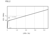
- FIG. 2 is a schematic diagram showing an example of a stress-strain curve different from that in FIG.
- FIG. 3 is a schematic diagram for explaining how to determine the yield point elongation when the upper yield point is not clear in the stress-strain curve.
- FIG. 4 is a plan view showing an example of a rotor core according to the present embodiment.
- FIG. 5 is a plan view showing an example of a stator core according to the present embodiment.
- FIG. 6 is a schematic diagram for explaining the definition of punching flatness in the dimensional accuracy evaluation test after punching in the embodiment.
- the inventors have investigated and examined the causes of the decrease in dimensional accuracy of punched products (rotor core materials, etc.) and the causes of the deterioration of magnetic properties when punching non-oriented electromagnetic steel sheets, which have high strength and excellent magnetic properties. As a result, the inventors have obtained the following findings.
- dislocations are introduced due to the shear strain imparted during punching.
- the introduced dislocations deteriorate the magnetic properties.
- the progression of work hardening means that the dislocations become entangled and remain in the steel sheet. Therefore, the iron loss of the steel sheet deteriorates further as work hardening progresses.
- the inventors further investigated ways to make the work hardening amount WH less than 15 MPa. As a result, the inventors obtained the following findings.
- Silicon (Si) restricts the slip systems through which dislocations can move. Increasing the Si content in steel sheet restricts the slip systems through which dislocations can move. This suppresses dislocation entanglement due to the occurrence of cross slip. As a result, the increase in dislocation density is suppressed.
- solute C and solute N in steel plate tend to adhere to dislocations. Dislocations to which solute C or N is adhered are difficult to move. Therefore, dislocations to which solute C or N is adhered tend to become entangled with moving dislocations. As a result, variations in dislocation density occur within the steel plate. In order to reduce such dislocations to which solute C or N is adhered, it is effective to reduce the amount of solute C and N in the steel plate.
- the inventors conducted an investigation from the viewpoint of chemical composition, and as a result, the inventors determined that the composition of the alloy should be, in mass %, Si: 3.1 to 4.5%, C: 0.0025% or less, N: 0.0025% or less, O: 0.0400% or less, P: 0.100% or less, S: 0.0050% or less, Ti: 0.0100% or less, Mn: 2.0% or less, Al: 1.500% or less, Zr: 0 to 0.0100%, Nb: 0 to 0.0100%, V: 0 to 0.0100%, Mo: 0 to 0.100%, Cr: 0 to 2.000%, La: 0 to 0.0100%, Ce: 0 to 0.0100%, B: 0 to 0.0010%, Zn: 0 to 0.0050%, G It was considered that a non-oriented electrical steel sheet having a chemical composition consisting of a: 0-0.0050%, Ge: 0-0.0050%, As: 0-0.0
- the amount of springback increases as work hardening progresses.
- the proportion of yield elongation, in which deformation progresses without work hardening is increased, the non-uniformity of deformation in the plate thickness direction is reduced, resulting in improved dimensional accuracy. If the yield elongation is 0.5% or more, the dimensional accuracy after punching is further improved.
- the yield elongation increases if the crystal grain size is reduced in order to increase the number of crystal grain boundaries, which are dislocation sources.
- the Si content in mass % of the non-oriented electrical steel sheet is substituted for Si in formula (4).
- the non-oriented electrical steel sheet of this embodiment was completed based on the above technical concept, and its gist is as follows:
- the non-oriented electrical steel sheet of the first configuration has the following composition, in mass %, Si: 3.1 to 4.5%, C: 0.0025% or less, N: 0.0025% or less, O: 0.0400% or less, P: 0.100% or less, S: 0.0050% or less, Ti: 0.0100% or less, Mn: 2.0% or less, Al: 1.500% or less, Zr: 0 to 0.0100%, Nb: 0 to 0.0100%, V: 0 to 0.0100%, Mo: 0 to 0.100%, Cr: 0 to 2.000%, La: 0 to 0.010 0%, Ce: 0-0.0100%, B: 0-0.0010%, Zn: 0-0.0050%, Ga: 0-0.0050%, Ge: 0-0.0050%, As: 0-0.0100%, Ni: 0-0.500%, Cu: 0-0.500%, Sn: 0-0.200%, Sb: 0-0.100%, Ca: 0-0.0050%, Nd:
- the non-oriented electrical steel sheet further has a tensile strength TS of greater than 570 MPa.
- the work hardening amount WH defined by formula (3) is less than 15 MPa.
- WH Y 2.0 -YS (3)
- the average grain size D ( ⁇ m) further satisfies the formula (4), and the yield elongation is 0.5% or more.
- D ⁇ 80-Si ⁇ 10 (4) In the formula (4), the element symbol is substituted with the content of the corresponding element in mass %. When the corresponding element is not contained, "0" is substituted for the element symbol.
- the non-oriented electrical steel sheet of the second configuration is a non-oriented electrical steel sheet of the first configuration, and contains, in mass%, Zr: 0.0001-0.0100%, Nb: 0.0001-0.0100%, V: 0.0001-0.0100%, Mo: 0.001-0.100%, Cr: 0.001-2.000%, La: 0.0001-0.0100%, Ce: 0.0001-0.0100%, B: 0.0001-0.0010%, Zn: 0.0001-0.0050%, Contains one or more selected from the group consisting of Ga: 0.0001-0.0050%, Ge: 0.0001-0.0050%, As: 0.0001-0.0100%, Ni: 0.001-0.500%, Cu: 0.001-0.500%, Sn: 0.001-0.200%, Sb: 0.001-0.100%, Ca: 0.0001-0.0050%, Nd: 0.0001-0.0010%, and Mg: 0.0001-0.0030%.
- the rotor core of the first configuration includes a plurality of rotor core blanks stacked together.
- the rotor core material is composed of, by mass%, Si: 3.1 to 4.5%, C: 0.0025% or less, N: 0.0025% or less, O: 0.0400% or less, P: 0.100% or less, S: 0.0050% or less, Ti: 0.0100% or less, Mn: 2.0% or less, Al: 1.500% or less, Zr: 0 to 0.0100%, Nb: 0 to 0.0100%, V: 0 to 0.0100%, Mo: 0 to 0.100%, Cr: 0 to 2.000%, La: 0 to 0.0100%, C e: 0-0.0100%, B: 0-0.0010%, Zn: 0-0.0050%, Ga: 0-0.0050%, Ge: 0-0.0050%, As: 0-0.0100%, Ni: 0-0.500%, Cu: 0-0.500%, Sn: 0-0.200%,
- the work hardening amount WH defined by formula (3) is less than 15 MPa.
- WH Y 2.0 -YS (3)
- the rotor core material has an average crystal grain size D ( ⁇ m) that satisfies formula (4) and a yield elongation of 0.5% or more. D ⁇ 80-Si ⁇ 10 (4)
- the element symbols in formula (4) are substituted with the corresponding element content in mass %. When the corresponding element is not contained, "0" is substituted for the element symbol.
- the rotor core of the second configuration is the rotor core of the first configuration, and the rotor core material has, in mass%, Zr: 0.0001-0.0100%, Nb: 0.0001-0.0100%, V: 0.0001-0.0100%, Mo: 0.001-0.100%, Cr: 0.001-2.000%, La: 0.0001-0.0100%, Ce: 0.0001-0.0100%, B: 0.0001-0.0010%, Zn: 0.0001-0.0050 %, Ga: 0.0001-0.0050%, Ge: 0.0001-0.0050%, As: 0.0001-0.0100%, Ni: 0.001-0.500%, Cu: 0.001-0.500%, Sn: 0.001-0.200%, Sb: 0.001-0.100%, Ca: 0.0001-0.0050%, Nd: 0.0001-0.0010%, and Mg: 0.0001-0.0030%.
- the motor of this embodiment has a rotor core of the first or second configuration.
- the method for producing a non-oriented electrical steel sheet of the present embodiment is a method for producing a non-oriented electrical steel sheet of the first or second configuration, and includes a hot rolling step, a cold rolling step, and a finish annealing step.
- the hot rolling process the slab is hot rolled to produce a hot-rolled steel sheet.
- the cold rolling process the hot-rolled steel sheet is cold-rolled to produce a cold-rolled steel sheet.
- the finish annealing process the cold-rolled steel sheet is subjected to finish annealing in a finish annealing furnace.
- the final annealing step the cold-rolled steel sheet is further annealed at a maximum temperature T1 of 950° C. or less.
- the tension TE applied to the cold-rolled steel sheet at the maximum temperature T1 is set to 2.0 to 10.0 MPa.
- the residence time t0 (seconds) between the annealing temperatures T1 and 700° C. in the heating zone, soaking zone, and cooling zone of the final annealing furnace, and the residence time t1 (seconds) between 700 and 500° C. in the cooling zone are set to satisfy formulas (A) and (B).
- the ratio of the water vapor partial pressure P H20 (atm) to the hydrogen partial pressure P H2 (atm) is made higher than 0.05, or the oxygen concentration is made higher than 0.010%.
- the temperature gradient CG in the longitudinal direction of the cold-rolled steel sheet during the cooling process is set to 20° C./m or less.
- the non-oriented electrical steel sheet of this embodiment is described in detail below.
- the non-oriented electrical steel sheet of the present embodiment satisfies the following features 1 to 5.
- the chemical composition, in mass%, is: Si: 3.1-4.5%, C: 0.0025% or less, N: 0.0025% or less, O: 0.0400% or less, P: 0.100% or less, S: 0.0050% or less, Ti: 0.0100% or less, Mn: 2.0% or less, Al: 1.500% or less, Zr: 0-0.0100%, Nb: 0-0.0100%, V: 0-0.0100%, Mo: 0-0.100%, Cr: 0-2.000%, La: 0-0.0 100%, Ce: 0-0.0100%, B: 0-0.0010%, Zn: 0-0.0050%, Ga: 0-0.0050%, Ge: 0-0.0050%, As: 0-0.0100%, Ni: 0-0.500%, Cu: 0-0.500%, Sn: 0-0.200%, Sb: 0-0
- the chemical composition of the non-oriented electrical steel sheet of this embodiment contains the following elements. Note that "%” regarding the element content in the chemical composition of the non-oriented electrical steel sheet and the rotor core material means mass % unless otherwise specified.
- the non-oriented electrical steel sheet is also simply referred to as "steel sheet”.
- Si 3.1-4.5%
- Silicon (Si) increases the resistivity of steel sheets and reduces eddy current loss. Silicon also dissolves in steel sheets to increase the strength of non-oriented electrical steel sheets. Silicon also forms slip systems through which dislocations can move. This makes it possible to suppress dislocation entanglement and to suppress an increase in dislocation density. Therefore, it is possible to improve the dimensional accuracy after punching. If the Si content is less than 3.1%, The effect is not sufficient. On the other hand, if the Si content exceeds 4.5%, the punching workability of the non-oriented electrical steel sheet decreases. Therefore, the Si content is 3.1 to 4.5%.
- the lower limit of the Si content is preferably 3.2%, more preferably 3.3%, and further preferably 3.4%.
- the upper limit of the Si content is preferably 4.4%, more preferably 4.3%, and further preferably 4.2%.
- Carbon (C) is unavoidably contained.
- the C content is more than 0%.
- C increases the strength of the steel plate.
- solute C is fixed to dislocations during punching, restricting the movement of dislocations. If there are many dislocations to which solute C is fixed, the density of dislocations entangled with each other also increases. As a result, unevenness is likely to occur in the punched product after punching, and the dimensional accuracy after punching decreases. If the C content exceeds 0.0025%, carbides and/or carbonitrides are generated in excessive amounts.
- the C content is 0.0025% or less.
- the lower limit of the C content is preferably 0.0001%, more preferably 0.0005%, more preferably 0.0010%, more preferably 0.0012%, more preferably 0.0014%, and more preferably 0.0016%.
- the upper limit of the C content is preferably 0.0024%, more preferably 0.0023%, further preferably 0.0022%, and further preferably 0.0021%.
- N 0.0025% or less Nitrogen (N) is unavoidably contained. In other words, the N content is more than 0%. N increases the strength of the steel sheet. Even if even a small amount of N is contained, the above effect can be obtained to a certain extent. However, if the N content exceeds 0.0025%, the amount of solute N in the steel sheet becomes excessively large. In this case, the solute N is fixed to the dislocations during punching, restricting the movement of the dislocations. If there are many dislocations to which the solute N is fixed, the density of dislocations entangled with each other also increases. As a result, the punched product after punching is likely to have unevenness, and the dimensional accuracy after punching is reduced.
- the N content is 0.0025% or less.
- the lower limit of the N content is preferably 0.0001%, more preferably 0.0005%, more preferably 0.0010%, more preferably 0.0012%, more preferably 0.0014%, and more preferably 0.0016%.
- the upper limit of the N content is preferably 0.0024%, more preferably 0.0023%, further preferably 0.0022%, and further preferably 0.0021%.
- O 0.0400% or less
- Oxygen (O) is unavoidably contained.
- the O content is more than 0%.
- O forms oxides and deteriorates the magnetic properties of the steel sheet. Therefore, the O content is 0.0400% or less.
- the O content is preferably as low as possible. However, excessive reduction in the O content increases the production cost. Therefore, from the viewpoint of industrial productivity, the lower limit of the O content is preferably 0.0001%, more preferably 0.0010%, and even more preferably 0.0020%.
- the upper limit of the O content is preferably 0.0370%, more preferably 0.0350%, further preferably 0.0300%, and further preferably 0.0200%.
- P 0.100% or less Phosphorus (P) is unavoidably contained.
- the P content is more than 0%.
- P increases the strength of the steel sheet. Even if even a small amount of P is contained, the above effect can be obtained to a certain extent.
- the P content exceeds 0.100%, the steel sheet becomes embrittled and the workability decreases, and cracks may occur in the steel sheet during cold rolling. Therefore, the P content is 0.100% or less.
- the lower limit of the P content is preferably 0.001%, more preferably 0.005%, and further preferably 0.007%.
- the upper limit of the P content is preferably 0.090%, more preferably 0.080%, and further preferably 0.070%.
- S 0.0050% or less Sulfur (S) is an unavoidable impurity.
- the S content is more than 0%.
- S generates MnS and deteriorates the core loss. Therefore, the S content is 0.0050% or less.
- the S content is preferably as low as possible. However, excessive reduction in the S content increases the production cost. Therefore, from the viewpoint of industrial productivity, the lower limit of the S content is preferably 0.0001%, more preferably 0.0003%, and further preferably 0.0005%.
- the upper limit of the S content is preferably 0.0047%, more preferably 0.0045%, still more preferably 0.0040%, still more preferably 0.0030%, still more preferably 0.0025%, and still more preferably 0.0020%.
- the chemical composition of the non-oriented electrical steel sheet of this embodiment further contains Ti: 0.0100% or less, Mn: 2.0% or less, Al: 1.500% or less, Zr: 0 to 0.0100%, Nb: 0 to 0.0100%, V: 0 to 0.0100%, Mo: 0 to 0.100%, Cr: 0 to 2.000%, La: 0 to 0.0100%, and Ce: 0 to 0.0100%. All of these elements fix the solute C and/or solute N in the steel sheet to form precipitates such as carbides, carbonitrides, or nitrides. As a result, these elements reduce the solute C and solute N that cause a decrease in dimensional accuracy after punching.
- Titanium (Ti) is inevitably contained.
- the Ti content is more than 0%.
- Ti combines with C and/or N to form precipitates, reducing the amount of dissolved C and N. This improves the dimensional accuracy after punching.
- Ti also increases the strength of the steel sheet by forming precipitates. Even if even a small amount of Ti is contained, the above effects can be obtained to a certain extent.
- the Ti content exceeds 0.0100%, excessive precipitates are formed, resulting in deterioration of the magnetic properties. Therefore, the Ti content is 0.0100% or less.
- the lower limit of the Ti content is preferably 0.0001%, more preferably 0.0005%, and further preferably 0.0010%.
- the upper limit of the Ti content is preferably 0.0090%, more preferably 0.0080%, further preferably 0.0070%, further preferably 0.0060%, and further preferably 0.0055%.
- Mn 2.0% or less Manganese (Mn) is inevitably contained.
- Mn combines with C to form carbides and reduce the amount of solute C.
- Mn also increases the resistivity of the steel sheet and reduces eddy current loss. Even if even a small amount of Mn is contained, the above effects can be obtained to a certain extent.
- the lower limit of the Mn content is preferably 0.1%, more preferably 0.2%, and further preferably 0.5%.
- the upper limit of the Mn content is preferably 1.8%, more preferably 1.6%, and further preferably 1.4%.
- Al 1.500% or less
- Aluminum (Al) is inevitably contained.
- the Al content is more than 0%.
- Al combines with N to form nitrides, reducing the amount of solute N. This improves the dimensional accuracy after punching.
- Al increases the strength of the steel sheet by forming nitrides. Even if even a small amount of Al is contained, the above effects can be obtained to a certain extent.
- the Al content exceeds 1.500%, an excessive amount of oxide is produced in the steel sheet, resulting in deterioration of the magnetic properties. Therefore, the Al content is not more than 1.500%.
- the lower limit of the Al content is preferably 0.001%, more preferably 0.004%, more preferably 0.005%, more preferably 0.010%, more preferably 0.050%, and more preferably 0.100%.
- the upper limit of the Al content is preferably 1.450%, more preferably 1.400%, further preferably 1.300%, further preferably 1.100%, and further preferably 0.900%.
- the Al content means the content of sol. Al (acid-soluble Al).
- Zr Zirconium (Zr) may not be contained, that is, the Zr content may be 0%.
- Zr When contained, that is, when the Zr content is more than 0%, Zr combines with C and/or N to form precipitates, reducing the amount of solute C and N. Zr improves the dimensional accuracy after punching. Zr also increases the strength of the steel sheet by forming precipitates. Even if only a small amount of Zr is contained, the above effects can be obtained to a certain extent. However, if the Zr content exceeds 0.0100%, excessive precipitates are formed, which deteriorates the magnetic properties. Therefore, the Zr content is 0 to 0.0100%.
- the lower limit of the Zr content is preferably 0.0001%, more preferably 0.0005%, and further preferably 0.0010%.
- the upper limit of the Zr content is preferably 0.0095%, more preferably 0.0090%, further preferably 0.0080%, and further preferably 0.0070%.
- Niobium (Nb) may not be contained, that is, the Nb content may be 0%.
- Nb When Nb is contained, it combines with C to form carbides and reduces the amount of solute C. As a result, Nb improves the dimensional accuracy after punching. Nb also reduces the strength of the steel sheet by forming carbides. The above effect can be obtained to some extent if even a small amount of Nb is contained. However, if the Nb content exceeds 0.0100%, carbides are formed in excess, which deteriorates the magnetic properties. Therefore, the Nb content is 0 to 0.0100%.
- the lower limit of the Nb content is preferably 0.0001%, more preferably 0.0005%, and further preferably 0.0010%.
- the upper limit of the Nb content is preferably 0.0090%, more preferably 0.0080%, still more preferably 0.0070%, still more preferably 0.0050%, and still more preferably 0.0040%. %, more preferably 0.0030%, and even more preferably 0.0025%.
- V 0 ⁇ 0.0100%
- Vanadium (V) may not be contained, that is, the V content may be 0%.
- V When V is contained, that is, when the V content is more than 0%, V combines with C to form carbides and reduces the amount of solute C. As a result, V improves the dimensional accuracy after punching. V also increases the strength of the steel sheet by forming carbides. Even if even a small amount of V is contained, the above effects can be obtained to a certain extent. However, if the V content exceeds 0.0100%, carbides are formed in excess, which deteriorates the magnetic properties. Therefore, the V content is 0 to 0.0100%.
- the lower limit of the V content is preferably 0.0001%, more preferably 0.0005%, and further preferably 0.0010%.
- the upper limit of the V content is preferably 0.0090%, more preferably 0.0080%, still more preferably 0.0070%, still more preferably 0.0050%, and still more preferably 0.0040%. %, more preferably 0.0030%, and even more preferably 0.0025%.
- Mo 0-0.100% Molybdenum (Mo) may not be contained, that is, the Mo content may be 0%.
- Mo When Mo is contained, that is, when the Mo content is more than 0%, Mo combines with C to form carbides and reduce the amount of solute C. As a result, Mo improves the dimensional accuracy after punching. Mo also increases the strength of the steel sheet by forming carbides. Even if even a small amount of Mo is contained, the above effects can be obtained to a certain extent. However, if the Mo content exceeds 0.100%, carbides are formed in excess, which deteriorates the magnetic properties. Therefore, the Mo content is 0 to 0.100%.
- the lower limit of the Mo content is preferably 0.001%, more preferably 0.005%, further preferably 0.010%, and further preferably 0.030%.
- the upper limit of the Mo content is preferably 0.090%, more preferably 0.080%, and further preferably 0.070%.
- Chromium (Cr) may not be contained, that is, the Cr content may be 0%.
- Cr When contained, that is, when the Cr content is more than 0%, Cr combines with C to form carbides, and reduces the amount of solute C. As a result, Cr improves the dimensional accuracy after punching. Cr also increases the strength of the steel sheet. Even if only a small amount of Cr is contained, the above effects can be obtained to a certain extent. However, if the Cr content exceeds 2.000%, excessive carbides are formed, which deteriorates the magnetic properties. Therefore, the Cr content is 0 to 2.000%.
- the lower limit of the Cr content is preferably 0.001%, more preferably 0.005%, further preferably 0.010%, and further preferably 0.050%.
- the upper limit of the Cr content is preferably 1.800%, more preferably 1.500%, further preferably 1.400%, and further preferably 1.000%.
- La 0 ⁇ 0.0100%
- Lanthanum (La) is an optional element and may not be contained. That is, the La content may be 0%. When contained, that is, when the La content is more than 0%, La bonds with N to form nitrides, reducing the amount of solute N. As a result, La reduces the dimensional accuracy after punching. La also increases the strength of the steel sheet by forming nitrides. If even a small amount of La is contained, the above effects can be obtained to a certain extent. However, if the La content exceeds 0.0100%, excessive nitrides are formed in the steel sheet, which deteriorates the magnetic properties. Therefore, the La content is 0 to 0.0100%.
- the lower limit of the La content is preferably 0.0001%, more preferably 0.0005%, further preferably 0.0010%, and further preferably 0.0020%.
- the upper limit of the La content is preferably 0.0090%, more preferably 0.0080%, further preferably 0.0075%, and further preferably 0.0070%.
- Ce 0 ⁇ 0.0100%
- Cerium (Ce) is an optional element and may not be contained, that is, the Ce content may be 0%.
- Ce When contained, that is, when the Ce content is more than 0%, Ce combines with N to form nitrides, reducing the amount of solute N. As a result, Ce reduces the dimensional accuracy after punching. Ce also increases the strength of the steel sheet by forming nitrides. Even if only a small amount of Ce is contained, the above effects can be obtained to a certain extent. However, if the Ce content exceeds 0.0100%, excessive nitrides are formed in the steel sheet, resulting in deterioration of the magnetic properties. Therefore, the Ce content is 0 to 0.0100%.
- the lower limit of the Ce content is preferably 0.0001%, more preferably 0.0005%, further preferably 0.0010%, and further preferably 0.0015%.
- the upper limit of the Ce content is preferably 0.0090%, more preferably 0.0080%, and further preferably 0.0070%.
- the remainder of the chemical composition of the non-oriented electrical steel sheet of this embodiment is composed of Fe and impurities.
- impurities are those that are mixed in from the raw materials, such as ore and scrap, or the manufacturing environment, when the non-oriented electrical steel sheet is industrially manufactured.
- the content of these impurities is permissible within a range that does not adversely affect the non-oriented electrical steel sheet of this embodiment.
- the non-oriented electrical steel sheet of this embodiment may further contain B: 0-0.0010%, Zn: 0-0.0050%, Ga: 0-0.0050%, Ge: 0-0.0050%, As: 0-0.0100%, Ni: 0-0.500%, Cu: 0-0.500%, Sn: 0-0.200%, Sb: 0-0.100%, Ca: 0-0.0050%, Nd: 0-0.0010%, and Mg: 0-0.0030%. All of these elements are optional and do not need to be contained. Each element is described below.
- B, Zn, Ga, Ge and As are impurities in the non-oriented electrical steel sheet of this embodiment.
- B 0-0.0010% Boron (B) is an optional element and may not be contained, that is, the B content may be 0%.
- B is contained, that is, when the B content is more than 0%, B forms nitrides, which inhibit recrystallization during final annealing. Therefore, the B content is 0 to 0.0010%.
- An excessive reduction in the B content increases the production cost. Therefore, from the viewpoint of industrial productivity, the lower limit of the B content is preferably 0.0001%, more preferably 0.0002%, and even more preferably 0. .0003%.
- the upper limit of the B content is preferably 0.0009%, more preferably 0.0008%, and further preferably 0.0007%.
- Zinc (Zn) is an optional element and may not be contained, that is, the Zn content may be 0%.
- Zn is contained, that is, when the Zn content exceeds 0%, no particular problem occurs so long as the Zn content is 0.0050% or less. Therefore, the Zn content is 0 to 0.0050%.
- An excessive reduction in the Zn content increases the production cost. Therefore, from the viewpoint of industrial productivity, the lower limit of the Zn content is preferably 0.0001%, more preferably 0.0002%, and even more preferably 0. .0003%.
- the upper limit of the Zn content is preferably 0.0020%, more preferably 0.0010%, and further preferably 0.0005%.
- Ga 0 to 0.0050%
- Ga is an optional element and may not be contained, that is, the Ga content may be 0%.
- the Ga content is 0 to 0.0050%. Excessive reduction in the Ga content increases the production cost. Therefore, from the viewpoint of industrial productivity, the lower limit of the Ga content is preferably 0.0001%, more preferably 0.0002%, and even more preferably 0. .0003%.
- the upper limit of the Ga content is preferably 0.0040%, more preferably 0.0035%, still more preferably 0.0030%, still more preferably 0.0020%, and still more preferably 0.0010%. %, and more preferably 0.0005%.
- Germanium (Ge) is an optional element and may not be contained, that is, the Ge content may be 0%.
- the Ge content is 0 to 0.0050%.
- the lower limit of the Ge content is preferably 0.0001%, more preferably 0.0002%, and even more preferably 0. .0003%.
- the upper limit of the Ge content is preferably 0.0040%, more preferably 0.0035%, still more preferably 0.0030%, still more preferably 0.0020%, and still more preferably 0.0010%. %, and more preferably 0.0005%.
- Arsenic (As) is an optional element and may not be contained, that is, the As content may be 0%.
- the As content When As is contained, that is, when the As content exceeds 0%, no particular problem occurs so long as the As content is 0.0100% or less. Therefore, the As content is 0 to 0.0100%. An excessive reduction in the As content increases the production cost. Therefore, from the viewpoint of industrial productivity, the lower limit of the As content is preferably 0.0001%, more preferably 0.0002%, and even more preferably 0. It is preferably 0.0003%, more preferably 0.0005%, and even more preferably 0.0010%.
- the upper limit of the As content is preferably 0.0070%, more preferably 0.0060%, further preferably 0.0050%, and further preferably 0.0030%.
- Ni and Cu are optional elements. Both Ni and Cu increase the strength of the non-oriented electrical steel sheet.
- Ni 0-0.500%
- Nickel (Ni) is an optional element and may not be contained, that is, the Ni content may be 0%.
- Ni When Ni is contained, that is, when the Ni content exceeds 0%, Ni increases the strength of the non-oriented electrical steel sheet. Even if even a small amount of Ni is contained, the above effect can be obtained to a certain degree. However, if the Ni content exceeds 0.500%, the steel sheet becomes embrittled and the workability decreases. Therefore, the Ni content is 0 to 0.500%.
- the lower limit of the Ni content is preferably 0.001%, more preferably 0.005%, still more preferably 0.010%, still more preferably 0.020%, and still more preferably 0.050%. %, and more preferably 0.100%.
- the upper limit of the Ni content is preferably 0.450%, more preferably 0.400%, still more preferably 0.350%, still more preferably 0.300%, and still more preferably 0.250%. %.
- Cu 0-0.500% Copper (Cu) is an optional element and may not be contained, that is, the Cu content may be 0%. When contained, that is, when the Cu content exceeds 0%, Cu increases the strength of the non-oriented electrical steel sheet. Even if even a small amount of Cu is contained, the above effect can be obtained to some extent. However, if the Cu content exceeds 0.500%, the steel sheet becomes embrittled and the workability decreases. Therefore, the Cu content is 0 to 0.500%.
- the lower limit of the Cu content is preferably 0.001%, more preferably 0.005%, still more preferably 0.010%, still more preferably 0.030%, and still more preferably 0.050%. %, and more preferably 0.100%.
- the upper limit of the Cu content is preferably 0.450%, more preferably 0.400%, still more preferably 0.350%, still more preferably 0.250%, and still more preferably 0.150%. %.
- Sn and Sb are optional elements. Both Sn and Sb reduce the core loss of the non-oriented electrical steel sheet.
- Tin (Sn) is an optional element and may not be contained, that is, the Sn content may be 0%.
- Sn segregates on the surface of the steel sheet and inhibits oxidation and nitridation during final annealing. Sn also improves the texture of the steel sheet.
- the magnetic flux density is increased by adding Sn, which reduces the core loss of the non-oriented electrical steel sheet. The above effect can be obtained to a certain extent if even a small amount of Sn is added. However, if the Sn content exceeds 0.200%, the steel sheet becomes embrittled and the workability decreases. Therefore, the Sn content is 0 to 0.200%.
- the lower limit of the Sn content is preferably 0.001%, more preferably 0.003%, still more preferably 0.005%, still more preferably 0.010%, and still more preferably 0.030%. %, and more preferably 0.050%.
- the upper limit of the Sn content is preferably 0.180%, more preferably 0.160%, further preferably 0.150%, and further preferably 0.120%.
- Sb 0-0.100%
- Antimony (Sb) is an optional element and may not be contained. In other words, the Sb content may be 0%.
- Sb is contained, that is, when the Sb content is more than 0%, Sb segregates on the surface of the steel sheet in the same manner as Sn, and suppresses oxidation and nitridation during final annealing. Sb also affects the texture of the steel sheet. This improves the magnetic flux density, thereby reducing the core loss of the non-oriented electrical steel sheet. Even if even a small amount of Sb is contained, the above effect can be obtained to a certain extent. However, if the Sb content exceeds 0.100%, the steel sheet becomes embrittled and the workability decreases.
- the Sb content is 0 to 0.100%.
- the lower limit of the Sb content is preferably 0.001%, more preferably 0.005%, further preferably 0.010%, and further preferably 0.030%.
- the upper limit of the Sb content is preferably 0.080%, more preferably 0.070%, further preferably 0.060%, and further preferably 0.050%.
- Ca, Nd and Mg are optional elements. All of Ca, Nd and Mg promote the growth of crystal grains during final annealing, thereby improving the magnetic properties of the non-oriented electrical steel sheet.
- Ca 0-0.0050% Calcium (Ca) is an optional element and may not be contained, that is, the Ca content may be 0%.
- Ca When contained, that is, when the Ca content is more than 0%, Ca combines with S during casting of molten steel to form coarse precipitates which are coarse sulfides and/or coarse oxysulfides.
- the grain size of the coarse precipitates is about 1 to 2 ⁇ m.
- the coarse precipitates adsorb inhibitors such as fine MnS, TiN, and AlN with grain sizes of about 100 nm that are generated in the steel plate during the manufacturing process after the casting process.
- the inhibition of crystal grain growth caused by the inhibitor is suppressed. Therefore, during final annealing, the growth of crystal grains is promoted.
- the magnetic properties of the non-oriented electrical steel sheet are improved. If it is contained, the above effects can be obtained to some extent. However, if the Ca content exceeds 0.0050%, coarse precipitates are formed in excess, which inhibits recrystallization and grain growth during the final annealing process. Therefore, the Ca content is 0 to 0.0050%.
- the lower limit of the Ca content is preferably 0.0001%, more preferably 0.0005%, and further preferably 0.0010%.
- the upper limit of the Ca content is preferably 0.0045%, more preferably 0.0040%, and further preferably 0.0035%.
- Neodymium is an optional element and may not be contained, that is, the Nd content may be 0%.
- Nd When Nd is contained, that is, when the Nd content is more than 0%, Nd generates coarse precipitates in the same manner as Ca, and suppresses the inhibition of grain growth caused by the inhibitor during the finish annealing. During annealing, the growth of crystal grains is promoted. As a result, the magnetic properties of the non-oriented electrical steel sheet are improved. Even if even a small amount of Nd is contained, the above effect can be obtained to a certain extent.
- the Nd content is 0 to 0.0010%.
- the lower limit of the Nd content is preferably 0.0001%, more preferably 0.0002%, and further preferably 0.0003%.
- the upper limit of the Nd content is preferably 0.0008%, more preferably 0.0006%, and further preferably 0.0004%.
- Mg 0-0.0030%
- Magnesium (Mg) is an optional element and may not be contained, that is, the Mg content may be 0%.
- Mg When Mg is contained, that is, when the Mg content is more than 0%, Mg generates coarse precipitates in the same manner as Ca, and suppresses the inhibition of grain growth caused by the inhibitor during the finish annealing. During annealing, the growth of crystal grains is promoted. As a result, the magnetic properties of the non-oriented electrical steel sheet are improved. Even if even a small amount of Mg is contained, the above effect can be obtained to a certain extent.
- the Mg content is 0 to 0.0030%.
- the lower limit of the Mg content is preferably 0.0001%, more preferably 0.0002%, and further preferably 0.0003%.
- the upper limit of the Mg content is preferably 0.0025%, more preferably 0.0020%, further preferably 0.0015%, and further preferably 0.0010%.
- the chemical composition of the non-oriented electrical steel sheet of this embodiment can be measured by a known component analysis method in accordance with JIS G0321:2017. Specifically, chips are collected from the steel sheet using a drill. The collected chips are dissolved in acid to obtain a solution. ICP-AES (Inductively Coupled Plasma Atomic Emission Spectrometry) is performed on the solution to perform elemental analysis of the chemical composition.
- the C content and S content are determined by a known high-frequency combustion method (combustion-infrared absorption method).
- the N content is determined by a known inert gas fusion-thermal conductivity method.
- the O content is determined by a known inert gas fusion-infrared absorption method.
- the content of each element is determined by rounding off the measured value based on the significant figures specified in this embodiment to the lowest digit of the content of each element specified in this embodiment.
- the Si content of the steel plate in this embodiment is specified as a value to one decimal place. Therefore, the Si content is determined as a value to one decimal place obtained by rounding off the measured value to one decimal place.
- the contents of other elements than the Si content of the steel plate of this embodiment are determined by rounding the measured value to the smallest digit specified in this embodiment, and the value obtained is the content of that element.
- Rounding means rounding down if the fraction is less than 5, and rounding up if the fraction is 5 or more.
- the non-oriented electrical steel sheet of the present embodiment further satisfies formula (1) and formula (2).
- the element symbols in formulas (1) and (2) are substituted with the corresponding element content in mass %. When the corresponding element is not contained, "0" is substituted for the element symbol.
- Formula (1) is a formula for sufficiently reducing solute C in a steel sheet by forming carbides or carbonitrides.
- the left side of formula (1) is composed of elements that bond with C to form carbides or carbonitrides. When formula (1) is satisfied, carbides or carbonitrides are sufficiently formed, and solute C is sufficiently reduced.
- Formula (2) is a formula for forming nitrides or carbonitrides to sufficiently reduce solute N.
- the left side of formula (2) is composed of elements that bond with N to form nitrides or carbonitrides.
- formula (2) is satisfied, nitrides or carbonitrides are sufficiently formed, and solute N is sufficiently reduced.
- the non-oriented electrical steel sheet of this embodiment has a tensile strength TS of more than 570 MPa, that is, the non-oriented electrical steel sheet of this embodiment has high strength.
- the lower limit of the tensile strength TS of the non-oriented electrical steel sheet of this embodiment is preferably 575 MPa, and more preferably 580 MPa.
- the upper limit of the tensile strength TS is not particularly limited. However, when the characteristics 1 and 2 are satisfied, the upper limit of the tensile strength TS is, for example, 750 MPa.
- the tensile strength TS of the non-oriented electrical steel sheet of this embodiment is measured by the following method.
- a JIS No. 5 tensile test piece specified in JIS Z2241:2011 is taken from the non-oriented electrical steel sheet.
- a tensile test is carried out at room temperature in air using the taken tensile test piece in accordance with JIS Z2241:2011 to obtain a stress-strain curve.
- the tensile strength TS (MPa) is determined from the obtained stress-strain curve.
- the amount of work hardening WH correlates with the dislocation density. If the amount of work hardening WH is less than 15 MPa, the dislocation density is sufficiently suppressed during punching. Therefore, the occurrence of dislocations in which solute C or solute N is fixed can be sufficiently suppressed. As a result, the occurrence of irregularities caused by the punching process is suppressed in the punched product after punching, and sufficient dimensional accuracy can be obtained.
- the upper limit of the work hardening amount WH is preferably 14 MPa, more preferably 13 MPa, more preferably 12 MPa, more preferably 11 MPa, and even more preferably 10 MPa. It is preferable that the work-hardening amount WH is as low as possible. In consideration of industrial productivity, the lower limit of the work-hardening amount WH is preferably 2 MPa, more preferably 1 MPa, and most preferably 0 MPa.
- Fig. 1 is a schematic diagram of an example of a stress-strain curve. Referring to Fig. 1, the maximum value of stress in the range of strain from 0 to 0.2% plastic strain is defined as "yield strength YS" (MPa). In Fig. 1, an upper yield point P0 occurs on the stress-strain curve when the strain is in the range L0 of 0 to 0.2% plastic strain. Therefore, when the stress-strain curve has an upper yield point as in Fig. 1, the stress at the upper yield point P0 is defined as the yield strength YS (MPa).
- the stress at 2.0% strain is designated as Y2.0 (MPa).
- the work hardening amount WH (MPa) is calculated according to formula (3).
- WH is defined as 0 (MPa).
- the average grain size D ( ⁇ m) satisfies the formula (4), and the yield elongation is 0.5% or more.
- the Si content in mass % in the chemical composition of the non-oriented electrical steel sheet is substituted for Si in formula (4).
- the lower limit of the average crystal grain size D is preferably 10 ⁇ m, more preferably 15 ⁇ m, and even more preferably 20 ⁇ m.
- a preferred upper limit of the average crystal grain size D is 75-Si ⁇ 10 ( ⁇ m), more preferably 70-Si ⁇ 10 ( ⁇ m), and even more preferably 65-Si ⁇ 10 ( ⁇ m).
- the lower limit of the yield elongation is preferably 0.6%, more preferably 0.7%, more preferably 1.0%, and even more preferably 1.5%.
- the upper limit of the yield elongation is not particularly limited, but is about 7.0%.
- the average grain size D is determined by the following method.
- a cross section (L cross section) parallel to the rolling direction of the non-oriented electrical steel sheet is used as the observation surface.
- the observation surface is mirror-polished, and then the mirror-polished observation surface is etched using a nital solution.
- the etched observation surface is observed at a magnification of 100 times using an optical microscope, and a photographic image of the observation field is generated.
- the average grain size D ( ⁇ m) is determined by a method of calculating the number of grains within a rectangular region described later in accordance with JIS G0551:2013 "Steel - Microscopic test method for grain size".
- a rectangular region consisting of only recrystallized grains, excluding unrecrystallized regions, is drawn, surrounded by lines parallel to the sheet thickness direction and the sheet surface direction (rolling direction).
- the rectangular region is the observation field.
- the area A of the rectangular region is set to 0.5 mm2 or more. If it is not possible to ensure an area of 0.5 mm2 or more for one rectangle, multiple rectangular regions are drawn so that the total area A of the rectangular regions is 0.5 mm2 or more.
- the number of crystal grains in the rectangular region is counted. Specifically, the number of crystal grains that exist inside the rectangular region and do not contact any side of the rectangular region is defined as N1. The number of crystal grains that intersect with any of the four sides of the rectangular region excluding the four corners (the four vertices of the rectangle) is defined as N2. The number of all rectangular regions drawn to ensure an area of 0.5 mm2 or more is defined as N3. The average crystal grain size D ( ⁇ m) is calculated using the total area A ( mm2 ) of the rectangular regions and the numbers of crystal grains N1 to N3 according to formula (I).
- the yield elongation is determined by the following method.
- a tensile test piece is taken from the non-oriented electrical steel sheet.
- a tensile test is carried out at room temperature in air in accordance with JIS Z2241:2011 to determine the yield elongation (%).
- a JIS No. 5 tensile test piece is used as the tensile test piece.
- the yield elongation (%) is determined by the following method.
- the yield strength YS MPa
- the strain value at the determined yield strength YS is designated as ⁇ 1.
- the maximum strain value ⁇ 2 in the region where the stress is maintained within the range of the yield stress YS ⁇ 1.0% as the strain increases is identified.
- the non-oriented electrical steel sheet of this embodiment satisfies Features 1 to 5. Therefore, the non-oriented electrical steel sheet of this embodiment has high strength and sufficient magnetic properties, and yet has excellent dimensional accuracy after punching.
- Step 1 Hot rolling step
- Step 2 Hot-rolled sheet annealing step
- Step 3 Cold rolling step
- Step 4 Finish annealing step
- step 2 is an optional step. In other words, step 2 does not have to be performed.
- Step 1 Hot rolling step
- the slab is hot rolled to produce a hot rolled steel sheet.
- the slab is produced by a known method, for example, a continuous casting method.
- Hot rolling is carried out on the prepared slab.
- the slab heating temperature is, for example, 1100 to 1200°C.
- the finish rolling temperature is, for example, 800 to 1100°C.
- the coiling temperature is, for example, 700 to 800°C.
- the hot-rolled sheet annealing process is an optional process. That is, the hot-rolled sheet annealing process may or may not be performed. When the hot-rolled sheet annealing process is performed, annealing is performed on the hot-rolled steel sheet.
- the hot-rolled sheet annealing may be box annealing or continuous annealing.
- the annealing conditions in the hot-rolled sheet annealing process are not particularly limited. In the case of box annealing, the annealing temperature is, for example, 750°C to 850°C, and the holding time at the annealing temperature is, for example, 1 hour to 30 hours.
- the annealing temperature is, for example, 900°C to 1000°C
- the holding time at the annealing temperature is, for example, 1 second to 100 seconds.
- a well-known pickling treatment may be performed on the hot-rolled steel sheet before annealing in the hot-rolled sheet annealing process and/or the hot-rolled steel sheet after annealing.
- Step 3 Cold rolling step
- the hot-rolled steel sheet produced in the hot rolling process or the hot-rolled steel sheet after the hot-rolled sheet annealing process is subjected to cold rolling to produce a cold-rolled steel sheet.
- Cold rolling may be performed once or multiple times.
- intermediate annealing may be performed after cold rolling before performing the next cold rolling.
- Step 4 Finish annealing step
- the cold-rolled steel sheet produced by the cold rolling process is subjected to finish annealing in a finish annealing furnace.
- the finish annealing the cold-rolled steel sheet finished to the final plate thickness is annealed to recrystallize and grow crystal grains.
- the following conditions 1 to 5 are satisfied.
- the steel sheet is annealed at a maximum temperature T1 (°C) of 950°C or less.
- the tension TE applied to the cold-rolled steel sheet at the maximum temperature T1 (° C.) is set to 2.0 to 10.0 MPa.
- the maximum reachable temperature T1 is set to 950°C or less. If the maximum reachable temperature T1 exceeds 950°C, solution of carbides and nitrides will occur in the steel plate. As a result, the work hardening amount WH defined by formula (3) will be 15 MPa or more. Therefore, the maximum reachable temperature T1 is 950°C or less. A known temperature is sufficient as the lower limit of the maximum reachable temperature T1. The lower limit of the maximum reachable temperature T1 is, for example, 800°C.
- the tension TE applied to the cold-rolled steel sheet at the maximum temperature T1 is set to 2.0 to 10.0 MPa. Specifically, the tension TE is applied in the rolling direction (longitudinal direction) of the cold-rolled steel sheet. If the tension TE is less than 2.0 MPa, dislocation sources are not sufficiently obtained in the steel sheet, and in this case, even if the formula (4) is satisfied in the non-oriented electrical steel sheet, the yield point elongation will be less than 0.5%. On the other hand, if the tension TE exceeds 10.0 MPa, residual strain occurs in the steel sheet. In this case, the work hardening amount WH becomes 15 MPa or more.
- the residence time t0 (seconds) between the annealing temperatures T1 and 700° C. in the heating zone, soaking zone, and cooling zone of the finish annealing furnace, and the residence time t1 (seconds) between 700 and 500° C. in the cooling zone satisfy the formulas (A) and (B).
- the residence time t0 includes the time from 700° C.
- the residence time t1 corresponds to the time from 700 to 500° C. in the cooling zone, and does not include the time from 500 to 700° C. in the heating process (heating zone).
- FA is greater than 0, that is, when the residence time t1 is longer than the residence time t0, the dissolved carbon and nitrogen can be fixed again as carbides, carbonitrides, and nitrides while suppressing the solution of the carbides and nitrides that were generated before the final annealing. Therefore, the dissolved C and dissolved N in the steel sheet can be reduced. As a result, the work hardening amount WH can be made less than 15 MPa.
- the ratio of the water vapor partial pressure P H20 (atm) to the hydrogen partial pressure P H2 (atm) is made higher than 0.05, or the oxygen concentration is made higher than 0.010%.
- the ratio of the water vapor partial pressure P H20 (atm) to the hydrogen partial pressure P H2 (atm) in the atmosphere of the finish annealing furnace is defined as the oxygen potential.
- the oxygen potential is higher than 0.05 or the oxygen concentration is higher than 0.010% in one or more locations selected from the heating zone, the soaking zone, and the cooling zone in the temperature range of 500°C or higher in the atmosphere of the finish annealing furnace, decarburization of the steel sheet during finish annealing is promoted. In this case, the solute C in the steel sheet can be sufficiently reduced.
- the work hardening amount WH can be made less than 15 MPa.
- Temperature gradient CG in the longitudinal direction of cold-rolled steel sheet during cooling In the cooling process, the temperature gradient in the longitudinal direction (rolling direction) of the cold-rolled steel sheet from the maximum temperature T1 to 500° C. is defined as CG (° C./m).
- the temperature gradient CG is calculated based on the sheet passing distance from the maximum temperature T1 to 500° C. and the temperature difference obtained by subtracting 500° C. from the maximum temperature T1. If the temperature gradient CG during the cooling process exceeds 20°C/m, residual strain will occur in the steel sheet due to thermal strain. In this case, the work hardening amount WH will be 15 MPa or more. Therefore, the temperature gradient CG is set to 20°C/m or less.
- a coating step may be performed after the final annealing step.
- an insulating coating is applied to the surface of the non-oriented electrical steel sheet after the final annealing.
- the type of the insulating coating is not particularly limited.
- the insulating coating may be an organic component or an inorganic component.
- the non-oriented electrical steel sheet of this embodiment can be manufactured by the above manufacturing method. Note that the manufacturing method of the non-oriented electrical steel sheet of this embodiment is not particularly limited as long as it satisfies Features 1 to 5.
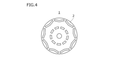
- Fig. 4 is a plan view showing an example of the rotor core 1.
- the rotor core 1 includes a plurality of rotor core blanks 2.
- the rotor core blanks 2 are plate-shaped. More specifically, the rotor core blanks 2 are disk-shaped.
- the rotor core 1 is configured by stacking the plurality of rotor core blanks 2.
- the shape of the rotor core material 2 is not particularly limited as long as it is plate-shaped.
- FIG. 4 shows the rotor core material 2 of a permanent magnet synchronous motor as an example.
- the rotor core material 2 may have other shapes as long as it is plate-shaped.
- the motor is a reluctance motor
- the rotor core material 2 may be plate-shaped with multiple salient poles, or may be plate-shaped with multiple through holes that serve as flux barriers.
- the motor is an induction motor
- the rotor core material 2 may have multiple through holes in which induced current paths made of copper or aluminum die casting, etc. are installed.
- the rotor core blank 2 is a punched product produced by punching the non-oriented electrical steel sheet of the present embodiment. Therefore, the rotor core blank 2 satisfies the above-mentioned features 1 to 5.
- the rotor core material 2 contains, in mass %, Si: 3.1 to 4.5%, C: 0.0025% or less, N: 0.0025% or less, O: 0.0400% or less, P: 0.100% or less, S: 0.0050% or less, Ti: 0.0100% or less, Mn: 2.0% or less, Al: 1.500% or less, Zr: 0 to 0.0100%, Nb: 0 to 0.0100%, V: 0 to 0.0100%, Mo: 0 to 0.100%, Cr: 0 to 2.000%, La: 0 to 0.010 0%, Ce: 0-0.0100%, B: 0-0.0010%, Zn: 0-0.0050%, Ga: 0-0.0050%, Ge: 0-0.0050%, As
- the work hardening amount WH defined by formula (3) is less than 15 MPa.
- WH Y 2.0 -YS (3)
- the average crystal grain size D ( ⁇ m) satisfies the formula (4), and the yield elongation is 0.5% or more.
- D ⁇ 80-Si ⁇ 10 (4) In the formula (4), the element symbol is substituted with the content of the corresponding element in mass %. When the corresponding element is not contained, "0" is substituted for the element symbol.
- a stator core may be manufactured using the non-oriented electromagnetic steel sheet of the present embodiment as a material.
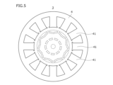
- Fig. 5 is a plan view of the stator core 3. Referring to Fig. 5, the stator core 3 includes a plurality of stator core blanks 4. The stator core blanks 4 are in the form of annular plates. The stator core 3 is configured by stacking the plurality of stator core blanks 4.
- the stator core material 4 includes a plurality of teeth 41.
- the teeth 41 are arranged with gaps between each other in the circumferential direction of the stator core material 4.
- Each tooth 41 extends in the radial direction of the stator core material 4.
- the stator core material 4 is manufactured by punching the non-oriented electromagnetic steel sheet of this embodiment, followed by stress relief annealing. Therefore, the stator core material 4 satisfies the above-mentioned features 1 and 2.
- the stator core material 4 contains, in mass %, Si: 3.1 to 4.5%, C: 0.0025% or less, N: 0.0025% or less, O: 0.0400% or less, P: 0.100% or less, S: 0.0050% or less, Ti: 0.0100% or less, Mn: 2.0% or less, Al: 1.500% or less, Zr: 0 to 0.0100%, Nb: 0 to 0.0100%, V: 0 to 0.0100%, Mo: 0 to 0.100%, Cr: 0 to 2.000%, La: 0 to 0.010 0%, Ce: 0-0.0100%, B: 0-0.0010%, Zn: 0-0.0050%, Ga: 0-0.0050%, Ge: 0-0.0050%, As: 0-0.0100%, Ni: 0-0.500%, Cu: 0-0.500%, Sn: 0-0.200%, Sb: 0-0.100%, Ca: 0-0.0050%, Nd: 0-0.0010%, M
- the chemical compositions of the rotor core material 2 and the stator core material 4 can be measured based on the method described in [Method for measuring the chemical composition of a non-oriented electrical steel sheet] above. Specifically, chips are collected from the rotor core material 2 or the stator core material 4 using a drill. The collected chips are dissolved in acid to obtain a solution. ICP-AES is performed on the solution to perform elemental analysis of the chemical composition.
- the C content and S content are determined by a well-known high-frequency combustion method (combustion-infrared absorption method).
- the N content is determined by a well-known inert gas fusion-thermal conductivity method.
- the O content is determined by a well-known inert gas fusion-infrared absorption method.
- the tensile strength TS of the rotor core blank 2 is measured by the following method.
- a JIS No. 5 tensile test piece specified in JIS Z2241:2011 is taken from the rotor core blank 2. If a JIS No. 5 tensile test piece cannot be taken because the size of the rotor core blank 2 is small, a scaled test piece of the JIS No. 5 tensile test piece is taken from the rotor core blank 2.
- a tensile test is carried out at room temperature in air in accordance with JIS Z2241:2011 to obtain a stress-strain curve.
- the tensile strength TS (MPa) is calculated from the obtained stress-strain curve.
- the work-hardening amount WH of the rotor core blank 2 is obtained by the method described in the above-mentioned [Work-hardening amount WH evaluation test].
- the stress-strain curve used is the stress-strain curve obtained by the above-mentioned [Method for measuring the stress-strain curve of the rotor core blank 2].
- the average crystal grain size D of the rotor core blank 2 is obtained by the method described in the above-mentioned [Method for measuring average crystal grain size D]. Note that a cross section (L cross section) of the rotor core blank 2 parallel to the rolling direction is used as the observation surface.
- the yield elongation of the rotor core blank 2 is determined by the following method. Specifically, a JIS No. 5 tensile test piece is taken from the rotor core blank 2. A tensile test is conducted at room temperature in air in accordance with JIS Z2241:2011 to determine the yield elongation (%). If a JIS No. 5 tensile test piece cannot be taken because the rotor core blank 2 is too small in size, a scaled-down version of the JIS No. 5 tensile test piece is taken from the rotor core blank 2. When a tensile test is conducted using the scaled-down version, the test is conducted based on the strain rate specified in Annex JB of the above standard.
- the yield elongation (%) is obtained by the following method.
- the yield strength YS MPa
- the strain value at the determined yield strength YS is designated as ⁇ 1.
- the maximum strain value ⁇ 2 in the region where the stress is maintained within the range of the yield stress YS ⁇ 1.0% as the strain increases is identified.
- the rotor core 1 is manufactured by the following method.
- the rotor core blank 2 is manufactured by punching from the non-oriented electrical steel sheet of this embodiment. Specifically, the rotor core blank 2 is punched out by punching. The punched rotor core blanks 2 are stacked to manufacture the rotor core 1.
- the motor of this embodiment includes the above-mentioned rotor core 1.
- the motor further includes a well-known stator core. Since the motor of this embodiment includes the rotor core of this embodiment, the rotor core has high strength and sufficient magnetic properties.
- the above-mentioned stator core 3 may be used as the stator core included in the motor core.
- the stator core 3 is manufactured by the following method.
- the non-oriented electromagnetic steel sheet of this embodiment is used as the material to manufacture the stator core blank 4 by punching.
- a plurality of stator core blanks 4 are stacked to manufacture the stator core 3.
- the stator core material 4 manufactured by punching the non-oriented electromagnetic steel sheet of this embodiment has high dimensional precision. Therefore, it has an advantage in terms of dimensional precision over conventional stator cores manufactured from non-oriented electromagnetic steel sheets with a tensile strength exceeding 570 MPa.
- the stator core 3 manufactured from the non-oriented electromagnetic steel sheet of this embodiment undergoes stress relief annealing after laminating the stator core material 4. This makes the motor incorporating the stator core 3 more efficient.
- Non-oriented electrical steel sheets having the chemical composition shown in Table 1 were manufactured using the following method.
- Hot rolling was performed on the slab (steel piece) to produce a hot-rolled steel sheet with a thickness of 2.0 mm.
- the slab heating temperature was 1100-1200°C.
- the finish rolling temperature was 800-1100°C.
- the coiling temperature was 700-800°C.
- the hot-rolled steel sheet was subjected to hot-rolled sheet annealing by continuous annealing, where the sheet was soaked at 1000°C for 60 seconds. After the hot-rolled sheet annealing, cold rolling was performed on the steel sheet to produce a cold-rolled steel sheet with a thickness of 0.25 mm.
- the cold-rolled steel sheets thus produced were subjected to finish annealing.
- the maximum temperature T1 (°C), tension TE (MPa), residence time t0 (sec) and residence time t1 (sec), FA, FB, oxygen potential P H20 /P H2 , oxygen concentration (%), and temperature gradient CG (°C/m) during the finish annealing are shown in Table 2.
- Non-oriented electrical steel sheets of each test number were produced by the above-mentioned production process.
- Test 1 The non-oriented electrical steel sheets having each test number were subjected to the following evaluation tests.
- Chemical composition measurement test (Test 2) Tensile strength TS measurement test (Test 3) Work hardening amount WH evaluation test (Test 4) Average grain size D measurement test (Test 5) Yield point elongation measurement test (Test 6) Magnetic property evaluation test (Test 7) Dimensional accuracy evaluation test after punching processing Tests 1 to 7 are explained below.
- Magnetic flux density B 50 (T) and iron loss W 5/1000 (W/kg) were determined by the following method.
- Magnetic flux density B50 evaluation test For the non-oriented electrical steel sheets of each test number, the magnetic flux density B 50 (L) in the rolling direction (L direction) and the magnetic flux density B 50 (C) in the direction perpendicular to the rolling direction (C direction) were measured. Specifically, Epstein test pieces were cut out in the L direction and the C direction from the non-oriented electrical steel sheets of each test number in accordance with JIS C 2550-1:2011.
- the magnetic steel strip test method in accordance with JIS C 2550-1:2011 and 2550-3:2011 was performed on the cut-out Epstein test pieces to measure the magnetic flux densities B 50 (L) (T) and B 50 (C) (T) at 5000 A/m in the L direction and the C direction.
- the arithmetic average of the magnetic flux density B 50 (L) (T) in the L direction and the magnetic flux density B 50 (C) in the C direction was taken as the magnetic flux density B 50 (T).
- the obtained magnetic flux density B 50 (T) is shown in Table 3.
- Epstein test pieces were prepared.
- the Epstein test pieces were cut out in two ways: by shear cutting with a clearance of 20 ⁇ m and by electric discharge machining. That is, two types of test pieces, Epstein test pieces cut out by shear cutting assuming punching and Epstein test pieces cut out by electric discharge machining, were prepared for each test number.
- the magnetic steel strip test method in accordance with JIS C 2550-1:2011 and 2550-3:2011 was performed to measure the iron loss W 5/1000 ( L) (W/kg) and iron loss W 5/1000 (C) (W/kg) at 1000 Hz and 0.5 T in the L direction (rolling direction) and C direction (direction perpendicular to the rolling direction).
- the arithmetic average value of the iron loss W 5/1000 (L) in the L direction (rolling direction) and the iron loss W 5/1000 (C) (W/kg) in the C direction (direction perpendicular to the rolling direction) was taken as the iron loss W 5/1000 (W/kg).
- the iron loss W 5/1000 (W/kg) in the Epstein test piece by shear cutting is shown in the "Shear cutting" column of "Iron loss W 5/1000 (W/kg)” in Table 3.
- the iron loss W 5/1000 (W/kg) in the Epstein test piece by electric discharge machining is shown in the "Electric discharge machining” column of "Iron loss W 5/1000 (W/kg)” in Table 3.
- the iron loss degradation amount ⁇ W 5/1000 (W/kg) was calculated by subtracting the iron loss W 5/1000 (W/kg) in the electric discharge machining from the iron loss W 5/1000 (W/kg) in the shear cutting.
- the iron loss degradation amount ⁇ iron loss W 5/1000 (W/kg) is shown in Table 3.
- the dimensional accuracy evaluation test after punching of the non-oriented electrical steel sheet of each test number was evaluated by the following test. From the non-oriented electrical steel sheet of each test number, a ring-shaped sample (punched product) with an inner diameter of 90 mm and an outer diameter of 100 mm was punched out with a die with a clearance of 8% of the sheet thickness. Furthermore, the ring-shaped sample prepared was cut at 45° intervals around the normal line of the non-oriented electrical steel sheet from the rolling direction of the non-oriented electrical steel sheet to obtain eight test pieces. Each test piece was filled with resin, and the cut surface was polished by 1 mm or more to remove the influence of deformation at the time of cutting.
- a line segment 20 is drawn connecting the point P1 where the sagging surface 10 switches to the punched end surface 11 and the burr tip P2 of the punched end surface 11.
- a line segment 21 is drawn that is parallel to the line segment 20 and tangent to the punched end surface 11 protruding from the line segment 20. The distance d between the line segment 20 and the line segment 21 is calculated.
- the arithmetic average value of the distances d calculated for eight test pieces was defined as the punched flatness ( ⁇ m).
- the obtained punched flatness is shown in Table 3 under "Punched Flatness ( ⁇ m)".
- Test Nos. 1 to 30 satisfied Features 1 to 5. Therefore, in the non-oriented electrical steel sheets with these test numbers, the magnetic flux density B50 was 1.60T or more, and the iron loss deterioration amount ⁇ W5 /1000 obtained by subtracting the iron loss W5/ 1000 in shear cutting from the iron loss W5/ 1000 in electric discharge machining was 2.0 or less, and excellent magnetic properties (magnetic flux density and iron loss) were obtained. Furthermore, the punching flatness was 25 ⁇ m or less, and the dimensional accuracy after punching was excellent.
- the Si content was too low. Therefore, the tensile strength TS was too low. Furthermore, the work hardening amount WH was 15 MPa or more. As a result, the iron loss deterioration amount ⁇ W 5/1000 was more than 2.0, and excellent magnetic properties were not obtained.
- the Si content was too low. Therefore, the work hardening amount WH was 15 MPa or more. As a result, the punching flatness exceeded 25 ⁇ m, and sufficient dimensional accuracy was not obtained during punching. Furthermore, the iron loss deterioration amount ⁇ W 5/1000 exceeded 2.0, and excellent magnetic properties were not obtained.
- Test Nos. 39 and 40 did not satisfy Condition 1 in the final annealing process. Therefore, the work hardening amount WH was 15 MPa or more. Furthermore, formula (4) was not satisfied, and the yield elongation was less than 0.5%. As a result, the punching flatness exceeded 25 ⁇ m, and sufficient dimensional accuracy was not obtained during punching. Furthermore, the iron loss deterioration amount ⁇ W 5/1000 exceeded 2.0, and excellent magnetic properties were not obtained.
- Test Nos. 49 and 50 did not satisfy Condition 4 in the final annealing process. Therefore, the work hardening amount WH was 15 MPa or more. As a result, the punching flatness exceeded 25 ⁇ m, and sufficient dimensional accuracy was not obtained during punching. Furthermore, the iron loss deterioration amount ⁇ W 5/1000 exceeded 2.0, and excellent magnetic properties were not obtained.
- the temperature gradient CG was too large. Therefore, the work hardening amount WH was 15 MPa or more. As a result, the punching flatness exceeded 25 ⁇ m, and sufficient dimensional accuracy was not obtained after punching. Furthermore, the iron loss deterioration amount ⁇ W 5/1000 exceeded 2.0, and excellent magnetic properties were not obtained.
- rotor cores having the shape shown in FIG. Specifically, a punching process was performed on the non-oriented electrical steel sheet of each test number. In the punching process, a rotor core blank was produced by punching with a die having a clearance of 8% of the sheet thickness. A rotor core blank was produced by stacking a plurality of rotor core blanks. The diameter of the rotor core blank was 70 mm.
- Test 1 Tensile strength TS measurement test (Test 2) Work hardening amount WH evaluation test (Test 3) Average crystal grain size D measurement test (Test 4) Yield point elongation measurement test (Test 5) Magnetic property evaluation test (Test 6) Dimensional accuracy evaluation test after punching processing Tests 1 to 6 are explained below.
- a line segment 21 is drawn that is parallel to the line segment 20 and in contact with the punched end surface 11 protruding from the line segment 20.
- the distance d between the line segment 20 and the line segment 21 is obtained.
- the arithmetic average value of the distance d obtained in the eight test pieces (total of eight pieces) was taken as the punching flatness ( ⁇ m).
- the punching flatness ( ⁇ m) of the obtained rotor core material is shown in Table 4.
- the punched end face at the time of punching is not maintained on the inner peripheral surface side of the rotor core blank due to processing at the time of inserting the shaft, etc. Therefore, as described above, the dimensional accuracy was evaluated on the punched end face in the vicinity of the outer peripheral surface of the rotor core blank.
- the rotor core materials with test numbers 1 to 30 satisfied features 1 to 5. Therefore, the rotor core materials with these test numbers had a punching flatness of 25 ⁇ m or less, and had excellent dimensional accuracy after punching. In addition, the rotor core materials had a magnetic flux density B 50 of 1.60 T or more and an iron loss W 5/1000 of 16.9 W/kg or less, and thus obtained high strength and excellent magnetic properties.
- non-oriented electrical steel sheet of the present disclosure is not limited to these examples. It is clear that a person skilled in the art can come up with various modified or revised examples within the scope of the ideas described in the claims, and it is understood that these naturally fall within the technical scope of the non-oriented electrical steel sheet of the present disclosure.
Landscapes
- Chemical & Material Sciences (AREA)
- Engineering & Computer Science (AREA)
- Materials Engineering (AREA)
- Organic Chemistry (AREA)
- Metallurgy (AREA)
- Mechanical Engineering (AREA)
- Physics & Mathematics (AREA)
- Electromagnetism (AREA)
- Thermal Sciences (AREA)
- Crystallography & Structural Chemistry (AREA)
- Manufacturing & Machinery (AREA)
- Power Engineering (AREA)
- Dispersion Chemistry (AREA)
- Manufacturing Of Steel Electrode Plates (AREA)
- Soft Magnetic Materials (AREA)
Priority Applications (6)
| Application Number | Priority Date | Filing Date | Title |
|---|---|---|---|
| EP24784979.7A EP4692400A1 (en) | 2023-04-07 | 2024-04-05 | Non-oriented electrical steel sheet, rotor core, motor, and method for producing non-oriented electrical steel sheet |
| CN202480023866.6A CN121002208A (zh) | 2023-04-07 | 2024-04-05 | 无取向性电磁钢板、转子铁芯、电机、以及无取向性电磁钢板的制造方法 |
| US19/472,750 US20260117338A1 (en) | 2023-04-07 | 2024-04-05 | Non-oriented electrical steel sheet, rotor core, motor, and method for producing non-oriented electrical steel sheet |
| KR1020257036880A KR20250163993A (ko) | 2023-04-07 | 2024-04-05 | 무방향성 전자 강판, 로터 코어, 모터, 및 무방향성 전자 강판의 제조 방법 |
| JP2025513192A JP7776796B2 (ja) | 2023-04-07 | 2024-04-05 | 無方向性電磁鋼板、ロータコア、モータ、及び、無方向性電磁鋼板の製造方法 |
| MX2025011884A MX2025011884A (es) | 2023-04-07 | 2025-10-03 | Hoja de acero electrico no orientado, nucleo de rotor, motor y metodo para fabricar hoja de acero electrico no orientado |
Applications Claiming Priority (2)
| Application Number | Priority Date | Filing Date | Title |
|---|---|---|---|
| JP2023062516 | 2023-04-07 | ||
| JP2023-062516 | 2023-04-07 |
Publications (1)
| Publication Number | Publication Date |
|---|---|
| WO2024210197A1 true WO2024210197A1 (ja) | 2024-10-10 |
Family
ID=92972147
Family Applications (1)
| Application Number | Title | Priority Date | Filing Date |
|---|---|---|---|
| PCT/JP2024/014046 Ceased WO2024210197A1 (ja) | 2023-04-07 | 2024-04-05 | 無方向性電磁鋼板、ロータコア、モータ、及び、無方向性電磁鋼板の製造方法 |
Country Status (8)
| Country | Link |
|---|---|
| US (1) | US20260117338A1 (https=) |
| EP (1) | EP4692400A1 (https=) |
| JP (1) | JP7776796B2 (https=) |
| KR (1) | KR20250163993A (https=) |
| CN (1) | CN121002208A (https=) |
| MX (1) | MX2025011884A (https=) |
| TW (1) | TWI892568B (https=) |
| WO (1) | WO2024210197A1 (https=) |
Cited By (1)
| Publication number | Priority date | Publication date | Assignee | Title |
|---|---|---|---|---|
| WO2025229787A1 (ja) * | 2024-05-02 | 2025-11-06 | 日本製鉄株式会社 | 無方向性電磁鋼板、モータコアおよびモータ |
Citations (6)
| Publication number | Priority date | Publication date | Assignee | Title |
|---|---|---|---|---|
| JP2002294414A (ja) * | 2001-03-29 | 2002-10-09 | Nkk Corp | 加工性に優れた無方向性電磁鋼板およびその製造方法 |
| JP2005105407A (ja) * | 2003-09-10 | 2005-04-21 | Nippon Steel Corp | 磁気特性と打ち抜き加工性に優れた無方向性電磁鋼板 |
| JP2008050686A (ja) | 2006-07-27 | 2008-03-06 | Nippon Steel Corp | 強度と磁気特性に優れた無方向性電磁鋼板とその製造方法 |
| JP2018178196A (ja) * | 2017-04-14 | 2018-11-15 | 新日鐵住金株式会社 | 無方向性電磁鋼板及びその製造方法 |
| JP2019178372A (ja) * | 2018-03-30 | 2019-10-17 | 日本製鉄株式会社 | 無方向性電磁鋼板およびその製造方法、並びにモータコアおよびその製造方法 |
| WO2023282071A1 (ja) * | 2021-07-05 | 2023-01-12 | Jfeスチール株式会社 | 無方向性電磁鋼板とその製造方法 |
Family Cites Families (2)
| Publication number | Priority date | Publication date | Assignee | Title |
|---|---|---|---|---|
| JP6500980B2 (ja) * | 2015-04-27 | 2019-04-17 | 日本製鉄株式会社 | 無方向性電磁鋼板 |
| BR112023019274A2 (pt) * | 2021-03-31 | 2023-10-24 | Nippon Steel Corp | Chapa de aço elétrico não orientada, métodos para |
-
2024
- 2024-04-05 CN CN202480023866.6A patent/CN121002208A/zh active Pending
- 2024-04-05 JP JP2025513192A patent/JP7776796B2/ja active Active
- 2024-04-05 KR KR1020257036880A patent/KR20250163993A/ko active Pending
- 2024-04-05 EP EP24784979.7A patent/EP4692400A1/en active Pending
- 2024-04-05 WO PCT/JP2024/014046 patent/WO2024210197A1/ja not_active Ceased
- 2024-04-05 US US19/472,750 patent/US20260117338A1/en active Pending
- 2024-04-08 TW TW113112979A patent/TWI892568B/zh active
-
2025
- 2025-10-03 MX MX2025011884A patent/MX2025011884A/es unknown
Patent Citations (6)
| Publication number | Priority date | Publication date | Assignee | Title |
|---|---|---|---|---|
| JP2002294414A (ja) * | 2001-03-29 | 2002-10-09 | Nkk Corp | 加工性に優れた無方向性電磁鋼板およびその製造方法 |
| JP2005105407A (ja) * | 2003-09-10 | 2005-04-21 | Nippon Steel Corp | 磁気特性と打ち抜き加工性に優れた無方向性電磁鋼板 |
| JP2008050686A (ja) | 2006-07-27 | 2008-03-06 | Nippon Steel Corp | 強度と磁気特性に優れた無方向性電磁鋼板とその製造方法 |
| JP2018178196A (ja) * | 2017-04-14 | 2018-11-15 | 新日鐵住金株式会社 | 無方向性電磁鋼板及びその製造方法 |
| JP2019178372A (ja) * | 2018-03-30 | 2019-10-17 | 日本製鉄株式会社 | 無方向性電磁鋼板およびその製造方法、並びにモータコアおよびその製造方法 |
| WO2023282071A1 (ja) * | 2021-07-05 | 2023-01-12 | Jfeスチール株式会社 | 無方向性電磁鋼板とその製造方法 |
Non-Patent Citations (1)
| Title |
|---|
| See also references of EP4692400A1 |
Cited By (1)
| Publication number | Priority date | Publication date | Assignee | Title |
|---|---|---|---|---|
| WO2025229787A1 (ja) * | 2024-05-02 | 2025-11-06 | 日本製鉄株式会社 | 無方向性電磁鋼板、モータコアおよびモータ |
Also Published As
| Publication number | Publication date |
|---|---|
| US20260117338A1 (en) | 2026-04-30 |
| TW202444934A (zh) | 2024-11-16 |
| JP7776796B2 (ja) | 2025-11-27 |
| EP4692400A1 (en) | 2026-02-11 |
| KR20250163993A (ko) | 2025-11-21 |
| MX2025011884A (es) | 2025-11-03 |
| CN121002208A (zh) | 2025-11-21 |
| JPWO2024210197A1 (https=) | 2024-10-10 |
| TWI892568B (zh) | 2025-08-01 |
Similar Documents
| Publication | Publication Date | Title |
|---|---|---|
| US11124854B2 (en) | Non-oriented electrical steel sheet and method for manufacturing non-oriented electrical steel sheet | |
| KR101508082B1 (ko) | 무방향성 전기 강판의 제조 방법 | |
| JP6617857B1 (ja) | 無方向性電磁鋼板およびその製造方法 | |
| CN108368584A (zh) | 无取向电工钢板及其制造方法 | |
| JP7303476B2 (ja) | 無方向性電磁鋼板、モータコア、無方向性電磁鋼板の製造方法及びモータコアの製造方法 | |
| CN101310034B (zh) | 高强度无方向性电磁钢板及其制造方法 | |
| CN103392021A (zh) | 无方向性电磁钢板及其制造方法 | |
| JP5223190B2 (ja) | 無方向性電磁鋼板およびその製造方法 | |
| JP7776796B2 (ja) | 無方向性電磁鋼板、ロータコア、モータ、及び、無方向性電磁鋼板の製造方法 | |
| JP5028992B2 (ja) | 無方向性電磁鋼板およびその製造方法 | |
| JP7231116B2 (ja) | 無方向性電磁鋼板およびその製造方法 | |
| JP2011089204A (ja) | 回転子用無方向性電磁鋼板およびその製造方法 | |
| JP2007254801A (ja) | 高強度無方向性電磁鋼板およびその製造方法 | |
| CA3288198A1 (en) | Non-oriented electrical steel sheet, rotor core, motor, and method for producing non-oriented electrical steel sheet | |
| US20260110047A1 (en) | Non-oriented electrical steel sheet and method for producing same | |
| TWI881720B (zh) | 無方向性電磁鋼板 | |
| TWI870238B (zh) | 無方向性電磁鋼板 | |
| WO2025159168A1 (ja) | 無方向性電磁鋼板、ロータコア、ステータコア、及び、モータ | |
| CN118434896A (zh) | 无方向性电磁钢板 | |
| CN120513313A (zh) | 无取向性电磁钢板 |
Legal Events
| Date | Code | Title | Description |
|---|---|---|---|
| 121 | Ep: the epo has been informed by wipo that ep was designated in this application |
Ref document number: 24784979 Country of ref document: EP Kind code of ref document: A1 |
|
| ENP | Entry into the national phase |
Ref document number: 2025513192 Country of ref document: JP Kind code of ref document: A |
|
| WWE | Wipo information: entry into national phase |
Ref document number: 2025513192 Country of ref document: JP |
|
| REG | Reference to national code |
Ref country code: BR Ref legal event code: B01A Ref document number: 112025020093 Country of ref document: BR |
|
| WWE | Wipo information: entry into national phase |
Ref document number: 2501006733 Country of ref document: TH |
|
| WWE | Wipo information: entry into national phase |
Ref document number: MX/A/2025/011884 Country of ref document: MX |
|
| WWE | Wipo information: entry into national phase |
Ref document number: 202517100117 Country of ref document: IN |
|
| WWP | Wipo information: published in national office |
Ref document number: MX/A/2025/011884 Country of ref document: MX |
|
| ENP | Entry into the national phase |
Ref document number: 1020257036880 Country of ref document: KR Free format text: ST27 STATUS EVENT CODE: A-0-1-A10-A15-NAP-PA0105 (AS PROVIDED BY THE NATIONAL OFFICE) |
|
| WWE | Wipo information: entry into national phase |
Ref document number: KR1020257036880 Country of ref document: KR |
|
| WWE | Wipo information: entry into national phase |
Ref document number: 2025129678 Country of ref document: RU Ref document number: 2024784979 Country of ref document: EP |
|
| NENP | Non-entry into the national phase |
Ref country code: DE |
|
| ENP | Entry into the national phase |
Ref document number: 2024784979 Country of ref document: EP Effective date: 20251107 |
|
| ENP | Entry into the national phase |
Ref document number: 2024784979 Country of ref document: EP Effective date: 20251107 |
|
| WWE | Wipo information: entry into national phase |
Ref document number: 11202506673U Country of ref document: SG |
|
| WWP | Wipo information: published in national office |
Ref document number: 11202506673U Country of ref document: SG |
|
| ENP | Entry into the national phase |
Ref document number: 2024784979 Country of ref document: EP Effective date: 20251107 |
|
| WWP | Wipo information: published in national office |
Ref document number: 2025129678 Country of ref document: RU |
|
| ENP | Entry into the national phase |
Ref document number: 2024784979 Country of ref document: EP Effective date: 20251107 |
|
| ENP | Entry into the national phase |
Ref document number: 2024784979 Country of ref document: EP Effective date: 20251107 |
|
| ENP | Entry into the national phase |
Ref document number: 2024784979 Country of ref document: EP Effective date: 20251107 |
|
| WWP | Wipo information: published in national office |
Ref document number: 202517100117 Country of ref document: IN |
|
| ENP | Entry into the national phase |
Ref document number: 2024784979 Country of ref document: EP Effective date: 20251107 |
|
| ENP | Entry into the national phase |
Ref document number: 2024784979 Country of ref document: EP Effective date: 20251107 |
|
| WWP | Wipo information: published in national office |
Ref document number: 2024784979 Country of ref document: EP |