WO2024209984A1 - 蓄電デバイス用外装材 - Google Patents
蓄電デバイス用外装材 Download PDFInfo
- Publication number
- WO2024209984A1 WO2024209984A1 PCT/JP2024/011762 JP2024011762W WO2024209984A1 WO 2024209984 A1 WO2024209984 A1 WO 2024209984A1 JP 2024011762 W JP2024011762 W JP 2024011762W WO 2024209984 A1 WO2024209984 A1 WO 2024209984A1
- Authority
- WO
- WIPO (PCT)
- Prior art keywords
- layer
- exterior material
- less
- resin
- sealant layer
- Prior art date
- Legal status (The legal status is an assumption and is not a legal conclusion. Google has not performed a legal analysis and makes no representation as to the accuracy of the status listed.)
- Pending
Links
Images
Classifications
-
- Y—GENERAL TAGGING OF NEW TECHNOLOGICAL DEVELOPMENTS; GENERAL TAGGING OF CROSS-SECTIONAL TECHNOLOGIES SPANNING OVER SEVERAL SECTIONS OF THE IPC; TECHNICAL SUBJECTS COVERED BY FORMER USPC CROSS-REFERENCE ART COLLECTIONS [XRACs] AND DIGESTS
- Y02—TECHNOLOGIES OR APPLICATIONS FOR MITIGATION OR ADAPTATION AGAINST CLIMATE CHANGE
- Y02E—REDUCTION OF GREENHOUSE GAS [GHG] EMISSIONS, RELATED TO ENERGY GENERATION, TRANSMISSION OR DISTRIBUTION
- Y02E60/00—Enabling technologies; Technologies with a potential or indirect contribution to GHG emissions mitigation
- Y02E60/10—Energy storage using batteries
Definitions
- This disclosure relates to exterior materials for electricity storage devices.
- power storage devices include secondary batteries such as lithium ion batteries, nickel metal hydride batteries, and lead acid batteries, as well as electrochemical capacitors such as electric double layer capacitors.
- secondary batteries such as lithium ion batteries, nickel metal hydride batteries, and lead acid batteries
- electrochemical capacitors such as electric double layer capacitors.
- metal cans were used as the exterior material for lithium ion batteries, but multilayer films, which are lightweight, have high heat dissipation properties, and can be produced at low cost, are now being used.
- a lithium ion battery that uses the above multilayer film as an exterior material is called a laminated lithium ion battery.
- a laminated lithium ion battery includes an energy storage element with a positive electrode, a liquid electrolyte, and a negative electrode, and an exterior bag that houses the energy storage element, and prevents moisture from penetrating into the battery.
- the exterior bag has an exterior material, and the exterior material includes a base layer, a barrier layer, an adhesive layer, and a sealant layer, in that order. The exterior material covers the energy storage element with the sealant layer facing inward and the base layer facing outward.
- a laminated lithium ion battery is manufactured, for example, by forming a recess in part of the exterior material by cold molding, housing the energy storage element in the recess, folding back the remaining part of the exterior material, and heat sealing the edges (see, for example, Patent Document 1).
- An all-solid-state battery includes, for example, an energy storage element and an outer bag that houses the energy storage element.
- An all-solid-state battery the expansion or contraction of the negative electrode and positive electrode accompanying charging and discharging can cause peeling between the solid electrolyte and the positive electrode active material, or between the solid electrolyte and the negative electrode active material. This can lead to insufficient output from the all-solid-state battery.
- the energy storage element can be pressurized via the outer bag. However, if excessive deformation of the outer bag occurs due to the pressurization, uniform pressure cannot be applied to the energy storage element via the outer bag.
- the temperature range of the all-solid-state battery is, for example, from -40°C to 100°C. This range is wider than the temperature range of a liquid lithium-ion battery (for example, from -40°C to 60°C).
- a high-temperature environment for example, 70°C or higher
- the above-mentioned deformation of the outer bag is likely to occur. Therefore, even when an all-solid-state battery is used in a high-temperature environment, there is a risk that the output of the all-solid-state battery will be insufficient.
- One aspect of the present disclosure aims to provide an exterior material for an electricity storage device that is resistant to excessive deformation even when pressurized in a high-temperature environment.
- the exterior material for an electricity storage device comprises a base layer, a barrier layer, a thermal adhesive resin layer or adhesive layer, and a sealant layer, which are laminated in this order.
- the thermal adhesive resin layer and the sealant layer, or the sealant layer are (I) and the base layer is (II)
- the loop stiffness value of (I) is 10 mN or more and 80 mN or less
- the loop stiffness value of (II) is 2 mN or more and 20 mN or less
- the loop stiffness value ratio (I/II) of (I) to (II) is 1.0 or more and 15 or less
- the thickness ratio (I/II) of (I) to (II) is 1.0 or more and 8.0 or less.
- the ratio (I/II) of the loop stiffness value of (I) to (II) is 1.0 or more and 15 or less, and the ratio (I/II) of the thickness of (I) to (II) is 1.0 or more and 8.0 or less.
- the thickness of (I) above may be 30 ⁇ m or more and 120 ⁇ m or less, and the thickness of (II) above may be 10 ⁇ m or more and 60 ⁇ m or less. In this case, the durability of the exterior material can be ensured while keeping the thickness of the exterior material low. In addition, the loop stiffness value of (I) above and the loop stiffness value of (II) above can each be reliably set within the above range.
- the ratio (I/II) of the loop stiffness values of (I) and (II) may be 2.5 or more and 11.0 or less. In this case, deformation of the exterior material for an electricity storage device is further suppressed even when pressure is applied in a high-temperature environment.
- the ratio (I/II) of the loop stiffness values of (I) and (II) above may be 3.5 or more and 10 or less.
- the ratio (I/II) of the loop stiffness values of (I) and (II) above may be 8.0 or more and 9.0 or less. In these cases, deformation of the exterior material for an electricity storage device is better suppressed even when pressure is applied in a high-temperature environment.
- the sealant layer contains a polypropylene-based resin as a base resin, and the polypropylene-based resin may be composed of homopropylene or block polypropylene. In this case, melting of the sealant layer in a high-temperature environment can be suppressed.
- the sealant layer may further contain an additive resin including a polyethylene-based resin, or a block copolymer that is compatible with the polypropylene-based resin.
- an additive resin including a polyethylene-based resin, or a block copolymer that is compatible with the polypropylene-based resin.
- the content of the additive resin or block copolymer in the sealant layer may be 10% by mass or more and 20% by mass or less. In this case, deformation of the exterior material for the electric storage device is further suppressed.
- the sealant layer may further contain an additive resin containing a polyethylene-based resin, and a compatibilizer having a portion compatible with the polypropylene-based resin and a portion compatible with the polyethylene-based resin.
- an additive resin containing a polyethylene-based resin and a compatibilizer having a portion compatible with the polypropylene-based resin and a portion compatible with the polyethylene-based resin.
- the total content of the additive resin and the compatibilizer in the sealant layer may be 10% by mass or more and 20% by mass or less. In this case, deformation of the exterior material for the electric storage device is even more effectively suppressed.
- the compatibilizer may include a block copolymer of polypropylene and polyethylene, or a block copolymer of polyethylene and polyethylenebutylene.
- the exterior material for the power storage device may be an exterior material for an all-solid-state battery.
- the exterior material for the power storage device is highly suitable as an exterior material for an all-solid-state battery because it can suppress deformation even when pressurized in a high-temperature environment.
- This disclosure makes it possible to provide an exterior material for an electricity storage device that is resistant to excessive deformation even when pressurized in a high-temperature environment.
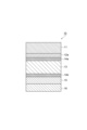
- FIG. 1 is a schematic cross-sectional view of an exterior material for an electricity storage device according to one embodiment.
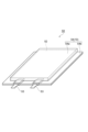
- FIG. 2 is a perspective view illustrating an electricity storage device according to one embodiment.
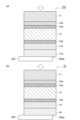
- FIG. 3(a) is a schematic cross-sectional view of a comparative exterior material when pressed against a rigid body
- FIG. 3(b) is a schematic cross-sectional view of an exterior material for an electricity storage device according to one embodiment when pressed against a rigid body.
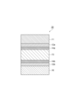
- FIG. 4 is a schematic cross-sectional view of an exterior material for an electricity storage device according to a modified example.
- FIG. 1 is a schematic cross-sectional view of an exterior material for a power storage device according to an embodiment.
- an exterior material 10 (exterior material for a power storage device) according to an embodiment is an exterior material used for a power storage device, and includes a base layer 11, a barrier layer 13, a thermal adhesive resin layer 15, and a sealant layer 16, which are laminated in this order.
- the loop stiffness value of (I) is 10 mN or more and 80 mN or less
- the loop stiffness value of (II) is 2 mN or more and 20 mN or less
- the ratio (I/II) of the loop stiffness values of (I) and (II) is 1.0 or more and 15 or less
- the thickness ratio (I/II) of (I) and (II) is 1.0 or more and 8.0 or less.
- the barrier layer 13 has a first corrosion prevention treatment layer 14a on the substrate layer 11 side via a first adhesive layer 12a, and a second corrosion prevention treatment layer 14b on the sealant layer 16 side.
- the substrate layer 11 is the outermost layer and the sealant layer 16 is the innermost layer in the exterior packaging material 10.
- the exterior packaging material 10 is used with the substrate layer 11 facing the outside of the electricity storage device and the sealant layer 16 facing the inside of the electricity storage device.
- the base material layer 11 imparts heat resistance in a sealing step when manufacturing an electricity storage device, and plays a role in suppressing the occurrence of pinholes that may occur during molding, distribution, etc.
- it can also impart scratch resistance, chemical resistance, insulation, etc.
- the substrate layer 11 is, for example, a layer formed of a resin having insulating properties.
- resins that can be used include polyester resin, polyamide resin, polyimide resin, polyamideimide resin, polyetherketone resin, polyphenylene sulfide resin, polyetherimide resin, polysulfone resin, fluororesin, phenolic resin, melamine resin, urethane resin, allyl resin, silicone resin, epoxy resin, furan resin, and acetylcellulose resin.
- the base layer 11 may be formed from a polyester resin or a polyamide resin from the viewpoint of moldability.
- polyester resins include polyethylene terephthalate, polybutylene terephthalate, and polyethylene naphthalate.
- polyamide resins include nylon 6, nylon 6,6, a copolymer of nylon 6 and nylon 6,6, nylon 9T, nylon 10, polymetaxylylene adipamide (MXD6), nylon 11, and nylon 12.
- the substrate layer 11 may be in the form of a stretched or unstretched film, or in the form of a coating film.
- the substrate layer 11 may be a single layer or a multilayer. When the substrate layer 11 is a multilayer, it is formed by laminating layers made of different resins. When the substrate layer 11 is in the form of a film, it may be a co-extruded film or a laminated film using an adhesive. When the substrate layer 11 is a coating film, it may be a coating film obtained by applying a coating film-forming composition multiple times.
- the substrate layer 11 may also be a multilayer film formed by combining a film and a coating film.
- the base layer 11 may be a biaxially stretched film.
- the moldability of the exterior material 10 is improved.
- the stretching method for the biaxially stretched film include sequential biaxial stretching, tubular biaxial stretching, and simultaneous biaxial stretching.
- the biaxially stretched film may be a film stretched by the tubular biaxial stretching method from the viewpoint of obtaining better deep-draw moldability.
- the thickness of the substrate layer 11 is 10 ⁇ m or more and 60 ⁇ m or less.
- the thickness of the substrate layer 11 may be 15 ⁇ m or more, 20 ⁇ m or more, 25 ⁇ m or more, 50 ⁇ m or less, 40 ⁇ m or less, or 35 ⁇ m or less.
- the loop stiffness value of the base material layer 11 is 2 mN or more and 20 mN or less.
- the loop stiffness value of the base material layer 11 may be 2.5 mN or more and 17 mN or less, 3 mN or more and 15 mN or less, or 4.5 mN or more and 14.5 mN or less.
- the loop stiffness value of the base material layer 11 corresponds to the stress when the base material layer 11 is folded into a loop shape and compressed in the diameter direction of the loop. In general, the higher the loop stiffness value of a film, the stronger the stiffness of the film.
- the loop stiffness value of the base material layer 11 can be obtained, for example, by a loop stiffness tester described in the examples described later.
- the first adhesive layer 12a is a layer that bonds the base material layer 11 and the barrier layer 13.
- Specific examples of materials constituting the first adhesive layer 12a include polyurethane resins in which a bifunctional or higher isocyanate compound (polyfunctional isocyanate compound) acts as a curing agent on a base material such as polyester polyol, polyether polyol, acrylic polyol, or carbonate polyol.
- a base material such as polyester polyol, polyether polyol, acrylic polyol, or carbonate polyol.
- the above-mentioned various polyols can be used alone or in combination of two or more types depending on the functions and performance required for the exterior material 10.
- materials constituting the first adhesive layer 12a can also be used that use an epoxy resin as a base material and a curing agent in addition to the above.
- the adhesive composition may contain, as a curing agent, at least one polyfunctional isocyanate compound selected from the group consisting of alicyclic isocyanate polymers and isocyanate polymers containing an aromatic ring in the molecular structure.
- polyfunctional isocyanate compounds include nurates of isophorone diisocyanate, adducts of tolylene diisocyanate, adducts of hexamethylene diisocyanate, biuret and nurates of hexamethylene diisocyanate, biuret and nurates of tolylene diisocyanate, adducts, biuret and nurates of diphenylmethane diisocyanate, and adducts, biuret and nurates of xylylene diisocyanate.
- the adhesive composition may contain at least one polyol selected from the group consisting of polyester polyol, acrylic polyol, and polycarbonate diol, from the viewpoint of further improving heat resistance.
- the resin composition may be a polyester polyol.
- the ratio (NCO/OH) of the number of isocyanate groups contained in the polyfunctional isocyanate compound to the number of hydroxyl groups contained in the polyol may be 1.5 or more and 40.0 or less, or 15.0 or more and 30.0 or less. If this ratio is 1.5 or more, the curing agents react with each other, and by-products such as urea resin and biuret resin are easily generated. These by-products contain active hydrogen groups, which interact with polar groups in adjacent layers, and the interfacial adhesion between the first adhesive layer 12a and the base material layer 11 and the barrier layer 13 is further improved. This tends to improve the heat resistance of the exterior material 10. On the other hand, if the above ratio is 40.0 or less, the laminate strength of the exterior material 10 can be further improved in room temperature and high temperature environments.
- the thickness of the first adhesive layer 12a is not particularly limited, but is, for example, 1 ⁇ m to 10 ⁇ m, or 2 ⁇ m to 7 ⁇ m, from the viewpoint of obtaining the desired adhesive strength, followability, processability, etc.
- the mass per unit area of the first adhesive layer 12a can be 2.0 g/m2 or more and 6.0 g/m2 or less, 2.5 g/ m2 or more and 5.0 g/m2 or less , or 3.0 g/m2 or more and 4.0 g/m2 or less , from the viewpoint of ensuring better laminate strength both under room temperature and high temperature environments and obtaining better deep drawing formability.
- the barrier layer 13 has a water vapor barrier property that prevents moisture from penetrating into the inside of the electricity storage device.
- the barrier layer 13 may also have extensibility for deep drawing.
- various metal foils such as aluminum, stainless steel, copper, etc., or metal vapor deposition films, inorganic oxide vapor deposition films, carbon-containing inorganic oxide vapor deposition films, films provided with these vapor deposition films, etc. can be used.
- As the film provided with the vapor deposition film for example, an aluminum vapor deposition film or an inorganic oxide vapor deposition film can be used. These can be used alone or in combination of two or more.
- the aluminum foil soft aluminum foil that has been annealed may be used in order to provide desired ductility during molding.
- an aluminum foil containing iron may be used.
- the content of iron in the aluminum foil may be 0.1% by mass or more and 9.0% by mass or less, or 0.5% by mass or more and 2.0% by mass or less, based on 100% by mass of the aluminum foil.
- an exterior material 10 having better pinhole resistance and ductility can be obtained.
- an exterior material 10 having better flexibility can be obtained.
- untreated aluminum foil may be used, but aluminum foil that has been degreased may be used in order to provide corrosion resistance. When the aluminum foil is degreased, the degreased treatment may be performed on only one side of the aluminum foil, or on both sides.
- the thickness of the barrier layer 13 is not particularly limited, but may be 9 ⁇ m or more and 200 ⁇ m or less, 15 ⁇ m or more and 100 ⁇ m or less, 30 ⁇ m or more and 80 ⁇ m or less, or 40 ⁇ m or more and 60 ⁇ m or less, taking into consideration the barrier properties, pinhole resistance, and processability.
- the first and second corrosion prevention layers 14a and 14b are layers provided to prevent corrosion of the metal foil (metal foil layer) constituting the barrier layer 13.
- the first corrosion prevention layer 14a plays a role in increasing the adhesion between the barrier layer 13 and the first adhesive layer 12a.
- the second corrosion prevention layer 14b plays a role in increasing the adhesion between the barrier layer 13 and the thermal adhesive resin layer 15.
- the first corrosion prevention layer 14a and the second corrosion prevention layer 14b may be layers of the same configuration or layers of different configurations.
- the first and second corrosion prevention layers 14a and 14b are formed, for example, by degreasing, hydrothermal conversion, anodizing, chemical conversion, or a combination of these treatments.
- Degreasing treatments include acid degreasing and alkaline degreasing.
- Acid degreasing can be performed using an inorganic acid such as sulfuric acid, nitric acid, hydrochloric acid, or hydrofluoric acid, either alone or in a mixture of these.
- an acid degreasing agent obtained by dissolving a fluorine-containing compound such as ammonium difluoride in the inorganic acid may be used.
- the aluminum can be degreased, particularly when aluminum foil is used for the barrier layer 13.
- acid degreasing agents can form aluminum fluorides, which are passive, and are effective in terms of corrosion resistance.
- Alkaline degreasing can be performed using sodium hydroxide, etc.
- hydrothermal transformation treatment is the boehmite treatment, in which aluminum foil is immersed in boiling water to which triethanolamine has been added.
- an anodization treatment is the alumite treatment.
- Chemical conversion treatments include immersion and coating types.
- Immersion type chemical conversion treatments include, for example, chromate treatment, zirconium treatment, titanium treatment, vanadium treatment, molybdenum treatment, calcium phosphate treatment, strontium hydroxide treatment, cerium treatment, ruthenium treatment, and various chemical conversion treatments consisting of mixed phases of these.
- coating type chemical conversion treatments include a method in which a coating agent having corrosion prevention properties is applied onto the barrier layer 13.
- the above-mentioned degreasing treatment may be carried out in advance.
- a degreased metal foil such as a metal foil that has been subjected to an annealing process, is used as the barrier layer 13, there is no need to carry out a degreasing treatment again when forming the corrosion prevention layers 14a and 14b.
- the coating agent used in the spray-type chemical conversion treatment contains, for example, trivalent chromium.
- the coating agent may also contain at least one type of polymer selected from the group consisting of cationic polymers and anionic polymers, which will be described later.
- hydrothermal conversion treatment and anodizing treatment dissolve the aluminum foil surface with a treatment agent to form aluminum compounds (boehmite, anodizing) that have excellent corrosion resistance. Therefore, a bicontinuous structure is formed from the barrier layer 13 using aluminum foil to the corrosion prevention treatment layers 14a, 14b, so the above treatments are included in the definition of chemical conversion treatment.
- the corrosion prevention treatment layers 14a, 14b by a pure coating method that is not included in the definition of chemical conversion treatment.
- this method uses a sol of a rare earth oxide such as cerium oxide with an average particle size of 100 nm or less, which has an aluminum corrosion prevention effect (inhibitor effect) and is also environmentally friendly. By using this method, it is possible to impart a corrosion prevention effect to metal foils such as aluminum foils even with a general coating method.
- the rare earth oxide sol examples include sols using various solvents such as water-based, alcohol-based, hydrocarbon-based, ketone-based, ester-based, and ether-based solvents.
- the sol may be a water-based sol.
- inorganic acids such as nitric acid, hydrochloric acid, phosphoric acid, etc. or their salts
- organic acids such as acetic acid, malic acid, ascorbic acid, lactic acid, etc.
- phosphoric acid in particular is expected to provide the following effects (1) to (4) in the exterior packaging material 10.
- the corrosion prevention layers 14a and 14b formed from the rare earth oxide sol are aggregates of inorganic particles, so there is a risk that the cohesive strength of the layer itself will be reduced even after the dry curing process. Therefore, in this case, the corrosion prevention layers 14a and 14b may be composited with an anionic polymer or a cationic polymer to supplement the cohesive strength.
- the corrosion prevention treatment layers 14a, 14b are not limited to the layers described above.
- they may be formed using a treatment agent in which phosphoric acid and a chromium compound are mixed with a resin binder (such as aminophenol), as in the case of a known coating type chromate.
- a resin binder such as aminophenol
- a layer that combines both corrosion prevention function and adhesion can be formed.
- a coating agent in which a rare earth element oxide sol and a polycationic polymer or a polyanionic polymer are mixed in advance into a one-component solution can be used to form a layer that combines both corrosion prevention function and adhesion.
- the mass per unit area of the corrosion prevention treatment layers 14a and 14b may be 0.005 g/m 2 or more and 0.200 g/m 2 or less, or 0.010 g/m 2 or more and 0.100 g/m 2 or less, regardless of whether the layer has a multilayer structure or a single layer structure. If the mass per unit area is 0.005 g/m 2 or more, the barrier layer 13 is easily provided with a corrosion prevention function. Even if the mass per unit area exceeds 0.200 g/m 2 , the corrosion prevention function does not change much. On the other hand, when a rare earth element oxide sol is used, if the coating film is thick, the curing due to heat during drying may be insufficient, which may result in a decrease in cohesive force. The thickness of the corrosion prevention treatment layers 14a and 14b can be calculated from their specific gravity.
- the corrosion prevention treatment layers 14a, 14b may be, for example, in an embodiment containing cerium oxide, 1 part by mass to 100 parts by mass of phosphoric acid or a phosphate salt per 100 parts by mass of the cerium oxide, and a cationic polymer, or may be formed by subjecting the barrier layer 13 to a chemical conversion treatment, or may be formed by subjecting the barrier layer 13 to a chemical conversion treatment and contain a cationic polymer.
- the sealant layer 16 is a layer that imparts heat sealing properties to the exterior material 10, and is a layer that is placed on the inside and heat sealed (thermally fused) when assembling the electricity storage device.
- the thermal adhesive resin layer 15 is a layer that bonds the sealant layer 16 and the barrier layer 13, and contains an adhesive resin.
- the sealant layer 16 includes a polypropylene-based resin as a base resin.
- the polypropylene-based resin is a resin obtained from a polymerized monomer including propylene.
- examples of the polypropylene-based resin include homopolypropylene, block polypropylene, and random polypropylene. These may be used alone or in combination of two or more. From the viewpoint of stiffness of the sealant layer 16, the polypropylene-based resin may include at least one of homopolypropylene and block polypropylene.
- the content of polypropylene resin in the sealant layer 16 is not particularly limited, and is, for example, 30% by mass or more and 100% by mass or less. From the viewpoint of stiffness of the sealant layer 16, the content may be 50% by mass or more and 95% by mass or less, or 70% by mass or more and 90% by mass or less.
- the sealant layer 16 may contain, in addition to the base resin, an additive resin containing a polyethylene resin, or a block copolymer that is compatible with polypropylene resin.
- Polyethylene resin is a resin obtained from a polymer monomer containing ethylene, and plays a role in imparting softness (stress relaxation). Examples of polyethylene resin include low density polyethylene (LDPE), linear low density polyethylene (LLDPE), medium density polyethylene (MDPE), high density polyethylene (HDPE), and polyethylene elastomer. These may be used alone or in combination of two or more. Since polyethylene resin can impart softness in particular, it may contain a polyethylene elastomer.
- the block copolymer that is compatible with polypropylene resin only needs to be compatible with at least polypropylene resin, and is, for example, one type of compatibilizer described later.
- an elastomer with an ⁇ -olefin as a comonomer can be used as a polyethylene-based elastomer.
- a polyethylene-based elastomer can be a compound obtained by copolymerizing ethylene with an ⁇ -olefin composed of at least one selected from 1-butene, 1-pentene, 1-hexene, 1-octene, and 4-methyl-1-pentene.
- the content of the polyethylene resin in the sealant layer 16 is not particularly limited, and is, for example, 1% by mass or more and 70% by mass or less. From the viewpoint of stiffness of the sealant layer 16, the content may be 5% by mass or more and 50% by mass or less, 10% by mass or more and 30% by mass or less, or 10% by mass or more and 20% by mass or less.
- the sealant layer 16 contains a block copolymer that is compatible with the polypropylene resin
- the content of the block copolymer in the sealant layer 16 is not particularly limited, and is, for example, 1% by mass or more and 70% by mass or less. From the viewpoint of stiffness of the sealant layer 16, the content may be 5% by mass or more and 50% by mass or less, 10% by mass or more and 30% by mass or less, or 10% by mass or more and 20% by mass or less.
- the sealant layer 16 may contain the above-mentioned additive resin and a compatibilizer in addition to the base resin.
- the compatibilizer plays a role of efficiently imparting softness by finely dispersing the polyethylene resin in the base resin made of the polypropylene resin.
- the compatibilizer has a portion compatible with the polypropylene resin (hereinafter also referred to as the "PP compatible portion") and a portion compatible with the polyethylene resin (hereinafter also referred to as the "PE compatible portion").
- the compatibilizer examples include a graft copolymer in which the PP compatible portion is the main chain and the PE compatible portion is the side chain, a graft copolymer in which the PE compatible portion is the main chain and the PP compatible portion is the side chain, and a block copolymer in which the PP compatible portion and the PE compatible portion each exist as a block.
- the compatibilizer may be a block copolymer in which at least the PP compatible portion exists as a block, a block copolymer in which the PP compatible portion and the PE compatible portion each exist as a block, etc.
- block copolymers examples include block copolymers of polypropylene and polyethylene (PP-PE block copolymers) and block copolymers of polyethylene and polyethylene butylene (PE-PE-butylene block copolymers).
- PP-PE block copolymers block copolymers of polypropylene and polyethylene
- PE-PE-butylene block copolymers block copolymers of polyethylene and polyethylene butylene
- the butylene portion corresponds to the PP compatible portion.
- the content of the compatibilizer in the sealant layer 16 is not particularly limited, and is, for example, 1% by mass or more and 50% by mass or less. From the viewpoint of stiffness of the sealant layer 16, the content may be 2% by mass or more and 30% by mass or less, 5% by mass or more and 15% by mass or less, or 6% by mass or more and 10% by mass or less.
- the total content of the additive resin including the polyethylene resin and the compatibilizer in the sealant layer 16 may be 1% by mass or more and 70% by mass or less, 2% by mass or more and 50% by mass or less, or 5% by mass or more and 30% by mass or less.
- the mass ratio of the compatibilizer to the additive resin containing a polyethylene resin is, for example, a mass ratio (additive resin containing a polyethylene resin: compatibilizer) of 5:1 to 1:5.
- the mass ratio may be 2:1 to 1:4, or 1:1.1 to 1:3.
- the sealant layer 16 may contain other additive components, such as slip agents, antiblocking agents, antioxidants, light stabilizers, crystal nucleating agents, and flame retardants, as necessary.
- the content of these additive components is, for example, 5% by mass or less, assuming that the total mass of the sealant layer 16 is 100% by mass.
- the thermal adhesive resin layer 15 is not particularly limited as long as it contains a resin that bonds the sealant layer 16 and the barrier layer 13, but examples of such resins include acid-modified polyolefin resins.
- the acid-modified polyolefin resin may be a polyolefin resin modified with maleic anhydride, carboxylic acid, sulfonic acid, or a derivative thereof.
- the acid-modified polyolefin resin may be, for example, a graft copolymer, a block copolymer, or a random copolymer. From the viewpoint of adhesion to the barrier layer 13, the acid-modified polyolefin resin may be a polyolefin resin graft-modified with maleic anhydride.
- the thermal adhesive resin layer 15 may contain various additives, such as compatible and incompatible elastomers, flame retardants, slip agents, antiblocking agents, antioxidants, light stabilizers, crystal nucleating agents, and tackifiers, as necessary.
- the ratio of the thickness of the sealant layer 16 to the thickness of the thermal adhesive resin layer 15 may be 1 or more, 1.1 or more, or 1.5 or more.
- the ratio of the thickness of the sealant layer 16 to the thickness of the thermal adhesive resin layer 15 may be 10 or less, 3 or less, or 2.2 or less.
- the physical properties of the innermost layer of the exterior material 10 are considered to be the physical properties of the laminate of the sealant layer 16 and the thermal adhesive resin layer 15.
- the total thickness of the sealant layer 16 and the thermal adhesive resin layer 15 is greater than the thickness of the base material layer 11, which is the outermost layer of the exterior material 10, and is 30 ⁇ m or more and 120 ⁇ m or less.
- the thickness of the laminate may be 45 ⁇ m or more and 100 ⁇ m or less, 65 ⁇ m or more and 85 ⁇ m or less, or 70 ⁇ m or more and 80 ⁇ m or less.
- the loop stiffness value of the laminate is, for example, 10 mN or more and 80 mN or less.
- the loop stiffness value of the laminate may be greater than the loop stiffness value of the base layer 11.
- the loop stiffness value may be 15 mN or more, 25 mN or more, 35 mN or more, 40 mN or more, 80 mN or less, 70 mN or less, 60 mN or less, 50 mN or less, or 45 mN or less.
- the ratio of the thicknesses of (I) and (II) (I/II) is 1.0 or more and 8.0 or less.
- the ratio of the loop stiffness values of (I) and (II) (I/II) is, for example, 1.0 or more and 15 or less. In this case, the balance between the hardness (stiffness) of (I) and the hardness (stiffness) of (II) is good. Therefore, when pressure is applied from the base layer 11 toward the sealant layer 16 with the sealant layer 16 in close contact with the electricity storage device, the distribution of the pressure can be made uniform at the stage of transmission to the electricity storage device.
- the ratio (I/II) of the thickness of (I) to (II) may be 1.5 or more and 6.5 or less, 2.0 or more and 5.0 or less, or 2.3 or more and 3.2 or less.
- the ratio (I/II) of the loop stiffness value of (I) to (II) may be 2.5 or more and 11.0 or less, 3.0 or more and 11.0 or less, 3.5 or more and 10 or less, 7.0 or more and 10 or less, 7.5 or more and 9.0 or less, 8.0 or more and 10.0 or less, 8.0 or more and 9.0 or less, or 8.0 or more and 8.7 or less.
- FIG. 2 is a perspective view showing an electricity storage device according to one embodiment of the present disclosure.
- an all-solid-state battery 50 as an electricity storage device includes an electricity storage element 52, two metal terminals (current extraction terminals) 53 for extracting current from the electricity storage element 52 to the outside, and an exterior bag 54 that contains the electricity storage element 52 in an airtight state.
- the exterior bag 54 is formed using the exterior material 10 to have a bag body 54a and a seal portion 54b provided on the bag body 54a, and is used as a container for housing the energy storage element 52.
- the base material layer 11 is the outermost layer
- the sealant layer 16 is the innermost layer.
- the exterior bag 54 can house the energy storage element 52 inside by folding one exterior material 10 in half and heat-sealing the peripheral portions, or by stacking two exterior materials 10 and heat-sealing the peripheral portions, so that the base material layer 11 is on the outside of the all-solid-state battery 50 and the sealant layer 16 is on the inside of the all-solid-state battery 50.
- the metal terminal 53 is sandwiched by an exterior bag 54 with the sealant layer 16 on the inside.
- the metal terminal 53 may be sandwiched by the exterior bag 54 via a tab sealant.
- the metal terminal 53 is a part of the current collector that has been taken out from the exterior material 10, and is made of a metal foil such as copper foil or aluminum foil.
- the energy storage element 52 has a pair of electrodes and a solid electrolyte sandwiched between the pair of electrodes.
- One of the pair of electrodes is a positive electrode, and the other is a negative electrode.
- the solid electrolyte include a sulfide-based solid electrolyte and an oxide-based solid electrolyte.
- the manufacturing method of the exterior material 10 of one embodiment generally includes the steps of providing corrosion prevention treatment layers 14a, 14b on the barrier layer 13, bonding the base material layer 11 and the barrier layer 13 together using the first adhesive layer 12a, further laminating a thermal adhesive resin layer 15 and a sealant layer 16 on the surface of the barrier layer 13 facing the corrosion prevention treatment layer 14b, and, if necessary, performing an aging treatment.
- This step is a step of forming the corrosion prevention treatment layers 14a, 14b on the barrier layer 13.
- a method for this there are methods of subjecting the barrier layer 13 to a degreasing treatment, a hydrothermal conversion treatment, an anodizing treatment, a chemical conversion treatment, and a method of applying a coating agent having corrosion prevention properties.
- the coating liquid (coating agent) constituting the lower corrosion prevention treatment layer may be applied to the barrier layer 13 and baked to form a first layer, and then the coating liquid (coating agent) constituting the upper corrosion prevention treatment layer may be applied to the first layer and baked to form a second layer.
- Degreasing treatment can be performed by spraying or immersion.
- Hydrothermal conversion treatment and anodizing treatment can be performed by immersion.
- Chemical conversion treatment can be performed by selecting an appropriate method such as immersion, spraying, or coating depending on the type of chemical conversion treatment.
- a variety of methods can be used to apply coating agents with corrosion prevention properties, including gravure coating, reverse coating, roll coating, and bar coating.
- the various treatments for the barrier layer 13 may be performed on either one or both sides of the metal foil.
- the one side may be the side that contacts the sealant layer 16. If required, the above treatments may also be performed on the surface of the base layer 11.
- the application amount of the coating agent for forming the first layer and the second layer may be 0.005 g/m 2 or more and 0.200 g/m 2 or less, or 0.010 g/m 2 or more and 0.100 g/m 2 or less.
- Step of bonding the substrate layer and the barrier layer This process is a process of bonding the barrier layer 13 provided with the corrosion prevention treatment layers 14a and 14b to the base material layer 11 via the first adhesive layer 12a.
- the base material layer 11 is bonded to the surface of the barrier layer 13 on the side of the corrosion prevention treatment layer 14a.
- the bonding method is performed by using a technique such as dry lamination, non-solvent lamination, or wet lamination, and the two are bonded together using the material constituting the first adhesive layer 12a described above.
- the coating amount of the first adhesive layer 12a may be, for example, 1 g/ m2 or more and 10 g/m2 or less , or 2 g/m2 or more and 7 g/m2 or less , as a dry coating amount.
- the lamination process of the thermal adhesive resin layer and the sealant layer is a process of forming the thermal adhesive resin layer 15 and the sealant layer 16 on the surface of the barrier layer 13 on the side of the corrosion prevention treatment layer 14b.
- a method thereof a method of sand laminating the thermal adhesive resin layer 15 together with the sealant layer 16 using an extrusion laminator can be mentioned.
- lamination can also be performed by a tandem lamination method in which the thermal adhesive resin layer 15 and the sealant layer 16 are extruded, or a co-extrusion method.
- each component is blended so as to satisfy the above-mentioned configuration of the thermal adhesive resin layer 15 and the sealant layer 16.
- a resin composition for forming a thermal adhesive resin layer containing the above-mentioned components of the thermal adhesive resin layer 15 is used to form the thermal adhesive resin layer 15.
- a resin composition for forming a sealant layer containing the above-mentioned components of the sealant layer 16 is used to form the sealant layer 16.
- the lamination process of the thermal adhesive resin layer and the sealant layer produces a laminated structure in which the layers are laminated in the following order: base layer 11/first adhesive layer 12a/first corrosion prevention treatment layer 14a/barrier layer 13/second corrosion prevention treatment layer 14b/thermal adhesive resin layer 15/sealant layer 16, as shown in Figure 1.
- the thermal adhesive resin layer 15 may be laminated by directly extruding the dry-blended materials using an extrusion laminator to obtain the material composition described above.
- the thermal adhesive resin layer 15 may be laminated by extruding the granulated material, which has been melt-blended in advance using a melt kneading device such as a single-screw extruder, twin-screw extruder, or Brabender mixer, using an extrusion laminator.
- the sealant layer 16 may be laminated by directly extruding the material obtained by dry blending the components of the resin composition for forming the sealant layer with an extrusion laminator.
- the thermal adhesive resin layer 15 and the sealant layer 16 may be laminated by a tandem lamination method in which the thermal adhesive resin layer 15 and the sealant layer 16 are extruded with an extrusion laminator using a granulated material obtained by melt blending in advance using a melt kneading device such as a single screw extruder, a twin screw extruder, or a Brabender mixer, or by a co-extrusion method.
- the thermal adhesive resin layer 15 and the sealant layer 16 may also be laminated by a method in which the sealant layer is formed in advance as a cast film using the resin composition for forming the sealant layer, and this sealant layer is sandwich laminated with an adhesive resin.
- the formation speed (processing speed) of the thermal adhesive resin layer 15 and the sealant layer 16 can be, for example, 80 m/min or more from the viewpoint of productivity.
- the aging treatment step is a step of aging (curing) the laminated structure.
- the aging temperature may be 80° C. or more, 100° C. or more, or 120° C. or more, and may be 140° C. or less, 150° C. or less, or 160° C. or less.
- the aging time may be 1 hour or more, 2 hours or more, or 3 hours or more, and may be 24 hours or less, 48 hours or less, or 72 hours or less.
- an embodiment of the exterior material 10 can be manufactured as shown in Figure 1.
- Figure 3(a) is a schematic cross-sectional view of a comparative exterior material pressed against a rigid body
- Figure 3(b) is a schematic cross-sectional view of an exterior material for an electricity storage device according to one embodiment pressed against a rigid body.
- the comparative exterior material 100 shown in Figure 3(a) differs from the exterior material 10 in that the ratio of the loop stiffness value of the laminate of the sealant layer 116 and the thermal adhesive resin layer 115 to the loop stiffness value of the base layer 11 is less than 1 or greater than 15. Therefore, the loop stiffness value of the base layer 11 and the loop stiffness value of the laminate are significantly different.
- the stiffness of the laminate of the sealant layer 116 and the thermal adhesive resin layer 115, which are the innermost layers of the exterior material 100 is too low (i.e., too soft) or too high (i.e., too hard) compared to the stiffness of the base material layer 11, which is the outermost layer of the exterior material 100.
- the resin included in the sealant layer 116 easily flows. As the resin flows, the sealant layer 116 deforms, as shown in FIG. 3(a). This can cause the thickness of the sealant layer 116 and other layers to vary greatly, and as a result, the rigid body 200 is more likely to be pressurized unevenly via the exterior material 100.
- the above deformation is more likely to occur in a high-temperature environment (e.g., 70°C or higher), the above pressurization tends to be more likely to be uneven.
- the loop stiffness value of (I) is 10 mN or more and 80 mN or less
- the loop stiffness value of (II) is 2 mN or more and 20 mN or less
- the ratio of the loop stiffness values of (I) and (II) (I/II) is 1.0 or more and 15 or less
- the ratio of the thicknesses of (I) and (II) (I/II) is 1.0 or more and 8.0 or less.
- the loop stiffness value of the resin layer (substrate layer 11, sealant layer 16, etc.) in the exterior material 10 can be adjusted, for example, by the layer thickness, the crystallinity of the resin, the type of resin, etc. In general, the loop stiffness value increases as the thickness of the resin layer increases. However, if the loop stiffness value is adjusted simply by adjusting the thickness of the resin layer, there is a risk that the thickness of the exterior material will be excessive and the durability of the exterior material will be insufficient. In contrast, in one embodiment, the thickness of (I) is 30 ⁇ m or more and 120 ⁇ m or less, and the thickness of (II) is 10 ⁇ m or more and 60 ⁇ m or less.
- the durability of the exterior material 10 can be ensured while suppressing the thickness of the exterior material 10. Therefore, even when pressure is applied in a high-temperature environment, for example, pinholes, breakage, etc. of the exterior material 10 are unlikely to occur.
- the loop stiffness value of (I) and the loop stiffness value of (II) can each be reliably set within the above range.
- the ratio (I/II) of the loop stiffness values of (I) and (II) may be 2.5 or more and 11.0 or less.
- the ratio (I/II) of the thicknesses of (I) and (II) may be 1.0 or more and 6.5 or less, the thickness of (I) may be 45 ⁇ m or more and 100 ⁇ m or less, and the thickness of (II) may be 15 ⁇ m or more and 50 ⁇ m or less. In this case, even when pressure is applied in a high-temperature environment, deformation of the exterior material 10 is effectively suppressed.
- the ratio (I/II) of the loop stiffness values of (I) and (II) may be 3.5 or more and 10.0 or less.
- the ratio (I/II) of the thicknesses of (I) and (II) may be 2.0 or more and 5.0 or less
- the thickness of (I) may be 65 ⁇ m or more and 85 ⁇ m or less
- the thickness of (II) may be 20 ⁇ m or more and 40 ⁇ m or less. In this case, even when pressure is applied in a high-temperature environment, deformation of the exterior material 10 is better suppressed.
- the ratio (I/II) of the loop stiffness values of (I) and (II) may be 8.0 or more and 9.0 or less.
- the ratio (I/II) of the thicknesses of (I) and (II) may be 2.5 or more and 3.5 or less
- the thickness of (I) may be 65 ⁇ m or more and 85 ⁇ m or less
- the thickness of (II) may be 20 ⁇ m or more and 40 ⁇ m or less. In this case, even when pressure is applied in a high-temperature environment, deformation of the exterior material 10 is better suppressed.
- the sealant layer 16 includes a polypropylene-based resin as a base resin, and the polypropylene-based resin may be composed of homopropylene or block polypropylene. In this case, melting of the sealant layer 16 in a high-temperature environment can be suppressed.
- the sealant layer 16 may further contain an additive resin including a polyethylene-based resin, or a block copolymer that is compatible with the polypropylene-based resin. In this case, deformation of the exterior material 10 is further suppressed.
- the content of the additive resin or the block copolymer in the sealant layer 16 may be 10% by mass or more and 20% by mass or less. In this case, deformation of the exterior material 10 is further suppressed.
- the sealant layer 16 may further contain an additive resin containing a polyethylene-based resin, and a compatibilizer having a portion compatible with the polypropylene-based resin and a portion compatible with the polyethylene-based resin.
- an additive resin containing a polyethylene-based resin and a compatibilizer having a portion compatible with the polypropylene-based resin and a portion compatible with the polyethylene-based resin.
- the total content of the additive resin and the compatibilizer in the sealant layer 16 may be 10% by mass or more and 20% by mass or less. In this case, deformation of the exterior material 10 is even more effectively suppressed.
- the exterior material 10 may be an exterior material for an all-solid-state battery.
- the pressurization can be performed uniformly. This can satisfactorily improve the output of the all-solid-state battery 50. Therefore, the exterior material 10 can be highly suitable as an exterior material for an all-solid-state battery 50.
- FIG. 4 is a schematic cross-sectional view of an exterior material for an electricity storage device according to a modified example.
- the exterior material 20 is an exterior material used in an electricity storage device, and includes a base layer 11, a barrier layer 13, a second adhesive layer 12b, and a sealant layer 16, which are laminated in this order.
- the barrier layer 13 has a first corrosion prevention treatment layer 14a on the substrate layer 11 side via a first adhesive layer 12a, and a second corrosion prevention treatment layer 14b on the sealant layer 16 side.
- the exterior material 20 differs from the exterior material 10 in that a second adhesive layer 12b is used instead of the thermal adhesive resin layer 15.
- the thickness of the second adhesive layer 12b in the exterior material 20 is significantly smaller than the thickness of the sealant layer 16, and therefore has little effect on the physical properties of the sealant layer 16. Therefore, in the modified example, the sealant layer 16 is designated as (I) and the base layer 11 is designated as (II).
- the ratio of the thickness of (I) to the thickness of (II), and the ratio of the loop stiffness value of (I) to the loop stiffness value of (II) are each in the same range as the above embodiment.
- the second adhesive layer 12b is a layer that bonds the barrier layer 13 and the sealant layer 16.
- a general adhesive for bonding the barrier layer 13 and the sealant layer 16 can be used.
- the second adhesive layer 12b may be a layer containing a compound (hereinafter also referred to as a "reactive compound") that is reactive with the polymer contained in the second corrosion prevention treatment layer 14b.
- the second adhesive layer 12b may contain a compound reactive with the cationic polymer.
- the second adhesive layer 12b may contain a compound reactive with the anionic polymer.
- the second adhesive layer 12b may contain a compound reactive with the cationic polymer and a compound reactive with the anionic polymer.
- the second adhesive layer 12b does not necessarily have to contain the above two types of compounds, and may contain a compound reactive with both the cationic polymer and the anionic polymer.
- “reactive” means forming a covalent bond with the cationic polymer or the anionic polymer.
- the second adhesive layer 12b may further contain an acid-modified polyolefin resin.
- the compound reactive with the cationic polymer may be at least one compound selected from the group consisting of a polyfunctional isocyanate compound, a glycidyl compound, a compound having a carboxy group, and a compound having an oxazoline group.
- polyfunctional isocyanate compounds examples include the polyfunctional isocyanate compounds, glycidyl compounds, compounds having a carboxy group, and compounds having an oxazoline group exemplified above as crosslinking agents for forming a crosslinked structure from a cationic polymer.
- polyfunctional isocyanate compounds may be used because they are highly reactive with cationic polymers and can easily form a crosslinked structure.
- the compound reactive with the anionic polymer may be at least one compound selected from the group consisting of glycidyl compounds and compounds having an oxazoline group.
- glycidyl compounds and compounds having an oxazoline group include the glycidyl compounds and compounds having an oxazoline group exemplified above as crosslinking agents for forming a crosslinked structure from the cationic polymer.
- glycidyl compounds may be used because of their high reactivity with the anionic polymer.
- the content of the reactive compound may be from an equivalent amount to 10 times the equivalent amount of the acidic groups in the acid-modified polyolefin resin. If the amount is equal to or more than 10 times the equivalent amount, the reactive compound will react sufficiently with the acidic groups in the acid-modified polyolefin resin. On the other hand, if the amount exceeds 10 times the equivalent amount, the crosslinking reaction with the acid-modified polyolefin resin will be fully saturated, and unreacted material will remain, raising concerns about a decrease in various performances. Therefore, for example, the content of the reactive compound may be 5 parts by mass or more and 20 parts by mass or less (solid content ratio) per 100 parts by mass of the acid-modified polyolefin resin.
- An acid-modified polyolefin resin is a polyolefin resin to which an acidic group has been introduced.
- the acidic group include a carboxy group, a sulfonic acid group, and an acid anhydride group.
- the acidic group may also be a maleic anhydride group, a (meth)acrylic acid group, and the like.
- the acid-modified polyolefin resin may be the same as the modified polyolefin resin used in the sealant layer 16.
- the second adhesive layer 12b may contain various additives such as flame retardants, slip agents, antiblocking agents, antioxidants, light stabilizers, and tackifiers.
- the second adhesive layer 12b may contain, for example, an acid-modified polyolefin and at least one curing agent selected from the group consisting of a polyfunctional isocyanate compound, a glycidyl compound, a compound having a carboxy group, a compound having an oxazoline group, and a carbodiimide compound, in order to suppress a decrease in heat seal strength when corrosive gases such as hydrogen sulfide, electrolytes, etc. are involved, and to further suppress a decrease in insulating properties.
- carbodiimide compounds include N,N'-di-o-toluylcarbodiimide, N,N'-diphenylcarbodiimide, N,N'-di-2,6-dimethylphenylcarbodiimide, N,N'-bis(2,6-diisopropylphenyl)carbodiimide, N,N'-dioctyldecylcarbodiimide, N-triyl-N'-cyclohexylcarbodiimide, N,N'-di-2,2-di-t-butylphenylcarbodiimide, N-triyl-N'-phenylcarbodiimide, N,N'-di-p-nitrophenylcarbodiimide, N,N'-di-p-aminophenylcarbodiimide, N,N'-di-p-hydroxyphenylcarbodiimide, N,N'-di-cyclo
- a polyurethane-based adhesive made by blending polyester polyol consisting of hydrogenated dimer fatty acid and diol with polyisocyanate can be used.
- examples of adhesives include polyurethane resins in which a difunctional or higher isocyanate compound is reacted with a base material such as polyester polyol, polyether polyol, acrylic polyol, or carbonate polyol, and epoxy resins in which an amine compound or the like is reacted with a base material having an epoxy group.
- the thickness of the second adhesive layer 12b is not particularly limited, but may be 1 ⁇ m or more and 10 ⁇ m or less, or 2 ⁇ m or more and 7 ⁇ m or less, from the viewpoint of obtaining the desired adhesive strength and processability, etc.
- the manufacturing method of the exterior material 20 is generally configured to include a step of providing corrosion prevention treatment layers 14a, 14b on the barrier layer 13, a step of bonding the base material layer 11 and the barrier layer 13 together using the first adhesive layer 12a, a step of bonding the sealant layer 16 to the corrosion prevention treatment layer 14b side of the barrier layer 13 via the second adhesive layer 12b to obtain a laminated structure, and a step of aging the obtained laminated structure, if necessary.
- the steps up to the step of bonding the base material layer 11 and the barrier layer 13 together using the first adhesive layer 12a can be performed in the same manner as the manufacturing method of the exterior material 10 described above.
- the step of aging the obtained laminated structure can be performed in the same manner as the manufacturing method of the exterior material 10 described above.
- the lamination step of the second adhesive layer and the sealant layer is a step of obtaining a laminated structure by laminating the sealant layer 16 via the second adhesive layer 12b to the corrosion prevention treatment layer 14b side of the barrier layer 13.
- Examples of the lamination method include a wet process and dry lamination.
- the adhesive solution or dispersion that constitutes the second adhesive layer 12b is applied onto the corrosion prevention treatment layer 14b, and the solvent is removed at a predetermined temperature to form a dry film, or a baking process is performed as necessary after the dry film is formed.
- the sealant layer 16 is then laminated to produce the exterior material 20.
- Examples of the application method include the various application methods exemplified above.
- the dry application amount of the second adhesive layer 12b is, for example, the same as that of the first adhesive layer 12a.
- the sealant layer 16 can be manufactured, for example, by a melt extrusion molding machine using a resin composition for forming a sealant layer that contains the above-mentioned base resin, additive resin, and compatibilizer. From the viewpoint of productivity, the processing speed of the melt extrusion molding machine can be set to 80 m/min or more.
- the exterior material 20 according to the modified example described above also exhibits the same effects as the above embodiment.
- the exterior packaging material for an electricity storage device is as described in the following [1] to [12], and has been described in detail based on the above embodiment and the above modified example.
- An exterior material for an electricity storage device comprising a base material layer, a barrier layer, a thermal adhesive resin layer or an adhesive layer, and a sealant layer, which are laminated in this order, wherein when the thermal adhesive resin layer and the sealant layer, or the sealant layer, are (I) and the base material layer is (II), the loop stiffness value of (I) is 10 mN or more and 80 mN or less, the loop stiffness value of (II) is 2 mN or more and 20 mN or less, the loop stiffness value ratio (I/II) of (I) to (II) is 1.0 or more and 15 or less, and the thickness ratio (I/II) of (I) to (II) is 1.0 or more and 8.0 or less.
- one aspect of the present disclosure is not limited to the above embodiment, the above modification, and the above [1] to [12].
- One aspect of the present disclosure can be further modified without departing from the gist of the disclosure.
- a corrosion prevention treatment layer is provided on each of both sides of the barrier layer, but this is not limited to this.
- the exterior material may have only one corrosion prevention treatment layer, or may not have a corrosion prevention treatment layer.
- the exterior material for an electric storage device of the present disclosure can be used as an exterior material for an electric storage device such as a secondary battery such as a lithium ion battery, a nickel metal hydride battery, and a lead acid battery, and an electrochemical capacitor such as an electric double layer capacitor, but the exterior material for an electric storage device of the present disclosure can be particularly suitably used as an exterior material for an electric storage device consisting of an all-solid-state battery.
- the exterior material for an electric storage device has an adjusted loop stiffness value ratio between the thermal adhesive resin layer and the sealant layer provided in the exterior material, or between the sealant layer and the base material layer.
- the exterior material for an electric storage device is used as an exterior material for an all-solid-state battery equipped with an electric storage element, and the electric storage element is pressurized through the exterior material, not only is the exterior material less likely to be deformed by heat and pressure, but the presence of places where the pressure is large and places where the pressure is small on the pressurized surface of the electric storage element is suppressed, and the pressurized surface of the electric storage element is uniformly pressurized.
- the all-solid-state battery can be operated efficiently.
- the materials used as the barrier layer, the thermal adhesive resin layer, the first adhesive layer, the second adhesive layer, the material for forming the first corrosion prevention treatment layer, and the material for forming the second corrosion prevention treatment layer are as follows.
- a resin composition for forming a thermal adhesive resin layer which is a dry blend of a maleic anhydride-modified homopolypropylene and a polyethylene-based elastomer.
- first adhesive for forming first adhesive layer (mass per unit area: 4.0 g/m 2 )> An adhesive (first adhesive) obtained by blending polyester polyol (manufactured by Showa Denko Materials K.K., product name: Teslac 2505-63, hydroxyl value: 7 to 11 mgKOH/g) and a nurate of isophorone diisocyanate (manufactured by Mitsui Chemicals, Inc., product name: Takenate 600) so that the NCO/OH ratio was 20.0, and diluting the mixture with ethyl acetate to a solid content of 26% by mass.
- polyester polyol manufactured by Showa Denko Materials K.K., product name: Teslac 2505-63, hydroxyl value: 7 to 11 mgKOH/g
- a nurate of isophorone diisocyanate manufactured by Mitsui Chemicals, Inc., product name: Takenate 600
- Second adhesive in which 10 parts by mass (solid content ratio) of a polyisocyanate compound having an isocyanurate structure is mixed with 100 parts by mass of an acid-modified polyolefin resin dissolved in toluene.
- the first corrosion prevention treatment layer forming material (substrate layer side) and the second corrosion prevention treatment layer forming material (sealant layer side) are as follows (CL-1) and (CL-2).
- CL-1) Sodium polyphosphate-stabilized cerium oxide sol adjusted to a solid content concentration of 10% by mass using distilled water as a solvent.
- CL-2) A composition adjusted to a solid content concentration of 5% by mass using distilled water as a solvent.
- the sodium polyphosphate-stabilized cerium oxide sol was obtained by mixing 100 parts by mass of cerium oxide with 10 parts by mass of sodium salt of phosphoric acid.
- the mass ratio of "polyallylamine (manufactured by Nittobo Co., Ltd.)" to “polyglycerol polyglycidyl ether (manufactured by Nagase ChemteX Corporation)” was 90:10.
- (D1) Polyethylene terephthalate film with one side subjected to corona treatment
- Example 1 First, a first and a second corrosion prevention treatment layer were provided on the barrier layer. Specifically, (CL-1) was applied to both surfaces of the barrier layer by microgravure coating so that the dry coating amount was 70 mg/ m2 , and baked at 200°C in a drying unit. Next, (CL-2) was applied to the obtained layer by microgravure coating so that the dry coating amount was 20 mg/ m2 , thereby forming a composite layer consisting of (CL-1) and (CL-2) as the first and the second corrosion prevention treatment layers. This composite layer exhibits corrosion prevention performance by combining the two types of (CL-1) and (CL-2).
- the first corrosion prevention layer side of the barrier layer provided with the first and second corrosion prevention layers was attached to the substrate layer by dry lamination using the first adhesive to form the first adhesive layer, to obtain a first laminate (substrate layer/first adhesive layer/first corrosion prevention layer/barrier layer/second corrosion prevention layer).
- the first adhesive was applied to the surface of the barrier layer facing the first corrosion prevention layer so that the thickness after curing was 4 ⁇ m, and the layer was dried at 80° C. for 1 minute, and then laminated with the substrate layer and aged at 80° C. for 120 hours to obtain a first laminate.
- the substrate layer shown in Table 2 was used for the substrate layer.
- the first laminate was set on the unwinding section of the extrusion laminator.
- a thermal adhesive resin layer and a sealant layer were laminated in this order on the second corrosion prevention treatment layer of the first laminate by co-extrusion from a T-die under processing conditions of 270°C and 80 m/min, to obtain an exterior material (a laminate of substrate layer/first adhesive layer/first corrosion prevention treatment layer/barrier layer/second corrosion prevention treatment layer/thermal adhesive resin layer/sealant layer).
- the thicknesses of the thermal adhesive resin layer and the sealant layer were 25 ⁇ m and 55 ⁇ m, respectively.
- a resin composition for forming a sealant layer was prepared in advance by dry-blending the base resin, additive resin, and compatibilizer shown in Table 2 to have the content shown in Table 2, and this resin composition was used.
- a resin composition for forming a thermal adhesive resin layer was prepared in advance, and this resin composition was used.
- Example 2 Except for the composition of the sealant layer shown in Table 2, the same procedure as in Example 1 was followed to prepare exterior packaging materials.
- Example 9 An exterior material was produced in the same manner as in Example 1, except that the thickness of the base material layer was changed to 35 ⁇ m.
- Example 10 A first laminate (substrate layer/first adhesive layer/first corrosion prevention treatment layer/barrier layer/second corrosion prevention treatment layer) was obtained in the same manner as in Example 1. A sealant layer was formed under the same processing conditions as in Example 1. Next, a sealant layer shown in Table 2 was attached to the second corrosion prevention treatment layer of the first laminate by dry lamination using a second adhesive for forming a second adhesive layer. At this time, lamination of the first laminate and the sealant layer was performed by applying the second adhesive to the second corrosion prevention treatment layer so that the thickness after drying was 3 ⁇ m, drying at 80 ° C. for 1 minute, laminating with the sealant layer, and aging at 120 ° C. for 3 hours. In this manner, an exterior material (a laminate of substrate layer/first adhesive layer/first corrosion prevention treatment layer/barrier layer/second corrosion prevention treatment layer/second adhesive layer/sealant layer) was produced.
- Example 1 Except for using the materials for the base layer and the compositions for the sealant layer as shown in Table 2, the same procedure as in Example 1 was followed to prepare exterior packaging materials.
- Example 4 An exterior material was produced in the same manner as in Example 1, except that the thicknesses of the thermal adhesive resin layer and the sealant layer were changed to 5 ⁇ m and 15 ⁇ m, respectively.
- the loop stiffness value was measured using a loop stiffness tester DA-S manufactured by Toyo Seiki Seisakusho Co., Ltd.
- the loop stiffness value was specifically measured as follows. First, a test film having a width direction (TD direction) of 15 mm and a flow direction (MD direction) of 200 mm was prepared. Next, both ends of the test film were fixed with chucks to form a loop with a loop length of 85 mm, and this loop was compressed with an indenter under the conditions of a compression speed of 3.3 mm/min, a compression time of 3 seconds, and a compression distance of 20 mm, and the load of the indenter at that time was measured.
- TD direction width direction
- MD direction flow direction
- the maximum value of the load measured in this test was adopted as the loop stiffness value.
- the compression distance refers to the distance when the indenter and the chuck are closest to each other.
- the measurement results of the loop stiffness values of the thermal adhesive resin layer and the sealant layer in Examples 1 to 9 and Comparative Examples 1, 3 to 4, the measurement results of the loop stiffness value of the sealant layer in Example 10 and Comparative Example 2, and the measurement results of the loop stiffness value of the base layer in Examples 1 to 10 and Comparative Examples 1 to 4 are shown in Table 2.
- the SUS block pressed the exterior material with a force of 5 MPa for 1 hour along the lamination direction of the SUS plate, exterior material, and SUS block. Thereafter, the exterior material after pressing was solidified using an epoxy resin, and the cross section was exposed with a grinder, and then the cross section of the exterior material was observed with a microscope.
- the deformation rate ((X-Y)/Yx100) was calculated from the thickness (Y) of the thermal adhesive resin layer and the sealant layer of the exterior material in Examples 1 to 9 and Comparative Examples 1, 3 to 4, or the sealant layer of the exterior material in Example 10 and Comparative Example 2, before heating and pressurization.
- the deformation rate was evaluated based on the following evaluation criteria. The evaluation results are shown in Table 2. [Evaluation Criteria] A: When the deformation rate is less than 5% B: When the deformation rate is 5% or more and less than 10% C: When the deformation rate is 10% or more and less than 15% D: When the deformation rate is 15% or more
Landscapes
- Chemical & Material Sciences (AREA)
- Chemical Kinetics & Catalysis (AREA)
- Electrochemistry (AREA)
- General Chemical & Material Sciences (AREA)
- Laminated Bodies (AREA)
- Sealing Battery Cases Or Jackets (AREA)
- Electric Double-Layer Capacitors Or The Like (AREA)
- Secondary Cells (AREA)
- Inorganic Chemistry (AREA)
- Engineering & Computer Science (AREA)
- Manufacturing & Machinery (AREA)
Priority Applications (2)
| Application Number | Priority Date | Filing Date | Title |
|---|---|---|---|
| CN202480019892.1A CN120898310A (zh) | 2023-04-04 | 2024-03-25 | 蓄电装置用封装材料 |
| KR1020257031426A KR20250170588A (ko) | 2023-04-04 | 2024-03-25 | 축전 디바이스용 외장재 |
Applications Claiming Priority (2)
| Application Number | Priority Date | Filing Date | Title |
|---|---|---|---|
| JP2023060921A JP7740293B2 (ja) | 2023-04-04 | 2023-04-04 | 蓄電デバイス用外装材 |
| JP2023-060921 | 2023-04-04 |
Publications (1)
| Publication Number | Publication Date |
|---|---|
| WO2024209984A1 true WO2024209984A1 (ja) | 2024-10-10 |
Family
ID=92971740
Family Applications (1)
| Application Number | Title | Priority Date | Filing Date |
|---|---|---|---|
| PCT/JP2024/011762 Pending WO2024209984A1 (ja) | 2023-04-04 | 2024-03-25 | 蓄電デバイス用外装材 |
Country Status (4)
| Country | Link |
|---|---|
| JP (2) | JP7740293B2 (enExample) |
| KR (1) | KR20250170588A (enExample) |
| CN (1) | CN120898310A (enExample) |
| WO (1) | WO2024209984A1 (enExample) |
Cited By (1)
| Publication number | Priority date | Publication date | Assignee | Title |
|---|---|---|---|---|
| EP4629407A4 (en) * | 2022-11-29 | 2025-12-17 | Toppan Holdings Inc | HOUSING MATERIAL FOR ENERGY STORAGE DEVICES, AND ENERGY STORAGE DEVICES |
Citations (4)
| Publication number | Priority date | Publication date | Assignee | Title |
|---|---|---|---|---|
| JP2016162622A (ja) * | 2015-03-03 | 2016-09-05 | 凸版印刷株式会社 | 蓄電装置用外装材、及びそれを用いた蓄電装置 |
| JP2017168355A (ja) * | 2016-03-17 | 2017-09-21 | 凸版印刷株式会社 | 蓄電装置用外装材 |
| JP2019021429A (ja) * | 2017-07-12 | 2019-02-07 | 大日本印刷株式会社 | 電池用包装材料及び電池 |
| WO2020184693A1 (ja) * | 2019-03-12 | 2020-09-17 | 大日本印刷株式会社 | 全固体電池用外装材、その製造方法、及び全固体電池 |
Family Cites Families (5)
| Publication number | Priority date | Publication date | Assignee | Title |
|---|---|---|---|---|
| JP2013087160A (ja) | 2011-10-14 | 2013-05-13 | Suzuki Motor Corp | ポリ乳酸含有ポリプロピレン系樹脂組成物 |
| JP2015044771A (ja) | 2013-08-29 | 2015-03-12 | 不易糊工業株式会社 | 香料含有樹脂組成物及びその製造方法 |
| JP2016126826A (ja) | 2014-12-26 | 2016-07-11 | 昭和電工パッケージング株式会社 | 電池の製造方法 |
| JP7532776B2 (ja) | 2019-12-27 | 2024-08-14 | Toppanホールディングス株式会社 | 蓄電装置用外装材及びこれを用いた蓄電装置 |
| KR20240072144A (ko) | 2021-09-27 | 2024-05-23 | 도판 홀딩스 가부시키가이샤 | 축전 장치용 외장재 및 이것을 사용한 축전 장치 |
-
2023
- 2023-04-04 JP JP2023060921A patent/JP7740293B2/ja active Active
-
2024
- 2024-03-25 CN CN202480019892.1A patent/CN120898310A/zh active Pending
- 2024-03-25 KR KR1020257031426A patent/KR20250170588A/ko active Pending
- 2024-03-25 WO PCT/JP2024/011762 patent/WO2024209984A1/ja active Pending
-
2025
- 2025-09-01 JP JP2025144565A patent/JP2025164942A/ja active Pending
Patent Citations (4)
| Publication number | Priority date | Publication date | Assignee | Title |
|---|---|---|---|---|
| JP2016162622A (ja) * | 2015-03-03 | 2016-09-05 | 凸版印刷株式会社 | 蓄電装置用外装材、及びそれを用いた蓄電装置 |
| JP2017168355A (ja) * | 2016-03-17 | 2017-09-21 | 凸版印刷株式会社 | 蓄電装置用外装材 |
| JP2019021429A (ja) * | 2017-07-12 | 2019-02-07 | 大日本印刷株式会社 | 電池用包装材料及び電池 |
| WO2020184693A1 (ja) * | 2019-03-12 | 2020-09-17 | 大日本印刷株式会社 | 全固体電池用外装材、その製造方法、及び全固体電池 |
Cited By (1)
| Publication number | Priority date | Publication date | Assignee | Title |
|---|---|---|---|---|
| EP4629407A4 (en) * | 2022-11-29 | 2025-12-17 | Toppan Holdings Inc | HOUSING MATERIAL FOR ENERGY STORAGE DEVICES, AND ENERGY STORAGE DEVICES |
Also Published As
| Publication number | Publication date |
|---|---|
| JP2024148040A (ja) | 2024-10-17 |
| JP7740293B2 (ja) | 2025-09-17 |
| CN120898310A (zh) | 2025-11-04 |
| JP2025164942A (ja) | 2025-10-30 |
| KR20250170588A (ko) | 2025-12-05 |
Similar Documents
| Publication | Publication Date | Title |
|---|---|---|
| CN110998895B (zh) | 蓄电装置用外包装材料 | |
| CN114902471A (zh) | 蓄电装置用封装材料以及使用了该封装材料的蓄电装置、蓄电装置用封装材料的制造方法、以及在蓄电装置用封装材料中用作密封剂层的密封剂膜的选定方法 | |
| JP2024147799A (ja) | 蓄電装置用外装材及びこれを用いた蓄電装置 | |
| JP2025164942A (ja) | 蓄電デバイス用外装材 | |
| JP7567214B2 (ja) | 蓄電装置用外装材及びこれを用いた蓄電装置 | |
| US20250096382A1 (en) | Cladding material for electricity storage device and electricity storage device using same | |
| JP7403208B2 (ja) | 蓄電装置用外装材 | |
| JP7508783B2 (ja) | 蓄電装置用外装材及びこれを用いた蓄電装置 | |
| JP7556417B2 (ja) | 蓄電デバイス用外装材及び蓄電デバイス | |
| JP7593388B2 (ja) | 蓄電デバイス用外装材及び蓄電デバイス | |
| JP7631687B2 (ja) | 蓄電装置用外装材及びこれを用いた蓄電装置 | |
| WO2023048067A1 (ja) | 蓄電装置用外装材及びこれを用いた蓄電装置 | |
| JP2025064053A (ja) | 蓄電デバイス用外装材及び蓄電デバイス | |
| US20240396108A1 (en) | Packaging material for fully-solid-state batteries and fully-solid-state battery including the packaging material | |
| WO2024242142A1 (ja) | 蓄電装置用外装材及び蓄電装置 | |
| JP2025035351A (ja) | 蓄電装置用外装材及び蓄電装置 | |
| WO2024135742A1 (ja) | 蓄電装置用外装材及び蓄電装置 | |
| WO2025192238A1 (ja) | 蓄電デバイス用外装材 | |
| CN115004457A (zh) | 蓄电装置用封装材料以及使用了该蓄电装置用封装材料的蓄电装置 | |
| JP2020107573A (ja) | 蓄電装置用外装材 |
Legal Events
| Date | Code | Title | Description |
|---|---|---|---|
| 121 | Ep: the epo has been informed by wipo that ep was designated in this application |
Ref document number: 24784774 Country of ref document: EP Kind code of ref document: A1 |
|
| WWE | Wipo information: entry into national phase |
Ref document number: 202480019892.1 Country of ref document: CN |
|
| ENP | Entry into the national phase |
Ref document number: 1020257031426 Country of ref document: KR Free format text: ST27 STATUS EVENT CODE: A-0-1-A10-A15-NAP-PA0105 (AS PROVIDED BY THE NATIONAL OFFICE) |
|
| WWE | Wipo information: entry into national phase |
Ref document number: 2024784774 Country of ref document: EP |
|
| WWP | Wipo information: published in national office |
Ref document number: 202480019892.1 Country of ref document: CN |
|
| NENP | Non-entry into the national phase |
Ref country code: DE |
|
| ENP | Entry into the national phase |
Ref document number: 2024784774 Country of ref document: EP Effective date: 20251104 |
|
| ENP | Entry into the national phase |
Ref document number: 2024784774 Country of ref document: EP Effective date: 20251104 |
|
| ENP | Entry into the national phase |
Ref document number: 2024784774 Country of ref document: EP Effective date: 20251104 |
|
| ENP | Entry into the national phase |
Ref document number: 2024784774 Country of ref document: EP Effective date: 20251104 |
|
| ENP | Entry into the national phase |
Ref document number: 2024784774 Country of ref document: EP Effective date: 20251104 |