WO2024209880A1 - 流路形成装置 - Google Patents
流路形成装置 Download PDFInfo
- Publication number
- WO2024209880A1 WO2024209880A1 PCT/JP2024/009134 JP2024009134W WO2024209880A1 WO 2024209880 A1 WO2024209880 A1 WO 2024209880A1 JP 2024009134 W JP2024009134 W JP 2024009134W WO 2024209880 A1 WO2024209880 A1 WO 2024209880A1
- Authority
- WO
- WIPO (PCT)
- Prior art keywords
- flow path
- valve
- hole
- screw
- forming device
- Prior art date
- Legal status (The legal status is an assumption and is not a legal conclusion. Google has not performed a legal analysis and makes no representation as to the accuracy of the status listed.)
- Ceased
Links
Images


Classifications
-
- F—MECHANICAL ENGINEERING; LIGHTING; HEATING; WEAPONS; BLASTING
- F16—ENGINEERING ELEMENTS AND UNITS; GENERAL MEASURES FOR PRODUCING AND MAINTAINING EFFECTIVE FUNCTIONING OF MACHINES OR INSTALLATIONS; THERMAL INSULATION IN GENERAL
- F16K—VALVES; TAPS; COCKS; ACTUATING-FLOATS; DEVICES FOR VENTING OR AERATING
- F16K27/00—Construction of housing; Use of materials therefor
- F16K27/10—Welded housings
-
- F—MECHANICAL ENGINEERING; LIGHTING; HEATING; WEAPONS; BLASTING
- F01—MACHINES OR ENGINES IN GENERAL; ENGINE PLANTS IN GENERAL; STEAM ENGINES
- F01P—COOLING OF MACHINES OR ENGINES IN GENERAL; COOLING OF INTERNAL-COMBUSTION ENGINES
- F01P7/00—Controlling of coolant flow
- F01P7/14—Controlling of coolant flow the coolant being liquid
-
- F—MECHANICAL ENGINEERING; LIGHTING; HEATING; WEAPONS; BLASTING
- F16—ENGINEERING ELEMENTS AND UNITS; GENERAL MEASURES FOR PRODUCING AND MAINTAINING EFFECTIVE FUNCTIONING OF MACHINES OR INSTALLATIONS; THERMAL INSULATION IN GENERAL
- F16K—VALVES; TAPS; COCKS; ACTUATING-FLOATS; DEVICES FOR VENTING OR AERATING
- F16K27/00—Construction of housing; Use of materials therefor
- F16K27/003—Housing formed from a plurality of the same valve elements
-
- F—MECHANICAL ENGINEERING; LIGHTING; HEATING; WEAPONS; BLASTING
- F01—MACHINES OR ENGINES IN GENERAL; ENGINE PLANTS IN GENERAL; STEAM ENGINES
- F01P—COOLING OF MACHINES OR ENGINES IN GENERAL; COOLING OF INTERNAL-COMBUSTION ENGINES
- F01P7/00—Controlling of coolant flow
- F01P7/14—Controlling of coolant flow the coolant being liquid
- F01P2007/146—Controlling of coolant flow the coolant being liquid using valves
Definitions
- This disclosure relates to a flow path forming device.
- the flow path forming device is composed of an integrated plate body in which multiple fluid flow paths are formed, a first end plate fixed to and connected to one side of the integrated plate body, and a second end plate fixed to and connected to the other side.
- a multi-way valve is attached to the first end plate.
- a three-way proportional valve is attached to the second end plate.
- An object of the present disclosure is to provide a flow path forming device capable of suppressing damage to a bonding surface.
- a flow path forming device through which a fluid flows includes: Three or more components;
- the three or more components include a first part and a second part that form a flow path through which a fluid flows, and a third part that is attached to the first part and the second part;
- the first component has a first joining surface that joins with the second component
- the second component has a second joining surface that joins with the first joining surface
- the second joining surface is joined to the first joining surface and joined to the first component
- a surface formed by joining the first joint surface and the second joint surface is defined as a joint surface
- the third component is attached to the first component and the second component across the joint surface.
- the strength of the joint surface where the first and second components are joined can be improved by the third component that is attached across the joint surface, thereby improving the rigidity of the entire flow path forming device. Therefore, even if a load is applied to the joint surface that separates the first and second components, damage to the joint surface can be suppressed.
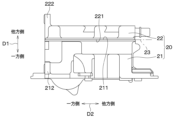
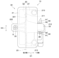
- FIG. 2 is a top view of the flow path forming device according to the first embodiment.
- FIG. 2 is a side view of the flow path forming device according to the first embodiment.
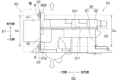
- FIG. 2 is a top view of the flow path forming device according to the first embodiment in a state before a valve is attached.
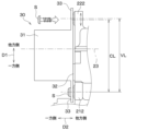
- FIG. 2 is a side view of the flow path forming device according to the first embodiment in a state before a valve is attached.
- 5A to 5C are schematic diagrams showing a method of attaching a valve and a casing according to the first embodiment.
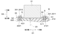
- FIG. 6 is an enlarged view of a portion VI in FIG. 5 .
- 11 is a diagram for explaining a valve hole distance and a case hole distance.
- FIG. FIG. 8 is an enlarged view of a portion VIII of FIG.
- FIG. 13 is a diagram showing a comparative example in which the valve is not attached to the casing across the joint surface.
- 13A and 13B are schematic diagrams showing a method of attaching a valve and a casing according to a second embodiment.
- FIG. 13 is a side view of a flow path forming device according to a third embodiment.
- 13A and 13B are diagrams for explaining sizes of a claw portion and a fitting portion.
- the flow path forming device 10 of the present disclosure is configured to be applicable to a fluid control system mounted on, for example, an electric vehicle, which is a vehicle.
- the fluid control system appropriately distributes heat generated in a refrigeration cycle and heat generated in various heat generating devices to various devices that require heat via a fluid that is a heat transport medium.
- the flow path forming device 10 is used to guide the fluid to various devices that require heat.
- the fluid that flows through the flow path forming device 10 is cooling water.
- the cooling water may be, for example, an antifreeze, but may also be a liquid containing water other than antifreeze.
- the flow path forming device 10 includes a casing 20 and a valve 30.
- the casing 20 is hollow and is a manifold that forms a flow path through which a fluid flows.
- the casing 20 is formed, for example, by resin molding.
- a flow path (not shown) is formed inside the casing 20, and it is possible to introduce a fluid from the flow path inside the casing 20 to the valve 30 or to lead the fluid from the valve 30 to the flow path inside the casing 20.
- the casing 20 has a first case part 21 and a second case part 22, which are assembled in a predetermined assembly direction.
- the valve 30 is assembled to a predetermined position in a direction different from the direction in which the first case part 21 and the second case part 22 are assembled to the casing 20.
- the flow path forming device 10 of this embodiment is configured to include the first case part 21, the second case part 22, and the valve 30.
- FIG. 2 in order to make it easier to understand the positional relationship between the first case part 21, the second case part 22, and the valve 30, the parts of the first case part 21 and the second case part 22 that are positioned on the back side of the valve 30 are shown with dashed lines.
- the first case part 21 corresponds to the first part
- the second case part 22 corresponds to the second part
- the valve 30 corresponds to the third part.
- the first case part 21 is hollow and has a bottom, and is open on the side opposite the bottom. As shown in Figures 1 to 4, the first case part 21 has a first joining surface 211 that joins with the second case part 22, a first case attachment part 212 where the valve 30 is attached, and three flow path insertion parts 213 into which the flow path parts 32 of the valve 30, which will be described later, are inserted.
- the second case part 22 is hollow and has a bottom, and is open on the side opposite the bottom.
- the second case part 22 has a second joining surface 221 that joins with the first case part 21, and a second case attachment part 222 where the valve 30 is attached.
- the first joint surface 211 is formed in a flat shape and is formed on the opening side opposite the bottom side.
- the second joint surface 221 is formed in a flat shape and is formed on the opening side opposite the bottom side.
- the casing 20 is assembled by joining the first joint surface 211 and the second joint surface 221, which are the opening sides of the first case part 21 and the second case part 22, respectively.
- the surface showing the boundary between the first case part 21 and the second case part 22 in the state where the first joint surface 211 and the second joint surface 221 are joined is referred to as the joint surface 23.
- the casing 20 has the joint surface 23 formed by joining the first joint surface 211 and the second joint surface 221. Then, the casing 20 is assembled by joining the first joint surface 211 and the second joint surface 221, so that the flow path formed inside is sealed. In other words, the first case part 21 and the second case part 22 form a flow path through which a fluid flows.
- the first joint surface 211 and the second joint surface 221 can be joined by, for example, welding, adhesion, or the like.
- the direction in which the first case part 21 and the second case part 22 are assembled is referred to as the first direction D1
- the direction perpendicular to the first direction D1 is referred to as the second direction D2.
- the first direction D1 is a direction that intersects with the joint surface 23, and more specifically, is a direction perpendicular to the joint surface 23.
- the first direction D1 corresponds to the surface perpendicular direction.
- the direction perpendicular to both the first direction D1 and the second direction D2 is referred to as the third direction D3.
- the flow path forming device 10 is attached to a vehicle so that the third direction D3 is the vertical direction, i.e., the top-to-bottom direction.
- the position of the flow path forming device 10 is just an example.
- the position of the flow path forming device 10 when mounted on a vehicle is not limited to those shown in Figures 1 and 2, etc.
- the first case mounting portion 212 is provided on the first case part 21 so as to protrude to one side in the first direction D1. As shown in FIG. 5, the first case mounting portion 212 is formed with a first case hole 2121 into which a screw S, which is a mounting member for mounting the valve 30 to the first case part 21, is inserted. A first nut N1 is inserted into the first case hole 2121 and fastened to the screw S. The first nut N1 is formed with a first screw hole N11 having a thread groove formed on its inner periphery into which the screw S is fastened.
- One of the three flow path insertion sections 213 is a fluid inlet port that introduces fluid into a flow path formed inside the casing 20, and the remaining two are fluid outlet ports that discharge fluid from the flow path formed inside the casing 20 to the outside of the casing 20.
- the three flow path insertion sections 213 have circular insertion ports so that the flow path section 32 of the valve 30 can be inserted.
- the flow path section 32 is inserted into the three flow path insertion sections 213 to connect the valve 30.
- the second case mounting portion 222 is provided on the second case part 22 so as to protrude to the other side in the first direction D1.
- the second case mounting portion 222 is provided at a position that is plane-symmetrical with respect to the first case mounting portion 212 of the first case part 21, with the joint surface 23 being the plane of symmetry.
- the second case mounting portion 222 is formed with a second case hole 2221 into which a screw S for mounting the valve 30 to the second case part 22 is inserted.
- a second nut N2 that is fastened to the screw S is inserted into the second case hole 2221.
- the second nut N2 is formed with a second screw hole N21 in which a screw groove into which the screw S is fastened is formed on the inner periphery.
- the first case hole 2121, the first screw hole N11, the second case hole 2221 and the second screw hole N21 each have an axis in a second direction D2 that intersects with the first direction D1.
- the valve 30 is fastened to the first case part 21 and the second case part 22 by screwing the screw S into the first nut N1 and the second nut N2, respectively.
- the valve 30 forms a flow path together with the casing 20 and switches the flow path of the fluid flowing through the fluid control system.
- the valve 30 may be configured, for example, as a multi-way valve having multiple fluid inlets (not shown) and multiple fluid outlets (not shown).
- the valve 30 has a valve body 31, three cylindrical flow path sections 32 protruding from the valve body 31, and two valve mounting sections 33 for mounting the valve 30 to the casing 20.
- the valve body 31 is the outer shell of the valve 30 and is formed into a hollow shape.
- the valve body 31 has a flow path inside and houses a valve body (not shown) that switches the flow path inside the valve body 31.
- valve 30 forms a flow path together with the casing 20 by inserting each of the three flow path sections 32 into the flow path insertion section 213 of the first case section 21 and connecting the flow path within the valve body 31 to the flow path within the casing 20.
- the valve mounting portion 33 is a portion where the screw S for mounting the valve 30 to the casing 20 is attached, and is formed in a rib shape that protrudes from the valve body 31 to one side and the other side in the first direction D1. As shown in FIG. 5, the valve mounting portion 33 is formed with a valve hole 331 into which the screw S is inserted.
- the valve hole 331 formed in the valve mounting portion 33 formed on one side of the first direction D1 is referred to as the first valve hole 3311
- the valve mounting portion 33 formed on the other side of the first direction D1 is referred to as the second valve hole 3312.
- the first valve hole 3311 and the second valve hole 3312 each have an axis in the second direction D2, which is a direction intersecting the first direction D1.
- the first valve hole 3311 and the second valve hole 3312 correspond to the third screw hole.
- the first valve hole 3311 is formed at a position overlapping the first case hole 2121 of the first case part 21 in the second direction D2.
- the second valve hole 3312 is formed at a position overlapping the second case hole 2221 of the second case part 22 in the second direction D2.
- the first valve hole 3311 is formed so that its axis overlaps with the axis of the first screw hole N11 of the first nut N1 inserted into the first case hole 2121.
- the second valve hole 3312 is formed so that its axis overlaps with the axis of the second screw hole N21 of the second nut N2 inserted into the second case hole 2221.
- the screw S inserted into the first case hole 2121 is inserted into the first valve hole 3311.
- the screw S inserted into the second case hole 2221 is inserted into the second valve hole 3312.
- the valve 30 is attached to the first case part 21 and the second case part 22 on one side of the casing 20 in the second direction D2.
- the valve 30 is fixed to the casing 20 by a screw S across the first case part 21 and the second case part 22 on one side of the casing 20 in the second direction D2.
- the valve 30 is fixed to the casing 20 across the joint surface 23 formed by joining the first joint surface 211 of the first case part 21 and the second joint surface 221 of the second case part 22.
- the flow path section 32 is inserted into the flow path insertion section 213, and the valve 30 is attached to the casing 20.
- an O-ring 40 which is a sealing member that suppresses leakage of fluid, is provided between the outer periphery of the flow path section 32 and the inner periphery of the flow path insertion section 213.
- the O-ring 40 is disposed in a compressed and elastically deformed state between the outer periphery of the flow path section 32 and the inner periphery of the flow path insertion section 213.
- the first valve diameter VL1 which is the inner diameter of the first valve hole 3311
- the first nut diameter NL1 which is the inner diameter of the first screw hole N11 of the first nut N1.
- the inner diameter of the second valve hole 3312 is formed to be larger by a predetermined size than the inner diameter of the second screw hole N21 of the second nut N2. The reason why the first valve diameter VL1 is formed to be larger than the first nut diameter NL1 and the inner diameter of the second valve hole 3312 is formed to be larger than the inner diameter of the second screw hole N21 in this way will be explained with reference to FIGS. 7 and 8.
- the distance between the center of the first screw hole N11 in the first case part 21 and the center of the second screw hole N21 in the second case part 22 may deviate from the preset design value.
- the positions of the first screw hole N11 and the second screw hole N21 may deviate from the preset design positions.
- the distance between the center of the first screw hole N11 and the center of the second screw hole N21 is referred to as the case hole distance CL.
- Causes of deviation of the case hole distance CL from the design value include, for example, errors due to design errors such as the flatness and planarity of the first joint surface 211 and the second joint surface 221, and assembly errors that occur during manufacturing.
- Causes of deviation of the first screw hole N11 and the second screw hole N21 from the design value include, for example, errors due to design errors of the first case mounting portion 212 and the second case mounting portion 222, and processing errors that occur when drilling the first screw hole N11 and the second screw hole N21.
- the first joint surface 211 and the second joint surface 221 are joined by welding, there is a risk of variation in the amount of melting when the first joint surface 211 and the second joint surface 221 are melted and welded.
- This variation in the amount of melting may cause the case hole distance CL, the first screw hole N11, and the second screw hole N21 to deviate from the design value.
- the deviation in the case hole distance CL and the positional deviation of the first screw hole N11 and the second screw hole N21 are caused by an error in the joint surface 23 formed by the first joint surface 211 and the second joint surface 221.
- the positions of the first valve hole 3311 and the second valve hole 3312 of the valve 30 are set so that the axis of the first valve hole 3311 overlaps with the axis of the first screw hole N11, and the axis of the second valve hole 3312 overlaps with the axis of the second screw hole N21.
- the valve hole distance VL which is the distance between the center of the first valve hole 3311 and the center of the second valve hole 3312, is set to be equal to the design value of the case hole distance CL.
- valve 30 is fixed to the first case part 21 and the second case part 22 by screwing in a state in which the axial centers of the first valve hole 3311 and the first screw hole N11, or the axial centers of the second valve hole 3312 and the second screw hole N21 do not overlap.
- a load is generated on the joint surface 23, and the load generated on this joint surface 23 is not limited to the first direction D1, but may be generated in any direction intersecting the first direction D1, for example, the third direction D3.
- Such a load can cause the first bonding surface 211 and the second bonding surface 221 to separate, damaging the bonding surface 23.
- the first valve diameter VL1 of the first valve hole 3311 is formed larger than the first nut diameter NL1 of the first screw hole N11
- the inner diameter of the second valve hole 3312 is formed larger than the inner diameter of the second screw hole N21.
- the first valve diameter VL1 is formed larger than the first nut diameter NL1 of the first screw hole N11 by an amount corresponding to the expected error of the joint surface 23.
- the inner diameter of the second valve hole 3312 is formed larger than the inner diameter of the second screw hole N21 by an amount corresponding to the expected error of the joint surface 23.
- the screw S can be inserted at a position offset from the axis of the second valve hole 3312. This makes it possible to absorb the offset between the valve hole distance VL and the case hole distance CL by the inner diameter of the second valve hole 3312 based on the error of the joint surface 23. Therefore, when the valve 30 is fastened to the second case part 22 by the screw S, it is possible to avoid the occurrence of a load on the joint surface 23 that would separate the first case part 21 and the second case part 22.
- the first valve hole 3311 and the second valve hole 3312 function as an attachment adjustment part that adjusts the attachment position of the valve 30 attached to the first case part 21 and the second case part 22 in the first direction D1 and adjusts the attachment position in the third direction D3 that intersects with the first direction D1.
- the outer diameter SL of the head of the screw S is sufficiently larger than the inner diameter of the first valve hole 3311 and the inner diameter of the second valve hole 3312. This makes it impossible for the head of the screw S to be inserted into the first valve hole 3311 or the second valve hole 3312.
- the flow path portion 32 is inserted into the flow path insertion portion 213, and the valve 30 is attached to the casing 20. Therefore, for example, when the valve 30 is shifted to one side or the other in the first direction D1 with respect to the design value and fixed to the casing 20 by the screw S, the flow path portion 32 is inserted into the flow path insertion portion 213, shifted to one side or the other in the first direction D1 according to the shift of the valve 30.
- the O-ring 40 provided between the flow path portion 32 and the flow path insertion portion 213 elastically deforms biasedly to one side or the other side in the first direction D1. If the O-ring 40 is maintained in a biased elastically deformed state, it may deteriorate. Deterioration of the O-ring 40 causes a deterioration in the sealing performance between the flow path portion 32 and the flow path insertion portion 213, and causes fluid to leak from between the flow path portion 32 and the flow path insertion portion 213.
- the first valve hole 3311 and the second valve hole 3312 make it possible to adjust the mounting position of the valve 30 attached to the first case portion 21 and the second case portion 22 in the first direction D1.
- the mounting position of the valve 30 is less likely to deviate from the design position. This in turn makes it less likely for the O-ring 40 to be biased toward one side or the other in the first direction D1 and elastically deform. This makes it possible to suppress leakage of fluid from between the flow path portion 32 and the flow path insertion portion 213 due to deterioration of the O-ring 40.
- the flow path portion 32 when attaching the valve 30 to the casing 20, the flow path portion 32 can be inserted into the flow path insertion portion 213, and then the valve 30 can be fixed to the casing 20 with the screw S.
- the valve 30 can be attached to the casing 20 so that the attachment position of the valve 30 approaches the designed position due to the inner diameter of the first valve hole 3311 and the inner diameter of the second valve hole 3312.
- the O-ring 40 when attached, is less likely to become biased in the first direction D1 and in a direction intersecting the first direction D1.
- the flow path forming device 10 of this embodiment includes the first case part 21 and the second case part 22 that form a flow path through which a fluid flows, and the valve 30 attached to the first case part 21 and the second case part 22.
- the first case part 21 has a first joint surface 211 that joins with the second case part 22.
- the second case part 22 has a second joint surface 221 that joins with the first case part 21, and the second joint surface 221 is joined to the first joint surface 211 and is joined to the first case part 21.
- the valve 30 is attached to the first case part 21 and the second case part 22 across the joint surface 23 formed by joining the first joint surface 211 and the second joint surface 221.
- the valve 30, which is attached across the joint surface 23, can improve the strength of the joint surface 23 where the first case part 21 and the second case part 22 are joined, thereby improving the rigidity of the entire flow path forming device 10. Therefore, even if a load is generated against the joint surface 23 that separates the first case part 21 and the second case part 22, damage to the joint surface 23 can be suppressed.
- the valve 30 is configured not to straddle the joint surface 23 when attached to the casing 20 as shown in FIG. 9, the strength of the joint surface 23 cannot be improved by attaching the valve 30.
- the valve 30 is joined and fixed only to the first case portion 21 as shown in FIG. 9.
- the load due to the weight of the attached valve 30 itself and the load due to the weight of the fluid flowing between the casing 20 and the valve 30 are applied to the joint surface 23.
- other parts such as the reservoir tank 50 shown in FIG. 9, are further attached to the second case portion 22, the load due to the weight of these other parts is also applied to the joint surface 23.
- the flow path forming device 10 of this embodiment is attached to the electric vehicle so that the third direction D3 perpendicular to the first direction D1 is vertical.
- a load is applied to the joint surface 23 in the third direction D3, i.e., the vertical direction, due to vibrations caused when the electric vehicle is running.
- it is difficult to improve the strength of the joint surface 23.
- the flow path forming device 10 of this embodiment can improve the strength of the joint surface 23 against loads in the third direction D3 by using the valve 30 attached to the casing 20 across the joint surface 23.
- the part that is attached to the casing 20 across the joint surface 23 is the valve 30, but this is not limited to this.
- the part that is attached to the casing 20 across the joint surface 23 can be, for example, any of various parts that can be attached to the casing 20 among the components of the fluid control system to which the flow path forming device 10 is applied, such as an electric pump, a heat exchanger, or a reservoir tank 50.
- the valve 30 has a first valve hole 3311 and a second valve hole 3312 that adjust the mounting position in the first direction D1 and the third direction D3 that intersects with the first direction D1.
- the case hole distance CL may deviate from a preset design value due to errors in the joint surface 23, such as design errors and assembly errors.
- the positions of the first screw hole N11 and the second screw hole N21 may deviate from the preset design positions.
- the valve 30 is attached to the first case part 21 and the second case part 22 based on the design value of the case hole distance CL, there is a risk that a load that separates the first case part 21 and the second case part 22 will be generated on the joint surface 23.
- the flow path forming device 10 is configured to be able to adjust the mounting position of the valve 30 in the first direction D1 and the third direction D3 using the first valve hole 3311 and the second valve hole 3312. Therefore, even if the case hole distance CL, the position of the first screw hole N11, and the position of the second screw hole N21 deviate from the design values, the load on the joint surface 23 caused by this deviation can be suppressed. This makes it possible to suppress damage to the joint surface 23.
- the valve 30 is attached to the first case part 21 and the second case part 22 by a screw S, and has a valve hole 331 into which the screw S is inserted.
- the first case part 21 has a first nut N1 in which a first screw hole N11 is formed, into which the screw S inserted into the valve hole 331 is inserted and fastened.
- the second case part 22 has a second nut N2 in which a second screw hole N21 is formed, into which the screw S inserted into the valve hole 331 is inserted and fastened.
- the valve hole 331, the first screw hole N11, and the second screw hole N21 have axes in a direction along the first direction D1.
- the first valve hole 3311 has an inner diameter that is larger by a predetermined size than the inner diameter of the first screw hole N11.
- the second valve hole 3312 has an inner diameter that is larger by a predetermined size than the inner diameter of the second screw hole N21. The first valve hole 3311 and the second valve hole 3312 adjust the mounting position of the valve 30 in the first direction D1 and the third direction D3.
- the predetermined size is determined based on the error of the bonding surface 23 formed by bonding the first bonding surface 211 and the second bonding surface 221.
- the sizes of the first valve hole 3311 and the second valve hole 3312 are determined based on errors in the joint surface 23, such as design errors and assembly errors of the first joint surface 211 and the second joint surface 221. Therefore, deviations in the case hole distance CL that correspond to errors in the joint surface 23 can be absorbed by the sizes of the first valve hole 3311 and the second valve hole 3312.
- the valve 30 has a flow path portion 32 that allows fluid to flow between the flow path formed by the first case portion 21 and the second case portion 22 and the valve 30.
- the valve 30 further has a flow path insert portion 213 that is inserted into the flow path portion 32, and an O-ring 40 that suppresses fluid leakage between the flow path portion 32 and the flow path insert portion 213.
- the valve 30 is attached to the first case portion 21 by inserting the flow path portion 32 into the flow path insert portion 213.
- the flow path forming device 10 of this embodiment is configured to be able to adjust the attachment position of the valve 30 in the first direction D1. Therefore, even if the case hole distance CL deviates from the design value, the attachment position of the valve 30 is less likely to deviate from the design position, and the O-ring 40 provided between the flow path portion 32 and the flow path insertion portion 213 is less likely to be biased and elastically deformed in the first direction D1 and in a direction intersecting the first direction D1.
- the flow path forming device 10 is applied to an electric vehicle, which is a vehicle.
- the fluid is cooling water.
- the load due to the weight of the cooling water flowing inside the casing 20 and the valve 30 is applied to the joint surface 23.
- the load on the joint surface 23 is likely to be greater than when the fluid is a gas. Therefore, in a flow path forming device 10 through which cooling water flows, it is more preferable to configure the valve 30 to be attached to the first case portion 21 and the second case portion 22 across the joint surface 23.
- the inner diameter of the first valve hole 3311 may be formed to be approximately equal to the inner diameter of the first screw hole N11.
- the inner diameter of the second valve hole 3312 may be formed to be approximately equal to the inner diameter of the second screw hole N21.
- the inner diameter of the first valve hole 3311 may be larger than the inner diameter of the first screw hole N11 by a predetermined size, and the inner diameter of the second valve hole 3312 may be formed to be approximately equal to the inner diameter of the second screw hole N21.
- the inner diameter of the first valve hole 3311 may be formed to be approximately equal to the inner diameter of the first screw hole N11, and the inner diameter of the second valve hole 3312 may be formed to be larger than the inner diameter of the second screw hole N21 by a predetermined size.
- a second embodiment will be described with reference to Fig. 10.
- a part of the structure for attaching the valve 30 to the first case portion 21 and the second case portion 22 is different from that of the first embodiment.
- the rest of the second embodiment is the same as the first embodiment. Therefore, in this embodiment, the parts that are different from the first embodiment will be mainly described, and the description of the parts that are the same as the first embodiment may be omitted.
- the flow path forming device 10 of this embodiment has a bush 70 and a collar 80 provided around the screw S.
- the bush 70 is an elastic part made of an elastic material such as resin, and is configured to be elastically deformable by a force applied from the outside.
- the bush 70 has a hollow cylindrical shape and has an elastic part hole 71 into which the screw S is inserted.
- the elastic part hole 71 has an axis in a second direction D2 that is a direction intersecting the first direction D1.
- the bush 70 also has a recess 72 at approximately the center of the outer periphery in the second direction D2 for fitting the bush 70 into the first valve hole 3311 of the valve attachment part 33.
- the recess 72 is formed by recessing the outer periphery of the bush 70 inward.
- the recess 72 of the bushing 70 is fitted into the first valve hole 3311.
- the elastically deformable bushing 70 is positioned between the inner periphery of the first valve hole 3311 and the outer periphery of the screw S.
- the bushing 70 is also positioned between one side of the bushing 70 in the second direction D2 and the screw S.
- the bushing 70 is then positioned between the other side of the bushing 70 in the second direction D2 and the first case mounting portion 212.
- the valve 30 of this embodiment is attached to the first case part 21 and the second case part 22 by a screw S inserted into the elastic part hole 71.
- the collar 80 is made of, for example, a material such as a metal that has greater rigidity than the bush 70.
- the collar 80 has a cylindrical tube portion 81 and an annular portion 82 that protrudes from one end of the tube portion 81 in the second direction D2 in a direction that expands radially from the axis of the tube portion 81 and is formed in a ring shape.
- the cylindrical portion 81 has an inner diameter that is slightly larger than the outer diameter of the screw S, and is configured so that the screw S can be inserted inside.
- the cylindrical portion 81 also has an outer diameter that is approximately the same as the inner diameter of the bush 70, and is configured so that it can be inserted inside the bush 70.
- the size of the cylindrical portion 81 in the second direction D2 is smaller than the size of the bush 70 in the second direction D2 when it is not elastically deformed.
- the annular portion 82 has a flat annular plate shape with an opening in the center, and is formed so that the plate surface is perpendicular to the second direction D2. In addition, the opening of the annular portion 82 is connected to the internal space of the tubular portion 81.
- the collar 80 has a cylindrical portion 81 inserted inside the bush 70, and an annular portion 82 disposed between the bush 70 and the screw S in the second direction D2.
- the flow path forming device 10 of this embodiment has a bush 70 that is made of an elastic material and has an elastic hole 71 into which a screw S is inserted.
- the elastic hole 71 has an axis in the second direction D2 that is perpendicular to the first direction D1.
- the valve 30 is attached to the first case part 21 and the second case part 22 by the screw S that is inserted into the elastic hole 71.
- the bush 70 elastically deforms in the first direction D1 and the third direction D3 in accordance with these deviations. This allows the bush 70 to absorb deviations in the first direction D1 and the third direction D3 from the design values of the case hole distance CL, the first screw hole N11, and the second screw hole N21.
- the positions at which the first joint surface 211 and the second joint surface 221 are joined to each other may shift in the second direction D2.
- the joint position of the first joint surface 211 relative to the second joint surface 221 may shift to one side in the second direction D2 with respect to the designed position.
- Such a positional shift of the first joint surface 211 and the second joint surface 221 in the second direction D2 is caused by an error in the joint surface 23 formed by the first joint surface 211 and the second joint surface 221.
- the bush 70 elastically deforms in the second direction D2 in accordance with this misalignment. This allows the bush 70 to absorb any misalignment in the second direction D2 from the design values of the first joint surface 211 and the second joint surface 221.
- cooling water flows inside the casing 20, and even if the casing 20 expands due to the heat of the cooling water flowing through the flow path inside the casing 20, the amount of expansion can be absorbed by the elastic deformation of the bushing 70. Therefore, even if a load caused by the expansion of the casing 20 occurs on the joint surface 23, the load on the joint surface 23 caused by the expansion of the casing 20 can be suppressed. This makes it possible to suppress damage to the joint surface 23.
- the collar 80 is made of a material having greater rigidity than the bush 70 and has a tubular portion 81 and an annular portion 82.
- the collar 80 has the tubular portion 81 inserted inside the bush 70, and the annular portion 82 disposed between the bush 70 and the screw S in the second direction D2.
- the collar 80 can limit the elastic deformation of the bushing 70 in the second direction D2.
- the collar 80 functions as a deformation limiting portion that limits the elastic deformation of the bushing 70 in a direction intersecting the first direction D1.
- the flow path forming device 10 of this embodiment has two snap fits 90 for attaching the valve 30 to the first case portion 21.
- the snap fits 90 have a claw portion 91 and a receiving portion 92 into which the claw portion 91 fits.
- the two snap fits 90 are provided on both sides of the valve attachment portion 33 in the third direction D3. This pair of snap fits 90 fix the valve 30 to the first case portion 21 by engaging the claw portions 91 with the receiving portions 92.
- the snap fit 90 has a claw portion 91 provided on the valve 30 and a receiving portion 92 provided on the first case portion 21.
- the snap fit 90 may also have a configuration in which the claw portion 91 is provided on the first case portion 21 and the receiving portion 92 is provided on the valve 30.
- the valve 30 and the second case portion 22 are attached by the screw S described in the first embodiment.
- the claw portions 91 are provided on the side surfaces of the valve mounting portion 33 on one side in the first direction D1, on both sides in the third direction D3.
- the claw portions 91 provided on the side surface of the valve mounting portion 33 on one side in the third direction D3 are formed to protrude toward one side in the third direction D3.
- the claw portions 91 provided on the side surface of the valve mounting portion 33 on the other side in the third direction D3 are formed to protrude toward the other side in the third direction D3.
- These claw portions 91 are formed in a triangular plate shape that decreases in size in the third direction D3 from one side to the other side in the second direction D2.
- the engagement portions 92 are formed in the first case mounting portion 212 at positions that overlap the claw portions 91 in the second direction D2, provided on one side and the other side of the valve mounting portion 33 in the third direction D3. As shown in FIG. 12, the engagement portions 92 are formed in a thin rectangular shape that protrudes toward one side in the second direction D2. The engagement portions 92 also have an engagement portion 921 into which the claw portions 91 are fitted. The engagement portion 921 is formed to penetrate in the third direction D3, and is formed in a rectangular shape when viewed from a direction along the third direction D3. The engagement portion 921 is sized to allow the claw portions 91 to be fitted therein.
- the engagement portion 921 is formed such that the size in the first direction D1 is smaller than the size of the claw portions 91 in the first direction D1, and the size in the second direction D2 is smaller than the size of the claw portions 91 in the second direction D2.
- the fitting portion 921 may be formed to have a trapezoidal shape when viewed from a direction along the third direction D3.
- the size of the claw portion 91 in the first direction D1 is the first claw length L1
- the size of the claw portion 91 in the second direction D2 is the second claw length L2
- the size of the fitting portion 921 in the first direction D1 is the first fitting length L3
- the size of the fitting portion 921 in the second direction D2 is the second fitting length L4.
- the first fitting length L3 is formed larger than the first claw length L1 by an amount corresponding to an expected error of the joint surface 23.
- the second fitting length L4 is formed larger than the second claw length L2 by an amount corresponding to an expected error of the joint surface 23.
- the second fitting length L4 is formed to be greater than the second claw length L2. Therefore, the position of the valve 30 in the second direction D2 can be adjusted by the fitting portion 921.
- valve 30 is attached to the first case part 21 by the snap fit 90 and attached to the second case part 22 by the screw S, but the present invention is not limited to this.
- the valve 30 may be attached to the first case part 21 and the second case part 22 by the snap fit 90.
- the bonding surface 23 is formed by bonding the first bonding surface 211 and the second bonding surface 221, which are formed in a planar shape, but this is not limited to the above.
- the bonding surface 23 may be formed by fitting and bonding the first bonding surface 211 and the second bonding surface 221, one of which is formed in a convex shape and the other of which is formed in a concave shape.
- the flow path forming device 10 is configured to be adjustable in the mounting position of the valve 30 in the first direction D1, but this is not limited thereto.
- the flow path forming device 10 may be configured in such a way that the mounting position of the valve 30 in the first direction D1 is not adjustable.
- the inner diameter of the first valve hole 3311 is larger than the inner diameter of the first screw hole N11 by the amount of error in the joint surface 23.
- An example has been described in which the inner diameter of the second valve hole 3312 is larger than the inner diameter of the second screw hole N21 by the amount of error in the joint surface 23.
- the first fitting length L3 is larger than the first claw length L1 by the amount of error in the joint surface 23, and the second fitting length L4 is larger than the second claw length L2 by the amount of error in the joint surface 23.
- this is not limiting.
- the inner diameter of the first valve hole 3311 may be larger than the inner diameter of the first screw hole N11 by a preset amount, regardless of the error of the joining surface 23.
- the inner diameter of the second valve hole 3312 may be larger than the inner diameter of the second screw hole N21 by a preset amount, regardless of the error of the joining surface 23.
- the first fitting length L3 may be larger than the first claw length L1 by a preset amount, regardless of the error of the joining surface 23.
- the second fitting length L4 may be larger than the second claw length L2 by a preset amount, regardless of the error of the joining surface 23.
- the fluid flowing through the flow passage of the flow passage forming device 10 is cooling water, but this is not limited to this.
- the fluid flowing through the flow passage of the flow passage forming device 10 may be a fluid other than cooling water, such as gas or oil.
- the flow path forming device 10 is mounted on a vehicle, which is an electric vehicle, but the present invention is not limited to this.
- the flow path forming device 10 may be applied to vehicles powered by an internal combustion engine, fluid control systems used in factories and homes, etc.
- a flow path forming device through which a fluid flows Three or more components (21, 22, 30),
- the three or more components include a first part (21) and a second part (22) that form a flow path through which the fluid flows, and a third part (30) that is attached to the first part and the second part,
- the first part has a first joining surface (211) that joins with the second part
- the second part has a second joining surface (221) that joins with the first joining surface
- the second joining surface is joined to the first joining surface and joined to the first part
- the third component is a flow path forming device that is attached to the first component and the second component across the joining surface.
- the flow path forming device described in the first aspect is provided with an attachment adjustment unit (N11, N21, 331, 70, 90) that adjusts at least one of the attachment positions of the third part in the surface orthogonal direction and the attachment position in a direction intersecting the surface orthogonal direction when the direction perpendicular to the joining surface is defined as the surface orthogonal direction.
- an attachment adjustment unit N11, N21, 331, 70, 90
- the third part is attached to the first part and the second part by a screw (S), and has a third screw hole (331) into which the screw is inserted;
- the first part has a first screw hole (N11) into which the screw to be inserted into the third screw hole is inserted and fastened,
- the second part has a second screw hole (N21) into which the screw to be inserted into the third screw hole is inserted and fastened, the first screw hole, the second screw hole, and the third screw hole have axes that intersect with a direction perpendicular to the surface,
- the mounting adjustment portion is configured such that the inner diameter of the third screw hole is formed to be larger than the inner diameter of at least one of the inner diameters of the first screw hole and the second screw hole by a predetermined size.
- the third part can be attached to the first part and the second part by a snap fit (90) having a claw part (91) and a receiving part (92) having a hollow fitting part (921) into which the claw part is fitted,
- the mounting adjustment portion has at least one of a shape in which the size of the fitting portion in the direction perpendicular to the surface is larger than the size of the claw portion in the direction perpendicular to the surface by a predetermined size, and a shape in which the size of the fitting portion in a predetermined direction intersecting the direction perpendicular to the surface is larger than the size of the claw portion in the predetermined direction by a predetermined size.
- the flow path forming device according to the third or fourth aspect, wherein the predetermined size is determined based on an error in the joining surface formed by joining the first joining surface and the second joining surface.
- the third part is attached to the first part and the second part by a screw (S);
- the mounting adjustment portion has an elastic portion (70) that is made of an elastic material and has an elastic portion hole (71) into which the screw is inserted,
- the elastic portion hole has an axis in a direction intersecting with the plane-orthogonal direction,
- the flow path forming device according to a second aspect, wherein the third part is attached to the first part and the second part by the screw inserted into the elastic part hole.
- the three or more components include a flow path portion (32) that allows the fluid to flow between the flow path formed by the first part and the second part and the third part, a flow path insert portion (213) into which the flow path portion is inserted, and a seal member (40) that suppresses leakage of the fluid between the flow path portion and the flow path insert portion,
- the flow path forming device according to any one of the second to seventh aspects, wherein the third component is attached to at least one of the first component and the second component by the flow path portion.
- the flow path forming device is applied to a vehicle, The flow path forming device according to any one of the first to ninth aspects, wherein the fluid is cooling water.
Landscapes
- Engineering & Computer Science (AREA)
- General Engineering & Computer Science (AREA)
- Mechanical Engineering (AREA)
- Chemical & Material Sciences (AREA)
- Combustion & Propulsion (AREA)
- Valve Housings (AREA)
Priority Applications (3)
| Application Number | Priority Date | Filing Date | Title |
|---|---|---|---|
| CN202480024061.3A CN120898094A (zh) | 2023-04-07 | 2024-03-08 | 流路形成装置 |
| DE112024001635.9T DE112024001635T5 (de) | 2023-04-07 | 2024-03-08 | Strömungspfadausbildungsvorrichtung |
| US19/348,318 US20260029062A1 (en) | 2023-04-07 | 2025-10-02 | Flow path forming device |
Applications Claiming Priority (2)
| Application Number | Priority Date | Filing Date | Title |
|---|---|---|---|
| JP2023-062945 | 2023-04-07 | ||
| JP2023062945A JP2024149213A (ja) | 2023-04-07 | 2023-04-07 | 流路形成装置 |
Related Child Applications (1)
| Application Number | Title | Priority Date | Filing Date |
|---|---|---|---|
| US19/348,318 Continuation US20260029062A1 (en) | 2023-04-07 | 2025-10-02 | Flow path forming device |
Publications (1)
| Publication Number | Publication Date |
|---|---|
| WO2024209880A1 true WO2024209880A1 (ja) | 2024-10-10 |
Family
ID=92972014
Family Applications (1)
| Application Number | Title | Priority Date | Filing Date |
|---|---|---|---|
| PCT/JP2024/009134 Ceased WO2024209880A1 (ja) | 2023-04-07 | 2024-03-08 | 流路形成装置 |
Country Status (5)
| Country | Link |
|---|---|
| US (1) | US20260029062A1 (https=) |
| JP (1) | JP2024149213A (https=) |
| CN (1) | CN120898094A (https=) |
| DE (1) | DE112024001635T5 (https=) |
| WO (1) | WO2024209880A1 (https=) |
Citations (4)
| Publication number | Priority date | Publication date | Assignee | Title |
|---|---|---|---|---|
| JP2003049706A (ja) * | 2001-08-06 | 2003-02-21 | Honda Motor Co Ltd | 車両用エンジン |
| US20190063623A1 (en) * | 2017-08-24 | 2019-02-28 | Continental Automotive Systems, Inc. | Combination multi-port valve |
| JP2019148314A (ja) * | 2018-02-28 | 2019-09-05 | 株式会社ケーヒン | 流路切替バルブ |
| JP2021080969A (ja) * | 2019-11-15 | 2021-05-27 | 株式会社不二工機 | 流路切換弁 |
Family Cites Families (3)
| Publication number | Priority date | Publication date | Assignee | Title |
|---|---|---|---|---|
| WO2019230796A1 (ja) * | 2018-05-31 | 2019-12-05 | 株式会社デンソー | バルブ装置 |
| JP7397456B2 (ja) | 2021-10-22 | 2023-12-13 | 株式会社サンセイアールアンドディ | 遊技機 |
| CN115388193A (zh) | 2022-05-06 | 2022-11-25 | 浙江吉利控股集团有限公司 | 一种集成式阀芯及其多通阀、阀泵装置和车身热管理系统 |
-
2023
- 2023-04-07 JP JP2023062945A patent/JP2024149213A/ja active Pending
-
2024
- 2024-03-08 CN CN202480024061.3A patent/CN120898094A/zh active Pending
- 2024-03-08 DE DE112024001635.9T patent/DE112024001635T5/de active Pending
- 2024-03-08 WO PCT/JP2024/009134 patent/WO2024209880A1/ja not_active Ceased
-
2025
- 2025-10-02 US US19/348,318 patent/US20260029062A1/en active Pending
Patent Citations (4)
| Publication number | Priority date | Publication date | Assignee | Title |
|---|---|---|---|---|
| JP2003049706A (ja) * | 2001-08-06 | 2003-02-21 | Honda Motor Co Ltd | 車両用エンジン |
| US20190063623A1 (en) * | 2017-08-24 | 2019-02-28 | Continental Automotive Systems, Inc. | Combination multi-port valve |
| JP2019148314A (ja) * | 2018-02-28 | 2019-09-05 | 株式会社ケーヒン | 流路切替バルブ |
| JP2021080969A (ja) * | 2019-11-15 | 2021-05-27 | 株式会社不二工機 | 流路切換弁 |
Also Published As
| Publication number | Publication date |
|---|---|
| DE112024001635T5 (de) | 2026-03-12 |
| US20260029062A1 (en) | 2026-01-29 |
| CN120898094A (zh) | 2025-11-04 |
| JP2024149213A (ja) | 2024-10-18 |
Similar Documents
| Publication | Publication Date | Title |
|---|---|---|
| US9417011B2 (en) | Heat exchanger with self-aligning fittings | |
| CN104975986A (zh) | 双壁燃料供应线路元件和用于所述元件的连接法兰 | |
| CN102759233B (zh) | 一种电子膨胀阀 | |
| KR20050104180A (ko) | 자동차용 증발기의 헤더 파이프 | |
| AU2005248347A1 (en) | Banjo fitting | |
| JP2014080187A (ja) | 燃料タンク接続アセンブリ | |
| WO2024209880A1 (ja) | 流路形成装置 | |
| EP4067715A1 (en) | Power element and expansion valve using same | |
| US6648375B1 (en) | Pilot insert seal for a tube fitting | |
| US11796067B2 (en) | Valve device | |
| US20160121710A1 (en) | Mounting structure for in-tank oil cooler and radiator | |
| JP2010270871A (ja) | 容器に対するパイプの接続構造 | |
| US20230127426A1 (en) | Connecting device for a sealed exchange of fluid between two components, connecting system and brake system | |
| CN119744333A (zh) | 带有密封结构的块式装配组件 | |
| CN218582370U (zh) | 一种切换阀 | |
| WO2017022399A1 (ja) | 熱交換器 | |
| CN113324121B (zh) | 法兰、阀组件及车辆制冷系统 | |
| CN114607847A (zh) | 管连接器和航空发动机 | |
| CZ2010296A3 (cs) | Prechodový adaptér pro pripojení dvou koaxiálne usporádaných trubek k txv ventilu v klimatizacním systému | |
| EP4726242A1 (en) | Connector device for connecting two spaced-apart conduits | |
| EP3546815B1 (en) | Pipe erroneous assembly preventing structure | |
| EP3071870B1 (en) | Tube fastener assembly and method for fastening a tube to tube fastener assembly | |
| KR20070102453A (ko) | 레듀싱커플링 및 이를 이용한 관연결구조 | |
| KR20100095679A (ko) | 차량 배관용 조인트 플랜지 및 그 제조방법 | |
| CN121230542A (zh) | 换热器及其接管组件 |
Legal Events
| Date | Code | Title | Description |
|---|---|---|---|
| 121 | Ep: the epo has been informed by wipo that ep was designated in this application |
Ref document number: 24784675 Country of ref document: EP Kind code of ref document: A1 |
|
| WWE | Wipo information: entry into national phase |
Ref document number: 202480024061.3 Country of ref document: CN |
|
| WWP | Wipo information: published in national office |
Ref document number: 202480024061.3 Country of ref document: CN |
|
| WWE | Wipo information: entry into national phase |
Ref document number: 112024001635 Country of ref document: DE |
|
| WWP | Wipo information: published in national office |
Ref document number: 112024001635 Country of ref document: DE |
|
| 122 | Ep: pct application non-entry in european phase |
Ref document number: 24784675 Country of ref document: EP Kind code of ref document: A1 |