WO2024209879A1 - 接続ユニット、アクセサリ及び電子機器 - Google Patents
接続ユニット、アクセサリ及び電子機器 Download PDFInfo
- Publication number
- WO2024209879A1 WO2024209879A1 PCT/JP2024/009101 JP2024009101W WO2024209879A1 WO 2024209879 A1 WO2024209879 A1 WO 2024209879A1 JP 2024009101 W JP2024009101 W JP 2024009101W WO 2024209879 A1 WO2024209879 A1 WO 2024209879A1
- Authority
- WO
- WIPO (PCT)
- Prior art keywords
- contact
- contacts
- accessory
- electronic device
- electrical contacts
- Prior art date
- Legal status (The legal status is an assumption and is not a legal conclusion. Google has not performed a legal analysis and makes no representation as to the accuracy of the status listed.)
- Ceased
Links
Images





Classifications
-
- G—PHYSICS
- G03—PHOTOGRAPHY; CINEMATOGRAPHY; ANALOGOUS TECHNIQUES USING WAVES OTHER THAN OPTICAL WAVES; ELECTROGRAPHY; HOLOGRAPHY
- G03B—APPARATUS OR ARRANGEMENTS FOR TAKING PHOTOGRAPHS OR FOR PROJECTING OR VIEWING THEM; APPARATUS OR ARRANGEMENTS EMPLOYING ANALOGOUS TECHNIQUES USING WAVES OTHER THAN OPTICAL WAVES; ACCESSORIES THEREFOR
- G03B13/00—Viewfinders; Focusing aids for cameras; Means for focusing for cameras; Autofocus systems for cameras
- G03B13/02—Viewfinders
-
- G—PHYSICS
- G03—PHOTOGRAPHY; CINEMATOGRAPHY; ANALOGOUS TECHNIQUES USING WAVES OTHER THAN OPTICAL WAVES; ELECTROGRAPHY; HOLOGRAPHY
- G03B—APPARATUS OR ARRANGEMENTS FOR TAKING PHOTOGRAPHS OR FOR PROJECTING OR VIEWING THEM; APPARATUS OR ARRANGEMENTS EMPLOYING ANALOGOUS TECHNIQUES USING WAVES OTHER THAN OPTICAL WAVES; ACCESSORIES THEREFOR
- G03B15/00—Special procedures for taking photographs; Apparatus therefor
- G03B15/02—Illuminating scene
- G03B15/03—Combinations of cameras with lighting apparatus; Flash units
- G03B15/05—Combinations of cameras with electronic flash apparatus; Electronic flash units
-
- G—PHYSICS
- G03—PHOTOGRAPHY; CINEMATOGRAPHY; ANALOGOUS TECHNIQUES USING WAVES OTHER THAN OPTICAL WAVES; ELECTROGRAPHY; HOLOGRAPHY
- G03B—APPARATUS OR ARRANGEMENTS FOR TAKING PHOTOGRAPHS OR FOR PROJECTING OR VIEWING THEM; APPARATUS OR ARRANGEMENTS EMPLOYING ANALOGOUS TECHNIQUES USING WAVES OTHER THAN OPTICAL WAVES; ACCESSORIES THEREFOR
- G03B17/00—Details of cameras or camera bodies; Accessories therefor
- G03B17/56—Accessories
-
- H—ELECTRICITY
- H04—ELECTRIC COMMUNICATION TECHNIQUE
- H04N—PICTORIAL COMMUNICATION, e.g. TELEVISION
- H04N23/00—Cameras or camera modules comprising electronic image sensors; Control thereof
- H04N23/50—Constructional details
-
- H—ELECTRICITY
- H04—ELECTRIC COMMUNICATION TECHNIQUE
- H04N—PICTORIAL COMMUNICATION, e.g. TELEVISION
- H04N23/00—Cameras or camera modules comprising electronic image sensors; Control thereof
- H04N23/56—Cameras or camera modules comprising electronic image sensors; Control thereof provided with illuminating means
Definitions
- connection units accessories and electronic devices.
- Patent Document 1 Accessory shoes to which camera accessories such as flash devices can be attached and detached are known (see, for example, Patent Document 1).
- the device described in Patent Document 1 does not give sufficient consideration to the appropriate placement of electrical contacts for data communication.
- connection unit is a connection unit provided in an accessory that is attached to an imaging device, and has a connection portion electrically connected to the imaging device, and a plurality of contacts provided on the connection portion and arranged in a line, and among the plurality of contacts, a first contact for receiving power from the imaging device is arranged next to an open drain contact or a contact with a backflow prevention function.
- the accessory includes the connection unit and a functional part that is electrically connected to the connection unit and has the function of the accessory.
- the electronic device is an electronic device having a connection part to which an accessory is attached and which is electrically connected to the accessory, the connection part having a plurality of contacts arranged in a line, and among the plurality of contacts, a contact used to supply power from the electronic device to the accessory is arranged next to an open drain contact or a contact with a backflow prevention function.
- the electronic device is an electronic device having a connection part to which an accessory is attached and which is electrically connected, the connection part having a flexible printed circuit board and a plurality of contacts arranged in a row, and among the plurality of contacts, a plurality of video signal contacts for transmitting a video data signal to a display accessory attached to the electronic device are arranged together at one end side of the row.
- the electronic device is an electronic device to which a first accessory is attached and to which the first accessory is attached via a second accessory, and has a plurality of first contacts and a plurality of second contacts, and when the first accessory is attached, the plurality of first contacts and the first accessory are electrically connected, and when the first accessory is attached via the second accessory, the second accessory and the electronic device are electrically connected using a part of the plurality of first contacts and a predetermined contact of the plurality of second contacts.
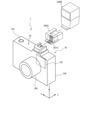
- FIG. 1 is a perspective view (part 1) showing an interchangeable lens camera as an electronic device according to an embodiment.
- FIG. 2 is a second perspective view showing a lens-interchangeable camera as an electronic device according to an embodiment.
- FIG. 3 is a diagram showing a case where the accessory is a flash device.
- FIG. 4 is a diagram showing how the intermediate adapter is attached to the camera body and then the flash device is attached to the intermediate adapter.
- FIG. 5 shows a state in which the flash device is attached to the camera body via an intermediate adapter.
- Figure 6(a) is a view of the shoe seat from the +Y direction
- Figure 6(b) is a view of the plug provided on the EVF unit from below (-Y side)
- Figure 6(c) is a view of the plug provided on the flash device from below (-Y side).
- Figure 7(a) is a diagram showing the intermediate adapter as viewed from below (-Y side)
- Figure 7(b) is a diagram showing the intermediate adapter and plug as viewed from the +X direction
- Figure 7(c) is a diagram showing the intermediate adapter as viewed from above (+Y side).
- FIG. 8 is a block diagram showing a schematic configuration of an accessory having a plug similar to that of a camera body and an EVF unit.
- FIG. 8 is a block diagram showing a schematic configuration of an accessory having a plug similar to that of a camera body and an EVF unit.
- FIG. 9 is a table showing the names and functions of the 26 electrical contacts provided on the shoe seat.
- FIG. 10 is a block diagram showing a schematic configuration of an accessory having a camera body and a plug similar to that of a flash device.
- FIG. 11 is a block diagram showing a schematic configuration when an intermediate adapter is interposed between a camera body and an accessory.
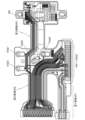
- FIG. 12 is a diagram showing an example of a flexible printed circuit board provided with wiring connected to electrical contacts provided on a shoe seat of a camera body (electronic viewfinderless camera).
- FIG. 13 is a diagram showing an example of a flexible printed circuit board provided with wiring connected to electrical contacts provided on a shoe seat of a camera body (a camera with an electronic viewfinder).
- FIGS. 1 and 2 are perspective views showing an interchangeable lens camera 1 as an electronic device according to one embodiment.
- the optical axis direction of an interchangeable lens 200 (described later) is the Z-axis direction
- the left-right direction of the camera body 100 is the X-axis direction
- the up-down direction of the camera body 100 is the Y-axis direction.
- Camera 1 comprises a camera body 100 and an interchangeable lens 200.
- a user of camera 1 can select any interchangeable lens 200 and attach it to the camera body 100 for use.
- a user of camera 1 can also select any accessory 300 and attach it to the camera body 100 for use. Note that camera 1 does not have to be a camera with interchangeable lenses.
- An interchangeable lens 200 is removably provided on the front surface (-Z surface) of the camera body 100.
- An image sensor 102 such as a CMOS (Complementary Metal-Oxide-Semiconductor) or CCD (Charge Coupled Device), is also provided inside the camera body 100.
- a release switch 103 is provided on the top surface (+Y surface) of the camera body 100.
- various buttons 104 are provided on the rear surface (+Z surface) of the camera body 100. A user can use the release switch 103, buttons 104, etc. to input shooting instructions, shooting condition setting instructions, etc. to the camera body 100.
- a rear monitor 105 is provided on the rear (+Z side) of the camera body 100.
- the rear monitor 105 is a display device that uses, for example, a liquid crystal display.
- the rear monitor 105 displays, for example, a live view of the subject image and a menu of shooting settings.
- the top surface (+Y side surface) of the camera body 100 is provided with an accessory shoe (hereinafter, shoe seat 106) for attaching the accessory 300.
- shoe seat 106 functions as a connection between the accessory 300 and the camera body 100, and the shoe seat 106 is provided with a retaining portion 106a for maintaining the accessory 300 in an attached state.
- the retaining portion 106a holds the plug 301 provided on the accessory 300 so that the accessory 300 does not come off the camera body 100 even if an external force is applied to the accessory 300.
- the accessory 300 is, for example, an EVF (electronic viewfinder) unit, a flash device, an LED light, a tally lamp, a microphone, a GNSS (Global Navigation Satellite System) receiver, an auxiliary imaging device, or a device that combines these.
- EVF electronic viewfinder
- flash device an LED light
- tally lamp a tally lamp
- microphone a microphone
- GNSS Global Navigation Satellite System
- auxiliary imaging device or a device that combines these.
- Figures 1 and 2 illustrate a case where the accessory 300 is an EVF unit 300A
- Figure 3 illustrates a case where the accessory 300 is a flash device 300B.
- the EVF unit 300A in Figure 1 is provided with a plug 301A
- the flash device 300B in Figure 3 is provided with a plug 301B.
- the accessory 300 also includes an intermediate adapter 300C that is placed between the flash device 300B, EVF unit 300A, etc. and the camera body 100 when the flash device 300B, EVF unit 300A, etc. are attached to the camera body 100 (see Figures 4 and 5).
- the intermediate adapter 300C has a built-in function as a wireless remote controller transmitter/receiver and a Genlock function, and is provided with a BNC terminal, a USB terminal, etc.
- FIG. 4 shows how an intermediate adapter 300C (second accessory) is attached to the camera body 100, and then a flash device 300B (first accessory) is attached to the intermediate adapter 300C.
- a plug 301C is provided on the intermediate adapter 300C.
- FIG. 5 shows the state in which the flash device 300B is attached to the camera body 100 via the intermediate adapter 300C.
- Figure 6(a) is a view of the shoe seat 106 as viewed from the +Y direction.
- the retaining portion 106a of the shoe seat 106 is shown in cross section.
- second contacts near the -Z end of the upper surface (+Y side surface) of the shoe seat 16, 22 or more (26 in Figure 6(a)) electrical contacts (second contacts) PB1, PB2, ... PB26 are provided in a row along the X-axis direction.
- four electrical contacts (first contacts) PSB1 to PSB4 are provided in the center of the upper surface (+Y side surface) of the shoe seat 16.
- Figure 6(b) shows the plug 301A provided in the EVF unit 300A as viewed from below (-Y side).
- connection portion 39A which is connected to shoe seat 109, and 26 electrical contacts PA1 to PA26 are arranged in a row in the X-axis direction on connection portion 39A.
- EVF unit 300A is attached to camera body 100, each of the 26 electrical contacts PA1 to PA26 on the underside of plug 301A comes into physical contact with each of the 26 electrical contacts PB1 to PB26 on the upper surface of shoe seat 106. This electrically connects each of the 26 electrical contacts PA1 to PA26 to each of the 26 electrical contacts PB1 to PB26.
- electrical contacts PA1 to PA26 have a crank-like shape bent at two points within plug 301A, as shown in gray in FIG. 1.
- the shape of the electrical contacts PA1 to PA26 is designed to avoid mechanical interference with the retaining portion 106a of the shoe seat 106.
- plug 301A of EVF unit 300A does not have electrical contacts that correspond to the four electrical contacts PSB1 to PSB4 provided on shoe seat 16. Therefore, even if EVF unit 300A is attached to camera body 100, the four electrical contacts PSB1 to PSB4 are not electrically connected to EVF unit 300A. In other words, EVF unit 300A does not input or output electrical signals to or from camera body 100 via the four electrical contacts PSB1 to PSB4.
- Figure 6(c) shows the plug 301B provided on the flash device 300B as viewed from below (-Y side).
- each of the four electrical contacts PSA1 to PSA4 are provided in the center of the bottom surface (the surface on the -Y side) of plug 301B.
- each of the four electrical contacts PSA1 to PSA4 provided on the bottom surface of plug 301A comes into physical contact with each of the four electrical contacts PSB1 to PSB4 (FIG. 6(a)) provided on the top surface of shoe seat 106. This electrically connects each of the four electrical contacts PSA1 to PSA4 to each of the four electrical contacts PSB1 to PSB4.
- plug 301B of flash device 300B does not have electrical contacts that correspond to the 26 electrical contacts PB1 to PB26 provided on shoe seat 16. Therefore, even if flash device 300B is attached to camera body 100, the 26 electrical contacts PB1 to PB26 are not electrically connected to flash device 300B. In other words, flash device 300B does not input or output electrical signals to or from camera body 100 via the 26 electrical contacts PB1 to PB26.
- Figure 7(a) shows the plug 301C of the intermediate adapter 300C as viewed from below (-Y side).
- Figure 7(b) shows the intermediate adapter 300C and plug 301C as viewed from the +X direction, with the intermediate adapter 300C shown by a two-dot chain line and the plug 301C shown by a solid line.
- Figure 7(c) shows the intermediate adapter 300C as viewed from above (+Y side).
- a connection portion 39C that connects to the shoe seat 109 is provided at the -Z end of the underside (-Y side) of the plug 301C, and 26 electrical contacts PC1 to PC26 are arranged in a row in the X-axis direction on the connection portion 39C.
- each of the 26 electrical contacts PC1 to PC26 on the underside of the intermediate adapter 300C comes into physical contact with each of the 26 electrical contacts PB1 to PB26 on the upper surface of the shoe seat 106. This electrically connects each of the 26 electrical contacts PC1 to PC26 to each of the 26 electrical contacts PB1 to PB26.
- three electrical contacts PSC1 to PSC3 are provided near the center of the underside of the plug 301C. As can be seen from Figures 7(a) to 7(c), these three electrical contacts PSC1 to PSC3 penetrate the plug 301C and the intermediate adapter 300C in the Y-axis direction and are exposed on the upper surface of the intermediate adapter 300C.
- each of the three electrical contacts PSC1 to PSC3 on the lower surface of the intermediate adapter 300C comes into physical contact with each of the three electrical contacts PSB1 to PSB3 (see Figure 6(a)) provided on the upper surface of the shoe seat 106. This electrically connects each of the three electrical contacts PSC1 to PSC3 to each of the three electrical contacts PSB1 to PSB3.
- the electrical contacts PC1 to PC26 like the electrical contacts PA1 to PA26, have a crank-like shape bent at two points as shown by the dashed lines in FIG. 7B.
- the shape of the electrical contacts PC1 to PC26 is designed to avoid mechanical interference with the retaining portion 106a of the shoe seat 106. Because the electrical contacts PC1 to PC26 have such a shape and parts of the electrical contacts PC1 to PC26 are present at the positions shown in the dashed circles in FIG. 7A, the electrical contact corresponding to the electrical contact PSB4 provided on the shoe seat 16 cannot be provided in a state that penetrates the intermediate adapter 300C and plug 301C in the Y-axis direction, unlike the electrical contacts PSC1 to PSC3.
- the electrical contact PSB4 in FIG. 6A is not electrically connected to the intermediate adapter 300C (plug 301C). In other words, the intermediate adapter 300C does not input or output electrical signals to or from the camera body 100 via the electrical contact PSB4.
- the upper surface (+Y side surface) of the intermediate adapter 300C has an electrical contact PSC4 in addition to the three electrical contacts PSC1 to PSC3. That is, the intermediate adapter 300C has electrical contacts that penetrate in the Y-axis direction and electrical contacts that do not.
- the electrical contact PSC4 does not penetrate the intermediate adapter 300C in the Y-axis direction, and is electrically connected to one of the 26 electrical contacts PC1 to PC26 in FIG. 7(a) (electrical contact PC13 in this embodiment) via a flexible printed circuit board (see the double-headed arrow in FIG. 7(b)).
- each of the four electrical contacts PSA1 to PSA4 (see FIG. 6(c)) provided on the underside of the flash device 300B comes into physical contact with each of the four electrical contacts PSC1 to PSC4 provided on the upper surface of the intermediate adapter 300C (see dashed circles PSA1 to PSA4 in FIG. 7(c)).
- This allows each of the four electrical contacts PSA1 to PSA4 to be electrically connected to each of the four electrical contacts PSC1 to PSC4 while avoiding mechanical interference with the retaining portion 106a of the shoe seat 106.
- FIG. 8 is a block diagram showing a schematic configuration of a camera body 100 and an accessory (referred to as accessory 300A) having a plug 301A similar to the EVF unit 300A.
- the camera body 100 includes a body control unit 110.
- the body control unit 110 includes a CPU (Central Processing Unit), RAM (Random-Access Memory), and ROM (Read-Only Memory), etc.
- CPU Central Processing Unit
- RAM Random-Access Memory
- ROM Read-Only Memory
- the 26 electrical contacts PB1 to PB26 provided on the shoe seat 106 are assigned functions as shown in FIG. 9.
- the electrical contacts PB2 to PB7 are contacts for transmitting video data signals to the accessory 300A.
- the electrical contacts PB9 to PB12 are contacts for transmitting control signals to the accessory 300A.
- the electrical contact PB13 is a contact for transmitting a strobe signal (a flash instruction signal to the flash device 300B).
- the electrical contacts PB14 and PB15 are contacts for supplying power to the accessory 300A.
- the voltages VDD and VBAT are respectively supplied to the electrical contacts PB14 and PB15 from the power supply circuit 130 connected to the battery 120 under the control of the body control unit 110.
- the electrical contacts PB16 to PB19 are contacts used for exchanging a release signal, an insertion/removal detection signal, a half-press signal, and a multifunction signal, respectively.
- the electrical contact PB19 is a terminal capable of receiving a plurality of types of signals from the accessories 300A and 300C.
- the form of the signal output from the electrical contact PB19 varies depending on the type and manufacturer of the accessories 300A and 300C, and the electrical contact PB19 can receive signals of various output forms by switching the pull-up on and off in the body control unit 110 inside the camera body 100.
- Receivable signals include, for example, a CMOS output signal and an open drain output signal.
- the body control unit 110 switches the internal pull-up on and off, so that the electrical contact PB19 receives a signal of the corresponding output form while the same accessory is attached.
- the electrical contacts PB24 to PB26 are contacts for transmitting an audio data signal to the accessory 300A.
- the electrical contacts PB1, PB8, and PB23 are grounded, and the electrical contacts PB20 to PB22 are unused terminals (spare terminals). The unused terminals are provided so that new functions of accessories and cameras can be supported by firmware updates, etc.
- the electrical contacts arranged in a row are arranged in order from one side to the other in the following order: video data signal terminal group PB2-PB7, control signal terminal group PB9-PB12, power supply terminal group PB14-PB15, free terminal group PB20-PB22, audio data signal group PB24-PB26, but the order of arrangement of each terminal group may be changed.
- terminals have the same purpose, the signals are often synchronized or connected to the same IC chip, so it is preferable in terms of wiring to arrange terminal groups with the same purpose consecutively in order. It is preferable to provide a GND (ground) terminal between each terminal group.
- three GND (ground) terminals, PB1, PB8, and PB23, are provided, but these can be omitted as appropriate.
- Accessory 300A comprises accessory control unit 310 and functional unit 320.
- Functional unit 320 is a component for performing the functions of accessory 300A. If accessory 300A is EVF unit 300A, functional unit 320 is a display device, and if accessory 300A is a GPS receiver, functional unit 320 is a GPS module.
- 26 electrical contacts PA1 to PA26 of accessory 300A are electrically connected to 26 electrical contacts PB1 to PB26 provided on shoe seat 106 of camera body 100. On the other hand, nothing is connected to the four electrical contacts PSB1 to PSB4.
- the accessory 300A of this embodiment has 26 electrical contacts, but electrical contacts that are not necessary for the accessory to function can be omitted as appropriate.
- terminals for audio data signals, empty terminals, and strobe signals can be omitted.
- terminals for video data signals, empty terminals, and strobe signals can be omitted.
- either the power-related electrical contact PB14 or the electrical contact PB15 can be omitted.
- FIG. 10 is a block diagram showing a schematic configuration of an accessory (referred to as accessory 300B) having a camera body 100 and a plug 301B similar to flash device 300B.
- accessory 300B has four electrical contacts PSA1 to PSA4 and a functional unit 330. If accessory 300B is a flash device, functional unit 330 is a light-emitting device.
- the four electrical contacts PSA1 to PSA4 of the accessory 300B are electrically connected to the four electrical contacts PSB1 to PSB4 provided on the shoe seat 106 of the camera body 100.
- nothing is connected to the 26 electrical contacts PB1 to PB26.
- FIG. 11 is a block diagram showing a schematic configuration when an intermediate adapter 300C is interposed between the camera body 100 and the accessory 300B.
- electrical contact PC13 which is one of the 26 electrical contacts PC1 to PC26, is electrically connected to electrical contact PCS4 via wiring provided on the flexible printed circuit board, and the remaining 25 electrical contacts PC1 to PC12 and PC14 to PC26 are connected to a functional unit 340 via wiring provided on the flexible printed circuit board.
- the functional unit 340 is, for example, a transmitting/receiving device for a wireless remote controller.
- the four electrical contacts PSA1 to PSA4 of the accessory 300B are electrically connected to the four electrical contacts PSC1 to PSC4 provided on the top surface of the intermediate adapter 300C.
- the intermediate adapter 300C By using the intermediate adapter 300C, it is possible to simultaneously use the functions of the intermediate adapter 300C (e.g., function as a wireless remote controller transmitting and receiving device) and the functions of the accessory 300B (e.g., function as a flash device). This makes it possible, for example, to control a flash device located away from the camera body 100 using wireless communication, and shoot with multiple lights by simultaneously emitting light from this flash device and the accessory 300B (flash device) attached to the camera body 100.
- the functions of the intermediate adapter 300C e.g., function as a wireless remote controller transmitting and receiving device
- the accessory 300B e.g., function as a flash device
- the number of electrical contacts arranged in a row is 26.
- the number of electrical contacts is, for example, 21 or 15, and in the case of 21 electrical contacts, the spacing (pitch) between the electrical contacts is approximately 0.45 mm.
- the range in which the electrical contacts can be arranged is determined by standards, so the spacing (pitch) between the electrical contacts is narrower than in the case of 21 electrical contacts, and is approximately 0.43 mm.
- an open drain contact or an electrical contact with a backflow prevention function is arranged on both sides of the electrical contact PB15 (VBAT_ACC).
- an open drain contact means a contact connected to the drain terminal of an FET, and a contact with a backflow prevention function means, for example, a contact to which a diode is connected, or a contact connected to a power source via a circuit for preventing backflow.
- an electrical contact PB16 (ACC_RLS) is arranged next to one side of the electrical contact PB15.
- the electrical contact PB16 (ACC_RLS) is an open drain contact.
- an electrical contact PB14 (VDD_ACC) is arranged next to the other side of the electrical contact PB15.
- the electrical contact PB14 (VDD_ACC) is a contact with a backflow prevention function.
- the electrical terminals on either side of the electrical contact PB15 there are two terminals for supplying voltage, PB14 (VDD_ACC) and PB15 (VBAT_ACC), and electrical contacts for preventing damage are arranged on either side of the electrical contact PB15, which is supplied with a higher voltage.
- the electrical contact PB14 supplies power to control the accessory 300 at a lower voltage than the electrical contact PB15.
- the electrical contact PB15 supplies power necessary for the accessory 300 to function, and depending on the function, it supplies high power and a variable voltage. Therefore, in this embodiment, it is possible to prevent the electrical terminals on either side of the electrical contact PB15 from being shorted out, which would cause significant damage.
- electrical contacts that can be placed on either side of electrical contact PB15 include, for example, ACC_WUP (half-press signal) (electrical contact PB18 in Figure 9).
- electrical contact PB18 (WUP terminal) and electrical contact PB16 (RLS terminal) are placed on either side of electrical contact PB17 (DET terminal), and are placed so that they are sandwiched between the pulled-up terminals.
- Both electrical contact PB18 (WUP terminal) and electrical contact PB16 (RLS terminal) are open-drain contacts.
- electrical contacts PB1 to PB26 electrical contact PB17 (DET terminal) and electrical contact PB15 (VBAT terminal) are terminals that particularly need to be protected from damage.
- the open drain contacts or contacts with backflow prevention function are the three electrical contacts PB14, PB16, and PB18, and the electrical contact PB17 (DET terminal) and the electrical contact PB15 (VBAT terminal) are arranged between these three terminals.
- the electrical contact PB18 (WUP terminal) and the electrical contact PB16 (RLS terminal) may be interchanged.
- the electrical contact PB13 is a contact (TTL) for transmitting a strobe signal.
- TTL contact for transmitting a strobe signal.
- This electrical contact PB13 is an electrical contact that is not used unless the flash device 300B is attached via the intermediate adapter 300C as shown in FIG.
- the circuit is designed so that the electrical contact PB13 functions when a signal (insertion/removal detection signal) that the intermediate adapter 300C has been attached to the camera body 100 is detected via the electrical contact PB17 (attachment detection contact). This makes it possible to prevent foreign matter, etc. from entering the electrical contact PB13 while it is not in use, causing the electrical contact PB13 to short out due to the foreign matter, etc.
- FPC 500 flexible printed circuit board
- This FPC 500 is an FPC used inside a camera body 100 that does not have an EVF (an electronic viewfinderless camera).
- the FPC 500 is provided with terminals PB1' to PB26' that are connected to the 26 electrical contacts PB1 to PB26 described above, and terminals PSB1' to PSB4' that are connected to the four electrical contacts PSB1 to PSB4.
- the FPC 500 in FIG. 12 has a first area AR1 in which wiring is provided that connects to electrical contacts PB2-PB7 for transmitting video data signals, a second area AR2 in which the other wiring is provided, and a third area AR3 in which terminals PSB1'-PSB4' for the four electrical contacts PSB1-PSB4 and wiring for driving the flash device are arranged.
- Terminals PB1'-PB26' and PSB1'-PSB4' are connected to various parts inside the camera body 100 via the wiring provided on the FPC 500.
- FIG. 13 shows an FPC 600 provided on the shoe seat 106 of a camera body 100 (a camera with an electronic viewfinder) that is already equipped with an EVF.
- a camera with an electronic viewfinder it is not necessary to assume that an accessory (such as the EVF unit 300A) that requires sending a video data signal will be attached to the camera body 100. Therefore, in the example of FIG. 13, wiring for electrical contacts PB2 to PB7 for sending a video data signal is not required. In this case, unnecessary wiring can be omitted, and the first area AR1 in FIG. 12 can be omitted, simplifying the configuration inside the camera body 100.
- the electrical contacts for transmitting video data signals in the shoe seat 106 are arranged together at one end of the row of 26 electrical contacts, so that unnecessary areas of the FPC 600 used in cameras with electronic viewfinders can be reduced. This allows costs to be reduced.
- the plug 301A (301C) provided on the accessory 300A (300C) attached to the camera body 100 has a connection portion 39A (39C) electrically connected to the shoe seat 106 of the camera body 100, and a plurality of electrical contacts PA1 to PA26 (PC1 to PC26) provided on the connection portion 39A (39C) and arranged in a row.
- the electrical contact (first contact) PA15 (PC15) for supplying power from the camera body 100 is arranged next to the open drain contact or the contact with a backflow prevention function.
- the camera body 100 of this embodiment has a shoe seat 106 electrically connected to the accessory 300, and the shoe seat 106 has electrical contacts PB1 to PB26 arranged in a row.
- the electrical contacts PB1 and PB2 the electrical contacts (PB14, PB16) adjacent to the power contact (electrical contact PB15) used to supply power from the camera body 100 to the accessory 300 are open drain contacts or contacts with a backflow prevention function. This makes it possible to prevent the electrical contacts PB14 and PB16 from shorting out and being damaged by foreign objects, etc.
- electrical contacts for preventing damage are arranged on both sides of electrical contact PB15, which is supplied with a higher voltage. This makes it possible to prevent the electrical terminals on either side of electrical contact PB15 from shorting out, which would increase the impact of damage.
- electrical contact PB18 (open drain contact) and electrical contact PB16 (open drain contact) are arranged on either side of electrical contact PB17 (DET terminal), and are arranged so that they are sandwiched between the pulled-up terminals. This makes it possible to efficiently arrange the electrical contacts while protecting them from damage.
- the shoe seat 106 has an FPC (500 or 600) and multiple electrical contacts PB1 to PB26 arranged in a row, and among the multiple electrical contacts PB1 to PB26, the multiple electrical contacts PB2 to PB7 for transmitting video data signals to the EVF unit 300A are arranged together at one end of the row.
- FPC 500 or 600
- PB1 to PB26 the multiple electrical contacts PB2 to PB7 for transmitting video data signals to the EVF unit 300A are arranged together at one end of the row.
- the camera body 100 to which the accessory 300B, such as a flash device, is attached and to which the accessory 300B is attached via the intermediate adapter 300C has four electrical contacts PSB1 to PSB4 and 26 electrical contacts PB1 to PB26.
- the electrical contacts PSA1 to PSA4 of the accessory 300B are connected to the four electrical contacts PSB1 to PSB4.
- the electrical contacts PSA1 to PSA4 of the accessory 300B are connected via the intermediate adapter 300C to the three electrical contacts PSB1 to PSB3 and to electrical contact PB13, which is one of the 26 electrical contacts PB1 to PB26.
- electrical contact PB13 which is one of the 26 electrical contacts PB1 to PB26, instead of electrical contact PSB4, it is possible to attach accessory 300B to camera body 100 via intermediate adapter 300C and use it, even in cases where electrical contact PSB4 cannot be used when intermediate adapter 300C is attached.
- electrical contact PB13 is set to function. This makes it possible to prevent foreign matter from entering while the intermediate adapter 300C is not attached, causing the electrical contact PB13 to short out and become damaged.
- the shoe seat 106 described in the above embodiment may also be provided in electronic devices other than cameras.
Landscapes
- Physics & Mathematics (AREA)
- General Physics & Mathematics (AREA)
- Engineering & Computer Science (AREA)
- Multimedia (AREA)
- Signal Processing (AREA)
- Accessories Of Cameras (AREA)
Priority Applications (2)
| Application Number | Priority Date | Filing Date | Title |
|---|---|---|---|
| JP2025512459A JPWO2024209879A1 (https=) | 2023-04-06 | 2024-03-08 | |
| CN202480021811.1A CN121014018A (zh) | 2023-04-06 | 2024-03-08 | 连接单元、附件以及电子设备 |
Applications Claiming Priority (2)
| Application Number | Priority Date | Filing Date | Title |
|---|---|---|---|
| JP2023062207 | 2023-04-06 | ||
| JP2023-062207 | 2023-04-06 |
Publications (1)
| Publication Number | Publication Date |
|---|---|
| WO2024209879A1 true WO2024209879A1 (ja) | 2024-10-10 |
Family
ID=92972000
Family Applications (1)
| Application Number | Title | Priority Date | Filing Date |
|---|---|---|---|
| PCT/JP2024/009101 Ceased WO2024209879A1 (ja) | 2023-04-06 | 2024-03-08 | 接続ユニット、アクセサリ及び電子機器 |
Country Status (3)
| Country | Link |
|---|---|
| JP (1) | JPWO2024209879A1 (https=) |
| CN (1) | CN121014018A (https=) |
| WO (1) | WO2024209879A1 (https=) |
Citations (4)
| Publication number | Priority date | Publication date | Assignee | Title |
|---|---|---|---|---|
| JP2004309834A (ja) * | 2003-04-08 | 2004-11-04 | Canon Inc | 像ブレ防止機能を有するカメラシステム |
| JP2018025738A (ja) * | 2015-10-30 | 2018-02-15 | キヤノン株式会社 | 電子機器 |
| JP2018084681A (ja) * | 2016-11-24 | 2018-05-31 | キヤノン株式会社 | アクセサリシュー装置、撮像装置、及びアクセサリ |
| JP2021167947A (ja) * | 2020-04-09 | 2021-10-21 | キヤノン株式会社 | 電子機器およびアクセサリ |
-
2024
- 2024-03-08 JP JP2025512459A patent/JPWO2024209879A1/ja active Pending
- 2024-03-08 CN CN202480021811.1A patent/CN121014018A/zh active Pending
- 2024-03-08 WO PCT/JP2024/009101 patent/WO2024209879A1/ja not_active Ceased
Patent Citations (4)
| Publication number | Priority date | Publication date | Assignee | Title |
|---|---|---|---|---|
| JP2004309834A (ja) * | 2003-04-08 | 2004-11-04 | Canon Inc | 像ブレ防止機能を有するカメラシステム |
| JP2018025738A (ja) * | 2015-10-30 | 2018-02-15 | キヤノン株式会社 | 電子機器 |
| JP2018084681A (ja) * | 2016-11-24 | 2018-05-31 | キヤノン株式会社 | アクセサリシュー装置、撮像装置、及びアクセサリ |
| JP2021167947A (ja) * | 2020-04-09 | 2021-10-21 | キヤノン株式会社 | 電子機器およびアクセサリ |
Also Published As
| Publication number | Publication date |
|---|---|
| JPWO2024209879A1 (https=) | 2024-10-10 |
| CN121014018A (zh) | 2025-11-25 |
Similar Documents
| Publication | Publication Date | Title |
|---|---|---|
| JP5234188B2 (ja) | デジタルカメラおよび交換レンズユニット | |
| US10133158B2 (en) | Imaging device | |
| CN110401785B (zh) | 包括无线电天线的摄像设备 | |
| CN102572246B (zh) | 配备有手柄单元的摄像设备 | |
| US8289720B2 (en) | Electronic apparatus | |
| KR20090004094A (ko) | 차량용 카메라 | |
| WO2024209879A1 (ja) | 接続ユニット、アクセサリ及び電子機器 | |
| KR102437888B1 (ko) | 차량용 카메라 모듈 | |
| US20110273859A1 (en) | Electrical apparatus | |
| JP2018205433A5 (https=) | ||
| US11778312B2 (en) | Image capture system having wireless communication function, image capture apparatus, and external connection apparatus | |
| US20020080266A1 (en) | Method of manufacture of a solid state image pickup device, and a flexible printed wiring board | |
| KR101173891B1 (ko) | 프린트 시스템 | |
| JP2011078021A (ja) | ストロボ付き電子ビューファインダ | |
| CN108297791B (zh) | 相机系统和视镜替代系统 | |
| US7379667B2 (en) | Image-taking apparatus | |
| CN100422844C (zh) | 具有摄像元件的光学设备 | |
| KR20130007518A (ko) | 차량용 카메라 | |
| JP4250480B2 (ja) | 固体撮像装置 | |
| JP6471607B2 (ja) | 電子機器 | |
| WO2024209877A1 (ja) | 撮像装置およびアクセサリ | |
| JP2001027734A (ja) | 撮像装置 | |
| US10503055B2 (en) | Accessory shoe device capable of preventing fall-off of fastening screw by saving space, and electronic apparatus | |
| JP2006101154A (ja) | 撮像装置 | |
| JP2017199988A (ja) | シールドケースの固定方法 |
Legal Events
| Date | Code | Title | Description |
|---|---|---|---|
| 121 | Ep: the epo has been informed by wipo that ep was designated in this application |
Ref document number: 24784674 Country of ref document: EP Kind code of ref document: A1 |
|
| ENP | Entry into the national phase |
Ref document number: 2025512459 Country of ref document: JP Kind code of ref document: A |
|
| WWE | Wipo information: entry into national phase |
Ref document number: 2025512459 Country of ref document: JP |
|
| NENP | Non-entry into the national phase |
Ref country code: DE |
|
| 122 | Ep: pct application non-entry in european phase |
Ref document number: 24784674 Country of ref document: EP Kind code of ref document: A1 |