WO2024209770A1 - 過熱蒸気発生ユニット及びこれを用いた熱処理システム - Google Patents
過熱蒸気発生ユニット及びこれを用いた熱処理システム Download PDFInfo
- Publication number
- WO2024209770A1 WO2024209770A1 PCT/JP2024/002437 JP2024002437W WO2024209770A1 WO 2024209770 A1 WO2024209770 A1 WO 2024209770A1 JP 2024002437 W JP2024002437 W JP 2024002437W WO 2024209770 A1 WO2024209770 A1 WO 2024209770A1
- Authority
- WO
- WIPO (PCT)
- Prior art keywords
- superheated steam
- heat treatment
- hollow tube
- hairpin
- conductive hollow
- Prior art date
- Legal status (The legal status is an assumption and is not a legal conclusion. Google has not performed a legal analysis and makes no representation as to the accuracy of the status listed.)
- Ceased
Links
Images






Classifications
-
- F—MECHANICAL ENGINEERING; LIGHTING; HEATING; WEAPONS; BLASTING
- F22—STEAM GENERATION
- F22B—METHODS OF STEAM GENERATION; STEAM BOILERS
- F22B1/00—Methods of steam generation characterised by form of heating method
- F22B1/28—Methods of steam generation characterised by form of heating method in boilers heated electrically
-
- F—MECHANICAL ENGINEERING; LIGHTING; HEATING; WEAPONS; BLASTING
- F22—STEAM GENERATION
- F22G—SUPERHEATING OF STEAM
- F22G1/00—Steam superheating characterised by heating method
- F22G1/16—Steam superheating characterised by heating method by using a separate heat source independent from heat supply of the steam boiler, e.g. by electricity, by auxiliary combustion of fuel oil
Definitions
- the present invention relates to a superheated steam generation unit and a heat treatment system using the same.
- Superheated steam generating units that use superheated steam without using energy derived from fossil fuels such as heavy oil, kerosene, or gas are known.
- Superheated steam is obtained by further heating saturated steam, and since it has less oxygen than saturated steam, heat treatment products such as water and dry distillation gases are not oxidized or burned. Therefore, superheated steam is widely used in dehydration heat treatment, oil extraction heat treatment, drying heat treatment, carbonization heat treatment, activation heat treatment, etc.
- An example of a fossil fuel-free superheated steam generation unit is one that has an electrically driven conductive hollow tube heater attached to an insulated structure with a saturated steam (or water) inlet and a superheated steam outlet (or closed end).
- Figure 9 shows a first conventional superheated steam generation unit (see Patent Document 1).
- a spiral conductive hollow tube heater 102 made of an alloy of Inconel, Hastelloy or stainless steel is provided within a cylindrical insulation structure 101 from a saturated steam (or water) inlet 101a to a superheated steam outlet 101b.
- a saturated steam side electrode 103a equipped with a heat sink 103a-1 is provided on the saturated steam inlet 101a side of the spiral conductive hollow tube heater 102, while a superheated steam side electrode 103b equipped with a heat sink 103b-1 is provided on the superheated steam outlet 101b side of the spiral conductive hollow tube heater 102.
- the inside of the mixing injector 200 becomes negative pressure, and the superheated steam Z that has returned from the heat treatment unit 300 via the reflux pipe 400, together with the superheated steam Y from the superheated steam discharge nozzle 102a of the spiral conductive hollow tube heater 102, is reheated by the infrared rays of the spiral conductive hollow tube heater 102 and sent as superheated steam Z from the mixing injector 200 to the heat treatment unit 300.
- the spiral conductive hollow tube heater 102 is firmly fixed to the cylindrical insulation structure 101 by a number of retaining insulators 104.
- Figure 10 shows a second conventional superheated steam generation unit (see Patent Document 2).
- a hairpin-shaped conductive hollow tube heater 502 made of an alloy such as Inconel, Hastelloy, or stainless steel is provided in a rectangular parallelepiped heat insulating structure 501 from a saturated steam (or water) inlet 501a to a closed end 501b.
- the hairpin-shaped conductive hollow tube heater 502 is composed of a straight portion and a folded portion that turns back the straight portion.
- a saturated steam side electrode 503a is provided on the saturated steam inlet 501a side of the hairpin-shaped conductive hollow tube heater 502, and a closed end side electrode 503b is provided on the closed end 501b side of the hairpin-shaped conductive hollow tube heater 502.
- the hairpin-shaped conductive hollow tube heater 502 When a DC or AC voltage is applied between the saturated vapor side electrode 503a and the closed end side electrode 503b, the hairpin-shaped conductive hollow tube heater 502 is heated, and the saturated vapor P in the hairpin-shaped conductive hollow tube heater 502 becomes superheated vapor Q, which then comes out of the superheated vapor discharge nozzle 502a of the hairpin-shaped conductive hollow tube heater 502 and is sent to a heat treatment unit (not shown).
- the folded portion of the hairpin-shaped conductive hollow tube heater 502 is firmly fixed to the rectangular parallelepiped insulating structure 501 by a number of retaining insulators 504.
- the hairpin-shaped conductive hollow tube heater 502 has a tubular structure that makes it easy to bend and process, resulting in low manufacturing costs.
- JP 2008-75891 A Patent No. 4227637 A
- JP 2007-298223 A Patent No. 4227629 A
- the folded portion of the hairpin-shaped conductive hollow tube heater 502 is firmly fixed by the retaining insulator 504, but there is a problem in that the straight portion of the hairpin-shaped conductive hollow tube heater 502 is easily damaged due to thermal expansion and contraction of the hairpin-shaped conductive hollow tube heater 502.
- the superheated steam generating unit of the present invention comprises a first insulating structure having a saturated steam inlet or water inlet and a closed end and a first open end, a hairpin-shaped conductive hollow tube heater provided between the saturated steam inlet or water inlet and the closed end in the first insulating structure and consisting of a plurality of straight sections and a plurality of folded sections that fold back each straight section, a superheated steam discharge nozzle provided midway in the hairpin-shaped conductive hollow tube heater for discharging superheated steam in the hairpin-shaped conductive hollow tube heater toward the first open end, and an insulator structure provided between the first insulating structure and the straight section of the hairpin-shaped conductive hollow tube heater for slidably holding the straight section.
- the heat treatment system according to the present invention also includes the above-mentioned superheated steam generating unit and a heat treatment unit provided at the open end of the superheated steam generating unit.
- the insulator structure allows the straight section of the hairpin-shaped conductive hollow tube heater to thermally expand and contract, thereby preventing damage to the hairpin-shaped conductive hollow tube heater.
- 1A shows a first embodiment of a superheated steam generation unit according to the present invention, where (A) is a top view, (B) is a cross-sectional view taken along line B-B of (A), and (C) is a cross-sectional view taken along line CC of (A).
- 2A and 2B show details of the insulator structure of FIG. 1, where FIG. 2A is a bottom view and FIG. 2B is a cross-sectional view.
- 1 shows a second embodiment of a superheated steam generating unit according to the present invention, in which (A) is a cross-sectional view, and (B) is a view taken along line BB of (A).
- 2A and 2B show a first heat treatment system using the superheated steam generating unit of FIG.
- FIG. 2A is a top view and FIG. 2B is a front view.
- 4A and 4B show a second heat treatment system using the superheated steam generating unit of FIG. 3, in which FIG. 4A is a top view and FIG. 6 is a flowchart for explaining the operation of the control unit of FIGS. 4 and 5 .
- 1 (FIG. 3) shows a third heat treatment system using the superheated steam generating unit, (A) being a top view and (B) being a front view.
- FIG. 8 is a right side view, partially in section, of the superheated steam generating unit of FIG. 7 .
- FIG. 1 shows a first conventional superheated steam generating unit.
- FIG. 2 shows a second conventional superheated steam generating unit.
- FIG. 1 shows a first embodiment of a superheated steam generating unit according to the present invention, where (A) is a top view, (B) is a cross-sectional view taken along line B-B of (A), and (C) is a cross-sectional view taken along line C-C of (A).
- the superheated steam generating unit in FIG. 1 is a single-stage unit for high-temperature superheated steam of, for example, 700 to 800°C.
- the single-stage superheated steam generating unit 1 has an airtight rectangular parallelepiped insulation structure 11 consisting of an upper periphery made of insulation material 111, a part of the periphery made of joint material (also insulation material) 112, a stainless steel frame 113 covering the insulation material 111 and the joint material 112, a handle 114 on the upper part of the stainless steel frame 113, and a mounting plate 115 on the lower part of the stainless steel frame 113.
- the insulation material 111 is, for example, a felt or plate-shaped molding material made of bulk fiber with inorganic and organic binders added.
- the joint material 112 is a hard insulation material, for example, concrete.
- the lower part of the rectangular parallelepiped insulation structure 11 is open at the open end OP1, and a heating plate 14 is fitted into it.
- a saturated steam (or water) inlet 11a and a closed end 11b are inserted and fixed into the joint material 112.
- a hairpin-shaped conductive hollow tube heater 12 made of an alloy such as Inconel, Hastelloy or stainless steel is provided within a rectangular insulating structure 11 from the saturated steam (or water) inlet 11a to the closed end 11b.
- the hairpin-shaped conductive hollow tube heater 12 also has, for example, six straight sections 12-1 to 12-6 and five folded sections 12-7 to 12-11 that fold back the straight sections 12-1 to 12-6.
- a saturated steam side electrode 13a provided with a heat sink 13a-1 is provided on the saturated steam inlet 11a side of the hairpin-shaped conductive hollow tube heater 12, while a superheated steam side electrode 13b provided with a heat sink 13b-1 is provided on the closed end 11b side of the hairpin-shaped conductive hollow tube heater 12.
- a DC or AC voltage is applied between the saturated steam side electrode 13a and the superheated steam side electrode 13b, the hairpin-shaped conductive hollow tube heater 12 is heated to, for example, about 700°C to 800°C, and the saturated steam P in the hairpin-shaped conductive hollow tube heater 12 becomes superheated steam Q1, and the superheated steam Q1 flows toward the closed end 11b.
- the superheated steam Q1 from the superheated steam discharge nozzle 12a in the middle of the hairpin-shaped conductive hollow tube heater 12 is discharged downward from the opening of the heating plate 14.
- the heating plate 14 is heated by radiant heat (far-infrared light) H1 from the hairpin-shaped conductive hollow tube heater 12, and the far-infrared light H1 is discharged downward from the heating plate 14.
- the heating plate 14 is an iron plate, such as stainless steel (SUS304), with the surface sintered with black body ceramic, and a ceramic reflector 15 supported by a reflector stay 15a is provided above the heating plate 14 to increase the far infrared light H1 from the heating plate 14. In this way, high temperature heat treatment is possible with the combined heat of the superheated steam Q1 at, for example, 700°C to 800°C and the far infrared light H1.
- the temperature sensor (thermocouple) 16 is provided inside the hairpin-shaped conductive hollow tube heater 12 and is used to control the temperature of the hairpin-shaped conductive hollow tube heater 12.
- the heater includes a heat-resistant ceramic vertical holder 16' for slidably holding, for example, six straight portions 12-1 to 12-6 of the hairpin-shaped conductive hollow tube heater 12, stainless steel horizontal holders 17a and 17b for holding the ceramic vertical holder 16' from above and below, a stainless steel stay 18a for fixing the horizontal holders 17a and 17b, and a stainless steel stay 18b for fixing the horizontal holder 17b to the ceiling side of the stainless steel frame 113 via an upper heat insulating member 111.
- the ceramic vertical holder 16' is divided into eight holder pieces 16'-1, 16'-2, ..., 16'-8.
- the insulator structure is composed of a ceramic vertical holder 16'(16'-1,16'-2, ..., 16'-8), horizontal holders 17a, 17b, and stays 18a, 18b.
- the ceramic vertical holder 16' has an opening with a diameter of, for example, 30 mm, which is larger than the diameter of the straight parts 12-1 to 12-6, for example, 20 mm. Therefore, even if the straight parts 12-1 to 12-6 of the hairpin-shaped conductive hollow tube heater 12 thermally expand and contract, the straight parts 12-1 to 12-6 of the hairpin-shaped conductive hollow tube heater 12 easily slide within the opening of the ceramic vertical holder 16', so that they are less likely to be damaged.
- the folded parts 12-7 to 12-11 of the hairpin-shaped conductive hollow tube heater 12 also thermally expand and contract, but the amount of thermal expansion is smaller than that of the straight parts 12-1 to 12-6.
- the folded portions 12-7 to 12-11 of the hairpin-shaped conductive hollow-tube heater 12 were firmly fixed, the thermal expansion and contraction of the straight portions 12-1 to 12-6 of the hairpin-shaped conductive hollow-tube heater 12 would be prevented, making the hairpin-shaped conductive hollow-tube heater 12 more susceptible to damage. Therefore, the folded portions 12-7 to 12-11 of the hairpin-shaped conductive hollow-tube heater 12 are left unconstrained.
- heating plate 14 is provided in FIG. 1, the heating plate 14 does not have to be provided. In this case, the effect of the far-infrared light H1 is lost, and only the effect of the superheated steam Q1 remains.
- Fig. 3 shows a second embodiment of a superheated steam generating unit according to the present invention, where (A) is a cross-sectional view and (B) is a view taken along line B-B in (A).
- the superheated steam generating unit in Fig. 3 is a two-stage type for use in generating superheated steam at ultra-high temperatures, for example, 1000°C to 1600°C.
- a superheated steam generating function is further added to the superheated steam generating unit 1 in Fig. 1 to form a two-stage superheated steam generating unit 2. That is, an airtight rectangular parallelepiped insulation structure 21 consisting of a heat insulating material 211, a stainless steel frame 212 covering the heat insulating material 211, and a mounting plate 213 at the lower part of the heat insulating material 211 is added, and instead of the heating plate 14 provided at the open end OP1 in Fig.
- a heating plate 14' for passing the superheated steam Q1 is provided at the upper open end OP2 of the rectangular parallelepiped insulation structure 21, and a heating plate 24 is provided at the lower open end OP3 of the rectangular parallelepiped insulation structure 21.
- the superheated steam discharge nozzle 12a passes through the opening of the heating plate 14' and enters the rectangular parallelepiped insulation structure 21.
- a high-temperature heater 22 (for example, KANTHAL, a registered trademark of Sandvik K.K.) made of, for example, molybdenum disilicide (MoSi 2 ) is provided in the rectangular parallelepiped heat insulation structure 21, and for this purpose, electrodes 23a, 23b of the high-temperature heater 22 are provided in the heating plate 14'. Therefore, the heating plate 14' is thicker than the heating plate 14 in FIG. 1. In this case, when a DC or AC voltage is applied between the electrodes 23a and 23b, the high-temperature heater 22 is heated and the superheated steam Q1 in the rectangular parallelepiped heat insulation structure 21 becomes superheated steam Q2 having a higher temperature, for example, 1000° C.
- KANTHAL a registered trademark of Sandvik K.K.
- the heating plate 14' is heated by radiant heat (far-infrared light) H1 from the hairpin-shaped conductive hollow tube heater 12, and the far-infrared light H1 from the heating plate 14' is emitted downward as far-infrared light H2 from the heating plate 24.
- the heating plates 14' and 24 are made of high-temperature heat-resistant materials such as tungsten (W), molybdenum (Mo), and ceramics whose surfaces are sintered into black-body ceramics. In this way, ultra-high temperature heat treatment is possible by the combined heat of the superheated steam Q2 at, for example, 1000°C to 1600°C and the far-infrared light H2.
- the temperature sensor (thermocouple) 26 is provided inside the high-temperature heater 22 and is used to control the temperature of the high-temperature heater 22.
- heating plate 24 does not have to be provided. In this case, the effect of the far-infrared light H2 is lost, and only the effect of the superheated steam Q2 remains.
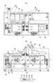
- Figure 4 shows a first heat treatment system using the superheated steam generation unit of Figure 1, (A) being a top view and (B) being a front view.
- one heat treatment unit 3 is provided for two superheated steam generating units, i.e., superheated steam generating units 1-1 and 1-2, as in FIG. 1, but the number of superheated steam generating units is not limited to this.
- a common power supply unit 43 is provided for the grease trap 41, saturated steam generating unit 42, and superheated steam generating units 1-1 and 1-2.
- the saturated steam generating unit 42 heats hot water, for example at about 80°C, to generate saturated steam at about 100°C to 120°C for the superheated steam generating units 1-1 and 1-2, and is relatively small and electrically driven.
- An example of the saturated steam generating unit 42 is a light boiler manufactured by Nakamoto Co., Ltd., model number trademark NBC2101R.
- the saturated steam from the saturated steam generating unit 42 is supplied to the saturated steam inlet 11a of the superheated steam generating units 1-1 and 1-2 via a solenoid valve (not shown).
- the thermal treatment unit 3 has a pyrolysis chamber 31, a screw 32 in the pyrolysis chamber 31, a screw conveyor drive shaft 33, and a geared motor 33' that drives the screw conveyor drive shaft 33.
- a hopper 34 is provided above the pyrolysis chamber 31 to feed the material to be treated into the pyrolysis chamber 31.
- thermal decomposition The oxygen concentration dissolved in normal water at room temperature is about 0.6%. When water is converted into saturated steam, the volume increases by 1600 times. Therefore, the oxygen concentration in the superheated steam Q1 in the thermal decomposition chamber 3 is 0.1 to 0.2%, and as a result, the thermal decomposition chamber 3 becomes almost oxygen-free. Therefore, even if the material to be treated is heated by superheated steam Q1 or far-infrared light H1 at 700°C to 800°C, it is not oxidized or burned, but is instantly decomposed and rendered harmless. This decomposition is called thermal decomposition.
- the heat transfer of the superheated steam Q1 or far-infrared light H1 to the material to be treated is achieved by convection heat transfer as well as the most characteristic condensation heat transfer effect, so that the superheated steam Q1 or far-infrared light H1 acts as thermal energy with high thermal efficiency.
- the condensation heat transfer effect is when the temperature of the material being heat-treated is lower than 100°C, the superheated steam Q1 or far-infrared light H1 condenses on the material, and the condensation temperature due to the large amount of condensation heat provided is 100°C, so the material shows a temperature rise similar to that of being heated in boiling water. The amount of condensation is greater the lower the material is, and condensation continues until the material reaches 100°C. In this superheated steam treatment, the material reaches 700°C to 800°C in a short time, and when the falling drying rate period begins, the temperature of the material begins to rise above 100°C.
- the material to be treated is fed from the hopper 34 into the pyrolysis chamber 31 and stirred by the screw 32, while pyrolysis proceeds with the superheated steam Q1 and far-infrared light H1 from the superheated steam generating units 1-1 and 1-2.
- Water is extracted at the beginning of pyrolysis and falls into the drain pot 34' after high-temperature sterilization. The water that falls into the drain pot 34' can be recycled. In addition, the oil that falls into the drain pot 34' is sent to the grease trap 41.
- the dry distillation gas G generated at the same time is passed through the dry distillation gas discharge pipe 35 to a cyclone 36 for separating dust, and then to a hot water heat exchanger 36', where it is condensed and liquefied in a liquefaction heat exchanger 36".
- the dry distillation gas G is a volatile substance obtained at the same time as thermally decomposing non-volatile solid organic matter by igniting it in the absence of air.
- the oil obtained in the liquefaction heat exchanger 36" is sent to a grease trap 41, while the hot water obtained is sent to a saturated steam generation unit 42, contributing to energy saving in the saturated steam generation unit 42.
- the condensed liquid is treated in a wastewater treatment machine (not shown) and then discharged. Valuable resources such as oil contained in the condensed and liquefied liquid can be recycled after oil separation and purification in the grease trap 41.
- the pyrolyzed residue R is transported from the residue discharge gate 37 via the discharge conveyor 38 to the stockyard 39.
- the metals, stones, carbides, etc. transported to the stockyard 39 can be recycled.
- the control unit 4 controls the entire heat treatment system of FIG. 4.
- the control unit 4 is composed of a computer including a central processing unit (CPU), random access memory (RAM), read-only memory (ROM), flash memory, analog/digital (A/D) converter, D/A converter, input/output interface, etc.
- the control unit 4 receives temperature from the temperature sensors 16 of the superheated steam generation units 1-1 and 1-2 to control the hairpin-shaped conductive hollow tube heaters 12 of the superheated steam generation units 1-1 and 1-2, and also controls each part of the heat treatment unit 3.
- the heating temperature of the conductive hollow tube heater 12 using an alloy such as incone, Hastelloy, or stainless steel is about 800°C to 900°C
- the superheated steam is about 700°C to 800°C. Therefore, the materials to be treated are organic materials such as industrial waste, for example sludge, especially materials with a high carbon content, charcoal, bamboo charcoal, coffee dregs, discarded tofu, plant seeds, etc., and by setting the temperature at the appropriate level, the drying process, carbonization process, carbonization process, and activation process can be carried out.
- organic sludge can be appropriately treated to produce biomass.
- the heat treatment unit 3 is provided so as to be connected to the heating plate 14 of the superheated steam generating units 1-1 and 1-2, but it may also be provided in the superheated steam generating units 1-1 and 1-2 that do not have the heating plate 14. In this case, the effect of the far-infrared light H1 is lost, and only the effect of the superheated steam Q1 remains.
- Figure 5 shows a second heat treatment system using the superheated steam generation unit of Figure 3, (A) is a top view, and (B) is a front view.
- FIG. 5 two superheated steam generating units are provided, i.e., superheated steam generating units 2-1 and 2-2, as shown in FIG. 3, and one heat treatment unit 3 is provided, but the number of superheated steam generating units is not limited to this.
- the heat treatment unit 3 is provided on the heating plate 24 of the superheated steam generation units 2-1 and 2-2.
- the heating temperature of the high-temperature heater 22 is approximately 1000°C to 1600°C, and the superheated steam Q2 is also approximately 1000°C to 1600°C. Therefore, the treated materials are inorganic materials, in particular, flame retardants and dehydrated cakes (sludge) from home appliances and IT-related parts, and valuable resources such as tin, gold, and copper can also be recycled.
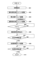
- control unit 4 shown in FIG. 4 and FIG. 5 will be described with reference to the flow chart shown in FIG. All or part of the flowchart in FIG. 6 is stored as a program in the ROM or flash memory of the control unit 4 and executed by a computer.
- step 601 initial settings are made. For example, the appropriate temperature and processing time for the material to be processed are set.
- step 602 the saturated steam generating unit 42 is started.
- step 603 the pyrolysis chamber 31 is started. That is, the geared motor 33' is started to rotate the screw conveyor drive shaft 33. After that, a predetermined amount of material to be treated is manually loaded from the hopper 34 into the pyrolysis chamber 31.
- step 604 superheated steam generation units 1-1, 1-2 or 2-1, 2-2 are started.
- step 605 the temperature T of the temperature sensors 16, 26 (one or both) of the superheated steam generating units 1-1, 1-2 or 2-1, 2-2 is A/D converted and taken in, and it is determined whether T ⁇ T 0 °C or not. For example, T 0 is several hundreds of degrees C. Only when T ⁇ T 0 °C is the process proceeded to step 606.
- step 606 a solenoid valve (not shown) between the saturated steam generating unit 42 and the superheated steam generating units 1-1, 1-2 or 2-1, 2-2 is turned on, and saturated steam is supplied from the saturated steam generating unit 42 to the saturated steam inlet 11a (see FIG. 1) of the superheated steam generating units 1-1, 1-2 or 2-1, 2-2.
- the superheated steam Q1 or Q2 of the superheated steam generating units 1-1, 1-2 or 2-1, 2-2 reaches an appropriate temperature, for example, several hundred degrees Celsius higher than T0 .
- a timer for the initially set processing time is started in step 608.
- the cyclone 36, the hot water heat exchanger 36', and the liquefaction heat exchanger 36" are also started.
- step 609 it is determined whether the processing time set by the timer has elapsed, and after the processing time has elapsed, the heat treatment is terminated in step 610.
- the saturated steam generating unit 42, the superheated steam generating units 1-1, 1-2 or 2-1, 2-2, the cyclone 36, the hot water heat exchanger 36', the liquefaction heat exchanger 36", etc. are stopped.
- a step of monitoring the temperature of the temperature sensor 26 of the high-temperature heater 23 is added between steps 607 and 608.
- the process proceeds to step 608.
- step 609 in FIG. 6 the water extraction process of the pyrolyzed processed product, the solidification and liquefaction process of the dry distillation product, and the transport of the residue to the stockyard 39 are carried out.
- the heat treatment unit 3 is provided so as to be connected to the heating plate 24 of the superheated steam generating units 2-1 and 2-2, but it may also be provided in the superheated steam generating units 2-1 and 2-2 that do not have the heating plate 24. In this case, the effect of the far-infrared light H2 is lost, and only the effect of the superheated steam Q2 remains.
- the superheated steam generation units 1-1, 1-2 or 2-1, 2-2 and the heat treatment unit 3 are arranged vertically, but they may also be arranged horizontally.
- the heat treatment systems shown in Figures 4 and 5 are relatively large and have superheated steam generation units 1-1, 1-2 or 2-1, 2-2, and are suitable for use in facilities that treat organically polluted wastewater from sewage treatment plants, food factories, paper and pulp factories, etc., and for facilities that treat inorganically polluted wastewater from civil engineering construction sites, water purification plants, metal plating factories, etc.
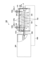
- FIG. 7 shows a third heat treatment system using one superheated steam generating unit of FIG. 1 or FIG. 3, (A) being a top view, (B) being a front view, and FIG. 8 being a right side view showing a partial cross section of the third heat treatment system of FIG. 7.
- This third heat treatment system is relatively small. For example, it is suitable for, but not limited to, the treatment of medical waste.
- Burners use fuel derived from fossil fuels, which raises issues such as the problem of global warming caused by carbon dioxide emissions from the burning of fossil fuels, and the generation of other harmful gases, particularly the need to deal with the generation of highly toxic carbon monoxide caused by incomplete combustion.
- gas plants pose problems such as the risk of explosion and high manufacturing costs.
- one heat treatment unit 3' is provided for the superheated steam generation unit 1 or 2 in Figure 1 or 3, but the number of superheated steam generation units is not limited to this.
- the thermal treatment unit 3' has a pyrolysis chamber 31', but is smaller in size because it does not have the screw 32, screw conveyor drive shaft 33, and geared motor 33' that drives the screw conveyor drive shaft 33 shown in Figures 4 and 5. Also, instead of the hopper 34 shown in Figures 4 and 5, a processing material inlet 44 is provided on the side wall of the pyrolysis chamber 31'.
- the superheated steam Q1 (Q2) and far-infrared light H1 (H2) from the superheated steam generating unit 1 (2) cause the material to be pyrolyzed.
- the material to be treated is medical waste, combustible waste such as organs removed from surgery and waste, diapers generated at nursing care sites, and defective medicines will be pyrolyzed.
- Water is extracted at the beginning of the pyrolysis process and falls into the drain pot 34' after high-temperature sterilization. The water that falls into the drain pot 34' can be recycled. Furthermore, oil that falls into the drain pot 34' is sent to the grease trap 41.
- the dry distillation gas G generated at the same time is condensed and liquefied in the liquefaction heat exchanger 36" via the dry distillation gas discharge pipe 35, the cyclone 36 for separating dust, and the hot water heat exchanger 36'.
- the condensed liquid is treated by the wastewater treatment unit 45 and then discharged.
- the dry distillation gas G is a volatile substance obtained at the same time as the thermal decomposition of non-volatile solid organic matter by ignition in the absence of air.
- the oil obtained in the liquefaction heat exchanger 36" is sent to the grease trap 41, and the hot water obtained is sent to the saturated steam generation unit 42, contributing to the energy saving of the saturated steam generation unit 42. Therefore, no odor or gas is generated.
- Valuable resources such as oil contained in the condensed and liquefied liquid can be recycled after oil separation and purification in the grease trap 41.
- the pyrolyzed residue R is transported from the residue discharge gate 37 via the discharge conveyor 38 to the stockyard 39.
- the metals, stones, carbides, etc. transported to the stockyard 39 can be recycled.
- the control unit 4' controls the entire heat treatment system shown in Figures 7 and 8.
- the control unit 4' receives the temperature from the temperature sensor 16 of the superheated steam generation unit 1 (2) and controls the hairpin-shaped conductive hollow tube heater 12 of the superheated steam generation unit 1 (2), and also controls each part of the heat treatment unit 3'.
- control unit 4' in Figures 7 and 8 is also performed based on the flowchart in Figure 6, but in step 603, a predetermined amount of material to be treated is simply manually fed into the pyrolysis chamber 31' through the material to be treated inlet 44.
- rectangular heat insulating structures 11 and 21 in Figures 1 and 3 do not have to be rectangular.
- they may be polygonal or cylindrical.
- the processed materials in Figures 4, 5, 7, and 8 include frozen food ingredients, raw materials such as coal, wood, and bamboo. Frozen food ingredients can be thawed by processing, making them suitable for convenience store vendors. By processing raw materials such as coal, wood, and bamboo, gas fuel, anthracite, activated carbon, charcoal, bamboo charcoal, etc. can be separated.
Landscapes
- Engineering & Computer Science (AREA)
- Mechanical Engineering (AREA)
- General Engineering & Computer Science (AREA)
- Life Sciences & Earth Sciences (AREA)
- Sustainable Development (AREA)
- Sustainable Energy (AREA)
- Physics & Mathematics (AREA)
- Thermal Sciences (AREA)
- Processing Of Solid Wastes (AREA)
Priority Applications (1)
| Application Number | Priority Date | Filing Date | Title |
|---|---|---|---|
| JP2024523209A JP7587903B1 (ja) | 2023-04-03 | 2024-01-26 | 過熱蒸気発生ユニット及びこれを用いた熱処理システム |
Applications Claiming Priority (2)
| Application Number | Priority Date | Filing Date | Title |
|---|---|---|---|
| JP2023059858 | 2023-04-03 | ||
| JP2023-059858 | 2023-04-03 |
Publications (1)
| Publication Number | Publication Date |
|---|---|
| WO2024209770A1 true WO2024209770A1 (ja) | 2024-10-10 |
Family
ID=92973065
Family Applications (1)
| Application Number | Title | Priority Date | Filing Date |
|---|---|---|---|
| PCT/JP2024/002437 Ceased WO2024209770A1 (ja) | 2023-04-03 | 2024-01-26 | 過熱蒸気発生ユニット及びこれを用いた熱処理システム |
Country Status (2)
| Country | Link |
|---|---|
| JP (1) | JP7587903B1 (https=) |
| WO (1) | WO2024209770A1 (https=) |
Citations (4)
| Publication number | Priority date | Publication date | Assignee | Title |
|---|---|---|---|---|
| JPH07293754A (ja) * | 1994-04-19 | 1995-11-10 | Howa Sangyo:Kk | 配管支持金具用保温具 |
| JP2008075891A (ja) * | 2006-09-19 | 2008-04-03 | Tatsumi Ono | 過熱蒸気生成噴射装置及び過熱蒸気を熱源とする熱処理装置 |
| JP2018009764A (ja) * | 2016-07-15 | 2018-01-18 | トクデン株式会社 | 過熱水蒸気供給ユニット |
| JP7323145B1 (ja) * | 2022-12-23 | 2023-08-08 | 有限会社ティエスエンジニアリング | 過熱蒸気を用いた温水ボイラ装置 |
-
2024
- 2024-01-26 JP JP2024523209A patent/JP7587903B1/ja active Active
- 2024-01-26 WO PCT/JP2024/002437 patent/WO2024209770A1/ja not_active Ceased
Patent Citations (4)
| Publication number | Priority date | Publication date | Assignee | Title |
|---|---|---|---|---|
| JPH07293754A (ja) * | 1994-04-19 | 1995-11-10 | Howa Sangyo:Kk | 配管支持金具用保温具 |
| JP2008075891A (ja) * | 2006-09-19 | 2008-04-03 | Tatsumi Ono | 過熱蒸気生成噴射装置及び過熱蒸気を熱源とする熱処理装置 |
| JP2018009764A (ja) * | 2016-07-15 | 2018-01-18 | トクデン株式会社 | 過熱水蒸気供給ユニット |
| JP7323145B1 (ja) * | 2022-12-23 | 2023-08-08 | 有限会社ティエスエンジニアリング | 過熱蒸気を用いた温水ボイラ装置 |
Also Published As
| Publication number | Publication date |
|---|---|
| JP7587903B1 (ja) | 2024-11-21 |
| JPWO2024209770A1 (https=) | 2024-10-10 |
Similar Documents
| Publication | Publication Date | Title |
|---|---|---|
| US6619214B2 (en) | Method and apparatus for treatment of waste | |
| US7832343B2 (en) | Pyrolyzer with dual processing shafts | |
| EP2449309B1 (en) | Waste management system | |
| US20140223908A1 (en) | Waste Management System | |
| JP5148809B2 (ja) | 汚泥の燃料化方法及び装置 | |
| CN108613194B (zh) | 一种用于村镇生活垃圾焚烧的装置 | |
| CN105371280B (zh) | 一种固废有机物质清洁焚烧的装置与方法 | |
| JP2006328101A (ja) | 有機物の乾燥炭化装置 | |
| RU2508503C2 (ru) | Способ эксплуатации установки для производства биоэтанола | |
| JP7587903B1 (ja) | 過熱蒸気発生ユニット及びこれを用いた熱処理システム | |
| US20160017233A1 (en) | System and Method for Pyrolysis of a Biomass | |
| JP2015224795A (ja) | 有機物の燃料ガス化発生装置とその熱利用 | |
| US7621225B2 (en) | Method and apparatus for treatment of waste | |
| JP6319931B1 (ja) | パームefb熱分解ガス化発電システム | |
| KR101252289B1 (ko) | 가축 폐수 고형물 처리장치 | |
| KR101613968B1 (ko) | 초고온슬러지 건조장치를 갖는 스팀발전시스템 | |
| KR101311849B1 (ko) | 유기폐기물 처리용 친환경 탄화장치 | |
| CN219283341U (zh) | 一种生活垃圾高温碳化装置 | |
| WO2011014094A1 (ru) | Способ и устройство для утилизации влажных отходов, содержащих органические материалы | |
| JPH0522809B2 (https=) | ||
| CN105805756B (zh) | 垃圾环保高效热解装置 | |
| CN105805755B (zh) | 垃圾渐进分级热解聚能增效方法 | |
| KR102589309B1 (ko) | 간접 가열식 연속 열분해 장치 | |
| WO2017141051A1 (en) | Burner | |
| RU2573137C1 (ru) | Способ переработки и утилизации отходов |
Legal Events
| Date | Code | Title | Description |
|---|---|---|---|
| WWE | Wipo information: entry into national phase |
Ref document number: 2024523209 Country of ref document: JP |
|
| 121 | Ep: the epo has been informed by wipo that ep was designated in this application |
Ref document number: 24784573 Country of ref document: EP Kind code of ref document: A1 |
|
| NENP | Non-entry into the national phase |
Ref country code: DE |
|
| 122 | Ep: pct application non-entry in european phase |
Ref document number: 24784573 Country of ref document: EP Kind code of ref document: A1 |