WO2024209709A1 - 装着支援装置 - Google Patents
装着支援装置 Download PDFInfo
- Publication number
- WO2024209709A1 WO2024209709A1 PCT/JP2023/022179 JP2023022179W WO2024209709A1 WO 2024209709 A1 WO2024209709 A1 WO 2024209709A1 JP 2023022179 W JP2023022179 W JP 2023022179W WO 2024209709 A1 WO2024209709 A1 WO 2024209709A1
- Authority
- WO
- WIPO (PCT)
- Prior art keywords
- component
- blobs
- mounting
- area
- components
- Prior art date
- Legal status (The legal status is an assumption and is not a legal conclusion. Google has not performed a legal analysis and makes no representation as to the accuracy of the status listed.)
- Ceased
Links
Images


Classifications
-
- H—ELECTRICITY
- H05—ELECTRIC TECHNIQUES NOT OTHERWISE PROVIDED FOR
- H05K—PRINTED CIRCUITS; CASINGS OR CONSTRUCTIONAL DETAILS OF ELECTRIC APPARATUS; MANUFACTURE OF ASSEMBLAGES OF ELECTRICAL COMPONENTS
- H05K13/00—Apparatus or processes specially adapted for manufacturing or adjusting assemblages of electric components
- H05K13/08—Monitoring manufacture of assemblages
- H05K13/081—Integration of optical monitoring devices in assembly lines; Processes using optical monitoring devices specially adapted for controlling devices or machines in assembly lines
- H05K13/0813—Controlling of single components prior to mounting, e.g. orientation, component geometry
-
- H—ELECTRICITY
- H05—ELECTRIC TECHNIQUES NOT OTHERWISE PROVIDED FOR
- H05K—PRINTED CIRCUITS; CASINGS OR CONSTRUCTIONAL DETAILS OF ELECTRIC APPARATUS; MANUFACTURE OF ASSEMBLAGES OF ELECTRICAL COMPONENTS
- H05K13/00—Apparatus or processes specially adapted for manufacturing or adjusting assemblages of electric components
- H05K13/04—Mounting of components, e.g. of leadless components
- H05K13/043—Feeding one by one by other means than belts
Definitions
- the present invention relates to a wearing assistance device.
- the mounting assistance device supports the mounting process by a component mounting machine using a bulk feeder.
- the bulk feeder is equipped to the component mounting machine that mounts components on a board, and supplies components in a bulk state (see Patent Document 1).
- the component mounting machine executes image processing to recognize the state of component supply by the bulk feeder, and controls the component suction operation using a suction nozzle based on the results of this image processing.
- the image processing for recognizing the supply status includes a determination of whether or not the components supplied to the supply area of the bulk feeder are suitable for the component placement machine to pick up. If there is an erroneous determination in this type of image processing, it can lead to an error in the picking operation, and even if the components are picked up, it could affect subsequent processing.
- the present specification aims to provide a mounting assistance device that supports the mounting process by improving the accuracy of image processing that recognizes the supply status of parts by a bulk feeder.
- an attachment assistance device that includes a recognition unit that recognizes the components in the supply area by performing image processing including a generation step of generating multiple blobs for image data acquired by imaging a supply area where multiple components are supplied in bulk, an extraction step of extracting candidate blobs from the multiple blobs that correspond to at least a partial closed area of the components, and a recognition step of recognizing a rectangular area containing one or more of the candidate blobs as the components in the image data, and a determination unit that determines whether the recognized components are suitable for a picking operation by a component attachment machine based on the total area of the one or more candidate blobs contained in the rectangular area.
- This configuration can improve the accuracy of image processing. This can prevent mistakes during the component mounting machine's picking operation, and as a result, the component mounting machine can maintain high productivity.
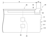
- FIG. 2 is a plan view showing a schematic diagram of the component mounting machine;
- FIG. 2 is a side view showing a schematic of a portion of a bulk feeder including a feeding area.
- FIG. 3 is a plan view seen from a direction III in FIG. 2 .
- 1 is a block diagram showing a component mounting machine to which a mounting assistance device is applied;
- 13 is a flowchart showing a supply state recognition process.
- FIG. 13 is a diagram showing image data obtained by capturing an image of a supply region.
- FIG. 13 is an enlarged view showing image data on which a blob generation process has been executed.
- FIG. 8A showing an aspect in which the entire part including the body has become a blob through binarization processing
- 8B is an enlarged view corresponding to FIG. 8A, showing a state in which a foreign substance adhering to a supply region has become a blob through binarization processing
- FIG. 1 is an explanatory diagram showing a virtual part recognized as a blob in image data.
- 11 is a flowchart showing a first aspect of a process for determining whether a blob is good or bad.
- 13 is a flowchart showing a second aspect of the process for determining whether a blob is good or bad.
- the mounting assist device 50 assists the mounting process by the component mounting machine 10 using the bulk feeder 30.
- the mounting assist device 50 is incorporated into the control device 20 of the component mounting machine 10.
- the mounting assist device 50 improves the accuracy of image processing for recognizing the supply state of components supplied by the bulk feeder 30, thereby suppressing the occurrence of errors in the picking operation in the mounting process.
- the component mounting machine 10 described above performs a mounting process for mounting components on the board 91 as a specified substrate-related operation.
- the component mounting machine 10 is installed in the transport direction of the board 91 together with other substrate-related operation machines to form a production line.
- Each of the multiple substrate-related operation machines is communicatively connected to a host computer 60 (see FIG. 4) that controls the production line as a whole.
- the production line includes, for example, a printing machine, the component mounting machine 10, a reflow furnace, and an inspection machine as multiple substrate-related operation machines.
- Board transport device 11 1 the component mounting machine 10 includes a board transport device 11.
- the board transport device 11 sequentially transports boards 91 in a transport direction and positions the boards 91 at predetermined positions within the machine.
- the component mounting machine 10 includes a component supplying device 12.
- the component supplying device 12 supplies components to be mounted on the board 91.
- the component supplying device 12 has feeders 122 set in a plurality of slots 121.
- the feeders 122 may be, for example, a tape feeder that feeds and moves a carrier tape containing a large number of components to supply the components so that they can be picked.
- the feeders 122 may be, for example, a bulk feeder 30 that supplies components stored in a bulk state so that they can be picked. Details of the bulk feeder 30 will be described later.
- the component mounting machine 10 includes a component transfer device 13.
- the component transfer device 13 transfers the components supplied by the component supply device 12 to a predetermined mounting position on the board 91.
- the component transfer device 13 includes a head drive device 131, a movable table 132, a mounting head 133, and a suction nozzle 134.
- the head drive device 131 moves the movable table 132 in the horizontal direction (X direction and Y direction) by a linear motion mechanism.
- the mounting head 133 is detachably fixed to the movable table 132 by a clamp member (not shown) and is provided so as to be movable horizontally within the machine.
- the mounting head 133 supports multiple suction nozzles 134 that are rotatable and movable up and down.
- the suction nozzles 134 are holding members that pick up and hold the parts supplied by the feeder 122.
- the suction nozzles 134 use the supplied negative pressure air to pick up the parts supplied by the feeder 122.
- a chuck that holds the parts by gripping them can be used as the holding member attached to the mounting head 133.
- the component mounting machine 10 includes a component camera 14 and a board camera 15.
- the component camera 14 and the board camera 15 are digital imaging devices having imaging elements such as CMOS.
- the component camera 14 and the board camera 15 capture images based on a control signal and send image data acquired by the capture.
- the component camera 14 is configured to be able to capture images of the components held by the suction nozzle 134 from below.
- the board camera 15 is provided on a moving stage 132 so as to be movable in the horizontal direction integrally with the mounting head 133.
- the board camera 15 is configured to be able to capture images of the board 91 from above.
- the board camera 15 can also image various devices within the movable range of the movable stage 132.
- the board camera 15 can image the supply area As where the bulk feeder 30 supplies components and the reference mark 49 provided on the upper part of the bulk feeder 30 within the camera's field of view. In this way, the board camera 15 can be used to image different objects in order to obtain image data to be used for various image processing.
- Control device 20 The component mounting machine 10 includes a control device 20 as shown in Fig. 1.
- the control device 20 is mainly composed of a CPU, various memories, and a control circuit.
- the control device 20 includes a storage unit 21 as shown in Fig. 4.
- the storage unit 21 is composed of a storage device such as a hard disk device or a flash memory.
- the storage unit 21 of the control device 20 stores various data such as a control program M1 used to control the mounting process, component data M2, and cavity information M3.
- Control program M1 indicates the mounting positions, mounting angles, and component types of components to be mounted on board 91 in the planned mounting order during the mounting process.
- the mounting process includes a process of repeating a PP cycle (pick-and-place cycle), which includes a collection cycle and a mounting cycle, multiple times.
- the above-mentioned “collection cycle” refers to a process of repeating a collection operation, in which components supplied by component supply device 12 are picked up by suction nozzle 134, multiple times.
- the above-mentioned “mounting cycle” refers to a process in which a mounting operation is repeated multiple times to mount the picked component at a predetermined mounting position on the board 91 at a predetermined mounting angle.
- the control program M1 has preset an execution order for the PP cycle, which is made up of multiple picking and mounting operations grouped together in consideration of the number of suction nozzles 134 supported by the mounting head 133, the travel distance of the mounting head 133, etc.
- Component data M2 includes shape data for each type of component.
- shape data includes at least one of the outer edge shape of the component, the shape of the characteristic part of the component, and the dimensions of the component.
- the "outer edge shape” of a component corresponds to the shape of the outer edge when the inside of the component and the background are separated using the outer edge as the boundary.
- the "shape of the characteristic part" of a part corresponds to the boundary shape of the characteristic part on the appearance resulting from the part's shape, pattern, color, etc.
- the characteristic part of a part may be the corners, bumps, terminals, leads, etc. of the part.
- the part data M2 may also include, for example, the maximum allowable movement speed (acceleration) for each part, the pick-up position (for example, the position of contact with the suction nozzle 134), etc.
- the component data M2 includes information indicating whether the entire component will be a blob (see FIG. 8B) or whether the body 93 of the component will be black and the electrode portion 94 (terminal, etc.) will be a blob (see FIG. 8A) when image data acquired by photographing the component is binarized using a predetermined threshold value in the blob analysis described below.
- Cavity information M3 is information about cavities 45 that are formed in the supply area As of bulk feeder 30 and that individually accommodate components, associated with the identification information (ID) of bulk feeder 30.
- Cavity information M3 may include the shape (including the length of each side and depth), position, orientation, and type of corresponding component of cavity 45 in supply area As. Details of the process using cavity information M3 will be described later.
- the control device 20 executes a process for recognizing the holding state of the components held by each of the multiple holding members (suction nozzles 134). Specifically, the control device 20 processes image data acquired by imaging with the component camera 14, and recognizes the position and angle of each component relative to the reference position of the mounting head 133. Note that in addition to the component camera 14, the control device 20 may also process image data acquired by imaging the components from the side, below, or above using, for example, a head camera unit that is integrally provided with the mounting head 133.
- the control device 20 controls the mounting operation by the mounting head 133 so that the component is mounted on the board 91 in a specified orientation. At this time, the control device 20 controls the mounting operation based on the recognized holding state of the component. In other words, the control device 20 corrects the position of the mounting head 133 and the angle of the suction nozzle 134 about the Q axis so as to correct the position and angle deviation of the component held by the suction nozzle 134 with respect to the Q axis (the rotation axis of the suction nozzle 134). As a result, the component held by the suction nozzle 134 is mounted at a specified mounting angle in a specified mounting position instructed by the control program M1.
- Bulk feeder 30 is set in component mounting machine 10 and functions as part of component supply device 12. Bulk feeder 30 supplies components housed in component cases in a bulk state (loose and irregular in each position) that is not packaged like a carrier tape. Therefore, unlike tape feeders, bulk feeder 30 does not use carrier tape, and therefore has the advantage of being able to omit loading of carrier tape and collection of used tape.
- Some types of bulk feeders 30 supply components in irregular positions to the planar supply area As. However, if the components are so close together in the supply area As that they are touching each other, or if they are piled up (overlapping vertically), or if the components are in a horizontal position with their width direction aligned vertically, the component mounting machine 10 cannot pick up these components. Therefore, to increase the proportion of components that can be picked up, some types of bulk feeders 30 supply components in an aligned state in the supply area As. In this embodiment, a bulk feeder 30 that aligns components will be described as an example.
- the bulk feeder 30 has a track unit 40 that is vibrable and detachable from the feeder body 31, which is formed in a flat box shape.
- a connector 311 and two positioning pins 312 are provided at the front of the feeder body 31 (the right end in FIG. 2).
- the feeder body 31 When the feeder body 31 is set in the slot 121 of the component supply device 12, it is powered via the connector 311 and is capable of communicating with the control device 20 of the component mounting machine 10.
- the track unit 40 is vibrated by the vibration device 35.
- the track unit 40 is formed with a transport path R along which multiple parts are transported, and a supply area As that is connected to the transport path R and opens upward so that multiple parts can be picked up.
- the track unit 40 is formed to extend in the front-to-rear direction (left-to-right direction in Figure 3) of the feeder body 31.
- a pair of side walls 46 that protrude upward are formed on both edges of the track unit 40 in the width direction (top-bottom direction in Figure 3).
- the pair of side walls 46, together with the tip 47 of the track unit 40 are wall members that surround the periphery of the transport path R and prevent leakage of parts transported on the transport path R.
- a plurality of cavities 45 are formed in the supply area As of the track unit 40.
- Each of the cavities 45 opens upward and accommodates components in a position in which the thickness direction of the components is the vertical direction.
- the cavities 45 are arranged in a staggered pattern.
- the "supply area As" of the track unit 40 is an area where components are supplied in bulk, and where components can be picked up by the suction nozzle 134 supported by the mounting head 133.
- the "transport path R" of the track unit 40 is a path along which parts that have circulated from the component case side to the track unit 40 are transported to the supply area As.
- the vibration device 35 also applies vibrations to the track unit 40 so that the multiple parts are transported along the transport path R.
- a forward and upward external force, or a rearward and upward external force is applied to the parts.
- the multiple parts are transported to the front or rear of the track unit 40.
- the bulk feeder 30 controls the operation of the vibration device 35 by the feeder control device 36 to transport the parts and perform the operation of supplying the parts to the supply area As.
- the parts are stored in the multiple cavities 45 by the supply operation, and the suction nozzle 134 is ready to pick up the parts.
- a shutter 48 capable of closing the opening of the supply area As is provided on the top of the track unit 40.
- the shutter 48 is in a state in which its opening and closing operation is controlled by a shutter drive device (not shown).
- a shutter drive device not shown.
- the mounting support device 50 supports the component supply state recognition process executed by the control device 20 of the component mounting machine 10 in the mounting process.
- the supply state recognition process includes image processing, and this image processing includes a determination as to whether or not the component supplied to the supply area As of the bulk feeder 30 is suitable for the picking operation by the component mounting machine 10.
- control device 20 processes image data D1 (see FIG. 6) acquired by imaging with a camera (in this embodiment, the board camera 15), recognizes whether there is a component suitable for the collection operation in the supply area As, and if there is a component suitable for the collection operation, recognizes the position and angle of that component. Then, the control device 20 controls the operation of the mounting head 133 in the collection operation based on the results of the supply status recognition process.
- the position and orientation of the recognized part (hereinafter also referred to as the "recognized part") will differ from the actual one, which may cause an error in the picking operation. Furthermore, even if the part can be picked, there is a risk that it will affect the processing that is executed afterwards, such as the part transfer operation or mounting operation.
- the mounting assistance device 50 incorporated in the control device 20 of the component mounting machine 10 employs a configuration that can improve the accuracy of the image processing included in the recognition process of the component supply state (see FIG. 5).
- the mounting assistance device 50 includes a recognition unit 51 and a determination unit 52.
- the mounting assistance device 50 acquires image data D1 acquired by imaging with the board camera 15 (S11).
- the recognition unit 51 executes recognition processing (S20) using the image data D1.
- the determination unit 52 executes determination processing (S30) as to whether or not the component is suitable for the collection operation.
- Recognition unit 51 The recognition unit 51 performs image processing on image data D1 acquired by imaging the supply area As in which a plurality of cavities 45 are formed, each of which accommodates a plurality of components 92, to acquire information about the recognized components 80.
- blob analysis is used as a method for recognizing the components 92 scattered in the supply area As as the recognized components 80.
- the recognition unit 51 first executes a generation step (S21) of generating a number of blobs 70 from the image data D1.
- the recognition unit 51 binarizes the image data D1 using a predetermined threshold, and for example, colors each pixel white when its brightness value is higher than the threshold, and black when its brightness value is equal to or lower than the threshold.
- Figure 7 shows an enlarged portion of the binarized image data D1, with the pre-processing cavity 45 indicated by a dashed line.
- the blobs 70 correspond to closed white regions in the binarized image data D1.
- the blob 70 may refer to, for example, a pair of electrode portions 94 formed at both ends of the longitudinal direction of the part 92, as shown in FIG. 8A, or may refer to the entire part 92 including the body 93, as shown in FIG. 8B. These differ depending on the type of part 92 (including the color and gloss of the body 93 and electrode portions 94) and the threshold value used for binarization.
- the recognition process (S20) recognizes the part 92 using one or two blobs 70. Note that the mounting assistance device 50 can determine in which way the blob 70 is formed, based on the part data M2.
- the blobs 70 in the binarized image data D1 may include, for example, parts 92 that are not housed in the cavity 45 or foreign objects 89 (see FIG. 6). If these defective blobs 72, 73 are mistaken for part of the part 92, the accuracy of the recognition process will decrease. Therefore, the recognition unit 51 extracts candidate blobs 71 that are suitable for the recognition process from among the multiple blobs 70 (S22). In other words, this extraction step is a process of removing blobs 70 (72, 73) that are unsuitable for the recognition process.
- the recognition unit 51 extracts candidate blobs 71 whose respective center positions 75 of the multiple blobs 70 are included in a suitable region Rh defined based on the positions of the multiple cavities 45 (S22). In detail, the recognition unit 51 first obtains the center position 75 of each of the multiple blobs 70.
- the center position 75 may be the center of the circumscribing rectangle of the blob 70, or may be the center of gravity of the circumscribing rectangle.
- the "appropriate region Rh" defined based on the position of the cavity 45 is a region that takes into account a tolerance in the region in which the center of the blob 70 corresponding to the part 92 may exist relative to the cavity 45 when the part 92 is contained in the cavity 45, and is set to, for example, a region of the same shape as the cavity 45.
- the recognition unit 51 extracts, as candidate blobs 71, blobs 70 whose center positions fall within the appropriate region Rh that is set based on the cavity information M3 (as shown in the lower part of Figure 9).
- the recognition unit 51 executes a recognition step (S23) in which the recognition unit 51 recognizes a rectangular area including one or more candidate blobs 71 as a part 92 in the image data D1.
- the recognition unit 51 recognizes a rectangular area circumscribing one or more candidate blobs 71 as a part 92 in the image data D1. This allows, for example, a recognition component 80 formed by a pair of candidate blobs 71 or a recognition component 80 formed by one candidate blob 71 to be obtained.
- the recognition unit 51 also recognizes information necessary for subsequent processing, such as the reference position, angle (supply angle), shape (including the lengths of the short and long sides), and area (corresponding to the number of pixels contained in the rectangular area) in the supply area As for each of the multiple recognized components 80. Through this processing, the recognition unit 51 recognizes the supply state of the components 92 in the supply area As, and stores the recognition results in the memory unit 21.
- the above recognition process (S20) is premised on the premise that the component mounting machine 10 only targets components 92 that are properly accommodated in the cavity 45 for the picking operation. Therefore, if the bulk feeder 30 is a type that does not have a cavity 45 in the supply area As, the recognition unit 51 may extract candidate blobs 71, for example, from among the multiple blobs 70, based on conditions such as having a certain range of area and a blob shape that is close to a rectangle, and obtain the position and shape of the recognized component 80 in the supply area As.
- the determination unit 52 determines (S30) whether the component 92 (recognized component 80) recognized in the recognition process (S20) is suitable for the picking operation by the component mounting machine 10 based on the supply state of the component 92.
- the recognized component 80 is recognized in the recognition process (S20) using the candidate blob 71 corresponding to at least a part of the closed region of the component 92, there are cases where the recognized component 80 is not suitable for the picking operation.
- One possible cause of this is that, for example, when two components 92 are housed in cavity 45 with their longitudinal directions aligned vertically, the electrode parts of each component 92 may be mistakenly recognized as the electrode parts of one component 92, resulting in recognition of the recognized component 80. Also, when a component 92 housed in cavity 45 overlaps at least a portion of another component 92, it is possible that the recognition may be erroneous in the same manner as described above.
- the suction nozzle 134 is pressed against the component 92 contained in the cavity 45 to contact and pick it up. At this time, the component 92 is pressed against the bottom surface of the cavity 45, and metal pieces that have fallen off the electrode portion 94 of the component 92 may adhere to the bottom surface of the cavity 45 as foreign matter 89.
- the blob 70 generation step (S21) a plurality of foreign objects 89 will be generated as blobs 70 (bad blobs 73), as shown in FIG. 8C.
- the foreign objects 89 that have adhered as described above adhere to the area where the electrode portion 94 of the part 92 that is contained in the cavity 45 so as to be able to be collected is located. Therefore, if the recognition part 80 is configured with this bad blob 73 as the candidate blob 71, it may be mistaken for the presence of a part that can be collected.
- modes of suitability determination are adopted, taking into account the above-mentioned possible causes of misidentification.
- the modes of suitability determination (S31, S32) described below can be appropriately combined or some can be omitted, taking into account the type of component 92, the imaging environment, the shape of the supply area As of the bulk feeder 30, etc.
- the determination unit 52 first determines whether the blob 70 is good or bad (S31). Various methods can be used to determine whether the blob 70 is good or bad. As a first method of determining whether the recognized component 80 is suitable for the picking operation by the component mounting machine 10, based on the total area Sb of one or more candidate blobs 71 contained in a rectangular region. More specifically, as shown in FIG. 10, the determination unit 52 first calculates the area Sr of the recognized component 80 (S41). As shown in FIGS. 8A-8C, the areas Sr1-Sr3 of the recognized components 80 correspond to the areas of the respective rectangular regions.
- the determination unit 52 calculates the total area Sb (Sb1-Sb3) of the candidate blobs 71 contained in the rectangular region (S42).
- the candidate blobs 71 contained in the rectangular region is the sum of the individual areas of all the candidate blobs 71 used when forming the recognition component 80.
- the determination unit 52 calculates the ratio of the total area Sb of the candidate blobs 71 to the area Sr of the recognition component 80 (S43). This calculates the area ratio (R1, R2, R3) as shown in Figures 8A-8C.
- the determination unit 52 compares the calculated area ratio (R1, R2, R3) with a preset threshold value Th (S45).
- the threshold value Th is set to different values (Th1, Th2) for a type in which the entire part 92 becomes the candidate blob 71 in the generation step (S21) (see FIG. 8B) and a type in which the electrode portion 94 of the part 92 becomes the candidate blob 71 (see FIG. 8A).
- This threshold value Th differs depending on the type of part supplied by the bulk feeder, and the determination unit 52 switches between the threshold values Th1, Th2 depending on the type of part 92 supplied to determine whether or not it is suitable for the collection operation.
- the threshold values Th1, Th2 may be switched based on the type of part specified in the part data M2, or, if the part data M2 records the proportion of the electrode portion (the part that becomes white due to the binarization process) to the overall dimensions of the part, the threshold value may be set based on this proportion.
- the recognition component 80 when the recognition component 80 is formed of a defective blob 73 corresponding to the foreign object 89 as described above, the above area ratio is smaller than when the recognition component 80 is formed of a candidate blob 71 corresponding to the electrode portion 94 of a normal component 92.
- the determination unit 52 determines that the candidate blob 71 is normal and that the recognition component 80 is suitable for the collection operation (S46).
- the determination unit 52 determines that the candidate blob 71 is a defective blob 73 and that the recognition component 80 is not suitable for the collection operation (S47).
- the determination unit 52 uses the area ratio in the pass/fail determination (S31), but a simpler determination method can be adopted.
- the determination unit 52 determines whether the recognized component 80 is suitable for the picking operation by the component mounting machine 10 based on the total area Sb of the candidate blobs 71 and a preset threshold value Th. More specifically, as shown in FIG. 11, the determination unit 52 first calculates the total area Sb of the candidate blobs 71 contained in a rectangular region (S51).
- the determination unit 52 sets a specified range according to the type of component 92 (S52).
- This "specified range” corresponds to a normal range that takes into account the allowable error of the ratio of the electrode portion (the portion that becomes white due to binarization processing) to the overall dimensions of the component. If the total area Sb is within the specified range (S53: Yes), the determination unit 52 determines that the candidate blob 71 is normal and that the recognition component 80 is suitable for the collection operation (S54). On the other hand, if the total area Sb is outside the specified range (S53: No), the determination unit 52 determines that the candidate blob 71 is a defective blob 73 and that the recognition component 80 is not suitable for the collection operation (S55).
- a specified range is used to evaluate the total area Sb, but the lower limit of the specified range may be a preset threshold, and the pass/fail judgment may be performed by comparing the total area Sb with the threshold.
- an area ratio is used, so even if the size of the recognized component 80 varies depending on its angle or the imaging environment, it can be judged based on its relationship with the total area Sb of the candidate blobs 71, thereby improving the judgment accuracy.
- the pass/fail of the candidate blob 71 can be determined, for example, from the total area Sb of the candidate blob 71 located inside the cavity 45. Therefore, for example, this pass/fail determination can be performed between the extraction step (S22) of the candidate blob 71 and the recognition step (S23). According to this manner, defective blobs 73 can be recognized early, so the generation of unnecessary recognized components 80 can be suppressed. Note that, for example, if there is room for image processing, the first and second manners of pass/fail determination may be performed at different times.
- the judgment unit 52 may also judge the pass/fail of the blob 70 based on whether the shape of the blob 70 (candidate blob 71 after execution of the extraction step) constituting the recognized component 80 resembles the shape corresponding to the closed region of the component 92. In other words, if there is one blob 70, the quality of the blob 70 is judged based on whether it resembles the overall shape of the component 92, and if there are two blobs 70, the quality of the blob 70 is judged based on whether they resemble the shapes of a pair of electrode portions 94 of the component 92, respectively. Also, if there are three or more blobs 70, the quality of the blob 70 is judged based on whether the partial rectangular shape formed by these resembles the overall shape or electrode portions 94 of the component 92.
- the determination unit 52 determines whether the recognized component 80 is a component 92 that has been supplied in a pickable manner in the supply area As (S32). Specifically, the determination unit 52 selectively performs the following determinations (A)-(E). In determination (A), the determination unit 52 determines whether the recognized component 80 can be picked based on whether the reference position of the recognized component 92 (recognized component 80) is present in a specified area. In this embodiment, the reference position of the component 92 (recognized component 80) is set to the center position of the component 92.
- predetermined area is an area that is determined based on the shape of the cavity 45 that accommodates the part 92, and in this embodiment, is set to an area where the center of the part 92 can be located when the part 92 is properly accommodated in the cavity 45. If the reference position of the recognition part 80 is not within the prescribed area, the determination unit 52 determines that the part 92 is not properly accommodated in the cavity 45 and is therefore not suitable for the collection operation.
- the judgment unit 52 judges whether the recognized component 80 can be collected based on a histogram of the pixels of the recognized component 80 in the image data D1. In detail, a histogram of the brightness values of each of the multiple pixels located inside the rectangular shape of the recognized component 80 is generated, and if the shape of the histogram is not similar to that generated for a normal component 92, the judgment unit 52 judges that the recognized component 80 is unsuitable for collection.
- the judgment unit 52 judges whether or not the recognized component 80 can be picked based on the specified angle in the supply area As and the supply angle of the recognized component 92 (recognized component 80).
- the specified angle is an angle specified based on the shape of the cavity 45 that accommodates the component 92, and is, for example, an angle in which the longitudinal direction of the cavity 45 is 0 degrees.
- the supply angle is an angle obtained in the recognition process (S20), and is the angle that the longitudinal direction of the rectangular area circumscribing the candidate blob 71 makes with respect to the reference direction of the supply area As (the Y direction in this embodiment).
- the determination unit 52 determines whether or not the part 92 is suitable for the collection operation based on whether or not the supply angle of the part 92 is within the range of possible angles relative to a specified angle when the part 92 is properly accommodated in the cavity 45.
- the possible range is set in advance based on the shape of the cavity 45 and the shape of the part 92.
- the judgment unit 52 judges whether or not the recognized component 92 (recognized component 80) is suitable for the picking operation by the component mounting machine 10 based on the shape or area of the recognized component 92. In a mode of judging suitability based on area, the judgment unit 52 judges that the component 92 is not suitable for the picking operation by the component mounting machine 10 when the area of the component 92 (recognized component 80) determined based on the number of pixels contained in a rectangular area in the image data D1 is outside a specified range.
- the above-mentioned "specified range” is set to a range that takes into account the apparent area occupied by the component 92 in the image data D1 when a normal component 92 is imaged, and individual differences in manufacturing and tolerances based on the imaging conditions and image processing. If the area based on the number of pixels of the recognized component 80 falls within the specified range, it is judged to be suitable in judgment (D).
- the judgment unit 52 judges that the recognized component 92 (recognized component 80) is not suitable for the picking operation by the component mounting machine 10 when the ratio (aspect ratio) of the short side to the long side of the recognized component 92 (recognized component 80) is outside a specified range.
- the above-mentioned "specified range” is set to a range that takes into account the ratio of the short side to the long side of a normal component 92, individual differences in manufacturing, and tolerances based on imaging conditions and image processing.
- the judgment unit 52 judges whether or not the recognized component 80 in the image data D1 and the degree of containment of the cavity 45 are suitable for the collection operation.
- the judgment unit 52 first recognizes the cavity 45 closest to the component 92 (recognized component 80) in the image data D1. At this time, the judgment unit 52 can recognize the cavity 45 that is estimated to contain the recognized component 80 based on the image data D1 and cavity information M3.
- the determination unit 52 determines whether the entire recognized component 80 is contained in the cavity 45. If a portion of the recognized component 80 is not contained in the cavity 45, the determination unit 52 determines that the component 92 (recognized component 80) is not suitable for the picking operation by the component mounting machine 10. On the other hand, if the entire recognized component 80 is contained in the cavity 45, the determination (E) is determined to be appropriate. Note that the determination of whether the entire recognized component 80 is contained may take into account allowable error in image processing, etc.
- the mounting assistance device 50 obtains judgment results for each of the multiple recognized components 80 as to whether or not it is suitable for the picking operation.
- This judgment result is stored as information indicating, for example, whether or not each of the multiple cavities 45 contains a pickable component 92.
- the pickable components 92 are associated with information such as their reference position (center position) and supply angle.
- the mounting process by the component mounting machine 10 will be described.
- the component supply device 12 is equipped with a bulk feeder 30.
- the control device 20 executes a calibration process to recognize the positions of the multiple cavities 45 in the machine.
- the control device 20 first moves the board camera 15 to above the reference mark 49 of the bulk feeder 30, and obtains image data by capturing an image with the board camera 15.
- control device 20 recognizes the position of the bulk feeder 30 within the machine based on the positions of the pair of reference marks 49 contained in the image data through image processing, and the position of the board camera 15 at the time of image capture.
- the control device 20 can obtain the coordinate values of each cavity 45 based on the results of the calibration process and cavity information M3 indicating the arrangement of the cavities 45.
- the board transport device 11 of the component mounting machine 10 executes a board 91 loading process.
- the board 91 is loaded into the machine and positioned at a predetermined position within the machine.
- the control device 20 causes the bulk feeder 30 to execute a supply operation.
- a state is created in which a plurality of components 92 are contained in at least some of the multiple cavities 45 of the bulk feeder 30.
- the mounting assistance device 50 executes a process to recognize the supply status of the components 92.
- the control device 20 executes a PP cycle.
- the control device 20 executes a picking cycle in which the picking operation of picking up the part 92 using multiple suction nozzles 134 is repeated.
- the control device 20 controls the operation of the mounting head 133 in the picking operation so that the mounting head 133 is sequentially positioned according to the reference position of the pickable part 92.
- the control device 20 determines the angle of the suction nozzle 134 according to the supply angle of the pickable part 92.
- control device 20 executes a process for recognizing the holding state of the components 92 held by each of the multiple suction nozzles 134.
- the control device 20 moves the mounting head 133 above the component camera 14 and sends an image capture command to the component camera 14.
- the control device 20 processes the image data acquired by the component camera 14, and recognizes the attitude (position and angle) of the components 92 held by each of the multiple suction nozzles 134.
- the result of the holding state recognition process is recorded in the memory unit 21 as an operation result indicating whether or not a pick-up error occurred in the pick-up operation.
- the control device 20 executes a mounting cycle in which the mounting operation of mounting components using the multiple suction nozzles 134 is repeated.
- the control device 20 controls the operation of the mounting head 133 so that the components 92 are mounted at the mounting positions specified by the control program M1.
- the control device 20 controls the operation of the mounting head 133 so that the suction nozzles 134 are positioned and angled relative to the mounting positions based on the results of the recognition process.
- the control device 20 also executes supply management processing for the parts 92 in parallel with the above-mentioned PP cycle.
- the supply management processing includes setting the execution timing of the supply operation of the parts 92 by the bulk feeder 30, commanding the supply operation, and supply status recognition processing. For example, when the supply operation of the parts 92 is executed, the supply operation by the bulk feeder 30 is executed in the period from the end of the collection cycle of the current PP cycle to the start of the collection cycle of the next PP cycle. When the supply operation by the bulk feeder 30 is executed, the mounting assistance device 50 executes the above-mentioned supply status recognition processing again.
- the control device 20 executes the unloading process of the board 91.
- the board transport device 11 unclamps the positioned board 91 and unloads the board 91 out of the component mounting machine 10.
- the mounting assist device 50 is configured to be incorporated in the control device 20 of the component mounting machine 10. However, a part or all of the mounting assist device 50 may be incorporated in the host computer 60 or other external device. For example, the mounting assist device 50 may be incorporated in the host computer 60 and may be a dedicated device installed on the production line Ln.
Landscapes
- Engineering & Computer Science (AREA)
- Manufacturing & Machinery (AREA)
- Microelectronics & Electronic Packaging (AREA)
- Operations Research (AREA)
- Supply And Installment Of Electrical Components (AREA)
Priority Applications (2)
| Application Number | Priority Date | Filing Date | Title |
|---|---|---|---|
| JP2025512398A JPWO2024209709A1 (https=) | 2023-04-04 | 2023-06-15 | |
| DE112023006135.1T DE112023006135T5 (de) | 2023-04-04 | 2023-06-15 | Bestückungsunterstützungsvorrichtung |
Applications Claiming Priority (4)
| Application Number | Priority Date | Filing Date | Title |
|---|---|---|---|
| PCT/JP2023/013956 WO2024209546A1 (ja) | 2023-04-04 | 2023-04-04 | 装着支援装置 |
| JPPCT/JP2023/013956 | 2023-04-04 | ||
| JPPCT/JP2023/013957 | 2023-04-04 | ||
| PCT/JP2023/013957 WO2024209547A1 (ja) | 2023-04-04 | 2023-04-04 | 装着支援装置 |
Publications (1)
| Publication Number | Publication Date |
|---|---|
| WO2024209709A1 true WO2024209709A1 (ja) | 2024-10-10 |
Family
ID=92971619
Family Applications (1)
| Application Number | Title | Priority Date | Filing Date |
|---|---|---|---|
| PCT/JP2023/022179 Ceased WO2024209709A1 (ja) | 2023-04-04 | 2023-06-15 | 装着支援装置 |
Country Status (3)
| Country | Link |
|---|---|
| JP (1) | JPWO2024209709A1 (https=) |
| DE (1) | DE112023006135T5 (https=) |
| WO (1) | WO2024209709A1 (https=) |
Citations (5)
| Publication number | Priority date | Publication date | Assignee | Title |
|---|---|---|---|---|
| US5371690A (en) * | 1992-01-17 | 1994-12-06 | Cognex Corporation | Method and apparatus for inspection of surface mounted devices |
| JP2009239150A (ja) * | 2008-03-28 | 2009-10-15 | Fuji Mach Mfg Co Ltd | 電子部品装着装置における部品認識方法 |
| WO2021095221A1 (ja) * | 2019-11-14 | 2021-05-20 | 株式会社Fuji | 部品装着機 |
| WO2021144971A1 (ja) * | 2020-01-17 | 2021-07-22 | 株式会社Fuji | 検査装置及び検査方法 |
| WO2022064585A1 (ja) * | 2020-09-24 | 2022-03-31 | 株式会社Fuji | 採取可否判定装置および採取可否判定方法 |
-
2023
- 2023-06-15 WO PCT/JP2023/022179 patent/WO2024209709A1/ja not_active Ceased
- 2023-06-15 JP JP2025512398A patent/JPWO2024209709A1/ja active Pending
- 2023-06-15 DE DE112023006135.1T patent/DE112023006135T5/de active Pending
Patent Citations (5)
| Publication number | Priority date | Publication date | Assignee | Title |
|---|---|---|---|---|
| US5371690A (en) * | 1992-01-17 | 1994-12-06 | Cognex Corporation | Method and apparatus for inspection of surface mounted devices |
| JP2009239150A (ja) * | 2008-03-28 | 2009-10-15 | Fuji Mach Mfg Co Ltd | 電子部品装着装置における部品認識方法 |
| WO2021095221A1 (ja) * | 2019-11-14 | 2021-05-20 | 株式会社Fuji | 部品装着機 |
| WO2021144971A1 (ja) * | 2020-01-17 | 2021-07-22 | 株式会社Fuji | 検査装置及び検査方法 |
| WO2022064585A1 (ja) * | 2020-09-24 | 2022-03-31 | 株式会社Fuji | 採取可否判定装置および採取可否判定方法 |
Also Published As
| Publication number | Publication date |
|---|---|
| DE112023006135T5 (de) | 2026-03-05 |
| JPWO2024209709A1 (https=) | 2024-10-10 |
Similar Documents
| Publication | Publication Date | Title |
|---|---|---|
| US12336105B2 (en) | Component mounter | |
| CN114788436B (zh) | 元件安装机 | |
| JP7454060B2 (ja) | 採取可否判定装置および採取可否判定方法 | |
| US20230106149A1 (en) | Component mounter | |
| WO2015186530A1 (ja) | 部品装着装置 | |
| JPWO2018055713A1 (ja) | 部品供給システム | |
| WO2018158888A1 (ja) | バックアップピンの認識方法および部品実装装置 | |
| WO2024209709A1 (ja) | 装着支援装置 | |
| JP6921234B2 (ja) | 部品供給装置及び、部品供給方法 | |
| WO2024209546A1 (ja) | 装着支援装置 | |
| WO2024209547A1 (ja) | 装着支援装置 | |
| WO2025169489A1 (ja) | 装着支援装置 | |
| WO2025022610A1 (ja) | バルクフィーダおよび装着支援装置 | |
| WO2025009128A1 (ja) | 装着支援装置 | |
| JP2019036015A (ja) | 表面実装機 | |
| JP7735218B2 (ja) | 表面実装機 | |
| JP6754445B2 (ja) | 作業機 | |
| JP2008060249A (ja) | 部品実装方法および表面実装機 | |
| JPWO2020012628A1 (ja) | 異物検出方法および電子部品装着装置 | |
| JP7270107B2 (ja) | 部品装着機 | |
| US20250176151A1 (en) | Component mounting machine and component mounting method | |
| JP7110318B2 (ja) | 部品実装システム及び、部品保持方法 | |
| JP2025108869A (ja) | 装着支援装置 | |
| JP4681173B2 (ja) | テーピング装置 | |
| JP7650979B2 (ja) | 表面実装機用のファイル管理装置、表面実装機 |
Legal Events
| Date | Code | Title | Description |
|---|---|---|---|
| 121 | Ep: the epo has been informed by wipo that ep was designated in this application |
Ref document number: 23932119 Country of ref document: EP Kind code of ref document: A1 |
|
| ENP | Entry into the national phase |
Ref document number: 2025512398 Country of ref document: JP Kind code of ref document: A |
|
| WWE | Wipo information: entry into national phase |
Ref document number: 2025512398 Country of ref document: JP |
|
| WWE | Wipo information: entry into national phase |
Ref document number: 112023006135 Country of ref document: DE |
|
| WWP | Wipo information: published in national office |
Ref document number: 112023006135 Country of ref document: DE |
|
| 122 | Ep: pct application non-entry in european phase |
Ref document number: 23932119 Country of ref document: EP Kind code of ref document: A1 |