WO2024209686A1 - 加工シミュレーション装置及び加工シミュレーション方法 - Google Patents
加工シミュレーション装置及び加工シミュレーション方法 Download PDFInfo
- Publication number
- WO2024209686A1 WO2024209686A1 PCT/JP2023/014420 JP2023014420W WO2024209686A1 WO 2024209686 A1 WO2024209686 A1 WO 2024209686A1 JP 2023014420 W JP2023014420 W JP 2023014420W WO 2024209686 A1 WO2024209686 A1 WO 2024209686A1
- Authority
- WO
- WIPO (PCT)
- Prior art keywords
- friction
- friction model
- model
- data points
- type
- Prior art date
- Legal status (The legal status is an assumption and is not a legal conclusion. Google has not performed a legal analysis and makes no representation as to the accuracy of the status listed.)
- Ceased
Links
Images
Classifications
-
- G—PHYSICS
- G05—CONTROLLING; REGULATING
- G05B—CONTROL OR REGULATING SYSTEMS IN GENERAL; FUNCTIONAL ELEMENTS OF SUCH SYSTEMS; MONITORING OR TESTING ARRANGEMENTS FOR SUCH SYSTEMS OR ELEMENTS
- G05B19/00—Program-control systems
- G05B19/02—Program-control systems electric
- G05B19/18—Numerical control [NC], i.e. automatically operating machines, in particular machine tools, e.g. in a manufacturing environment, so as to execute positioning, movement or co-ordinated operations by means of program data in numerical form
- G05B19/406—Numerical control [NC], i.e. automatically operating machines, in particular machine tools, e.g. in a manufacturing environment, so as to execute positioning, movement or co-ordinated operations by means of program data in numerical form characterised by monitoring or safety
- G05B19/4069—Simulating machining process on screen
-
- G—PHYSICS
- G05—CONTROLLING; REGULATING
- G05B—CONTROL OR REGULATING SYSTEMS IN GENERAL; FUNCTIONAL ELEMENTS OF SUCH SYSTEMS; MONITORING OR TESTING ARRANGEMENTS FOR SUCH SYSTEMS OR ELEMENTS
- G05B17/00—Systems involving the use of models or simulators of said systems
- G05B17/02—Systems involving the use of models or simulators of said systems electric
Definitions
- This disclosure relates to a machining simulation device and machining simulation method for generating a friction model of a machine tool using machining simulation.
- a technique for a machining simulation device in which a machine simulation unit determines a transfer characteristic of a machine tool and estimates position information of a tool based on a position command of a machining program and the transfer characteristic of the machine tool.
- a control device technology is known that acquires at least a position command and a position feedback for one or more axes of a machine, estimates coefficients of a friction model for performing position control based on a position deviation that is the difference between the acquired position command and the position feedback, and performs position control taking friction into consideration.
- a technique in which a friction model is generated by linearly approximating the friction force and motor speed obtained by controlling an actual machine such as an XY table or an industrial robot using a least squares method or the like, and the actual machine is controlled with high accuracy by using the friction force obtained from the friction model as a compensation value.
- One aspect of the machining simulation device disclosed herein includes a friction model generation unit that generates a friction model of a machine tool, and a simulation execution unit that uses the friction model to simulate and reproduce the behavior of the machine tool.
- the friction model generation unit includes a model determination unit that determines the type of the friction model according to the number of data points of torque and speed, and a coefficient calculation unit that calculates coefficients in the friction model based on the determined type of friction model and the number of data points of torque and speed.
- the friction model generation unit reflects the generated friction model in the simulation execution unit.
- One aspect of the machining simulation method disclosed herein is a machining simulation method for causing a computer to function as a machining simulation device, comprising a friction model generation step of generating a friction model of a machine tool, and a simulation execution step of simulating and reproducing the behavior of the machine tool using the friction model, the friction model generation step including a model determination step of determining the type of the friction model according to the number of data points of torque and speed, and a coefficient calculation step of calculating coefficients in the friction model based on the determined type of friction model and the number of data points of torque and speed, and the friction model generation step reflects the generated friction model in the simulation execution step.
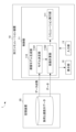
- FIG. 1 is a diagram illustrating an example of a functional block configuration of a processing simulation system according to an embodiment.
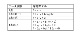
- FIG. 13 is a diagram illustrating an example of a relationship between the number of data points and the type of friction model.
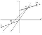
- FIG. 2B is a diagram showing an example of the relationship shown in FIG. 2A in a graph.
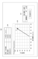
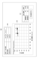
- FIG. 13 is a diagram showing an example of a screen when the number of data points is one.
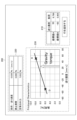
- FIG. 13 is a diagram showing an example of a screen when the number of data points is two (the same).
- FIG. 13 is a diagram showing an example of a screen when the number of data points is two (reverse).
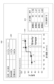
- FIG. 13 is a diagram showing an example of a screen in the case where the number of data points is four.
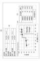
- FIG. 13 is a diagram showing an example of a screen in the case where the number of data points is five.
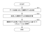
- 10 is a flowchart illustrating a simulation process of the machining simulation device.
- the type of friction model is determined according to the number of data points of torque and speed, coefficients in the friction model are calculated based on the determined type of friction model and the number of data points of torque and speed, and the generated friction model is reflected in the simulation execution unit.
- a friction model of a machine tool can be easily generated without test-running the machine tool and without specialized knowledge. The above is an outline of this embodiment.
- FIG. 1 is a diagram illustrating an example of a functional block configuration of a machining simulation system according to an embodiment.
- the machining simulation system 1 includes a machining simulation device 10 and a storage device 20 .
- the machining simulation device 10 and the storage device 20 are connected to each other and communicate with each other via a network (not shown) such as a LAN (Local Area Network) or the Internet.
- the machining simulation device 10 and the storage device 20 are provided with a communication unit (not shown) for communicating with each other via such a connection.
- the machining simulation device 10 and the storage device 20 may be directly connected to each other via a connection interface (not shown).
- the machining simulation device 10 and the storage device 20 are described as being different devices from each other, but as will be described later, the storage device 20 may be included in the machining simulation device 10 .
- the storage device 20 is a data server or the like, and stores data on the load and speed of a motor included in a machine tool (not shown) to be simulated. If the machine tool (not shown) has multiple motors, the storage device 20 may store the load and speed data for each motor.
- the load and speed data is, for example, data on the torque applied to the motor or the load torque measured by a torque sensor when the feed axis of the machine tool (not shown) to be controlled (simulated) is moving at a constant speed, and the moving speed of the feed axis. However, if the motor is a linear motor, the torque is interpreted as force.
- the machining simulation device 10 is a computer or the like well known to those skilled in the art, and includes a control unit 11, a display unit 12, and an input unit 13.
- the control unit 11 also includes a friction model generation unit 110 and a simulation execution unit 111.
- the friction model generation unit 110 also includes a model determination unit 1101 and a coefficient calculation unit 1102.
- the display unit 12 is, for example, a liquid crystal display. As described below, the display unit 12 displays a screen of the friction model generated by the friction model generation unit 110.
- the input unit 13 is, for example, a keyboard or a touch panel arranged on the display unit 12, and accepts input from the user.
- the control unit 11 has a CPU (Central Processing Unit), a ROM (Read Only Memory), a RAM (Random Access Memory), a CMOS (Complementary Metal-Oxide-Semiconductor) memory, etc., which are configured to be able to communicate with each other via a bus, and are well known to those skilled in the art.
- the CPU is a processor that controls the entire machining simulation device 10.
- the CPU reads out the system program and application program stored in the ROM via the bus, and controls the entire machining simulation device 10 according to the system program and application program.
- the control unit 11 is configured to realize the functions of a friction model generation unit 110 and a simulation execution unit 111.
- the friction model generation unit 110 is also configured to realize the functions of a model determination unit 1101 and a coefficient calculation unit 1102.
- the RAM stores various data such as temporary calculation data and display data.
- the CMOS memory is backed up by a battery (not shown), and is configured as a non-volatile memory that retains its stored state even when the power of the machining simulation device 10 is turned off.
- the friction model generation unit 110 acquires load and speed data, which are load (torque) values when the speed of the feed axis of a machine tool (not shown) is constant, from the storage device 20.
- the friction model generation unit 110 generates a friction model of the machine tool (not shown) based on the processing of the model determination unit 1101 and the coefficient calculation unit 1102 according to the acquired load and speed data and the number of data points, and reflects the generated friction model in the simulation execution unit 111.
- the model determination unit 1101 determines the type of friction model according to, for example, the number of data points of the load and speed data of a machine tool (not shown) acquired from the storage device 20 .
- Fig. 2A is a diagram showing an example of a relationship between the number of data points and the type of friction model
- Fig. 2B is a diagram showing an example of a graph representing the relationship in Fig. 2A.
- the friction model is a function that takes speed v as an input variable and outputs load f, and as the number of data points increases, the function becomes more complex, and the accuracy of reproducing friction increases.
- the friction model is a linear function of coefficient a shown by the dashed line, that is, the type of only viscous friction.
- the load f output by the friction model is "friction force" in a linear motion system and “friction torque” in a rotational system.
- the friction model is a linear function of coefficient a and intercept b ⁇ sgn(v) passing through the two data points shown by the dotted line, that is, a type that combines viscous friction and static friction.
- sgn(v) is a sign function of "1" if the speed v is positive and "-1" if it is negative.
- static friction is friction whose sign is determined according to the moving direction and whose magnitude does not depend on the speed.
- the friction model is a linear function of coefficient a and intercept g that passes through the data of the two points shown by the dashed dotted line, that is, a type that combines viscous friction and steady action. Note that intercept g is the steady action in a specific direction, that is, gravity.
- the model determination unit 1101 determines the type of friction model based on the number of data points of the load and speed data acquired from the storage device 20 (and, if the number of data points is two, the relationship in the direction of movement of the feed axis of the machine tool (not shown) between the two data points).
- the coefficient calculation unit 1102 calculates the coefficient a, intercept b ⁇ sgn(v), and intercept g in the friction model based on the load and speed data acquired from the storage device 20 and the type of the determined friction model. Specifically, for example, when the model determination unit 1101 determines the type of friction model having one data point, the coefficient calculation unit 1102 calculates f/v from the load and speed data of one point acquired from the storage device 20, and calculates the coefficient a.
- the friction model generation unit 110 displays the results related to the generated friction model on the display unit 12 in the form of a screen 200 shown in FIG. 3A. The screen 200 shown in FIG.
- 3A has a data display area 210 that displays the load and speed data acquired from the storage device 20, a coefficient display area 220 that displays the coefficient a calculated by the coefficient calculation unit 1102, and a model display area 230 that displays the generated friction model. That is, in the data display area 210, for example, a feed rate value of 50 mm/s and a load (TCMD) value of 9.799% are displayed as load and speed data for one point. Note that an "add row" button for adding load and speed data may be arranged in the data display area 210. In addition, in the coefficient display area 220, the value of load/feed rate, which is the coefficient a, 0.196%/(mm/s) is displayed.
- the coefficient calculation unit 1102 calculates the coefficient a and the intercept b ⁇ sgn(v) from the two load and speed data points from the storage device 20.
- the friction model generation unit 110 displays the results related to the generated friction model on the display unit 12 in the form of a screen 200 shown in FIG.
- the screen 200 shown in FIG. 3B displays, in the data display area 210, for example, feed rate values of 50 mm/s and 20 mm/s, and load values of 9.799% and 9.467%, as load and speed data for two points where the movement direction of the feed axis of a machine tool (not shown) is the same.
- the screen 200 displays the load/feed rate value 0.011%/(mm/s), which is the coefficient a, and the static friction (intercept b ⁇ sgn(v)) value 9.246%. Note that when the number of data points is two (the same), "0" is displayed because there is no steady external force (intercept g). In addition, the screen 200 displays the generated friction model in the model display area 230.
- the coefficient calculation unit 1102 calculates the coefficient a and intercept g from the two load and speed data points from the storage device 20.
- the friction model generation unit 110 displays the results related to the generated friction model on the display unit 12 in the form of a screen 200 shown in FIG.
- the screen 200 shown in FIG. 3C displays, in the data display area 210, for example, feed rate values of 50 mm/s and -50 mm/s, and load values of 9.799% and 5.905%, as load and speed data for two points where the movement direction of the feed axis of a machine tool (not shown) is opposite.
- the screen 200 displays the load/feed rate value 0.039%/(mm/s), which is the coefficient a, and the steady external force (intercept g) value 7.852%. Note that when the number of data points is two (opposite), there is no static friction (intercept b ⁇ sgn(v)), so it is displayed as "0". In addition, the screen 200 displays the generated friction model in the model display area 230.
- the coefficient calculation unit 1102 calculates the coefficients a1 , a2 and intercepts b1 , b2 from the four load and speed data from the storage device 20.
- the friction model generation unit 110 displays the results related to the generated friction model on the display unit 12 in the form of a screen 200 shown in FIG.
- the screen 200 displays, for example, feed rate values of 50 mm/s, 20 mm/s, -20 mm/s, -50 mm/s, and load values of 9.799%, 9.467%, 6.331%, and 5.905% as load and speed data at two points where the feed axis of a machine tool (not shown) moves in opposite directions.
- the screen 200 displays the generated friction model in the model display area 230.
- the coefficient calculation unit 1102 calculates coefficients a1 , a2 and intercepts b1 , b2 from the five load and speed data points acquired from the storage device 20. Specifically, as shown in Fig. 3E, for example, when the number of data points of the load and speed data is five, that is, when there are three data points on the positive side of the speed v, the coefficient calculation unit 1102 calculates the coefficient a1 and the intercept b1 by applying, for example, the least squares method to the load and speed data of the three points on the positive side of the speed v.
- N indicates the number of data points on the positive side of the speed v.
- ⁇ v> and ⁇ f> indicate the average value of the N speeds v and load f on the positive side.
- the coefficient calculation unit 1102 calculates the coefficient a2 and the intercept b2 for the load and speed data at two points on the negative side of the speed v, in the same manner as in the case of FIG. 3D.
- the friction model generation unit 110 displays the results of the generated friction model on the display unit 12 in the form of a screen 200 shown in Fig. 3E. Note that, although there are three load and speed data points on the positive side of the speed v in Fig. 3E, even if there are three or more load and speed data points on the negative side of the speed v, the coefficient calculation unit 1102 calculates the coefficient a2 and the intercept b2 in the same manner.
- 3E displays, for example, feedrate values of 50 mm/s, 35 mm/s, 20 mm/s, -20 mm/s, -50 mm/s, and load values of 9.799%, 9.807%, 9.467%, 6.331%, and 5.905% as load and speed data for five points of a feed axis of a machine tool (not shown) in a data display area 210.
- the screen 200 displays a load/feedrate value of 0.011%/(mm/s) and a static friction (intercept b 1 ) value of 9.304%, which are positive (plus side) coefficients a 1 , and a load/feedrate value of 0.014%/(mm/s) and a static friction (intercept b 2 ) value of 6.615%, which are negative (minus side) coefficients a 2. Furthermore, the screen 200 displays the generated friction model in a model display area 230 .
- the simulation execution unit 111 uses the friction model generated by the friction model generation unit 110 to simulate and reproduce the behavior of a machine tool (not shown). Specifically, the simulation execution unit 111 uses, for example, the friction model generated by the friction model generation unit 110 and a known simulation technique to simulate the position and behavior of each axis of a machine tool (not shown) using as input command positions of the axes generated based on the machining program. As a result, by using a friction model whose type and coefficient have been determined, the machining simulation device 10 can output a load in response to a speed input, and simulate and reproduce friction in the position and behavior of each axis of a machine tool (not shown).
- FIG. 4 is a flowchart illustrating the simulation process of the machining simulation device 10.
- step S11 the model determination unit 1101 determines a friction model according to the number of data points of the load and speed data of the machine tool (not shown) obtained from the storage device 20.
- step S12 based on the load and speed data obtained from the storage device 20 and the friction model determined in step S11, the coefficient a of the friction model (or coefficients a1 , a2 , intercepts b1 , b2 , intercepts b ⁇ sgn(v), intercept g) is calculated.
- step S13 the simulation execution unit 111 uses the friction model generated in step S12 to simulate the position and behavior of each axis of the machine tool (not shown) based on the machining program.
- the machining simulation device 10 can easily generate a friction model of a machine tool without test-running the machine tool and without expert knowledge. In other words, a user can take friction into account as a transmission characteristic of a machine tool without expert knowledge.
- the machining simulation device 10 is capable of generating a friction model with at least one piece of data, there is no need to test-run a machine tool (not shown) solely for the purpose of generating the friction model.
- the processing simulation device 10 and the storage device 20 are different devices, but the present invention is not limited to this.
- the storage device 20 may be configured to be included in the processing simulation device 10.
- the friction model in the case of four or more points is defined as shown in FIG. 2A, but is not limited thereto.
- each function included in the machining simulation device 10 can be realized by hardware, software, or a combination of these.
- being realized by software means being realized by a computer reading and executing a program.
- Non-transitory computer readable media include various types of tangible storage media. Examples of non-transitory computer readable media include magnetic recording media (e.g., flexible disks, magnetic tapes, hard disk drives), magneto-optical recording media (e.g., magneto-optical disks), CD-ROMs (Read Only Memory), CD-Rs, CD-R/Ws, and semiconductor memories (e.g., mask ROMs, PROMs (Programmable ROMs), EPROMs (Erasable PROMs), flash ROMs, RAMs).
- the program may also be provided to the computer by various types of temporary computer readable media. Examples of temporary computer readable media include electrical signals, optical signals, and electromagnetic waves.
- the temporary computer readable medium can provide the program to the computer via a wired communication path such as an electric wire or optical fiber, or via a wireless communication path.
- the step of writing the program to be recorded on the recording medium includes not only processes that are performed chronologically according to the order, but also processes that are not necessarily performed chronologically but are executed in parallel or individually.
- the step of writing the program may also be performed by cloud computing.
- the machining simulation device (10) includes a friction model generation unit (110) that generates a friction model of a machine tool, and a simulation execution unit (111) that simulates and reproduces the behavior of the machine tool using the friction model, and the friction model generation unit (110) includes a model determination unit (1101) that determines the type of friction model in accordance with the number of data points of torque and speed, and a coefficient calculation unit (1102) that calculates coefficients in the friction model based on the determined type of friction model and the number of data points of torque and speed, and the friction model generation unit (110) reflects the generated friction model in the simulation execution unit (111).
- the friction model includes a steady action in a specific direction.
- the model determination unit (1101) determines the type of friction model of viscous friction when the number of data points is one, determines the type of friction model of viscous friction and static friction when the number of data points is two and the speeds of the two points are moving in the same direction, determines the type of friction model of viscous friction and steady action when the number of data points is two and the speeds of the two points are moving in opposite directions, and determines the type of friction model of viscous friction, static friction, and steady action when the number of data points is four.
- the machining simulation method is a machining simulation method for causing a computer to function as a machining simulation device (10), and includes a friction model generation step of generating a friction model of a machine tool, and a simulation execution step of simulating and reproducing the behavior of the machine tool using the friction model.
- the friction model generation step includes a model determination step of determining a type of friction model in accordance with the number of data points of torque and speed, and a coefficient calculation step of calculating coefficients in the friction model based on the determined type of friction model and the number of data points of torque and speed, and the friction model generation step reflects the generated friction model in the simulation execution step.
- the friction model includes a steady action in a specific direction.
- the model determination step determines the type of friction model of viscous friction when the number of data points is one, determines the type of friction model of viscous friction and static friction when the number of data points is two and the speeds of the two points are moving in the same direction, determines the type of friction model of viscous friction and steady action when the number of data points is two and the speeds of the two points are moving in opposite directions, and determines the type of friction model of viscous friction, the static friction, and the steady action when the number of data points is four.
Landscapes
- Engineering & Computer Science (AREA)
- Physics & Mathematics (AREA)
- General Physics & Mathematics (AREA)
- Automation & Control Theory (AREA)
- Human Computer Interaction (AREA)
- Manufacturing & Machinery (AREA)
- Numerical Control (AREA)
Abstract
Description
また、機械の1以上の軸について、少なくとも位置指令及び位置フィードバックを取得し、取得した位置指令と位置フィードバックの差分である位置偏差に基づいて、位置制御を行う際の摩擦モデルの係数を推定し、摩擦を考慮した位置制御を行う制御装置の技術が知られている。例えば、特許文献2参照。
また、XYテーブルや産業用ロボット等の実機を制御して取得される摩擦力とモータ速度とに対して最小二乗法等を用いて直線近似して摩擦モデルを生成し、摩擦モデルから求まる摩擦力を補償値として、実機を精度良く制御する技術が知られている。例えば、特許文献3参照。
また、特許文献1-3に記載の技術では、摩擦モデルの生成には専門知識が必要で、場合によって摩擦モデルを生成するためだけの目的でもって工作機械を試運転する必要がある。
<一実施形態>
まず、本実施形態の概略を説明する。本実施形態では、トルクと速度のデータ点数に応じて摩擦モデルの種類を決定し、決定した摩擦モデルの種類、及びデータ点数のトルクと速度のデータに基づいて、摩擦モデルにおける係数を計算し、生成した前記摩擦モデルを前記シミュレーション実行部に反映させる。
これにより、本実施形態によれば、工作機械を試運転することなく、専門知識がなくても工作機械の摩擦モデルを容易に生成することができる。
以上が本実施形態の概略である。
図1に示すように、加工シミュレーションシステム1は、加工シミュレーション装置10、及び記憶装置20を有する。
加工シミュレーション装置10、及び記憶装置20は、LAN(Local Area Network)やインターネット等の図示しないネットワークを介して相互に接続されて通信を行っている。この場合、加工シミュレーション装置10、及び記憶装置20は、かかる接続によって相互に通信を行うための図示しない通信部を備えている。なお、加工シミュレーション装置10、及び記憶装置20は、図示しない接続インタフェースを介して互いに直接接続されてもよい。
また、加工シミュレーション装置10と、記憶装置20とは、互いに異なる装置としたが、後述するように、記憶装置20は、加工シミュレーション装置10に含まれてもよい。
また、負荷と速度のデータとは、例えば、制御対象(シミュレーション対象)の工作機械(図示しない)の送り軸が一定の速度にあるときのモータ印加トルクあるいはトルクセンサで計測した負荷トルクと、当該送り軸の移動速度とのデータである。ただし、モータがリニアモータの場合にはトルクは力と読み替える。
加工シミュレーション装置10は、当業者にとって周知のコンピュータ等であり、制御部11、表示部12、及び入力部13を有する。また、制御部11は、摩擦モデル生成部110、及びシミュレーション実行部111を有する。また、摩擦モデル生成部110は、モデル決定部1101、及び係数計算部1102を有する。
制御部11は、CPU(Central Processing Unit)、ROM(Read Only Memory)、RAM(Random Access Memory)、CMOS(Complementary Metal-Oxide-Semiconductor)メモリ等を有し、これらはバスを介して相互に通信可能に構成される、当業者にとって公知のものである。
CPUは加工シミュレーション装置10を全体的に制御するプロセッサである。CPUは、ROMに格納されたシステムプログラム及びアプリケーションプログラムを、バスを介して読み出し、システムプログラム及びアプリケーションプログラムに従って加工シミュレーション装置10全体を制御する。これにより、図1に示すように、制御部11が、摩擦モデル生成部110、及びシミュレーション実行部111の機能を実現するように構成される。また、摩擦モデル生成部110は、モデル決定部1101、及び係数計算部1102の機能を実現するように構成される。RAMには一時的な計算データや表示データ等の各種データが格納される。また、CMOSメモリは図示しないバッテリでバックアップされ、加工シミュレーション装置10の電源がオフされても記憶状態が保持される不揮発性メモリとして構成される。
なお、モデル決定部101の処理について説明するにあたり、データ点数と摩擦モデルの種類との関係について最初に説明する。
図2Aは、データ点数と摩擦モデルの種類との関係の一例を示す図である。図2Bは、図2Aの関係をグラフで表した一例を示す図である。
図2Aに示すように、摩擦モデルは、速度vを入力変数として負荷fを出力する関数であり、データ点数が増えるに従い複雑な関数となり、摩擦の再現精度が高まる。すなわち、図2Bに示すように、記憶装置20から取得した負荷と速度のデータのデータ点数が1点(例えば、負荷と速度のデータE1等)の場合、摩擦モデルは、破線で示す係数aの一次関数、すなわち粘性摩擦のみの種類となる。なお、摩擦モデルが出力する負荷fは、直動系では「摩擦力」、回転系では「摩擦トルク」となる。
また、記憶装置20から取得した負荷と速度のデータのデータ点数が、例えば工作機械(図示しない)の送り軸の移動方向が同じ負荷と速度のデータE1、E2等の2点(同一)の場合、摩擦モデルは、点線で示す当該2点のデータを通る係数a、切片b・sgn(v)の一次関数、すなわち粘性摩擦と静止摩擦とを合わせた種類となる。なお、sgn(v)は、速度vが正ならば「1」、負ならば「-1」の符号関数である。すなわち、静止摩擦は移動方向に応じて符号が決まり、大きさが速度に依存しない摩擦である。また、データ点数が2点(同一)の場合の摩擦モデルは、計算を安定化させるために速度v=0近傍において連続性をもたせるようにしてもよい。
また、記憶装置20から取得した負荷と速度のデータのデータ点数が、例えば工作機械(図示しない)の送り軸の移動方向が逆の関係の負荷と速度のデータE1、E3等の2点(逆)の場合、摩擦モデルは、一点鎖線で示す当該2点のデータを通る係数a、切片gの一次関数、すなわち粘性摩擦と定常的な作用とを合わせた種類となる。なお、切片gは、特定方向への定常的な作用、すなわち重力である。
また、記憶装置20から取得した負荷と速度のデータが、工作機械(図示しない)の送り軸の移動方向がプラス側及びマイナス側それぞれで2点以上、すなわち合計4点以上(例えば、負荷と速度のデータE1~E4等)の場合、摩擦モデルは、実線で示す速度vがプラス側で負荷f=a1・v+b1、マイナス側で負荷f=a2・v+b2、速度vが「0」のとき負荷f=(b1+b2)/2となる、粘性摩擦と静止摩擦と定常的な作用とを合わせた種類となる。
以上のことから、モデル決定部1101は、記憶装置20から取得する負荷と速度のデータのデータ点数(及びデータ点数が2点の場合、当該2点のデータ間における工作機械(図示しない)の送り軸の移動方向の関係)に基づいて、摩擦モデルの種類を決定する。
具体的には、係数計算部1102は、例えば、モデル決定部1101によりデータ点数が1点の摩擦モデルの種類が決定されると、記憶装置20から取得された1点の負荷と速度のデータからf/vを計算し、係数aを計算する。摩擦モデル生成部110は、生成された摩擦モデルに関する結果を、図3Aに示す画面200で表示部12に表示する。
図3Aに示す画面200は、記憶装置20から取得された負荷と速度のデータを表示するデータ表示領域210、係数計算部1102により計算された係数aを表示する係数表示領域220、及び生成された摩擦モデルを表示するモデル表示領域230を有する。すなわち、データ表示領域210では、1点の負荷と速度のデータとして、例えば、送り速度の値50mm/s、負荷(TCMD)の値9.799%それぞれが表示されている。なお、データ表示領域210には、負荷と速度のデータを追加する「行を追加する」ボタンが配置されてもよい。また、係数表示領域220では、係数aである負荷/送り速度の値0.196%/(mm/s)が表示されている。なお、データ点数が1点の場合、静止摩擦(切片b・sgn(v))及び定常の外力(切片g)がないことから「0」に表示されている。また、モデル表示領域230では、生成された摩擦モデルが表示されている。
図3Bに示す画面200は、データ表示領域210において、例えば、図示しない工作機械の送り軸の移動方向が同じ2点の負荷と速度のデータとして、送り速度の値50mm/sと20mm/s、及び負荷の値9.799%と9.467%それぞれを表示している。画面200は、係数表示領域220において、係数aである負荷/送り速度の値0.011%/(mm/s)、及び静止摩擦(切片b・sgn(v))の値9.246%を表示している。なお、データ点数が2点(同一)の場合、定常の外力(切片g)がないことから「0」に表示されている。また、画面200は、モデル表示領域230で、生成された摩擦モデルを表示している。
図3Cに示す画面200は、データ表示領域210において、例えば、図示しない工作機械の送り軸の移動方向が逆の2点の負荷と速度のデータとして、送り速度の値50mm/sと-50mm/s、及び負荷の値9.799%と5.905%それぞれを表示している。画面200は、係数表示領域220において、係数aである負荷/送り速度の値0.039%/(mm/s)、及び定常の外力(切片g)の値7.852%を表示している。なお、データ点数が2点(逆)の場合、静止摩擦(切片b・sgn(v))がないことから「0」に表示されている。また、画面200は、モデル表示領域230で、生成された摩擦モデルを表示している。
図3Dに示す画面200は、データ表示領域210において、例えば、図示しない工作機械の送り軸の移動方向が逆の2点の負荷と速度のデータとして、送り速度の値50mm/s、20mm/s、-20mm/s、-50mm/s、及び負荷の値9.799%、9.467%、6.331%、5.905%それぞれを表示している。画面200は、係数表示領域220において、係数a(=(a1+a2)/2)である負荷/送り速度の値0.013%/(mm/s)、静止摩擦(切片b・sgn(v))の値1.315%、及び定常の外力(負荷f=(b1+b2)/2)の値7.930%を表示している。また、画面200は、モデル表示領域230で、生成された摩擦モデルを表示している。
具体的には、図3Eに示すように、例えば、負荷と速度のデータのデータ点数が5点、すなわち速度vのプラス側にデータが3点ある場合、係数計算部1102は、速度vのプラス側の3点の負荷と速度のデータに対して、例えば最小二乗法等を適用して係数a1と切片b1とを計算する。すなわち、係数計算部1102は、係数a1=Σi=1,N(vi-<v>)・(fi-<f>)/Σi=1,N(vi-<v>)2、及び切片b1=<f>-a1・<v>を計算する。ここで、Nは、速度vのプラス側のデータ点数を示す。また、<v>、<f>は、プラス側のN個の速度v、及び負荷fの平均値を示す。
なお、係数計算部1102は、速度vのマイナス側に2点の負荷と速度のデータに対して、図3Dの場合と同様に、係数a2と切片b2とを計算する。
摩擦モデル生成部110は、生成された摩擦モデルに関する結果を、図3Eに示す画面200で表示部12に表示する。なお、図3Eでは、速度vのプラス側に3点の負荷と速度のデータがあったが、速度vのマイナス側に3点以上の負荷と速度のデータがある場合も、係数計算部1102は、同様に係数a2及び切片b2を計算する。
図3Eに示す画面200は、データ表示領域210において、例えば、図示しない工作機械の送り軸の5点の負荷と速度のデータとして、送り速度の値50mm/s、35mm/s、20mm/s、-20mm/s、-50mm/s、及び負荷の値9.799%、9.807%、9.467%、6.331%、5.905%それぞれを表示している。画面200は、係数表示領域220において、正方向(プラス側)の係数a1である負荷/送り速度の値0.011%/(mm/s)、静止摩擦(切片b1)の値9.304%と、負方向(マイナス側)の係数a2である負荷/送り速度の値0.014%/(mm/s)、静止摩擦(切片b2)の値6.615%とを表示している。また、画面200は、モデル表示領域230で、生成された摩擦モデルを表示している。
具体的には、シミュレーション実行部111は、例えば、摩擦モデル生成部110により生成された摩擦モデルと、公知のシミュレーションの手法とを用いて、加工プログラムに基づいて生成された軸の指令位置を入力として、図示しない工作機械の各軸の位置・挙動をシミュレーションする。
これにより、加工シミュレーション装置10は、種類と係数が決定された摩擦モデルを用いることで、速度入力に対して負荷を出力して、図示しない工作機械の各軸の位置・挙動における摩擦を模擬再現することが可能となる。
次に、図4を参照しながら、加工シミュレーション装置10のシミュレーション処理の流れを説明する。
図4は、加工シミュレーション装置10のシミュレーション処理について説明するフローチャートである。
また、加工シミュレーション装置10は、最低でも1点のデータがあれば摩擦モデルを生成することが可能であるため、摩擦モデルを生成するためだけの目的でもって工作機械(図示しない)を試運転する必要がない。
一実施形態では、加工シミュレーション装置10と、記憶装置20とは、互いに異なる装置としたが、これに限定されない。例えば、記憶装置20は、加工シミュレーション装置10に含まれる構成としてもよい。
また例えば、上述の実施形態では、4点以上の場合の摩擦モデルとして、図2Aに示すものを定義したが、これに限定されない。例えば、4点以上の場合の摩擦モデルとして、f=a・v+b・sgn(v)+gの粘性摩擦と静止摩擦と定常的な作用とからなる一次関数でもよい。この場合、係数a、切片b・sgn(v)、及び切片gは、図2Aに示す摩擦モデルの係数a1、a2、及び切片b1、b2を用いて、a=(a1+a2)/2、b=(b1-b2)/2、及びg=(b1+b2)/2と求めることができる。
(付記1)
加工シミュレーション装置(10)は、工作機械の摩擦モデルを生成する摩擦モデル生成部(110)と、摩擦モデルを使用して工作機械の挙動を模擬再現するシミュレーション実行部(111)と、を備え、摩擦モデル生成部(110)は、トルクと速度のデータ点数に応じて摩擦モデルの種類を決定するモデル決定部(1101)と、決定した摩擦モデルの種類、及びデータ点数のトルクと速度のデータに基づいて、摩擦モデルにおける係数を計算する係数計算部(1102)と、を含み、摩擦モデル生成部(110)は、生成した摩擦モデルをシミュレーション実行部(111)に反映させる。
(付記2)
付記1の加工シミュレーション装置(10)において、摩擦モデルは、特定方向への定常的な作用を含む。
(付記3)
付記2の加工シミュレーション装置(10)において、モデル決定部(1101)は、データ点数が1点の場合、粘性摩擦の摩擦モデルの種類を決定し、データ点数が2点で、2点の速度が同じ移動方向の場合、粘性摩擦と静止摩擦との摩擦モデルの種類を決定し、データ点数が2点で、2点の速度が互いに逆の移動方向の場合、粘性摩擦と定常的な作用との摩擦モデルの種類を決定し、データ点数が4点の場合、粘性摩擦と静止摩擦と定常的な作用との摩擦モデルの種類を決定する。
(付記4)
加工シミュレーション方法は、コンピュータを加工シミュレーション装置(10)として機能させるための加工シミュレーション方法であって、工作機械の摩擦モデルを生成する摩擦モデル生成ステップと、摩擦モデルを使用して工作機械の挙動を模擬再現するシミュレーション実行ステップと、を備え、摩擦モデル生成ステップは、トルクと速度のデータ点数に応じて摩擦モデルの種類を決定するモデル決定ステップと、決定した摩擦モデルの種類、及びデータ点数のトルクと速度のデータに基づいて、摩擦モデルにおける係数を計算する係数計算ステップと、を含み、摩擦モデル生成ステップは、生成した摩擦モデルをシミュレーション実行ステップに反映させる。
(付記5)
付記4の加工シミュレーション方法において、摩擦モデルは、特定方向への定常的な作用を含む。
(付記6)
付記5の加工シミュレーション方法において、モデル決定ステップは、データ点数が1点の場合、粘性摩擦の摩擦モデルの種類を決定し、データ点数が2点で、2点の速度が同じ移動方向の場合、粘性摩擦と静止摩擦との摩擦モデルの種類を決定し、データ点数が2点で、2点の速度が互いに逆の移動方向の場合、粘性摩擦と定常的な作用との摩擦モデルの種類を決定し、データ点数が4点の場合、粘性摩擦と前記静止摩擦と前記定常的な作用との摩擦モデルの種類を決定する。
10 加工シミュレーション装置
11 制御部
110 摩擦モデル生成部
1101 モデル決定部
1102 係数計算部
111 シミュレーション実行部
12 表示部
13 入力部
20 記憶装置
Claims (6)
- 工作機械の摩擦モデルを生成する摩擦モデル生成部と、
前記摩擦モデルを使用して前記工作機械の挙動を模擬再現するシミュレーション実行部と、を備え、
前記摩擦モデル生成部は、
トルクと速度のデータ点数に応じて前記摩擦モデルの種類を決定するモデル決定部と、
決定した前記摩擦モデルの種類、及び前記データ点数のトルクと速度のデータに基づいて、前記摩擦モデルにおける係数を計算する係数計算部と、を含み、
前記摩擦モデル生成部は、生成した前記摩擦モデルを前記シミュレーション実行部に反映させる、
加工シミュレーション装置。 - 前記摩擦モデルは、特定方向への定常的な作用を含む、請求項1に記載の加工シミュレーション装置。
- 前記モデル決定部は、前記データ点数が1点の場合、粘性摩擦の摩擦モデルの種類を決定し、前記データ点数が2点で、前記2点の速度が同じ移動方向の場合、前記粘性摩擦と静止摩擦との摩擦モデルの種類を決定し、前記データ点数が2点で、前記2点の速度が互いに逆の移動方向の場合、前記粘性摩擦と前記定常的な作用との摩擦モデルの種類を決定し、前記データ点数が4点の場合、前記粘性摩擦と前記静止摩擦と前記定常的な作用との摩擦モデルの種類を決定する、請求項2に記載の加工シミュレーション装置。
- コンピュータを加工シミュレーション装置として機能させるための加工シミュレーション方法であって、
工作機械の摩擦モデルを生成する摩擦モデル生成ステップと、
前記摩擦モデルを使用して前記工作機械の挙動を模擬再現するシミュレーション実行ステップと、を備え、
前記摩擦モデル生成ステップは、
トルクと速度のデータ点数に応じて前記摩擦モデルの種類を決定するモデル決定ステップと、
決定した前記摩擦モデルの種類、及び前記データ点数のトルクと速度のデータに基づいて、前記摩擦モデルにおける係数を計算する係数計算ステップと、を含み、
前記摩擦モデル生成ステップは、生成した前記摩擦モデルを前記シミュレーション実行ステップに反映させる、
加工シミュレーション方法。 - 前記摩擦モデルは、特定方向への定常的な作用を含む、請求項4に記載の加工シミュレーション方法。
- 前記モデル決定ステップは、前記データ点数が1点の場合、粘性摩擦の摩擦モデルの種類を決定し、前記データ点数が2点で、前記2点の速度が同じ移動方向の場合、前記粘性摩擦と静止摩擦との摩擦モデルの種類を決定し、前記データ点数が2点で、前記2点の速度が互いに逆の移動方向の場合、前記粘性摩擦と前記定常的な作用との摩擦モデルの種類を決定し、前記データ点数が4点の場合、前記粘性摩擦と前記静止摩擦と前記定常的な作用との摩擦モデルの種類を決定する、請求項5に記載の加工シミュレーション方法。
Priority Applications (5)
| Application Number | Priority Date | Filing Date | Title |
|---|---|---|---|
| DE112023001973.8T DE112023001973T5 (de) | 2023-04-07 | 2023-04-07 | Bearbeitungssimulationsvorrichtung und Bearbeitungssimulationsverfahren |
| US18/872,594 US20250164953A1 (en) | 2023-04-07 | 2023-04-07 | Machining simulation device and machining simulation method |
| CN202380049409.XA CN119422115B (zh) | 2023-04-07 | 2023-04-07 | 加工模拟装置以及加工模拟方法 |
| JP2023540634A JP7343735B1 (ja) | 2023-04-07 | 2023-04-07 | 加工シミュレーション装置及び加工シミュレーション方法 |
| PCT/JP2023/014420 WO2024209686A1 (ja) | 2023-04-07 | 2023-04-07 | 加工シミュレーション装置及び加工シミュレーション方法 |
Applications Claiming Priority (1)
| Application Number | Priority Date | Filing Date | Title |
|---|---|---|---|
| PCT/JP2023/014420 WO2024209686A1 (ja) | 2023-04-07 | 2023-04-07 | 加工シミュレーション装置及び加工シミュレーション方法 |
Publications (1)
| Publication Number | Publication Date |
|---|---|
| WO2024209686A1 true WO2024209686A1 (ja) | 2024-10-10 |
Family
ID=87934819
Family Applications (1)
| Application Number | Title | Priority Date | Filing Date |
|---|---|---|---|
| PCT/JP2023/014420 Ceased WO2024209686A1 (ja) | 2023-04-07 | 2023-04-07 | 加工シミュレーション装置及び加工シミュレーション方法 |
Country Status (5)
| Country | Link |
|---|---|
| US (1) | US20250164953A1 (ja) |
| JP (1) | JP7343735B1 (ja) |
| CN (1) | CN119422115B (ja) |
| DE (1) | DE112023001973T5 (ja) |
| WO (1) | WO2024209686A1 (ja) |
Cited By (1)
| Publication number | Priority date | Publication date | Assignee | Title |
|---|---|---|---|---|
| CN119422115A (zh) * | 2023-04-07 | 2025-02-11 | 发那科株式会社 | 加工模拟装置以及加工模拟方法 |
Citations (4)
| Publication number | Priority date | Publication date | Assignee | Title |
|---|---|---|---|---|
| JP2006146572A (ja) * | 2004-11-19 | 2006-06-08 | Yaskawa Electric Corp | サーボ制御装置および方法 |
| JP2022090463A (ja) * | 2020-12-07 | 2022-06-17 | 三菱電機株式会社 | モータ制御装置 |
| WO2022162740A1 (ja) * | 2021-01-26 | 2022-08-04 | 三菱電機株式会社 | 数値制御装置 |
| WO2022162944A1 (ja) * | 2021-02-01 | 2022-08-04 | 三菱電機株式会社 | シミュレーション装置、工作機械システム、シミュレーション方法および加工方法 |
Family Cites Families (11)
| Publication number | Priority date | Publication date | Assignee | Title |
|---|---|---|---|---|
| US3916279A (en) * | 1973-08-20 | 1975-10-28 | Hitachi Ltd | Friction compensating apparatus for load moving machines |
| JP2006121806A (ja) * | 2004-10-20 | 2006-05-11 | Yaskawa Electric Corp | モータ制御装置における摩擦補償方法およびモータ制御装置 |
| JP4602921B2 (ja) * | 2006-03-07 | 2010-12-22 | 株式会社日立産機システム | モータ制御装置およびモータ制御方法 |
| JP2009208115A (ja) * | 2008-03-04 | 2009-09-17 | Kobe Steel Ltd | 圧延制御パラメータの算出方法及び算出装置、圧延シミュレーション装置 |
| JP6051970B2 (ja) * | 2013-03-12 | 2016-12-27 | ブラザー工業株式会社 | 数値制御装置と摩擦補償方法 |
| JP5650814B1 (ja) * | 2013-07-05 | 2015-01-07 | ファナック株式会社 | フィードフォワード制御を備えたモータ制御装置 |
| CN107918276A (zh) * | 2017-11-13 | 2018-04-17 | 东南大学 | 一种机电作动系统摩擦副的精确建模方法 |
| JP2019152936A (ja) | 2018-02-28 | 2019-09-12 | ファナック株式会社 | 工作機械の加工シミュレーション装置 |
| JP6841852B2 (ja) | 2018-04-17 | 2021-03-10 | ファナック株式会社 | 制御装置及び制御方法 |
| DE102019002644A1 (de) * | 2018-04-17 | 2019-10-17 | Fanuc Corporation | Steuerung und Steuerverfahren |
| WO2024209686A1 (ja) * | 2023-04-07 | 2024-10-10 | ファナック株式会社 | 加工シミュレーション装置及び加工シミュレーション方法 |
-
2023
- 2023-04-07 WO PCT/JP2023/014420 patent/WO2024209686A1/ja not_active Ceased
- 2023-04-07 DE DE112023001973.8T patent/DE112023001973T5/de active Pending
- 2023-04-07 US US18/872,594 patent/US20250164953A1/en active Pending
- 2023-04-07 JP JP2023540634A patent/JP7343735B1/ja active Active
- 2023-04-07 CN CN202380049409.XA patent/CN119422115B/zh active Active
Patent Citations (4)
| Publication number | Priority date | Publication date | Assignee | Title |
|---|---|---|---|---|
| JP2006146572A (ja) * | 2004-11-19 | 2006-06-08 | Yaskawa Electric Corp | サーボ制御装置および方法 |
| JP2022090463A (ja) * | 2020-12-07 | 2022-06-17 | 三菱電機株式会社 | モータ制御装置 |
| WO2022162740A1 (ja) * | 2021-01-26 | 2022-08-04 | 三菱電機株式会社 | 数値制御装置 |
| WO2022162944A1 (ja) * | 2021-02-01 | 2022-08-04 | 三菱電機株式会社 | シミュレーション装置、工作機械システム、シミュレーション方法および加工方法 |
Cited By (2)
| Publication number | Priority date | Publication date | Assignee | Title |
|---|---|---|---|---|
| CN119422115A (zh) * | 2023-04-07 | 2025-02-11 | 发那科株式会社 | 加工模拟装置以及加工模拟方法 |
| CN119422115B (zh) * | 2023-04-07 | 2025-12-05 | 发那科株式会社 | 加工模拟装置以及加工模拟方法 |
Also Published As
| Publication number | Publication date |
|---|---|
| JP7343735B1 (ja) | 2023-09-12 |
| CN119422115A (zh) | 2025-02-11 |
| JPWO2024209686A1 (ja) | 2024-10-10 |
| CN119422115B (zh) | 2025-12-05 |
| DE112023001973T5 (de) | 2025-02-27 |
| US20250164953A1 (en) | 2025-05-22 |
Similar Documents
| Publication | Publication Date | Title |
|---|---|---|
| Sharifi et al. | Model reference adaptive impedance control in Cartesian coordinates for physical human–robot interaction | |
| WO2020009139A1 (ja) | 学習方法、学習装置、学習システム及びプログラム | |
| Le et al. | System identifications of a 2DOF pendulum controlled by QUBE-servo and its unwanted oscillation factors | |
| JPWO2014091840A1 (ja) | サーボ制御装置 | |
| Kamenar et al. | Nanometric positioning accuracy in the presence of presliding and sliding friction: Modelling, identification and compensation | |
| WO2024209686A1 (ja) | 加工シミュレーション装置及び加工シミュレーション方法 | |
| Dills et al. | A hybrid active-passive actuation and control approach for kinesthetic handheld haptics | |
| JP2025094957A (ja) | デジタル装置 | |
| EP4052865A1 (en) | Information processing apparatus, robot system, information processing method, program, and recording medium | |
| Wang et al. | Trajectory tracking control of XY table using sliding mode adaptive control based on fast double power reaching law | |
| JPWO2022034679A5 (ja) | 挙動学習装置、挙動学習方法、挙動推定装置、挙動推定方法、及びプログラム | |
| Pagilla et al. | Adaptive control of mechanical systems with time-varying parameters and disturbances | |
| Miura et al. | High-stiff motion reproduction using position-based motion-copying system with acceleration-based bilateral control | |
| Ali et al. | The effect of parameters variation on bilateral controller | |
| Yu et al. | Design and implementation of a robust switching control scheme for a class of constrained robot tasks | |
| CN114785233B (zh) | 基于Lugre摩擦模型的参数辨识装置及方法 | |
| CN112975986B (zh) | 基于径向基函数的机械臂点对点轨迹规划方法及装置 | |
| Kawai et al. | Load-side acceleration control based on load-side velocity disturbance observer for geared actuator | |
| JP7281629B2 (ja) | モータ駆動装置 | |
| CN116787424A (zh) | 一种基于标称控制项和不确定项的二自由度平面机械臂控制方法、系统及存储介质 | |
| JP7722027B2 (ja) | 制御装置、開発支援装置および開発支援プログラム | |
| US12558781B2 (en) | Automatic machine control device and automatic machine control method | |
| JP7832624B2 (ja) | 制御システム、制御方法及びプログラム | |
| Huang et al. | Novel dynamic modeling of feed drive system using subspace method | |
| Ahmad et al. | Evaluation of friction models for haptic devices |
Legal Events
| Date | Code | Title | Description |
|---|---|---|---|
| WWE | Wipo information: entry into national phase |
Ref document number: 2023540634 Country of ref document: JP |
|
| 121 | Ep: the epo has been informed by wipo that ep was designated in this application |
Ref document number: 23932096 Country of ref document: EP Kind code of ref document: A1 |
|
| WWE | Wipo information: entry into national phase |
Ref document number: 18872594 Country of ref document: US |
|
| WWE | Wipo information: entry into national phase |
Ref document number: 112023001973 Country of ref document: DE |
|
| WWE | Wipo information: entry into national phase |
Ref document number: 202380049409.X Country of ref document: CN |
|
| WWP | Wipo information: published in national office |
Ref document number: 202380049409.X Country of ref document: CN |
|
| WWP | Wipo information: published in national office |
Ref document number: 112023001973 Country of ref document: DE |
|
| WWP | Wipo information: published in national office |
Ref document number: 18872594 Country of ref document: US |
|
| 122 | Ep: pct application non-entry in european phase |
Ref document number: 23932096 Country of ref document: EP Kind code of ref document: A1 |