WO2024209587A1 - 駆動方法、光源ユニット、照明ユニット、露光装置、及び露光方法 - Google Patents
駆動方法、光源ユニット、照明ユニット、露光装置、及び露光方法 Download PDFInfo
- Publication number
- WO2024209587A1 WO2024209587A1 PCT/JP2023/014082 JP2023014082W WO2024209587A1 WO 2024209587 A1 WO2024209587 A1 WO 2024209587A1 JP 2023014082 W JP2023014082 W JP 2023014082W WO 2024209587 A1 WO2024209587 A1 WO 2024209587A1
- Authority
- WO
- WIPO (PCT)
- Prior art keywords
- light source
- current value
- light
- current
- source element
- Prior art date
- Legal status (The legal status is an assumption and is not a legal conclusion. Google has not performed a legal analysis and makes no representation as to the accuracy of the status listed.)
- Ceased
Links
Images



Classifications
-
- G—PHYSICS
- G03—PHOTOGRAPHY; CINEMATOGRAPHY; ANALOGOUS TECHNIQUES USING WAVES OTHER THAN OPTICAL WAVES; ELECTROGRAPHY; HOLOGRAPHY
- G03F—PHOTOMECHANICAL PRODUCTION OF TEXTURED OR PATTERNED SURFACES, e.g. FOR PRINTING, FOR PROCESSING OF SEMICONDUCTOR DEVICES; MATERIALS THEREFOR; ORIGINALS THEREFOR; APPARATUS SPECIALLY ADAPTED THEREFOR
- G03F7/00—Photomechanical, e.g. photolithographic, production of textured or patterned surfaces, e.g. printing surfaces; Materials therefor, e.g. comprising photoresists; Apparatus specially adapted therefor
- G03F7/70—Microphotolithographic exposure; Apparatus therefor
- G03F7/70483—Information management; Active and passive control; Testing; Wafer monitoring, e.g. pattern monitoring
- G03F7/7055—Exposure light control in all parts of the microlithographic apparatus, e.g. pulse length control or light interruption
- G03F7/70558—Dose control, i.e. achievement of a desired dose
-
- G—PHYSICS
- G03—PHOTOGRAPHY; CINEMATOGRAPHY; ANALOGOUS TECHNIQUES USING WAVES OTHER THAN OPTICAL WAVES; ELECTROGRAPHY; HOLOGRAPHY
- G03F—PHOTOMECHANICAL PRODUCTION OF TEXTURED OR PATTERNED SURFACES, e.g. FOR PRINTING, FOR PROCESSING OF SEMICONDUCTOR DEVICES; MATERIALS THEREFOR; ORIGINALS THEREFOR; APPARATUS SPECIALLY ADAPTED THEREFOR
- G03F7/00—Photomechanical, e.g. photolithographic, production of textured or patterned surfaces, e.g. printing surfaces; Materials therefor, e.g. comprising photoresists; Apparatus specially adapted therefor
- G03F7/20—Exposure; Apparatus therefor
-
- G—PHYSICS
- G03—PHOTOGRAPHY; CINEMATOGRAPHY; ANALOGOUS TECHNIQUES USING WAVES OTHER THAN OPTICAL WAVES; ELECTROGRAPHY; HOLOGRAPHY
- G03F—PHOTOMECHANICAL PRODUCTION OF TEXTURED OR PATTERNED SURFACES, e.g. FOR PRINTING, FOR PROCESSING OF SEMICONDUCTOR DEVICES; MATERIALS THEREFOR; ORIGINALS THEREFOR; APPARATUS SPECIALLY ADAPTED THEREFOR
- G03F7/00—Photomechanical, e.g. photolithographic, production of textured or patterned surfaces, e.g. printing surfaces; Materials therefor, e.g. comprising photoresists; Apparatus specially adapted therefor
- G03F7/70—Microphotolithographic exposure; Apparatus therefor
- G03F7/70008—Production of exposure light, i.e. light sources
- G03F7/7005—Production of exposure light, i.e. light sources by multiple sources, e.g. light-emitting diodes [LED] or light source arrays
-
- G—PHYSICS
- G03—PHOTOGRAPHY; CINEMATOGRAPHY; ANALOGOUS TECHNIQUES USING WAVES OTHER THAN OPTICAL WAVES; ELECTROGRAPHY; HOLOGRAPHY
- G03F—PHOTOMECHANICAL PRODUCTION OF TEXTURED OR PATTERNED SURFACES, e.g. FOR PRINTING, FOR PROCESSING OF SEMICONDUCTOR DEVICES; MATERIALS THEREFOR; ORIGINALS THEREFOR; APPARATUS SPECIALLY ADAPTED THEREFOR
- G03F7/00—Photomechanical, e.g. photolithographic, production of textured or patterned surfaces, e.g. printing surfaces; Materials therefor, e.g. comprising photoresists; Apparatus specially adapted therefor
- G03F7/70—Microphotolithographic exposure; Apparatus therefor
- G03F7/70058—Mask illumination systems
- G03F7/70075—Homogenization of illumination intensity in the mask plane by using an integrator, e.g. fly's eye lens, facet mirror or glass rod, by using a diffusing optical element or by beam deflection
-
- G—PHYSICS
- G03—PHOTOGRAPHY; CINEMATOGRAPHY; ANALOGOUS TECHNIQUES USING WAVES OTHER THAN OPTICAL WAVES; ELECTROGRAPHY; HOLOGRAPHY
- G03F—PHOTOMECHANICAL PRODUCTION OF TEXTURED OR PATTERNED SURFACES, e.g. FOR PRINTING, FOR PROCESSING OF SEMICONDUCTOR DEVICES; MATERIALS THEREFOR; ORIGINALS THEREFOR; APPARATUS SPECIALLY ADAPTED THEREFOR
- G03F7/00—Photomechanical, e.g. photolithographic, production of textured or patterned surfaces, e.g. printing surfaces; Materials therefor, e.g. comprising photoresists; Apparatus specially adapted therefor
- G03F7/70—Microphotolithographic exposure; Apparatus therefor
- G03F7/708—Construction of apparatus, e.g. environment aspects, hygiene aspects or materials
- G03F7/70858—Environment aspects, e.g. pressure of beam-path gas, temperature
- G03F7/70883—Environment aspects, e.g. pressure of beam-path gas, temperature of optical system
- G03F7/70891—Temperature
-
- H—ELECTRICITY
- H05—ELECTRIC TECHNIQUES NOT OTHERWISE PROVIDED FOR
- H05B—ELECTRIC HEATING; ELECTRIC LIGHT SOURCES NOT OTHERWISE PROVIDED FOR; CIRCUIT ARRANGEMENTS FOR ELECTRIC LIGHT SOURCES, IN GENERAL
- H05B45/00—Circuit arrangements for operating light-emitting diodes [LED]
- H05B45/10—Controlling the intensity of the light
- H05B45/18—Controlling the intensity of the light using temperature feedback
-
- H—ELECTRICITY
- H10—SEMICONDUCTOR DEVICES; ELECTRIC SOLID-STATE DEVICES NOT OTHERWISE PROVIDED FOR
- H10H—INORGANIC LIGHT-EMITTING SEMICONDUCTOR DEVICES HAVING POTENTIAL BARRIERS
- H10H29/00—Integrated devices, or assemblies of multiple devices, comprising at least one light-emitting semiconductor element covered by group H10H20/00
- H10H29/80—Constructional details
- H10H29/85—Packages
- H10H29/858—Means for heat extraction or cooling
- H10H29/8582—Means for heat extraction or cooling characterised by their shape
-
- H—ELECTRICITY
- H10—SEMICONDUCTOR DEVICES; ELECTRIC SOLID-STATE DEVICES NOT OTHERWISE PROVIDED FOR
- H10H—INORGANIC LIGHT-EMITTING SEMICONDUCTOR DEVICES HAVING POTENTIAL BARRIERS
- H10H29/00—Integrated devices, or assemblies of multiple devices, comprising at least one light-emitting semiconductor element covered by group H10H20/00
- H10H29/80—Constructional details
- H10H29/85—Packages
- H10H29/858—Means for heat extraction or cooling
- H10H29/8586—Means for heat extraction or cooling comprising fluids, e.g. heat-pipes
Definitions
- Liquid crystal display panels have come into widespread use as display elements for personal computers, televisions, and the like.
- Liquid crystal display panels are manufactured by forming a circuit pattern of thin-film transistors on a plate (glass substrate) using photolithography techniques.
- An exposure device is used for this photolithography process, which projects and exposes an original pattern formed on a mask onto a photoresist layer on the plate via a projection optical system (for example, Patent Document 1).
- a method for driving a light source element is a method for driving a light source element that emits light at a first light emission amount when a current of a first current value is supplied when the temperature of the light source element is within a first temperature range, and includes starting a current supply to the light source element at a second current value lower than the first current value when the light source element is to be brought into a state in which it emits light at the first light emission amount, and increasing the current value of the current supplied to the light source element from the second current value to the first current value.
- the light source unit includes a plurality of light source elements that are two-dimensionally arranged on the surface of a fixed object and each emits light at a first light emission amount when a current of a first current value is supplied to the light source elements when the temperature of each element is within a first temperature range, and a control unit that controls the value of the current supplied to the light source elements, and when the control unit is to bring the light source elements into a state in which they emit light at the first light emission amount, the control unit starts supplying current to the light source elements at a second current value lower than the first current value, and increases the current value of the current supplied to the light source elements from the second current value to the first current value.
- the lighting unit includes the light source unit and a lighting optical system that guides the light emitted from the light source unit to the object to be illuminated.
- the exposure apparatus includes the above-mentioned illumination unit and a projection optical system that projects a pattern image of a mask illuminated by the illumination unit onto a photosensitive substrate.
- an exposure method is an exposure method using the above-mentioned exposure apparatus, and includes illuminating a mask with the illumination unit, and projecting a pattern image of the mask onto a photosensitive substrate using the projection optical system.
- a method for driving a light source element is a method for driving a light source element that emits light at a first light amount when a current of a first current value is supplied, and includes supplying a current to the light source element at a second current value lower than the first current value when the light source element is put into a state in which it emits light at the first light amount, and increasing the current value of the current supplied to the light source element from the second current value to the first current value.
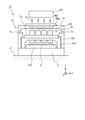
- FIG. 1 is a schematic diagram showing the configuration of an exposure apparatus according to an embodiment.
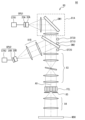
- FIG. 2 is a schematic diagram showing the configuration of the lighting unit according to the present embodiment.
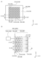
- FIG. 3A is a plan view that shows a schematic configuration of the first and second light source arrays
- FIG. 3B is a view that shows a schematic internal configuration of the first and second light source units.
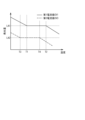
- FIG. 4 is a diagram illustrating the relationship between the temperature of the LED chip and the amount of light emitted.
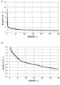
- FIG. 5(A) is a graph showing the measurement results of the light emission amount of the light-emitting portion of the LED chip in Comparative Example 1
- FIG. 5(B) is a graph in which the light emission amount deviation rate is enlarged from FIG.
- FIG. 5(A) in the range of 0% to 2%.
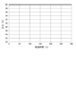
- FIG. 6 is a diagram showing the output versus elapsed time in the first comparative example.
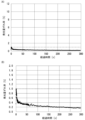
- FIG. 7(A) is a graph showing the measurement results of the light emission amount of the light-emitting portion of the LED chip in this embodiment, and
- FIG. 7(B) is a graph in which the light emission amount deviation rate is enlarged from FIG. 7(A) in the range of 0% to 2%.
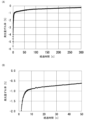
- FIG. 8(A) is a graph showing the output of the first control unit versus elapsed time in this embodiment, and
- FIG. 8(B) is a graph in which the range of output from 98% to 100% in FIG. 8(A) is enlarged.
- FIG. 9(A) is a graph showing the simulation results of the amount of light emitted by the light-emitting portion of the LED chip in Comparative Example 2
- FIG. 9(B) is an enlarged view of FIG. 9(A) for the range in which the deviation rate of the amount of light emitted is from -2% to 0% and the elapsed time is from 0 seconds to 50 seconds.
- FIG. 10 is a diagram showing the output versus elapsed time in Comparative Example 2.
- FIG. 11(A) is a graph showing the results of a simulation of the amount of light emitted by the light-emitting portion of the LED chip in this embodiment, and FIG.
- FIG. 11(B) is an enlarged view of the range in which the deviation rate of the amount of light emitted is from -2% to 0% and the elapsed time is from 0 seconds to 50 seconds.
- FIG. 12 is a diagram showing the output of the first control unit with respect to elapsed time in this embodiment.
- FIG. 13 is a schematic diagram showing a configuration of an illumination unit according to the first modification.
- FIG. 14A is a plan view showing an example of a heat sink according to Modification 2
- FIG. 14B is a plan view showing a state in which a first light source array is mounted on the heat sink.
- the exposure device 10 according to one embodiment will be described with reference to Figures 1 to 12.
- FIG. 1 is a diagram showing a schematic configuration of an exposure apparatus 10 according to the present embodiment.
- the exposure apparatus 10 is a scanning stepper (scanner) that transfers a pattern formed on the mask MSK onto a glass substrate (hereafter referred to as "plate") P by driving the mask MSK and the glass substrate P in the same direction and at the same speed relative to the projection optical system PL.
- the plate P is a rectangular glass substrate used, for example, in liquid crystal display devices (flat panel displays), with at least one side or diagonal length of 500 mm or more.
- the direction in which the mask MSK and plate P are driven during scanning exposure is defined as the X-axis direction
- the direction perpendicular to this in the horizontal plane is defined as the Y-axis direction
- the direction perpendicular to the X-axis and Y-axis is defined as the Z-axis direction
- the directions of rotation (tilt) around the X-axis, Y-axis, and Z-axis are defined as the ⁇ x, ⁇ y, and ⁇ z directions, respectively.
- the exposure apparatus 10 includes an illumination system IOP, a mask stage MST that holds a mask MSK, a projection optical system PL, a body 70 that supports these, a substrate stage PST that holds a plate P, and a control system for these.
- the control system provides overall control of each component of the exposure apparatus 10.
- the body 70 comprises a base (vibration isolation table) 71, columns 72A and 72B, an optical base 73, a support 74, and a slide guide 75.
- the base (vibration isolation table) 71 is placed on a floor F and supports the columns 72A, 72B, etc. by isolating vibrations from the floor F.
- the columns 72A and 72B each have a frame shape, and the column 72A is placed inside the column 72B.
- the optical base 73 has a flat plate shape and is fixed to the ceiling of the column 72A.
- the support 74 is supported by the ceiling of the column 72B via a slide guide 75.
- the slide guide 75 comprises an air ball lifter and a positioning mechanism, and positions the support 74 (i.e., the mask stage MST described later) at an appropriate position in the X-axis direction relative to the optical base 73.
- the illumination system IOP is disposed above the body 70.
- the illumination system IOP irradiates the mask MSK with illumination light IL.
- the detailed configuration of the illumination system IOP will be described later.
- the mask stage MST is supported by a support 74.
- a mask MSK having a pattern surface (the lower surface in FIG. 1) on which a circuit pattern is formed is fixed to the mask stage MST by, for example, vacuum adsorption (or electrostatic adsorption).
- the mask stage MST is driven by a drive system including, for example, a linear motor at a predetermined stroke in the scanning direction (X-axis direction) and is also slightly driven in the non-scanning directions (Y-axis direction and ⁇ z direction).
- the position information of the mask stage MST in the XY plane is measured by an interferometer system.
- the interferometer system measures the position of the mask stage MST by irradiating a measurement beam onto a movable mirror (or a mirror-finished reflective surface (not shown)) provided at the end of the mask stage MST and receiving the reflected light from the movable mirror.
- the measurement results are supplied to a control device (not shown), which drives the mask stage MST via a drive system in accordance with the measurement results of the interferometer system.
- the projection optical system PL is supported by the optical base 73 below (-Z side) the mask stage MST.
- the projection optical system PL is configured in the same manner as the projection optical system disclosed in, for example, US Pat. No. 5,729,331, and includes a plurality of (for example, seven) projection optical units 100 (multi-lens projection optical units) arranged in a staggered pattern, for example, to form a rectangular image field with the Y-axis direction as the longitudinal direction.
- four projection optical units 100 are arranged at a predetermined interval in the Y-axis direction, and the remaining three projection optical units 100 are arranged at a predetermined interval in the Y-axis direction, spaced apart from the four projection optical units 100 on the +X side.
- each of the multiple projection optical units 100 for example, a system that forms an erect normal image with a two-sided telecentric equal magnification system is used.
- the multiple projection areas of the projection optical units 100 arranged in a staggered pattern are collectively called the exposure area.
- the illumination light IL that has passed through the mask MSK forms a projected image (partial upright image) of the circuit pattern of the mask MSK in the illumination area in the irradiation area (exposure area (conjugate to the illumination area)) on the plate P arranged on the image plane side of the projection optical system PL via the projection optical system PL.
- a resist sensitizer
- the mask stage MST and the substrate stage PST By synchronously driving the mask stage MST and the substrate stage PST, i.e., by driving the mask MSK in the scanning direction (X-axis direction) relative to the illumination area (illumination light IL) and driving the plate P in the same scanning direction relative to the exposure area (illumination light IL), the plate P is exposed and the pattern of the mask MSK is transferred onto the plate P.
- the substrate stage PST is placed on a base (vibration isolation table) 71 below (on the -Z side) the projection optical system PL.
- a plate P is held on the substrate stage PST via a substrate holder (not shown).
- the position information of the substrate stage PST in the XY plane (including rotation information (yawing amount (amount of rotation in the ⁇ z direction ⁇ z), pitching amount (amount of rotation in the ⁇ x direction ⁇ x), and rolling amount (amount of rotation in the ⁇ y direction ⁇ y))) is measured by an interferometer system.
- the interferometer system measures the position of the substrate stage PST by irradiating a measurement beam from the optical base 73 to a movable mirror (or a mirror-finished reflective surface (not shown)) provided at the end of the substrate stage PST and receiving the reflected light from the movable mirror.
- the measurement result is supplied to a control device (not shown), which drives the substrate stage PST in accordance with the measurement result of the interferometer system.
- alignment measurement (e.g., EGA, etc.) is performed prior to exposure, and the plate P is exposed using the results in the following procedure.
- the mask stage MST and substrate stage PST are synchronously driven in the X-axis direction according to instructions from the control device. This performs scanning exposure on the first shot area on the plate P.
- the control device moves (steps) the substrate stage PST to a position corresponding to the second shot area. Then, scanning exposure is performed on the second shot area.
- the control device similarly repeats stepping between the shot areas of the plate P and scanning exposure on the shot areas to transfer the pattern of the mask MSK to all shot areas on the plate P.
- the illumination system IOP includes a plurality of illumination units 90 corresponding to the respective projection optical units 100 included in the projection optical system PL.
- FIG. 2 is a diagram showing a schematic configuration of the illumination unit 90.
- the illumination unit 90 includes a first light source unit OPU1, a second light source unit OPU2, and an illumination optical system 80.
- the first light source unit OPU1 includes a first light source array 20A, a first magnifying optical system 30A, and a first control unit CTR1
- the second light source unit OPU2 includes a second light source array 20B, a second magnifying optical system 30B, and a second control unit CTR2.
- FIG. 3(A) is a plan view showing the schematic configuration of the first light source array 20A and the second light source array 20B.
- the first light source array 20A includes a plurality of LED (Light Emitting Diode) chips 23A (5 ⁇ 5 in FIG. 3(A)) arranged on a substrate 21A, for example.
- the number of LED chips 23A may be changed as necessary.
- Each of the plurality of LED chips 23A has a light emitting portion 231A, and the peak wavelength of the light emitted from the light emitting portion 231A is in the range of 380 to 390 nm. In other words, the light emitting portion 231A is an ultraviolet LED (UV LED).
- UV LED ultraviolet LED
- the peak wavelength of the light emitted from the light emitting portion 231A is 385 nm.
- the light emitting surface of the light emitting portion 231A is a square, and the length of one side is a1.
- the LED chips 23A are arranged at a pitch P1.
- the pitch P1 is the distance between the centers of adjacent LED chips 23A.
- the second light source array 20B includes, for example, a plurality of LED chips 23B (5 x 5 in FIG. 3A) arranged on a substrate 21B.
- the number of LED chips 23B may be changed as necessary.
- Each of the plurality of LED chips 23B has a light-emitting portion 231B, and the peak wavelength of the light emitted from the light-emitting portion 231B is in the range of 360 to 370 nm.
- the light-emitting portion 231B is a UV LED. It is more preferable that the peak wavelength of the light emitted from the light-emitting portion 231B is 365 nm.
- the light-emitting surface of the light-emitting portion 231B is a square, and the length of one side is a2.
- the LED chips 23B are arranged at a pitch P2.
- the arrangement pitch P1 of the LED chips 23A and the arrangement pitch P2 of the LED chips 23B may be the same or different. Furthermore, the length a1 of one side of the light-emitting surface of the light-emitting portion 231A and the length a2 of one side of the light-emitting surface of the light-emitting portion 231B may be the same or different.
- the LED chips 23A and 23B may be arranged not on a substrate but on, for example, a heat sink.
- FIG. 3(B) is a diagram showing a schematic internal configuration of the first light source unit OPU1 and the second light source unit OPU2. Since the internal configurations of the first light source unit OPU1 and the second light source unit OPU2 are the same, the configuration of the first light source unit OPU1 will be mainly described here.
- the two directions in which the LED chips 23A are arranged are the X1 direction and the Y1 direction.
- the X1 direction and the Y1 direction are perpendicular to each other.
- the direction perpendicular to the X1 direction and the Y1 direction is the Z1 direction.
- the Z1 direction is approximately parallel to the optical axis OA of the light emitted by the light-emitting portion 231A.
- FIG. 3(B) in order to clarify the drawing, only four LED chips 23A arranged in a row along the Y1 direction are shown.
- the first magnifying optical system 30A is an optical system for forming a magnified image of the light-emitting portion 231A of each LED chip 23A on a predetermined plane PP.
- the first magnifying optical system 30A has a plurality of lens portions 31A arranged to correspond to the arrangement of the LED chips 23A.
- Each lens portion 31A is a double-telecentric optical system that enlarges and projects the light-emitting portion 231A at a magnification M1 that is equal to or greater than (arrangement pitch P1 of the LED chips 23B)/(length a1 of one side of the light-emitting surface of the light-emitting portion 231A).
- the second magnifying optical system 30B is a magnifying optical system for forming a magnified image of the light-emitting portion 231B of each LED chip 23B on a predetermined plane PP.
- the second magnifying optical system 30B has a plurality of lens portions 31B arranged to correspond to the arrangement of the LED chips 23B.
- Each lens portion 31B is a double-telecentric optical system that enlarges and projects the light-emitting portion 231B at a magnification M2 that is equal to or greater than (arrangement pitch P2 of the LED chips 23A)/(length a2 of one side of the light-emitting surface of the light-emitting portion 231B).
- each of the lens units 31A and 31B has four plano-convex lenses, but this is not limited to this, and the lens units 31A and 31B may have, for example, two biconvex lenses or three biconvex lenses. Furthermore, the lens units 31A and 31B may have, for example, a plano-convex lens and a biconvex lens.
- the first control unit CTR1 controls the current value of the current supplied to the LED chip 23A included in the first light source array 20A.
- the second control unit CTR2 controls the current value of the current supplied to the LED chip 23B included in the second light source array 20B.
- FIG. 4 is a diagram illustrating the relationship between the temperature of the LED chips 23A and 23B and the amount of light emitted by the light-emitting portions 231A and 231B.
- the first temperature range is, for example, 20°C to 90°C, and may be 20°C to 50°C.
- the light-emitting portions 231A and 231B of the LED chips 23A and 23B emit light with a second amount of light emitted LA2 when a current of a third current value CV3 lower than the first current value CV1 is supplied thereto.
- Temperature T3 is lower than temperature T1
- temperature T4 is lower than temperature T2.
- the first control unit CTR1 starts supplying current to the LED chip 23A at the second current value CV2 lower than the first current value CV1.
- the second control unit CTR2 starts supplying current to the LED chip 23B at the second current value CV2 lower than the first current value CV1.
- Fig. 5(A) is a graph showing the measurement results of the amount of light emitted by the light-emitting portion 231A of the LED chip 23A in Comparative Example 1.
- the vertical axis shows the deviation rate of the amount of light emitted
- the horizontal axis shows the elapsed time from the start of the current supply.
- Fig. 5(B) is a graph in Fig. 5(A) where the deviation rate of the amount of light emitted on the vertical axis is enlarged to a range of 0% to 2%.
- Figure 6 is a diagram showing the output versus elapsed time in Comparative Example 1.
- the output is constant at 100% from the start of current supply.
- current is supplied to the LED chip 23A at the first current value CV1 from the start of current supply.
- the light emitting portion 231A of the LED chip 23A emits light at an amount of light higher than the first amount of light emission LA1, and the amount of light emission decreases over time. This is because the amount of light emitted by the light emitting portion 231A of the LED chip 23A decreases as the temperature of the LED chip 23A increases. More specifically, when current supply to the LED chip 23A starts, the temperature of the LED chip 23A is low, so the amount of light emitted by the light emitting portion 231A of the LED chip 23A is high. Thereafter, the amount of light emitted decreases as the temperature of the LED chip 23A increases.
- the deviation rate of the light emission amount falls within the range of ⁇ 1%, and the light emission amount of the light-emitting portion 231A of the LED chip 23A stabilizes.
- FIG. 7(A) is a graph showing the measurement results of the amount of light emitted from the light-emitting portion 231A of the LED chip 23A in this embodiment
- FIG. 7(B) is a graph in which the range of the light emission amount deviation rate on the vertical axis in FIG. 7(A) is enlarged from 0% to 2%.
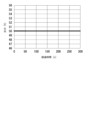
- FIG. 8(A) is a diagram showing the output of the first control unit CTR1 versus elapsed time in this embodiment
- FIG. 8(B) is a graph in which the range of output on the vertical axis in FIG. 8(A) is enlarged from 98% to 100%.
- the first control unit CTR1 starts current supply at an output lower than 100%, and increases the output over time. That is, it starts current supply to the LED chip 23A at a second current value CV2 lower than the first current value CV1 (in FIG. 8(A), a current value that is approximately 89% of the first current value CV1), and increases the current value of the current supplied to the LED chip 23A over time.
- the deviation rate of the light emission amount is within a range of ⁇ 1% from the start of the current supply.
- the LED chip 23A emits light at the first light emission amount LA1.
- the first light emission amount LA1 can be obtained at a current value lower than the first current value CV1, and it is believed that a current of an appropriate current value for obtaining the first light emission amount LA1 at each temperature can be supplied to the LED chip 23A by increasing the current value in response to the temperature rise of the LED chip 23A.
- the LED chip 23A continues to emit light at the first light emission amount LA1.
- How to increase the output (the current value of the current supplied to the LED chip 23A) can be determined from the change in the light emission deviation rate ( Figures 5(A) and 5(B)) obtained when current supply to the LED chip 23A begins at the first current value CV1.
- the gradient of the light emission amount deviation rate between elapsed time t1 and elapsed time t2 is calculated from the light emission amount deviation rate at elapsed time t1 and the light emission amount deviation rate at elapsed time t2, and the increase rate (increase amount) of the output between elapsed time t1 and elapsed time t2 can be determined based on the gradient.
- the output may be increased at a constant rate based on the value obtained by dividing the amount of change in the light emission amount deviation rate by the time from the start of current supply until the light emission amount deviation rate falls within the range of ⁇ 1% (average gradient of the light emission amount deviation rate).
- the gradient of the light emission amount deviation rate at adjacent measurement times is calculated, and the increase rate of the output is determined from the gradient of the light emission amount deviation rate. Therefore, the shape of the output graphs shown in FIG. 8(A) and FIG. 8(B) is a shape that is the shape of the light emission amount deviation rate graphs shown in FIG. 5(A) and FIG. 5(B) upside down.
- the first control unit CTR1 may further correct the output based on the light emission deviation rate (see FIG. 7A) achieved by changing the output as shown in FIG. 8A, for example.
- the light emission deviation rate shown in FIG. 7A may be reflected in the output shown in FIG. 8A to create a new output graph, and the first control unit CTR1 may change the output based on the new output graph. This can further shorten the time until the light emission amount of the light-emitting unit 231A of the LED chip 23A stabilizes.
- the correction of the output based on the light emission deviation rate may be performed multiple times.
- the first control unit CTR1 may also perform machine learning using the light emission deviation rate data and the output data as teacher data, and determine the output using the obtained trained model.
- the light emitting portion 231A of the LED chip 23A emits light with a second light emission amount LA2 when a current of a third current value CV3 lower than the first current value CV1 is supplied (see FIG. 4).
- the first control unit CTR1 reduces the current value of the current supplied to the LED chip 23A from the first current value CV1 to the third current value CV3. More specifically, the current value of the current supplied to the LED chip 23A is reduced over time from the first current value CV1 to the third current value CV3. This reduces the time until the light-emitting unit 231A of the LED chip 23A stably emits light at the second light emission amount LA2. This point will be described.
- Figure 9(A) is a graph showing the results of a simulation of the amount of light emitted by the light-emitting portion 231A of the LED chip 23A in Comparative Example 2.
- Figure 9(B) is an enlarged view of Figure 9(A) for the range in which the deviation rate of the amount of light emitted is -2% to 0% and the elapsed time is 0 seconds to 50 seconds.
- the vertical axis indicates the light emission amount deviation rate
- the horizontal axis indicates the elapsed time from when control was started to change the light emission amount of the light-emitting portion 231A of the LED chip 23A from the first light emission amount LA1 to the second light emission amount LA2.
- FIG. 10 is a diagram showing the output versus time in Comparative Example 2. It is assumed that the third current value CV3 is 50% of the first current value CV1. Therefore, an output of 50% means that the current value of the current supplied to the LED chip 23A is the third current value CV3. As shown in FIG. 9(B), in Comparative Example 2, the output versus time is constant at 50%. That is, in Comparative Example 2, a current is supplied to the LED chip 23A at the third current value CV3 immediately after control is started to change the light emission amount of the light-emitting portion 231A of the LED chip 23A from the first light emission amount LA1 to the second light emission amount LA2.
- the light emitting portion 231A of the LED chip 23A emits light at an amount lower than the second light emission amount LA2, and the amount of light emitted increases over time. This is because when the supply of current to the LED chip 23A at the third current value CV3 begins, the temperature of the LED chip 23A is higher than temperature T4, and so the amount of light emitted by the light emitting portion 231A of the LED chip 23A decreases. Thereafter, as the temperature of the LED chip 23A decreases, the amount of light emitted increases.
- the light emission amount deviation rate falls within the range of ⁇ 1%, and the light emission amount of the light-emitting portion 231A of the LED chip 23A stabilizes.
- FIG. 11(A) is a graph showing the results of a simulation of the amount of light emitted by the light-emitting portion 231A of the LED chip 23A in this embodiment
- FIG. 11(B) is an enlarged view of the range in which the deviation rate of the amount of light emitted is -2% to 0% and the elapsed time is 0 seconds to 50 seconds.
- FIG. 12 shows the output of the first control unit CTR1 versus elapsed time in this embodiment.
- the first control unit CTR1 when the first control unit CTR1 starts to control the light emission amount of the light-emitting unit 231A of the LED chip 23A from the first light emission amount LA1 to the second light emission amount LA2, it sets the current value of the current supplied to the LED chip 23A to a current value lower than the first current value CV1 and higher than the third current value CV3, and reduces the current value of the current supplied to the LED chip 23A over time to the third current value CV3.
- the first control unit CTR1 sets the current value 1/10th of a second after starting control to change the light emission amount of the light-emitting unit 231A of the LED chip 23A from the first light emission amount LA1 to the second light emission amount LA2 to about 56% of the first current value CV1, and sets the current value 2/10th of a second after starting control to change the light emission amount of the light-emitting unit 231A of the LED chip 23A from the first light emission amount LA1 to the second light emission amount LA2, and supplies a current to the LED chip 23A at a current value lower than the first current value CV1 and higher than the third current value CV3, and reduces the current value over time.
- the light emission amount deviation rate is within the range of ⁇ 1% from the start of control to change the light emission amount of the light-emitting portion 231A of the LED chip 23A from the first light emission amount LA1 to the second light emission amount LA2.
- the second light emission amount LA2 is obtained with a current value higher than the third current value CV3, and it is believed that by reducing the current value in response to the drop in temperature of the LED chip 23A, a current of an appropriate current value can be supplied to the LED chip 23A to obtain the second light emission amount LA2 at each temperature.
- How to reduce the output (the current value of the current supplied to the LED chip 23A) can be determined from the change in the light emission amount deviation rate ( Figures 9(A) and 9(B)) obtained when a current is supplied to the LED chip 23A at the third current value CV3 from the start of control to set the light emission amount of the light-emitting portion 231A of the LED chip 23A to the second light emission amount LA2.
- the gradient of the light emission amount deviation rate between elapsed time t1 and elapsed time t2 from the start of control and the light emission amount deviation rate at elapsed time t2 can be calculated, and the output reduction rate (amount of reduction) between elapsed time t1 and elapsed time t2 can be determined based on the gradient.
- the output may be reduced at a constant rate based on the value obtained by dividing the amount of change in the light emission amount deviation rate by the time from the start of control until the light emission amount deviation rate falls within the range of ⁇ 1% (average gradient of the light emission amount deviation rate).
- the shape of the output graph shown in FIG. 12 is a shape that is the shape of the light emission amount deviation rate graph shown in FIG. 9A upside down.
- the first control unit CTR1 may further correct the output based on the light emission deviation rate (see FIG. 11(A)) achieved by changing the output as shown in FIG. 12, for example.
- the light emission deviation rate shown in FIG. 11(A) may be reflected in the output shown in FIG. 12 to create a new output graph, and the first control unit CTR1 may change the output based on the new output graph. This can further shorten the time until the light emission amount of the light-emitting unit 231A of the LED chip 23A stabilizes.
- the correction of the output based on the light emission deviation rate may be performed multiple times.
- the first control unit CTR1 may also perform machine learning using the light emission deviation rate data and the output data as teacher data, and determine the output using the obtained trained model.
- the illumination optical system 80 includes a first light collecting optical system 81A including a first dichroic mirror DM1, a second light collecting optical system 81B, a second dichroic mirror DM2, an imaging optical system 83, a fly's eye lens FEL, an aperture stop 85, and a condenser optical system 84.
- the first focusing optical system 81A forms the pupil of the enlarged image of the light emitting unit 231A formed by the first magnifying optical system 30A. That is, the rear focal position of the first focusing optical system 81A is the position of the pupil.
- the first focusing optical system 81A has a first dichroic mirror DM1 in the middle of the optical path, and reflects at least a part of the light with a peak wavelength of 385 nm. This causes the light beam to be incident on the second dichroic mirror DM2.
- the first focusing optical system 81A may be configured without the first dichroic mirror DM1.
- the arrangement of the first light source unit OPU1 and the arrangement of each lens of the first focusing optical system 81A may be appropriately adjusted so that the light beam is incident on the second dichroic mirror DM2.
- the first focusing optical system 81A may be configured with one lens, or may be configured with a lens group including multiple lenses.
- the second focusing optical system 81B forms the pupil of the magnified image of the light-emitting section 231B formed by the second magnifying optical system 30B.
- the rear focal position of the second focusing optical system 81B is the pupil position.
- the second focusing optical system 81B may be composed of a single lens, or may be composed of a lens group including multiple lenses.
- the second dichroic mirror DM2 transmits at least a portion of the light with a peak wavelength of 385 nm and reflects at least a portion of the light with a peak wavelength of 365 nm. This forms a composite image by superimposing the pupil image formed by the first focusing optical system 81A and the pupil image formed by the second focusing optical system 81B.
- the second dichroic mirror DM2 forms a composite image by superimposing the pupil image formed by the first focusing optical system 81A and the pupil image formed by the second focusing optical system 81B. That is, the second dichroic mirror DM2 is disposed at a position that is the rear focal position of the first focusing optical system 81A and the rear focal position of the second focusing optical system 81B. As a result, the second dichroic mirror DM2 is Koehler illuminated with the light emitted from the first light source unit OPU1 and the light emitted from the second light source unit OPU2.
- the configuration is not limited to this embodiment, and the first focusing optical system 81A and the second focusing optical system 81B may be configured to perform critical illumination that forms an image of the first light source unit OPU1 and an image of the second light source unit OPU2 on the second dichroic mirror DM2, respectively.
- the illumination unit 90 is provided with a detector DT10 for monitoring light with a peak wavelength of 385 nm, a detector DT20 for monitoring light with a peak wavelength of 365 nm, and a detector DT30 for monitoring light with a peak wavelength of 385 nm and light with a peak wavelength of 365 nm.
- detector DT10 detects the illuminance of light with a peak wavelength of 385 nm reflected by the first dichroic mirror DM1.
- Detector DT20 detects the illuminance of light with a peak wavelength of 365 nm reflected by the second dichroic mirror DM2.
- Detector DT30 detects the illuminance of 385 nm light unintentionally reflected by the second dichroic mirror DM2 and the illuminance of 365 nm light unintentionally transmitted by the second dichroic mirror DM2.
- the detection results of the detectors DT10 to DT30 are output to the first control unit CTR1 and the second control unit CTR2, and the first control unit CTR1 and the second control unit CTR2 control the value of the current supplied to the LED chips 23A and 23B provided in the first light source unit OPU1 and the second light source unit OPU2, respectively, based on the detection results of the detectors DT10 to DT30.
- the imaging optical system 83 is a double-telecentric optical system that projects the composite image created by the second dichroic mirror DM2 at the same magnification onto the incident end of the fly-eye lens FEL. Note that the imaging optical system 83 may also reduce and project the composite image created by the second dichroic mirror DM2 onto the incident end of the fly-eye lens FEL.
- the fly-eye lens FEL is constructed by arranging, for example, a large number of lens elements having positive refractive power densely and vertically so that their optical axes are parallel to the reference optical axis AX.
- Each lens element constituting the fly-eye lens FEL has a rectangular cross section similar to the shape of the illumination field to be formed on the mask MSK (and thus the shape of the exposure area to be formed on the plate P).
- the light beam incident on the fly-eye lens FEL is wavefront split by multiple lens elements, and one light source image is formed on or near the rear focal plane (exit surface) of each lens element.
- a substantial surface light source i.e., a secondary light source, consisting of multiple light source images is formed on or near the rear focal plane (exit surface) of the fly-eye lens FEL.
- the light beam from the secondary light source formed on or near the rear focal plane (exit surface) of the fly-eye lens FEL is incident on an aperture stop 85 arranged nearby.
- the rear focal plane (exit surface) of the fly-eye lens FEL is optically conjugate with the first light source array 20A and the second light source array 20B.
- the aperture stop 85 is positioned at a position that is nearly optically conjugate with the entrance pupil plane of the projection optical system PL, and has a variable opening for defining the range that contributes to the illumination of the secondary light source.
- the aperture stop 85 changes the aperture diameter of the variable opening to set the ⁇ value (the ratio of the aperture diameter of the secondary light source image on the pupil plane of the projection optical system to the aperture diameter of the pupil plane) that determines the illumination conditions to a desired value.
- the light from the secondary light source that passes through the aperture stop 85 is subjected to the focusing action of the condenser optical system 84, and then illuminates a mask MSK on which a predetermined pattern is formed in a superimposed manner.
- the wavelengths of the light emitted by the first light source unit OPU1 and the second light source unit OPU2 are not limited to those described above, and the first light source unit OPU1 and the second light source unit OPU2 may be configured by appropriately combining LED chips that emit light having a peak wavelength in the range of 360 to 440 nm.
- the peak wavelength of the light emitted from the light-emitting portion 231A of the LED chip 23A may be in the range of 400 to 410 nm.
- the first light source unit OPU1 may be configured to emit light with a peak wavelength of 405 nm
- the second light source unit OPU2 may be configured to emit light with a peak wavelength of 365 nm.
- the first light source unit OPU1 may be configured to emit light with a peak wavelength of 395 nm
- the second light source unit OPU2 may be configured to emit light with a peak wavelength of 385 nm.
- the combination of the wavelength of the light emitted from the first light source unit OPU1 and the wavelength of the light emitted from the second light source unit OPU2 is not limited to these examples. Note that, when the combination of the wavelength of the light emitted from the first light source unit OPU1 and the wavelength of the light emitted from the second light source unit OPU2 is a combination other than that of this embodiment, it is preferable to change the material of the dichroic mirror appropriately depending on the wavelength to be used.
- the first light source unit OPU1 includes a plurality of LED chips 23A that are two-dimensionally arranged on the surface of the substrate 21A and each emit light at a first light emission amount LA1 when a current of a first current value CV1 is supplied when the temperature is within the range of temperature T1 to temperature T2, and a first control unit CTR1 that controls the value of the current supplied to the plurality of LED chips 23A.
- the first control unit CTR1 starts supplying current to the plurality of LED chips 23A at a second current value CV2 lower than the first current value CV1, and increases the current value of the current supplied to the LED chips 23A from the second current value CV2 to the first current value CV1.
- a current is supplied to the LED chips 23A at a current value according to the temperature rise of the LED chips 23A, so that the time until the light emitting portion 231A of the LED chips 23A stably emits light at the first light emission amount LA1 can be shortened.
- the LED chips 23A when the temperature of the LED chips 23A is within the range of temperature T3 to temperature T4, the LED chips 23A emit light at a second light emission amount LA2 lower than the first light emission amount LA1 when a current of a third current value CV3 lower than the first current value CV1 is supplied.
- the LED chip 23A which is supplied with a current of the first current value CV1 and emits light at the first light emission amount LA1 is put into a state in which it emits light at the second light emission amount LA2, the first control unit CTR1 reduces the current value of the current supplied to the LED chip 23A from the first current value CV1 to the third current value CV3.
- the first control unit CTR1 reduces the current value of the current supplied to the LED chip 23A over time from the first current value CV1 to the third current value CV3. More specifically, the first control unit CTR1 supplies a current value to the LED chip 23A that is lower than the first current value CV1 and higher than the third current value CV3, and reduces the current value of the current supplied to the LED chip 23A to the third current value CV3 over time. This allows a current to be supplied to the LED chip 23A at a current value that corresponds to the decrease in temperature of the LED chip 23A, thereby shortening the time until the light-emitting unit 231A of the LED chip 23A stably emits light at the second light emission amount LA2.
- Fig. 13 is a schematic diagram showing the configuration of an illumination unit 90A according to a first modified example.
- the illumination unit 90A includes a first light source unit OPU1, a second light source unit OPU2, and an illumination optical system 80A.
- the first light source unit OPU1 and the second light source unit OPU2 are the same as those in the above embodiment, so detailed description will be omitted.
- the illumination optical system 80A includes a first focusing optical system 81A1, a second focusing optical system 81B1, a third dichroic mirror DM3, an imaging optical system 83A, a fly-eye lens FEL, an aperture stop 85, and a condenser optical system 84A.
- the first focusing optical system 81A1 is disposed on or near the above-mentioned predetermined plane PP, and forms the pupil of the enlarged image of the light-emitting section 231A formed by the first magnifying optical system 30A.
- the first focusing optical system 81A1 may be composed of a single lens, or may be composed of a lens group including multiple lenses.
- the second focusing optical system 81B1 is disposed on or near the above-mentioned predetermined plane PP, and forms the pupil of the magnified image of the light-emitting part 231B formed by the second magnifying optical system 30B.
- the second focusing optical system 81B1 may be composed of a single lens, or may be composed of a lens group including multiple lenses.
- the third dichroic mirror DM3 transmits at least a portion of the light with a peak wavelength of 385 nm and reflects at least a portion of the light with a peak wavelength of 365 nm. This forms a composite image by superimposing the pupil image formed by the first focusing optical system 81A1 and the pupil image formed by the second focusing optical system 81B1.
- the imaging optical system 83A is a double-telecentric optical system that projects the composite image created by the third dichroic mirror DM3 at the same magnification onto the incident end of the fly-eye lens FEL. Note that the imaging optical system 83A may also reduce and project the composite image created by the third dichroic mirror DM3 onto the incident end of the fly-eye lens FEL.
- the light beam incident on the fly-eye lens FEL is wavefront split by multiple lens elements 60, and one light source image is formed on or near the rear focal plane of each lens element 60.
- the light beam from the secondary light source formed on or near the rear focal plane of the fly-eye lens FEL is incident on an aperture stop 85 located nearby.
- the light from the secondary light source that passes through the aperture stop 85 is focused by the condenser optical system 84A and then illuminates the mask MSK, on which a predetermined pattern is formed, in a superimposed manner.
- the projection optical system PL in the first modification is an Offner-type optical system supported by an optical base 73 below (-Z side) the mask stage MST.
- the projection optical system PL forms, for example, an arc-shaped image field with the Y-axis direction as the longitudinal direction.
- the illumination light IL that passes through the mask MSK forms a projected image (partial upright image) of the circuit pattern of the mask MSK in the illumination area in an irradiation area (exposure area (conjugate to the illumination area)) on the plate P placed on the image plane side of the projection optical system PL, via the projection optical system PL. This exposes the plate P and transfers the pattern of the mask MSK onto the plate P.
- the first light source unit OPU1 and the second light source unit OPU2 may be applied to the light source of an exposure apparatus equipped with an Offner-type projection optical system PL.
- the first light source array 20A and the second light source array 20B are mounted on a heat sink, respectively, to cool the LED chips 23A and 23B.
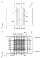
- FIG. 14(A) is a plan view showing an example of a heat sink 40 relating to Modification Example 2
- FIG. 14(B) is a plan view showing the state in which the first light source array 20A is mounted on the heat sink 40.
- the longitudinal direction of the heat sink 40 is the X2 direction
- the lateral direction is the Y2 direction
- the thickness direction is the Z2 direction.
- the X2 direction, Y2 direction, and Z2 direction are mutually perpendicular.
- the heat sink 40 extends in the Y2 direction and has multiple flow paths 403 through which the refrigerant flows from a refrigerant inlet 401 provided at one end of the heat sink 40 in the Y2 direction to a refrigerant outlet 402 provided at the other end in the Y2 direction.
- the LED chips 23A on the substrate 21A mounted on the heat sink 40, adjacent LED chips 23A in the X2 direction are connected in series.
- the groups of LED chips 23A connected in series are referred to as a first group G1, a second group G2, a third group G3, a fourth group G4, and a fifth group G5, in that order from the refrigerant inlet 401 toward the refrigerant outlet 402 (see FIG. 14B).
- FIG. 14(B) current flows through the LED chip 23A in the direction indicated by the arrow AR1 (+X2 direction). Meanwhile, the coolant in the heat sink 40 flows in the direction indicated by the arrow AR2 (-Y2 direction).
- the cooling effect of the refrigerant is greater closer to the refrigerant inlet 401, when the same current value is supplied to all LED chips 23A in the first light source array 20A, the temperature of the LED chips 23A increases from the refrigerant inlet 401 toward the refrigerant outlet 402. In other words, the closer the LED chip 23A is to the refrigerant inlet 401, the lower its temperature becomes.
- the current value supplied to each LED chip 23A cannot be made different for each LED chip 23A. Therefore, the current value supplied to LED chips 23A connected in series is uniformly controlled in the wiring direction (X2 direction).
- the substrate 21A is mounted on the heat sink 40 so that the wiring direction of the LED chip 23A (see arrow AR1) and the direction in which the coolant flows in the heat sink 40 (see arrow AR2) are perpendicular to each other.
- the LED chips 23A LED chips 23A included in the same group
- the wiring direction are approximately the same distance from the refrigerant inlet 401, and therefore the temperature changes in the same way. Therefore, by controlling the current value of the current supplied to each wiring (each group), the amount of light emitted by the light-emitting portion 231A of each LED chip 23A can be made uniform. Specifically, the current value of the current supplied to the LED chips 23A of the first group G1 closest to the refrigerant inlet 401 is made the lowest, and the current value of the current supplied to the group farther from the refrigerant inlet 401 is made higher.
- the current value of the current supplied to the LED chips 23A of the fifth group G5 is made the highest. This makes it possible to make the amount of light emitted by the light-emitting portion 231A of each of the multiple LED chips 23A included in the first light source array 20A approximately the same, thereby improving the illuminance uniformity. The same applies to the second light source array 20B.
- the LED chips 23A and LED chips 23B may be directly mounted on the heat sink 40.
- the illumination unit 90, 90A includes the first light source unit OPU1, the second light source unit OPU2, and the illumination optical system 80, 80A including the second dichroic mirror DM2, but is not limited to this.
- the illumination unit 90, 90A may include only one of the first light source unit OPU1 and the second light source unit OPU2.
- the illumination optical system 80, 80A can have any configuration as long as it can guide the light emitted from the first light source unit OPU1 or the second light source unit OPU2 to the mask MSK.
- the exposure apparatus has been described as being used to manufacture liquid crystal display devices (flat panel displays), but the exposure apparatus may also be used to manufacture semiconductors by exposing silicon wafers.
- Exposure apparatus 20A First light source array 20B Second light source array 21A, 21B Substrate 23A, 23B LED chip 40 Heat sink 80, 80A Illumination optical system 90, 90A Illumination unit 100 Projection optical unit CTR1 First controller CTR2 Second controller DM2 Second dichroic mirror FEL Fly's eye lens MSK Mask OPU1 First light source unit OPU2 Second light source unit PL Projection optical system P Glass substrate
Landscapes
- Physics & Mathematics (AREA)
- General Physics & Mathematics (AREA)
- Health & Medical Sciences (AREA)
- Life Sciences & Earth Sciences (AREA)
- Atmospheric Sciences (AREA)
- Toxicology (AREA)
- Engineering & Computer Science (AREA)
- Environmental & Geological Engineering (AREA)
- Epidemiology (AREA)
- Public Health (AREA)
- Exposure And Positioning Against Photoresist Photosensitive Materials (AREA)
Abstract
Description
まず、本実施形態に係る露光装置10の構成について説明する。図1は、本実施形態に係る露光装置10の構成を概略的に示す図である。
次に、本実施形態における照明系IOPの構成について説明する。照明系IOPは、投影光学系PLが備える複数の投影光学ユニット100それぞれに対応する複数の照明ユニット90を備える。
第1光源ユニットOPU1は、第1の光源アレイ20Aと、第1の拡大光学系30Aと、第1制御部CTR1と、を備え、第2光源ユニットOPU2は、第2の光源アレイ20Bと、第2の拡大光学系30Bと、第2制御部CTR2と、を備える。
再び図2を参照し、照明光学系80の構成について説明する。照明光学系80は、第1のダイクロイックミラーDM1を含んで構成される第1の集光光学系81Aと、第2の集光光学系81Bと、第2のダイクロイックミラーDM2と、結像光学系83と、フライアイレンズFELと、開口絞り85と、コンデンサー光学系84と、を備える。
第1光源ユニットOPU1及び第2光源ユニットOPU2が適用される照明ユニットは、上記実施形態に限られるものではない。図13は、変形例1に係る照明ユニット90Aの構成を示す概略図である。
上述したようにLEDチップ23Aが備える発光部231Aの発光量及びLEDチップ23Bが備える発光部231Bの発光量は、LEDチップ23A及び23Bの温度が上昇すると低下する。換言すると、LEDチップ23A及び23Bは、温度が上昇すると発光効率が低下する。
20A 第1の光源アレイ
20B 第2の光源アレイ
21A,21B 基板
23A,23B LEDチップ
40 ヒートシンク
80,80A 照明光学系
90,90A 照明ユニット
100 投影光学ユニット
CTR1 第1制御部
CTR2 第2制御部
DM2 第2のダイクロイックミラー
FEL フライアイレンズ
MSK マスク
OPU1 第1光源ユニット
OPU2 第2光源ユニット
PL 投影光学系
P ガラス基板
Claims (43)
- 光源素子の温度が第1の温度範囲内にあるときに第1電流値の電流を供給すると、第1の発光量で発光する前記光源素子の駆動方法であって、
前記光源素子を前記第1の発光量で発光する状態にするときに、前記第1電流値よりも低い第2電流値で前記光源素子への電流供給を開始することと、
前記光源素子へ供給する電流の電流値を前記第2電流値から前記第1電流値まで増加させることと、
を含む光源素子の駆動方法。 - 前記増加させることでは、前記光源素子へ供給する電流の電流値を前記第2電流値から前記第1電流値まで時間とともに増加させる、
請求項1に記載の光源素子の駆動方法。 - 前記増加させることでは、前記光源素子へ供給する電流の電流値を、前記第2電流値から前記第1電流値まで予め定められた第1の割合で増加させる、
請求項1または請求項2に記載の光源素子の駆動方法。 - 前記第1の割合は一定の割合である、
請求項3に記載の光源素子の駆動方法。 - 前記第1の割合は、前記第1電流値で前記光源素子へ電流供給を開始したときの前記光源素子の発光量の変化に基づいて決定される、
請求項3または請求項4に記載の光源素子の駆動方法。 - 前記光源素子へ供給する電流の電流値が、前記第2電流値から前記第1電流値になる前に、前記光源素子が前記第1の発光量で発光する、
請求項1から請求項5のいずれか一項に記載の光源素子の駆動方法。 - 前記光源素子へ供給する電流の電流値が、前記第1電流値になった後、前記光源素子は前記第1の発光量で発光を続ける、
請求項6に記載の光源素子の駆動方法。 - 前記第1の温度範囲は、20℃~90℃である、
請求項1から請求項7のいずれか一項に記載の光源素子の駆動方法。 - 前記光源素子は、前記光源素子の温度が第2の温度範囲内にあるときに前記第1電流値よりも低い第3電流値の電流を供給すると、前記第1の発光量よりも低い第2の発光量で発光し、
前記第1電流値の電流が供給され前記第1の発光量で発光している前記光源素子を、前記第2の発光量で発光する状態にするときに、前記光源素子へ供給する電流の電流値を、前記第1電流値から前記第3電流値まで減少させること、
を含む請求項1から請求項8のいずれか一項に記載の光源素子の駆動方法。 - 前記減少させることでは、前記光源素子へ供給する電流の電流値を前記第1電流値から前記第3電流値まで時間とともに減少させる、
請求項9に記載の光源素子の駆動方法。 - 前記減少させることでは、前記光源素子へ供給する電流の電流値を、前記第1電流値から前記第3電流値まで予め定められた第2の割合で減少させる、
請求項10に記載の光源素子の駆動方法。 - 前記第2の割合は一定の割合である、
請求項11に記載の光源素子の駆動方法。 - 前記第2の割合は、前記第1電流値の電流が供給され前記第1の発光量で発光している前記光源素子へ供給する電流の電流値を、前記第1電流値から前記第3電流値に変更したときの前記光源素子の発光量の変化に基づいて決定される、
請求項11または請求項12に記載の光源素子の駆動方法。 - 前記光源素子は、LED素子である、
請求項1から請求項13のいずれか一項に記載の光源素子の駆動方法。 - 前記光源素子から出射する光のピーク波長は、360~370nmの範囲内にある、
請求項1から請求項14のいずれか一項に記載の光源素子の駆動方法。 - 前記光源素子から出射する光のピーク波長は、380~390nmの範囲内にある、
請求項1から請求項14のいずれか一項に記載の光源素子の駆動方法。 - 前記光源素子から出射する光のピーク波長は、400~410nmの範囲内にある、
請求項1から請求項14のいずれか一項に記載の光源素子の駆動方法。 - 固定対象物の表面上に2次元配列され、各々の温度が第1の温度範囲内にあるときに第1電流値の電流を供給すると、第1の発光量で各々発光する複数の光源素子と、
前記複数の光源素子に供給する電流の値を制御する制御部と、
を備え、
前記制御部は、
前記複数の光源素子を前記第1の発光量で発光する状態にするときに、前記第1電流値よりも低い第2電流値で前記複数の光源素子への電流供給を開始し、
前記複数の光源素子へ供給する電流の電流値を前記第2電流値から前記第1電流値まで増加させる、
光源ユニット。 - 前記制御部は、前記複数の光源素子へ供給する電流の電流値を、前記第2電流値から前記第1電流値まで時間とともに増加させる、
請求項18に記載の光源ユニット。 - 前記制御部は、前記複数の光源素子へ供給する電流の電流値を、予め定められた第1の割合で前記第2電流値から前記第1電流値まで増加させる、
請求項18または請求項19に記載の光源ユニット。 - 前記第1の割合は一定の割合である、
請求項20に記載の光源ユニット。 - 前記第1の割合は、前記第1電流値で前記複数の光源素子へ電流供給を開始したときの前記複数の光源素子の発光量の変化に基づいて決定される、
請求項20または請求項21に記載の光源ユニット。 - 前記複数の光源素子へ供給する電流の電流値が、前記第2電流値から前記第1電流値になる前に、前記複数の光源素子が前記第1の発光量で発光する、
請求項18から請求項22のいずれか一項に記載の光源ユニット。 - 前記複数の光源素子へ供給する電流の電流値が、前記第1電流値になった後、前記複数の光源素子は前記第1の発光量で発光を続ける、
請求項23に記載の光源ユニット。 - 前記第1の温度範囲は、20℃~90℃である、
請求項18から請求項24のいずれか一項に記載の光源ユニット。 - 前記複数の光源素子は、前記複数の光源素子の温度が第2の温度範囲内にあるときに前記第1電流値よりも低い第3電流値の電流を供給すると、前記第1の発光量よりも低い第2の発光量で発光し、
前記制御部は、前記第1電流値の電流が供給され前記第1の発光量で発光している前記複数の光源素子を、前記第2の発光量で発光する状態にするときに、前記複数の光源素子へ供給する電流の電流値を、前記第1電流値から前記第3電流値まで減少させる、
請求項18から請求項25のいずれか一項に記載の光源ユニット。 - 前記制御部は、前記複数の光源素子へ供給する電流の電流値を、前記第1電流値から前記第3電流値まで時間とともに減少させる、
請求項26に記載の光源ユニット。 - 前記制御部は、前記複数の光源素子へ供給する電流の電流値を、予め定められた第2の割合で前記第1電流値から前記第3電流値まで減少させる、
請求項26または請求項27に記載の光源ユニット。 - 前記第2の割合は一定の割合である、
請求項28に記載の光源ユニット。 - 前記第2の割合は、前記第1電流値の電流が供給され前記第1の発光量で発光している前記複数の光源素子へ供給する電流の電流値を、前記第1電流値から前記第3電流値に変更したときの前記複数の光源素子の発光量の変化に基づいて決定される、
請求項28または請求項29に記載の光源ユニット。 - 前記複数の光源素子は、
第1方向に配列され、直列に接続された複数の第1の光源素子と、
前記第1方向と直交する第2方向において前記複数の第1の光源素子と離間し、前記第1方向に配列され、直列に接続された複数の第2の光源素子と、
を含み、
前記固定対象物は、ヒートシンクに搭載された基板であり、
前記ヒートシンクは、前記第2方向に延伸し前記ヒートシンクの前記第2方向における一端側に設けられた冷媒入口から前記第2方向における他端側に設けられた冷媒出口に向かって内部に冷媒が流れる複数の流路を有する、
請求項18から請求項30のいずれか一項に記載の光源ユニット。 - 前記複数の光源素子は、
第1方向に配列され、直列に接続された複数の第1の光源素子と、
前記第1方向と直交する第2方向において前記複数の第1の光源素子と離間し、前記第1方向に配列され、直列に接続された複数の第2の光源素子と、
を含み、
前記固定対象物は、ヒートシンクであり、
前記ヒートシンクは、前記第2方向に延伸し前記ヒートシンクの前記第2方向における一端側に設けられた冷媒入口から前記第2方向における他端側に設けられた冷媒出口に向かって内部に冷媒が流れる複数の流路を有する、
請求項18から請求項30のいずれか一項に記載の光源ユニット。 - 前記複数の光源素子は、複数のLED素子である、
請求項18から請求項32のいずれか一項に記載の光源ユニット。 - 前記複数の光源素子から出射する光のピーク波長は、360~370nmの範囲内にある、
請求項18から請求項32のいずれか一項に記載の光源ユニット。 - 前記複数の光源素子から出射する光のピーク波長は、380~390nmの範囲内にある、
請求項18から請求項32のいずれか一項に記載の光源ユニット。 - 前記複数の光源素子から出射する光のピーク波長は、400~410nmの範囲内にある、
請求項18から請求項32のいずれか一項に記載の光源ユニット。 - 前記光源ユニットは露光装置用である、
請求項18から請求項36のいずれか一項に記載の光源ユニット。 - 請求項18から請求項37のいずれか一項に記載の光源ユニットと、
前記光源ユニットから出射された光を被照射体に導く照明光学系と、
を備える照明ユニット。 - 複数の請求項18から請求項37のいずれか一項に記載の光源ユニットと、
複数の前記光源ユニットから出射された光を合成する合成光学素子を含み、前記合成光学素子から出射された合成光を被照射体に導く照明光学系と、
を備える照明ユニット。 - 請求項38又は請求項39に記載の照明ユニットと、
前記照明ユニットにより照明されるマスクのパターン像を感光性基板上に投影する投影光学系と、
を備える露光装置。 - 前記感光性基板は、少なくとも一辺の長さ又は対角長が500mm以上である、
請求項40に記載の露光装置。 - 請求項40または請求項41に記載の露光装置を用いた露光方法であって、
前記照明ユニットによりマスクを照明することと、
前記投影光学系を用いて前記マスクのパターン像を感光性基板へ投影することと、
を含む露光方法。 - 第1電流値の電流を供給すると、第1の発光量で発光する光源素子の駆動方法であって、
前記光源素子を前記第1の発光量で発光する状態にするときに、前記第1電流値よりも低い第2電流値で前記光源素子へ電流を供給することと、
前記光源素子へ供給する電流の電流値を前記第2電流値から前記第1電流値まで増加させることと、
を含む光源素子の駆動方法。
Priority Applications (5)
| Application Number | Priority Date | Filing Date | Title |
|---|---|---|---|
| PCT/JP2023/014082 WO2024209587A1 (ja) | 2023-04-05 | 2023-04-05 | 駆動方法、光源ユニット、照明ユニット、露光装置、及び露光方法 |
| CN202380096703.6A CN120958384A (zh) | 2023-04-05 | 2023-04-05 | 驱动方法、光源单元、照明单元、曝光装置、以及曝光方法 |
| KR1020257032365A KR20250160466A (ko) | 2023-04-05 | 2023-04-05 | 구동 방법, 광원 유닛, 조명 유닛, 노광 장치, 및 노광 방법 |
| JP2025512288A JPWO2024209587A1 (ja) | 2023-04-05 | 2023-04-05 | |
| TW113112678A TWI935383B (zh) | 2023-04-05 | 2024-04-03 | 驅動方法、光源單元、照明單元、曝光裝置、及曝光方法 |
Applications Claiming Priority (1)
| Application Number | Priority Date | Filing Date | Title |
|---|---|---|---|
| PCT/JP2023/014082 WO2024209587A1 (ja) | 2023-04-05 | 2023-04-05 | 駆動方法、光源ユニット、照明ユニット、露光装置、及び露光方法 |
Publications (1)
| Publication Number | Publication Date |
|---|---|
| WO2024209587A1 true WO2024209587A1 (ja) | 2024-10-10 |
Family
ID=92971440
Family Applications (1)
| Application Number | Title | Priority Date | Filing Date |
|---|---|---|---|
| PCT/JP2023/014082 Ceased WO2024209587A1 (ja) | 2023-04-05 | 2023-04-05 | 駆動方法、光源ユニット、照明ユニット、露光装置、及び露光方法 |
Country Status (4)
| Country | Link |
|---|---|
| JP (1) | JPWO2024209587A1 (ja) |
| KR (1) | KR20250160466A (ja) |
| CN (1) | CN120958384A (ja) |
| WO (1) | WO2024209587A1 (ja) |
Citations (4)
| Publication number | Priority date | Publication date | Assignee | Title |
|---|---|---|---|---|
| JP2007073984A (ja) * | 2003-01-16 | 2007-03-22 | Nikon Corp | 照明光源装置、露光装置及び露光方法 |
| JP2011237596A (ja) * | 2010-05-10 | 2011-11-24 | Hitachi High-Technologies Corp | 露光装置、露光方法、及び表示用パネル基板の製造方法 |
| JP2012220619A (ja) * | 2011-04-06 | 2012-11-12 | Hitachi High-Technologies Corp | 露光装置、露光方法、及び表示用パネル基板の製造方法 |
| JP2014090210A (ja) * | 2014-01-22 | 2014-05-15 | Nikon Corp | パターン形成装置、及びパターン形成方法 |
Family Cites Families (1)
| Publication number | Priority date | Publication date | Assignee | Title |
|---|---|---|---|---|
| JP5957262B2 (ja) | 2012-03-29 | 2016-07-27 | 株式会社オーク製作所 | 放電ランプを備えた照明装置 |
-
2023
- 2023-04-05 JP JP2025512288A patent/JPWO2024209587A1/ja active Pending
- 2023-04-05 WO PCT/JP2023/014082 patent/WO2024209587A1/ja not_active Ceased
- 2023-04-05 CN CN202380096703.6A patent/CN120958384A/zh active Pending
- 2023-04-05 KR KR1020257032365A patent/KR20250160466A/ko active Pending
Patent Citations (4)
| Publication number | Priority date | Publication date | Assignee | Title |
|---|---|---|---|---|
| JP2007073984A (ja) * | 2003-01-16 | 2007-03-22 | Nikon Corp | 照明光源装置、露光装置及び露光方法 |
| JP2011237596A (ja) * | 2010-05-10 | 2011-11-24 | Hitachi High-Technologies Corp | 露光装置、露光方法、及び表示用パネル基板の製造方法 |
| JP2012220619A (ja) * | 2011-04-06 | 2012-11-12 | Hitachi High-Technologies Corp | 露光装置、露光方法、及び表示用パネル基板の製造方法 |
| JP2014090210A (ja) * | 2014-01-22 | 2014-05-15 | Nikon Corp | パターン形成装置、及びパターン形成方法 |
Also Published As
| Publication number | Publication date |
|---|---|
| CN120958384A (zh) | 2025-11-14 |
| TW202447720A (zh) | 2024-12-01 |
| KR20250160466A (ko) | 2025-11-13 |
| JPWO2024209587A1 (ja) | 2024-10-10 |
Similar Documents
| Publication | Publication Date | Title |
|---|---|---|
| CN101069267A (zh) | 光学积分器、照明光学装置、曝光装置以及曝光方法 | |
| TW201413400A (zh) | 微影裝置、可程式化圖案化器件及微影方法 | |
| JP4678493B2 (ja) | 光源ユニット、照明光学装置、露光装置、および露光方法 | |
| KR20250160466A (ko) | 구동 방법, 광원 유닛, 조명 유닛, 노광 장치, 및 노광 방법 | |
| JP7806909B2 (ja) | 照明ユニット、露光装置、及び露光方法 | |
| TWI876438B (zh) | 光源單元、照明單元、曝光裝置、及曝光方法 | |
| WO2025069249A1 (ja) | 駆動方法、光源ユニット、照明ユニット、露光装置、及び露光方法 | |
| TWI920814B (zh) | 曝光裝置 | |
| TWI855790B (zh) | 光源單元、照明單元、曝光裝置、及曝光方法 | |
| WO2024209586A1 (ja) | 光源ユニット、照明ユニット、露光装置、及び露光方法 | |
| TWI915658B (zh) | 光源單元、照明單元、曝光裝置、及曝光方法 | |
| WO2024089737A1 (ja) | 合成光学素子、照明ユニット、露光装置、及び露光方法 | |
| WO2025013286A1 (ja) | 照明ユニット、露光装置、及び露光方法 | |
| WO2025079172A1 (ja) | 光源ユニット、照明ユニット、露光装置、及び露光方法 | |
| JP2026077090A (ja) | 光源装置、露光装置、及び物品の製造方法 | |
| JP2004207284A (ja) | 露光装置および露光方法 |
Legal Events
| Date | Code | Title | Description |
|---|---|---|---|
| 121 | Ep: the epo has been informed by wipo that ep was designated in this application |
Ref document number: 23931999 Country of ref document: EP Kind code of ref document: A1 |
|
| ENP | Entry into the national phase |
Ref document number: 2025512288 Country of ref document: JP Kind code of ref document: A |
|
| WWE | Wipo information: entry into national phase |
Ref document number: 2025512288 Country of ref document: JP |
|
| ENP | Entry into the national phase |
Ref document number: 1020257032365 Country of ref document: KR Free format text: ST27 STATUS EVENT CODE: A-0-1-A10-A15-NAP-PA0105 (AS PROVIDED BY THE NATIONAL OFFICE) |
|
| WWE | Wipo information: entry into national phase |
Ref document number: KR1020257032365 Country of ref document: KR |
|
| NENP | Non-entry into the national phase |
Ref country code: DE |
|
| 122 | Ep: pct application non-entry in european phase |
Ref document number: 23931999 Country of ref document: EP Kind code of ref document: A1 |