WO2024209329A1 - 焼成用容器 - Google Patents
焼成用容器 Download PDFInfo
- Publication number
- WO2024209329A1 WO2024209329A1 PCT/IB2024/053140 IB2024053140W WO2024209329A1 WO 2024209329 A1 WO2024209329 A1 WO 2024209329A1 IB 2024053140 W IB2024053140 W IB 2024053140W WO 2024209329 A1 WO2024209329 A1 WO 2024209329A1
- Authority
- WO
- WIPO (PCT)
- Prior art keywords
- container
- lid
- core tube
- furnace core
- firing
- Prior art date
- Legal status (The legal status is an assumption and is not a legal conclusion. Google has not performed a legal analysis and makes no representation as to the accuracy of the status listed.)
- Ceased
Links
Images






Classifications
-
- F—MECHANICAL ENGINEERING; LIGHTING; HEATING; WEAPONS; BLASTING
- F27—FURNACES; KILNS; OVENS; RETORTS
- F27B—FURNACES, KILNS, OVENS OR RETORTS IN GENERAL; OPEN SINTERING OR LIKE APPARATUS
- F27B7/00—Rotary-drum furnaces, i.e. horizontal or slightly inclined
- F27B7/06—Rotary-drum furnaces, i.e. horizontal or slightly inclined adapted for treating the charge in vacuum or special atmosphere
-
- F—MECHANICAL ENGINEERING; LIGHTING; HEATING; WEAPONS; BLASTING
- F27—FURNACES; KILNS; OVENS; RETORTS
- F27B—FURNACES, KILNS, OVENS OR RETORTS IN GENERAL; OPEN SINTERING OR LIKE APPARATUS
- F27B7/00—Rotary-drum furnaces, i.e. horizontal or slightly inclined
- F27B7/08—Rotary-drum furnaces, i.e. horizontal or slightly inclined externally heated
-
- F—MECHANICAL ENGINEERING; LIGHTING; HEATING; WEAPONS; BLASTING
- F27—FURNACES; KILNS; OVENS; RETORTS
- F27B—FURNACES, KILNS, OVENS OR RETORTS IN GENERAL; OPEN SINTERING OR LIKE APPARATUS
- F27B9/00—Furnaces through which the charge is moved mechanically, e.g. of tunnel type; Similar furnaces in which the charge moves by gravity
- F27B9/14—Furnaces through which the charge is moved mechanically, e.g. of tunnel type; Similar furnaces in which the charge moves by gravity characterised by the path of the charge during treatment; characterised by the means by which the charge is moved during treatment
- F27B9/20—Furnaces through which the charge is moved mechanically, e.g. of tunnel type; Similar furnaces in which the charge moves by gravity characterised by the path of the charge during treatment; characterised by the means by which the charge is moved during treatment the charge moving in a substantially straight path
- F27B9/24—Furnaces through which the charge is moved mechanically, e.g. of tunnel type; Similar furnaces in which the charge moves by gravity characterised by the path of the charge during treatment; characterised by the means by which the charge is moved during treatment the charge moving in a substantially straight path being carried by a conveyor
-
- F—MECHANICAL ENGINEERING; LIGHTING; HEATING; WEAPONS; BLASTING
- F27—FURNACES; KILNS; OVENS; RETORTS
- F27D—DETAILS OR ACCESSORIES OF FURNACES, KILNS, OVENS OR RETORTS, IN SO FAR AS THEY ARE OF KINDS OCCURRING IN MORE THAN ONE KIND OF FURNACE
- F27D3/00—Charging; Discharging; Manipulation of charge
- F27D3/12—Travelling or movable supports or containers for the charge
Definitions
- the present invention relates to an apparatus for manufacturing an oxide that can be used as a positive electrode active material, and a firing container that can be used in the apparatus. It also relates to a method for manufacturing a positive electrode active material.
- lithium-ion secondary batteries lithium-ion capacitors
- air batteries air batteries
- all-solid-state batteries all-solid-state batteries.
- high-output, high-capacity lithium-ion secondary batteries has rapidly expanded in line with the development of the semiconductor industry, and they have become indispensable in today's information society as a rechargeable energy source.
- Patent Document 1 discloses a method for producing positive electrode active materials using a rotary kiln that allows for continuous processing.
- Positive electrode active materials are one of the most expensive materials in lithium-ion secondary batteries, and there is a great effect in improving productivity. At the same time, there is also a strong demand for higher performance (for example, higher capacity, improved cycle characteristics, improved reliability or safety).
- an object of one embodiment of the present invention is to provide a method for manufacturing a positive electrode active material at low production costs.
- an object of the present invention is to provide a container capable of manufacturing a positive electrode active material at low production costs.
- an object of the present invention is to provide a manufacturing apparatus capable of manufacturing a positive electrode active material at low production costs.
- an object of the present invention is to provide a method for manufacturing a positive electrode active material whose crystal structure is not easily destroyed even after repeated charging and discharging.
- an object of the present invention is to provide a method for manufacturing a positive electrode active material with excellent charge and discharge cycle characteristics.
- an object of the present invention is to provide a method for manufacturing a positive electrode active material with large charge and discharge capacity.
- an object of the present invention is to provide a secondary battery with high reliability or safety.
- the positive electrode active material is a lithium oxide LiMO 2 (M is one or more metals including Co, and the substitution position of the metal is not particularly limited).
- some of the materials to be heat-treated may function as a flux.
- This function allows the heating temperature to be lowered below the decomposition temperature of lithium cobalt oxide, for example to 742°C or higher and 950°C or lower, and additive elements such as magnesium can be distributed in the surface layer, making it possible to manufacture a positive electrode active material with good characteristics.
- the presence of additive elements such as magnesium in the surface layer can suppress excessive reaction between the positive electrode active material and the electrolyte during charge/discharge cycles. Or, it can suppress the release of oxygen from the positive electrode active material.
- LiF has a lower specific gravity in a gaseous state than oxygen
- LiF may volatilize when heated, and when it volatilizes, the amount of LiF in the material to be heat-treated decreases. This weakens its function as a flux. Therefore, it is necessary to heat while suppressing the volatilization of LiF.
- LiF is not used as the fluorine source, etc.
- Li on the LiMO2 surface may react with F of the fluorine source to produce LiF, which may volatilize. Therefore, even if a fluoride with a higher melting point than LiF is used, it is necessary to suppress the volatilization in the same way.
- a closed space refers to a space that is surrounded by solids (walls) on all sides at a certain point at room temperature.
- a space with a gate valve is called a closed space when the gate valve is closed, and a container with a lid on is also called a closed space.
- the container is made of a heat-resistant material (heat-resistant material) to heat the container to 742°C or higher using LiF as a flux, and a lid is placed around the periphery of the top opening of the container. Since the container is heated with the lid on, it is preferable to make the lid (also called the lid body) from a material with the same thermal expansion coefficient. By placing the lid on, the flow of gas between the outside and inside of the container can be prevented.
- heat-resistant material heat-resistant material
- a screw thread is provided in a spiral shape on the part of the lid that contacts the container, and a screw groove is provided in a spiral shape on the inner peripheral surface of the opening of the container, and the lid or the container are rotated to seal the lid or the container relative to each other (also called a screw-top structure).
- Linear screw threads are formed at equal intervals on this lid. This structure can be said to be such that in the contact area between the lid and the container when the opening of the container is closed with the lid, the area occupied by the curved surface (area of the area without the screw thread) is smaller than the area occupied by the unevenness (area of the area with the screw thread).
- the contact area between the lid and the container is in contact at room temperature, during or after heating at 800°C or higher, depending on the thermal expansion coefficient of the material, a small gap may be generated through the gap, through which outside air (oxygen atmosphere) may enter, or gas may be released from inside the container. Even if a gap is generated between the lid and the container during or after heating, it is preferable that the gap is narrower than the average particle size of the powder.
- the configuration of the invention disclosed in this specification is such that the contact area between the lid and the container when the opening of the container is closed with the lid does not have a continuous thread or screw groove over a wide area.
- the firing container has a lid made of a heat-resistant material and a container with an opening, where the lid and container are made of the same material, the lid and container are combined to form a closed space, and the contact area between the lid and the container when the opening of the container is closed with the lid is the side of the lid and the inner wall of the container, which is the firing container.
- the firing container includes members including the container and lid, and also includes handles, patterns, and protrusions for removal, if any.
- the outer diameter of the lid and the inner diameter of the container are the same.
- the heat-resistant alloy used is an alloy that combines two or more elements selected from nickel, chromium, molybdenum, zirconium, titanium, niobium, vanadium, scandium, manganese, and yttrium.
- an oxide film may form on the surface. The formation of this oxide film on the surface of the container and the surface of the lid can further improve heat resistance.
- the oxide film formed on the surface of the container and the surface of the lid improves corrosion caused by the acid used during cleaning.
- the lithium oxide or fluorine source is a powder, and the stirring process is performed efficiently by moving the container in which it is stored. Specifically, a cylindrical container with a lid is rotated.
- the container be cylindrical, but it may also be shaped like a prism (a triangular prism, a polygonal prism with more than a square prism) in order to stir the powder inside the container by applying an impact when the container is rotated.
- the lithium oxide or fluorine source is a powder, and even if it is placed in a container and the lid is put on, if the powder adheres to the contact area between the container and the lid, the lid will stick to the container, and there is a risk that the lid will not open.
- a convex portion may be provided on the inside of the container to prevent the powder from moving near the contact area between the lid and the container (anti-adhesion means).
- the invention disclosed in this specification is a firing container having a lid made of a heat-resistant material and a container with an opening, the lid and container being made of the same material, the lid and container being combined to form a closed space, and when the opening of the container is closed with the lid, the contact area between the lid and the container has an area without irregularities that is larger than the area occupied by the irregularities.
- a means for preventing adhesion may be further provided on the inner wall of the container.
- the outer diameter of the lid and the inner diameter of the container may be the same.
- a firing container having a lid made of a heat-resistant material and a container having an opening, the lid and the container being made of the same material, the inner wall of the container having a groove, the outer periphery of the lid having a protrusion that fits into the groove, and the contact area between the lid and the container when the opening of the container is closed with the lid being the protrusion and the inner wall.
- the surface of the lid or the surface of the container has an oxide film of a heat-resistant material.
- This oxide film is formed by heating in an oxygen atmosphere. By providing this oxide film on the surface, the container and lid can be cleaned by acid washing, etc.
- the container can be heated with the lid on to prevent gas from leaking out.
- the anti-adhesion means prevents the container and lid from adhering, allowing the container to be opened and closed freely.
- the powdered material can be heated and stirred at the same time for efficient heat treatment.
- the total heating time can be shortened by putting a lid on to prevent heat from escaping, rotating the container to stir, and efficiently heat treating the material.
- the container can be stored with the lid on even after heating, and as it is not exposed to the air and its quality can be maintained for a long period of time, it can also be used as a storage container for positive electrode active material.
- FIG. 1 is a perspective view showing an example of a lid and a container according to one embodiment of the present invention.
- FIG. 2 is a perspective view showing an example of a lid and a container according to one embodiment of the present invention.
- FIG. 3 is a perspective view showing an example of a lid and a container according to one embodiment of the present invention.
- FIG. 4 is a perspective view showing an example of a lid and a container according to one embodiment of the present invention.
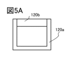
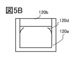
- 5A, 5B, 5C, 5D, 5E, 5F, and 5G are cross-sectional views showing examples of a lid and a container according to one embodiment of the present invention.
- FIG. 6A is a cross-sectional view of a production apparatus showing one embodiment of the present invention, and FIG.
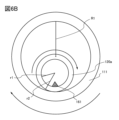
- FIG. 6B is a schematic view showing cross sections of a furnace tube and a container.
- FIG. 7 is a cross-sectional view of a manufacturing apparatus showing one embodiment of the present invention.
- FIG. 8 is a schematic diagram showing a cross section of a roller and a container according to one embodiment of the present invention.
- Figure 1 is a perspective view of the lid and container, showing the lid 120b and container 120a at a distance.
- FIG. 1 is a perspective view of the container with the lid on.
- Figure 2 shows the lid of Figure 1 rotated 90 degrees to fit into the groove of the container.
- Figures 1 and 2 show an example in which the protrusions 120c are provided in two places on the lid 120b, but this is not particularly limited and they may be provided in three or more places, and the shape is also not particularly limited.
- the outer diameter of the lid 120b and the inner diameter of the container 120a are the same. Therefore, when the opening of the container is closed with the lid, the contact area between the lid and the container is the side of the lid and the inner wall of the container. Furthermore, when metal is used as the material for the container 120a and the lid 120b, an oxide film is formed on the surface of the container and the surface of the lid, and this oxide film improves corrosion caused by the acid used during cleaning.
- the area of the contact between the lid and the container is occupied by a curved surface without a thread or groove, which is larger than the area of the unevenness with a thread or groove.
- the unevenness used to fit the lid and the container includes a thread or groove.
- the unevenness for fitting is limited to two protrusions 120c on the side of the lid 120b and an L-shaped groove on the inner wall of the container 120a.
- the lid and the container may become stuck together after heat treatment, making it impossible to open or close.
- Figure 5A shows a cross-sectional view of the lid and container corresponding to Figure 2. Note that the same reference numerals are used in Figure 5A for the same parts as those shown in Figure 2.
- anti-adhesion means 120d may be provided on the inner wall of the container 120a, and a cross-sectional view of one example is shown in FIG. 5B.
- the anti-adhesion means 120d is in the form of a thin plate.
- FIG. 5C a cross-sectional view of an example is shown in FIG. 5C.
- the outer diameter of the lid is the same as in FIG. 5A, but the depth of the container 120a is different.
- the inner wall may be partially thickened to serve as an anti-sticking means, and the outer diameter of the lid may be reduced.
- Figure 5D shows a cross-sectional view of one example of this.
- the outer diameter of the container 120a is the same as in Figure 5A.
- Figures 1 and 2 show an example in which the lid has a convex portion (cylindrical protrusion) on the side, this is not particularly limited, and a convex portion may be provided on the inner wall of the container and an L-shaped groove may be provided on the side of the lid. Also, as shown in Figure 3, the lid may have a configuration in which there is no convex portion on the side of the lid (disk-shaped top plate).
- FIG 3 shows another example, in which the opening of the container is configured to fit into the opening of the lid.
- Figure 4 shows a perspective view of the container with the lid removed, with anti-sticking means 120d provided inside the container.
- Figure 5E shows a cross-sectional view of the lid and container corresponding to Figures 3 and 4. Note that the same reference numerals are used in Figure 5E for the same parts as in Figure 3.
- anti-sticking means 120d is also provided, and the anti-sticking means 120d has a hollow disk shape.
- Figure 5F shows an example that is partially different from Figure 5E.
- the side of the lid 120b is in contact with the container 120a, and the outer diameter of the lid 120b is smaller than the outer diameter of the container 120a.
- the powder is present at the bottom of the container below the adhesion prevention means 120d, and the adhesion prevention means 120d prevents the powder from moving near the container and lid even when the container is turned sideways.
- Figure 5G shows an example that is slightly different from Figure 5E.
- part of the inner wall of the container is made thicker to prevent adhesion.
- the bottom surface of the container 120a is flat, but this is not particularly limited, and the cross-sectional shape of the lower end of the container may be rounded in a U-shape.
- the overall height of the container 120a can be 10 cm or more and 50 cm or less. If the container is cylindrical, the outer diameter of the container 120a can be 3 cm or more and 30 cm or less.
- the covered container 120a When carrying out the heat treatment, the covered container 120a is turned sideways and the side surface (also called the peripheral wall) of the container 120a is placed down, and the container is rotated to agitate the powder inside.
- the container 120a rotates about the central axis of the peripheral wall. Even after heating, the lid does not stick to the container at the contact point, and the lid can be easily attached and detached.
- a handle may also be provided on the lid to make it easier to remove.
- FIG. 6A shows an example of a cross-sectional view of a rotary kiln apparatus.
- the manufacturing apparatus shown in FIG. 6A is suitable for producing a positive electrode active material (LCO, NCM, LFP, etc.).
- LCO positive electrode active material
- the mixture is placed in a container, and the container is rotated under an oxygen gas atmosphere to stir the material to be heat-treated while performing heat treatment.
- the mixture is at least a fluoride, for example, a mixture of lithium fluoride (LiF) and magnesium fluoride (MgF 2 ).
- the melting point of the fluoride including lithium fluoride
- it can function as a flux (also called a fluxing agent) that lowers the melting point of the other additive element source.
- a flux also called a fluxing agent
- the fluoride has LiF and MgF2 , since the eutectic point P of LiF and MgF2 is around 742°C, it is preferable to set the heating temperature to 742°C or higher in the heat treatment after mixing the additive element.
- Figure 6A shows a schematic cross-sectional view of a manufacturing apparatus 110 according to one embodiment of the present invention.
- the manufacturing apparatus 110 has a rotating furnace core tube 111, a heating means 112, a vibration means 119, and a stage 118.
- the manufacturing apparatus 110 also has a rotation drive device 115 for the furnace core tube 111, a gas supply means 116a, and a gas exhaust means 116b.
- a container 120a containing material is placed in the furnace core tube 111.
- the furnace core tube 111 is a thick cylinder with one end being a supply port and the other end being an unloading port.
- the furnace core tube 111 rotates to agitate the workpiece contained in the container 120a, i.e., the material to be heat-treated.
- the heating means 112 is arranged around the furnace core tube 111 and has the function of heating to 700°C or more and 1200°C or less.
- a silicon carbide heater, a carbon heater, a metal heater, or a molybdenum disilicide heater can be used as the heating means 112.
- the gas supply means 116a has the function of controlling the atmosphere inside the furnace core tube 111 (also called the processing chamber).
- An example of the gas supply means 116a is a gas introduction line.
- the gas introduced is oxygen.
- the internal gas is first exhausted by the gas exhaust means 116b, and then oxygen gas is supplied from the gas supply means 116a to create the desired oxygen atmosphere.
- the oxygen gas may also be heated before being supplied into the furnace core tube from the gas supply means 116a.
- the gas exhaust means 116b may be provided with a pump for exhausting gas from inside the furnace core tube 111, a valve for preventing backflow, and a detoxification device (combustion detoxification device or plasma detoxification device) for rendering the gas harmless before it is released into the outside air.
- a detoxification device combustion detoxification device or plasma detoxification device
- a gate valve for simplicity, nothing is shown on either end of the furnace core tube 111 in FIG. 6A, but a gate valve, a glove box, a load chamber, an unload chamber, or a quartz cover is provided.
- a gate valve or the like is provided on either end of the furnace core tube 111. After creating an oxygen atmosphere, a heat treatment may be performed without supplying oxygen and with both ends of the furnace core tube 111 closed.
- the oxygen atmosphere inside the furnace core tube 111 may be controlled based on an oxygen concentration meter.
- the axis (central axis) of the furnace core tube 111 is not inclined relative to the horizontal plane, but the axis of the furnace core tube 111 may be inclined relative to the horizontal plane (or the plane of the stage 118) and the container loading side may be raised to make it easier to move the container inside the furnace core tube.
- the inclination angle of the axis of the furnace core tube can be changed by the practitioner as appropriate.
- the material in the container can also be stirred by increasing the rotation speed of the furnace core tube, but if the rotation speed of the furnace core tube is increased too much, the axis of the furnace core tube is inclined, so the container moves inside the furnace core tube, and the time it takes to reach an area without a heater becomes shorter, and sufficient heat treatment is not performed.
- the material may be biased against the inner wall of the container due to centrifugal force, and may not be mixed. Therefore, it is preferable for the practitioner to adjust the rotation speed of the furnace core tube and the inclination angle of the axis as appropriate so that the heat treatment can be performed for a sufficient period of time.
- FIG. 6A shows an example in which two containers are arranged, this is not a limitation and three or more containers may be arranged.
- an oxide film is formed on the surfaces of the containers and the lids, and this oxide film improves corrosion caused by the acid used during cleaning.
- the container 120a may be moved inside the furnace core tube by pushing out one end of the container 120a using a transport robot installed in the load chamber.
- the movement of the container 120a inside the furnace core tube is not limited to a constant speed, and the container 120a may be moved to a position close to the heating means, rotated on the spot, heated while stirring, and pushed out to end the heating process after sufficient heating.
- Figure 6A shows an example in which vibration means 119 is provided in the vertical direction to vibrate the container, but this is not particularly limited, and if sufficient stirring can be achieved and vibration means 119 is not necessary, it is not necessary to provide it.
- the vibration means 119 periodically moves up and down during the heating process.
- the vibration means 119 is provided in the gap of the heating means 112 surrounding the furnace core tube 111.
- a metal bar is used as the vibration means 119, and the metal bar is moved up and down by its own weight and a lifting mechanism using a spring or airflow, which impacts the furnace core tube and vibrates the container in contact with the inner wall of the furnace core tube.
- FIG. 6A the outer diameter R2 of the furnace core tube 111 is also shown.
- the material of the furnace core tube 111 may be a heat-resistant material, and may be the same material (heat-resistant alloy or ceramics) as the above-mentioned container 120a.
- FIG. 6B shows a cross-sectional view of the furnace core tube 111 and the container 120a cut in a circular cut, and illustrates the direction of rotation.
- FIG. 6B also shows the inner diameter R1 of the furnace core tube 111.
- the outer diameter r2 of the container 120a is set to be half or more and 9/10 or less of the inner diameter R1 of the furnace core tube.
- the outer diameter r2 of the container can be made larger, and the closer it is to the inner diameter R1 of the furnace core tube, the more the amount of material that can be heated at one time can be increased.
- the outer diameter r2 of the container and the inner diameter R1 of the furnace core tube are set to the optimal numerical range.
- a manufacturing apparatus can be provided that can obtain a large amount of positive electrode active material at once without introducing impurities by heat-treating the container while sealing the powdered workpiece 161 with a lid.
- FIG. 3 As an embodiment of the manufacturing apparatus of the present invention, an example of a roller hearth kiln for continuously treating objects contained in a container is shown.
- FIG. 3 As an embodiment of the manufacturing apparatus of the present invention, an example of a roller hearth kiln for continuously treating objects contained in a container is shown.
- the roller hearth kiln 150 has a kiln body 151, multiple rollers 152, heating means 153a, heating means 153b, heating means 153j, and heating means 153k, atmosphere control means 154, and vibration means 155a, vibration means 155b, and vibration means 155c.
- the roller hearth kiln 150 also preferably has one or more blocking plates 157 and measuring devices 160a and 160b.
- Figure 7 shows an example having three blocking plates 157 (shown as blocking plate 157a, blocking plate 157b, blocking plate 157c, and shielding plate 157d).
- the kiln body 151 is tunnel-shaped.
- the multiple rollers 152 have the function of transporting the container 120a containing the workpiece 161.
- the container 120a is transported by the multiple rollers 152 through the tunnel-shaped kiln body 151 to the outside.
- the kiln body 151 has an upstream portion and a downstream portion along the conveying direction of the multiple rollers 152.
- the kiln body 151 has a heating means 153a in the upstream portion and a heating means 153b in the downstream portion.
- a blocking plate 157b may be provided between the upstream portion and the downstream portion. By providing the blocking plate 157b, the atmosphere in the upstream portion and the downstream portion can be controlled separately. Also, a blocking plate 157b may be provided near the entrance of the kiln body 151, and a blocking plate 157c may be provided near the exit. By providing these, it becomes easier to control the atmosphere inside the kiln body 151.
- the vibration means 155 of the roller hearth kiln 150 is, for example, a means for vibrating the container 120a.
- it may be a rod-shaped or plate-shaped device provided between multiple rollers 152, such as the three vibration means 155 (shown as vibration means 155a, vibration means 155b, and vibration means 155c) shown in FIG. 7.
- the vibration means 155a, vibration means 155b, and vibration means 155c may be fixed, or may move to vibrate the container 120a.
- FIG. 7 shows a configuration in which three vibration means 155 are provided, this is not a limitation of one aspect of the present invention.
- One or two vibration means 155 may be provided, or four or more vibration means 155 may be provided.
- the description of the heating means 112 in embodiment 2 can be referred to.
- the roller hearth kiln 150 is highly productive and is preferred because it continuously processes the workpiece 161.
- the present invention is not limited to the roller hearth kiln 150 shown in FIG. 7.
- a container 120a is placed on two rollers 152, a heating means (not shown) is provided above or below, and the workpiece 161 is heated while rotating the two rollers.
- the container 120a is moved with the lid closed using a transport means, specifically a transport robot.
- the next container containing the workpiece 161 to be heated is placed on the two rollers 152 and heated.
- the heating process may be performed sequentially.
- the two rollers 152 rotate in different directions to agitate the powder inside the container, and are not used for transport, which is different from FIG. 7.
- the rollers are rotated in the same direction for transport.
- the apparatus shown in this embodiment is similar to the apparatus of embodiment 2 in that the container is covered and the heat treatment is performed while rotating the container. Also, when metal is used as the material for the container 120a and the lid 120b, an oxide film is formed on the surface of the container and the surface of the lid, and this oxide film prevents corrosion caused by the acid used during cleaning, which is also similar to the apparatus of embodiment 2.
- Vibration means 120a: Container, 120b: Lid, 120c: Convex portion, 120d: Anti-adhesion means, 150: Roller hearth kiln, 151: Kiln body, 152: Roller, 153a: Heating means, 153b: Heating means, 154: Atmosphere control means, 155a: Vibration means, 155b: Vibration means, 155c: Vibration means, 155: Vibration means, 157a: Shield plate, 157b: Shield plate, 157c: Shield plate, 157: Shield plate, 160a: Measuring device, 160b: Measuring device, 161: Workpiece
Landscapes
- Engineering & Computer Science (AREA)
- Mechanical Engineering (AREA)
- General Engineering & Computer Science (AREA)
- Battery Electrode And Active Subsutance (AREA)
Priority Applications (1)
| Application Number | Priority Date | Filing Date | Title |
|---|---|---|---|
| JP2025512207A JPWO2024209329A1 (https=) | 2023-04-07 | 2024-04-01 |
Applications Claiming Priority (2)
| Application Number | Priority Date | Filing Date | Title |
|---|---|---|---|
| JP2023062709 | 2023-04-07 | ||
| JP2023-062709 | 2023-04-07 |
Publications (1)
| Publication Number | Publication Date |
|---|---|
| WO2024209329A1 true WO2024209329A1 (ja) | 2024-10-10 |
Family
ID=92971385
Family Applications (1)
| Application Number | Title | Priority Date | Filing Date |
|---|---|---|---|
| PCT/IB2024/053140 Ceased WO2024209329A1 (ja) | 2023-04-07 | 2024-04-01 | 焼成用容器 |
Country Status (2)
| Country | Link |
|---|---|
| JP (1) | JPWO2024209329A1 (https=) |
| WO (1) | WO2024209329A1 (https=) |
Citations (5)
| Publication number | Priority date | Publication date | Assignee | Title |
|---|---|---|---|---|
| JPS5148155U (https=) * | 1974-10-07 | 1976-04-10 | ||
| JPS59172737U (ja) * | 1983-05-09 | 1984-11-19 | 三菱製鋼株式会社 | 焼結炉用収納箱内の敷板の支持体 |
| JPH09105585A (ja) * | 1995-10-05 | 1997-04-22 | Murata Mfg Co Ltd | 焼成装置 |
| JP2000335989A (ja) * | 1999-05-27 | 2000-12-05 | Kyocera Corp | 炭化ホウ素質焼結体およびその製造方法、セラミック焼成用治具並びにそれを用いた窒化物系セラミック部材の製造方法 |
| JP2017178681A (ja) * | 2016-03-30 | 2017-10-05 | 東京窯業株式会社 | リチウム電池の正極活物質用熱処理容器 |
-
2024
- 2024-04-01 JP JP2025512207A patent/JPWO2024209329A1/ja active Pending
- 2024-04-01 WO PCT/IB2024/053140 patent/WO2024209329A1/ja not_active Ceased
Patent Citations (5)
| Publication number | Priority date | Publication date | Assignee | Title |
|---|---|---|---|---|
| JPS5148155U (https=) * | 1974-10-07 | 1976-04-10 | ||
| JPS59172737U (ja) * | 1983-05-09 | 1984-11-19 | 三菱製鋼株式会社 | 焼結炉用収納箱内の敷板の支持体 |
| JPH09105585A (ja) * | 1995-10-05 | 1997-04-22 | Murata Mfg Co Ltd | 焼成装置 |
| JP2000335989A (ja) * | 1999-05-27 | 2000-12-05 | Kyocera Corp | 炭化ホウ素質焼結体およびその製造方法、セラミック焼成用治具並びにそれを用いた窒化物系セラミック部材の製造方法 |
| JP2017178681A (ja) * | 2016-03-30 | 2017-10-05 | 東京窯業株式会社 | リチウム電池の正極活物質用熱処理容器 |
Also Published As
| Publication number | Publication date |
|---|---|
| JPWO2024209329A1 (https=) | 2024-10-10 |
Similar Documents
| Publication | Publication Date | Title |
|---|---|---|
| US12188722B2 (en) | Multistage vertical graphitization furnace system | |
| JP7090784B1 (ja) | 熱処理システム、それが備える匣鉢及び熱処理方法 | |
| JP2011112288A (ja) | 回転撹拌型熱処理装置 | |
| US20230357888A1 (en) | Energy efficient salt-free recovery of metal from dross | |
| CN108883944A (zh) | 用于阴极材料的制造过程中的干燥程序 | |
| JP6213487B2 (ja) | 縦型熱処理装置の運転方法、記憶媒体及び縦型熱処理装置 | |
| JP5689649B2 (ja) | 回転炉 | |
| JP2019184211A (ja) | 焼成装置 | |
| WO2024209329A1 (ja) | 焼成用容器 | |
| CN112146433A (zh) | 一种可控气氛回转窑及其实现方法 | |
| KR102328768B1 (ko) | 고순도 분말 제조장치 | |
| KR102595314B1 (ko) | 분리형 수직 흑연화로 시스템 | |
| JP6894974B2 (ja) | 原料供給装置および供給方法 | |
| KR102948531B1 (ko) | 마이크로파 가열 장치 | |
| WO2013099894A1 (ja) | 基板処理装置及びそれを用いた基板処理方法 | |
| JP4485321B2 (ja) | 回分式加熱炉 | |
| KR101459187B1 (ko) | 구형체 물질의 고른 코팅을 위한 cvd 장치 | |
| KR102958629B1 (ko) | 마이크로파 가열 장치 | |
| KR102881924B1 (ko) | 산화티타늄 제조장치 및 이 장치를 이용한 산화티타늄 제조방법 | |
| JP2799172B2 (ja) | 真空熱処理炉 | |
| KR102832691B1 (ko) | 마이크로파 가열 장치 | |
| JPH09211164A (ja) | 核燃料再生用酸化・還元炉 | |
| JP2019100671A (ja) | 熱処理装置 | |
| JP7625648B2 (ja) | 熱処理装置及び熱処理方法 | |
| CN222812134U (zh) | 一种锂离子电池材料合成回转窑装置 |
Legal Events
| Date | Code | Title | Description |
|---|---|---|---|
| 121 | Ep: the epo has been informed by wipo that ep was designated in this application |
Ref document number: 24784491 Country of ref document: EP Kind code of ref document: A1 |
|
| WWE | Wipo information: entry into national phase |
Ref document number: 2025512207 Country of ref document: JP |
|
| NENP | Non-entry into the national phase |
Ref country code: DE |
|
| 122 | Ep: pct application non-entry in european phase |
Ref document number: 24784491 Country of ref document: EP Kind code of ref document: A1 |