WO2024204612A1 - 動力伝達装置及び継手装置 - Google Patents
動力伝達装置及び継手装置 Download PDFInfo
- Publication number
- WO2024204612A1 WO2024204612A1 PCT/JP2024/012822 JP2024012822W WO2024204612A1 WO 2024204612 A1 WO2024204612 A1 WO 2024204612A1 JP 2024012822 W JP2024012822 W JP 2024012822W WO 2024204612 A1 WO2024204612 A1 WO 2024204612A1
- Authority
- WO
- WIPO (PCT)
- Prior art keywords
- power transmission
- rotating
- rotating body
- planetary
- power
- Prior art date
- Legal status (The legal status is an assumption and is not a legal conclusion. Google has not performed a legal analysis and makes no representation as to the accuracy of the status listed.)
- Ceased
Links
Images


Classifications
-
- F—MECHANICAL ENGINEERING; LIGHTING; HEATING; WEAPONS; BLASTING
- F16—ENGINEERING ELEMENTS AND UNITS; GENERAL MEASURES FOR PRODUCING AND MAINTAINING EFFECTIVE FUNCTIONING OF MACHINES OR INSTALLATIONS; THERMAL INSULATION IN GENERAL
- F16H—GEARING
- F16H3/00—Toothed gearings for conveying rotary motion with variable gear ratio or for reversing rotary motion
- F16H3/44—Toothed gearings for conveying rotary motion with variable gear ratio or for reversing rotary motion using gears having orbital motion
- F16H3/62—Gearings having three or more central gears
- F16H3/66—Gearings having three or more central gears composed of a number of gear trains without drive passing from one train to another
-
- A—HUMAN NECESSITIES
- A61—MEDICAL OR VETERINARY SCIENCE; HYGIENE
- A61F—FILTERS IMPLANTABLE INTO BLOOD VESSELS; PROSTHESES; DEVICES PROVIDING PATENCY TO, OR PREVENTING COLLAPSING OF, TUBULAR STRUCTURES OF THE BODY, e.g. STENTS; ORTHOPAEDIC, NURSING OR CONTRACEPTIVE DEVICES; FOMENTATION; TREATMENT OR PROTECTION OF EYES OR EARS; BANDAGES, DRESSINGS OR ABSORBENT PADS; FIRST-AID KITS
- A61F2/00—Filters implantable into blood vessels; Prostheses, i.e. artificial substitutes or replacements for parts of the body; Appliances for connecting them with the body; Devices providing patency to, or preventing collapsing of, tubular structures of the body, e.g. stents
- A61F2/50—Prostheses not implantable in the body
- A61F2/60—Artificial legs or feet or parts thereof
- A61F2/64—Knee joints
-
- A—HUMAN NECESSITIES
- A61—MEDICAL OR VETERINARY SCIENCE; HYGIENE
- A61F—FILTERS IMPLANTABLE INTO BLOOD VESSELS; PROSTHESES; DEVICES PROVIDING PATENCY TO, OR PREVENTING COLLAPSING OF, TUBULAR STRUCTURES OF THE BODY, e.g. STENTS; ORTHOPAEDIC, NURSING OR CONTRACEPTIVE DEVICES; FOMENTATION; TREATMENT OR PROTECTION OF EYES OR EARS; BANDAGES, DRESSINGS OR ABSORBENT PADS; FIRST-AID KITS
- A61F2/00—Filters implantable into blood vessels; Prostheses, i.e. artificial substitutes or replacements for parts of the body; Appliances for connecting them with the body; Devices providing patency to, or preventing collapsing of, tubular structures of the body, e.g. stents
- A61F2/50—Prostheses not implantable in the body
- A61F2/68—Operating or control means
- A61F2/70—Operating or control means electrical
-
- B—PERFORMING OPERATIONS; TRANSPORTING
- B60—VEHICLES IN GENERAL
- B60K—ARRANGEMENT OR MOUNTING OF PROPULSION UNITS OR OF TRANSMISSIONS IN VEHICLES; ARRANGEMENT OR MOUNTING OF PLURAL DIVERSE PRIME-MOVERS IN VEHICLES; AUXILIARY DRIVES FOR VEHICLES; INSTRUMENTATION OR DASHBOARDS FOR VEHICLES; ARRANGEMENTS IN CONNECTION WITH COOLING, AIR INTAKE, GAS EXHAUST OR FUEL SUPPLY OF PROPULSION UNITS IN VEHICLES
- B60K1/00—Arrangement or mounting of electrical propulsion units
-
- F—MECHANICAL ENGINEERING; LIGHTING; HEATING; WEAPONS; BLASTING
- F16—ENGINEERING ELEMENTS AND UNITS; GENERAL MEASURES FOR PRODUCING AND MAINTAINING EFFECTIVE FUNCTIONING OF MACHINES OR INSTALLATIONS; THERMAL INSULATION IN GENERAL
- F16D—COUPLINGS FOR TRANSMITTING ROTATION; CLUTCHES; BRAKES
- F16D11/00—Clutches in which the members have interengaging parts
-
- F—MECHANICAL ENGINEERING; LIGHTING; HEATING; WEAPONS; BLASTING
- F16—ENGINEERING ELEMENTS AND UNITS; GENERAL MEASURES FOR PRODUCING AND MAINTAINING EFFECTIVE FUNCTIONING OF MACHINES OR INSTALLATIONS; THERMAL INSULATION IN GENERAL
- F16D—COUPLINGS FOR TRANSMITTING ROTATION; CLUTCHES; BRAKES
- F16D15/00—Clutches with wedging balls or rollers or with other wedgeable separate clutching members
-
- F—MECHANICAL ENGINEERING; LIGHTING; HEATING; WEAPONS; BLASTING
- F16—ENGINEERING ELEMENTS AND UNITS; GENERAL MEASURES FOR PRODUCING AND MAINTAINING EFFECTIVE FUNCTIONING OF MACHINES OR INSTALLATIONS; THERMAL INSULATION IN GENERAL
- F16D—COUPLINGS FOR TRANSMITTING ROTATION; CLUTCHES; BRAKES
- F16D21/00—Systems comprising a plurality of actuated clutches
-
- F—MECHANICAL ENGINEERING; LIGHTING; HEATING; WEAPONS; BLASTING
- F16—ENGINEERING ELEMENTS AND UNITS; GENERAL MEASURES FOR PRODUCING AND MAINTAINING EFFECTIVE FUNCTIONING OF MACHINES OR INSTALLATIONS; THERMAL INSULATION IN GENERAL
- F16H—GEARING
- F16H63/00—Control outputs from the control unit to change-speed- or reversing-gearings for conveying rotary motion or to other devices than the final output mechanism
- F16H63/02—Final output mechanisms therefor; Actuating means for the final output mechanisms
- F16H63/30—Constructional features of the final output mechanisms
-
- A—HUMAN NECESSITIES
- A61—MEDICAL OR VETERINARY SCIENCE; HYGIENE
- A61F—FILTERS IMPLANTABLE INTO BLOOD VESSELS; PROSTHESES; DEVICES PROVIDING PATENCY TO, OR PREVENTING COLLAPSING OF, TUBULAR STRUCTURES OF THE BODY, e.g. STENTS; ORTHOPAEDIC, NURSING OR CONTRACEPTIVE DEVICES; FOMENTATION; TREATMENT OR PROTECTION OF EYES OR EARS; BANDAGES, DRESSINGS OR ABSORBENT PADS; FIRST-AID KITS
- A61F2/00—Filters implantable into blood vessels; Prostheses, i.e. artificial substitutes or replacements for parts of the body; Appliances for connecting them with the body; Devices providing patency to, or preventing collapsing of, tubular structures of the body, e.g. stents
- A61F2/50—Prostheses not implantable in the body
- A61F2/68—Operating or control means
- A61F2002/6836—Gears specially adapted therefor, e.g. reduction gears
-
- A—HUMAN NECESSITIES
- A61—MEDICAL OR VETERINARY SCIENCE; HYGIENE
- A61F—FILTERS IMPLANTABLE INTO BLOOD VESSELS; PROSTHESES; DEVICES PROVIDING PATENCY TO, OR PREVENTING COLLAPSING OF, TUBULAR STRUCTURES OF THE BODY, e.g. STENTS; ORTHOPAEDIC, NURSING OR CONTRACEPTIVE DEVICES; FOMENTATION; TREATMENT OR PROTECTION OF EYES OR EARS; BANDAGES, DRESSINGS OR ABSORBENT PADS; FIRST-AID KITS
- A61F2/00—Filters implantable into blood vessels; Prostheses, i.e. artificial substitutes or replacements for parts of the body; Appliances for connecting them with the body; Devices providing patency to, or preventing collapsing of, tubular structures of the body, e.g. stents
- A61F2/50—Prostheses not implantable in the body
- A61F2/68—Operating or control means
- A61F2002/6845—Clutches
-
- A—HUMAN NECESSITIES
- A61—MEDICAL OR VETERINARY SCIENCE; HYGIENE
- A61F—FILTERS IMPLANTABLE INTO BLOOD VESSELS; PROSTHESES; DEVICES PROVIDING PATENCY TO, OR PREVENTING COLLAPSING OF, TUBULAR STRUCTURES OF THE BODY, e.g. STENTS; ORTHOPAEDIC, NURSING OR CONTRACEPTIVE DEVICES; FOMENTATION; TREATMENT OR PROTECTION OF EYES OR EARS; BANDAGES, DRESSINGS OR ABSORBENT PADS; FIRST-AID KITS
- A61F2/00—Filters implantable into blood vessels; Prostheses, i.e. artificial substitutes or replacements for parts of the body; Appliances for connecting them with the body; Devices providing patency to, or preventing collapsing of, tubular structures of the body, e.g. stents
- A61F2/50—Prostheses not implantable in the body
- A61F2/68—Operating or control means
- A61F2002/6854—Operating or control means for locking or unlocking a joint
-
- A—HUMAN NECESSITIES
- A61—MEDICAL OR VETERINARY SCIENCE; HYGIENE
- A61F—FILTERS IMPLANTABLE INTO BLOOD VESSELS; PROSTHESES; DEVICES PROVIDING PATENCY TO, OR PREVENTING COLLAPSING OF, TUBULAR STRUCTURES OF THE BODY, e.g. STENTS; ORTHOPAEDIC, NURSING OR CONTRACEPTIVE DEVICES; FOMENTATION; TREATMENT OR PROTECTION OF EYES OR EARS; BANDAGES, DRESSINGS OR ABSORBENT PADS; FIRST-AID KITS
- A61F2/00—Filters implantable into blood vessels; Prostheses, i.e. artificial substitutes or replacements for parts of the body; Appliances for connecting them with the body; Devices providing patency to, or preventing collapsing of, tubular structures of the body, e.g. stents
- A61F2/50—Prostheses not implantable in the body
- A61F2/68—Operating or control means
- A61F2/70—Operating or control means electrical
- A61F2002/701—Operating or control means electrical operated by electrically controlled means, e.g. solenoids or torque motors
-
- B—PERFORMING OPERATIONS; TRANSPORTING
- B60—VEHICLES IN GENERAL
- B60K—ARRANGEMENT OR MOUNTING OF PROPULSION UNITS OR OF TRANSMISSIONS IN VEHICLES; ARRANGEMENT OR MOUNTING OF PLURAL DIVERSE PRIME-MOVERS IN VEHICLES; AUXILIARY DRIVES FOR VEHICLES; INSTRUMENTATION OR DASHBOARDS FOR VEHICLES; ARRANGEMENTS IN CONNECTION WITH COOLING, AIR INTAKE, GAS EXHAUST OR FUEL SUPPLY OF PROPULSION UNITS IN VEHICLES
- B60K1/00—Arrangement or mounting of electrical propulsion units
- B60K2001/001—Arrangement or mounting of electrical propulsion units one motor mounted on a propulsion axle for rotating right and left wheels of this axle
-
- B—PERFORMING OPERATIONS; TRANSPORTING
- B60—VEHICLES IN GENERAL
- B60Y—INDEXING SCHEME RELATING TO ASPECTS CROSS-CUTTING VEHICLE TECHNOLOGY
- B60Y2200/00—Type of vehicle
- B60Y2200/90—Vehicles comprising electric prime movers
- B60Y2200/91—Electric vehicles
-
- F—MECHANICAL ENGINEERING; LIGHTING; HEATING; WEAPONS; BLASTING
- F16—ENGINEERING ELEMENTS AND UNITS; GENERAL MEASURES FOR PRODUCING AND MAINTAINING EFFECTIVE FUNCTIONING OF MACHINES OR INSTALLATIONS; THERMAL INSULATION IN GENERAL
- F16H—GEARING
- F16H3/00—Toothed gearings for conveying rotary motion with variable gear ratio or for reversing rotary motion
- F16H3/44—Toothed gearings for conveying rotary motion with variable gear ratio or for reversing rotary motion using gears having orbital motion
- F16H2003/445—Toothed gearings for conveying rotary motion with variable gear ratio or for reversing rotary motion using gears having orbital motion without permanent connection between the input and the set of orbital gears
-
- F—MECHANICAL ENGINEERING; LIGHTING; HEATING; WEAPONS; BLASTING
- F16—ENGINEERING ELEMENTS AND UNITS; GENERAL MEASURES FOR PRODUCING AND MAINTAINING EFFECTIVE FUNCTIONING OF MACHINES OR INSTALLATIONS; THERMAL INSULATION IN GENERAL
- F16H—GEARING
- F16H63/00—Control outputs from the control unit to change-speed- or reversing-gearings for conveying rotary motion or to other devices than the final output mechanism
- F16H63/02—Final output mechanisms therefor; Actuating means for the final output mechanisms
- F16H63/30—Constructional features of the final output mechanisms
- F16H2063/3093—Final output elements, i.e. the final elements to establish gear ratio, e.g. coupling sleeves or other means establishing coupling to shaft
- F16H2063/3096—Sliding keys as final output elements; Details thereof
-
- F—MECHANICAL ENGINEERING; LIGHTING; HEATING; WEAPONS; BLASTING
- F16—ENGINEERING ELEMENTS AND UNITS; GENERAL MEASURES FOR PRODUCING AND MAINTAINING EFFECTIVE FUNCTIONING OF MACHINES OR INSTALLATIONS; THERMAL INSULATION IN GENERAL
- F16H—GEARING
- F16H2200/00—Transmissions for multiple ratios
- F16H2200/0021—Transmissions for multiple ratios specially adapted for electric vehicles
-
- F—MECHANICAL ENGINEERING; LIGHTING; HEATING; WEAPONS; BLASTING
- F16—ENGINEERING ELEMENTS AND UNITS; GENERAL MEASURES FOR PRODUCING AND MAINTAINING EFFECTIVE FUNCTIONING OF MACHINES OR INSTALLATIONS; THERMAL INSULATION IN GENERAL
- F16H—GEARING
- F16H2200/00—Transmissions for multiple ratios
- F16H2200/003—Transmissions for multiple ratios characterised by the number of forward speeds
- F16H2200/0034—Transmissions for multiple ratios characterised by the number of forward speeds the gear ratios comprising two forward speeds
-
- F—MECHANICAL ENGINEERING; LIGHTING; HEATING; WEAPONS; BLASTING
- F16—ENGINEERING ELEMENTS AND UNITS; GENERAL MEASURES FOR PRODUCING AND MAINTAINING EFFECTIVE FUNCTIONING OF MACHINES OR INSTALLATIONS; THERMAL INSULATION IN GENERAL
- F16H—GEARING
- F16H2200/00—Transmissions for multiple ratios
- F16H2200/003—Transmissions for multiple ratios characterised by the number of forward speeds
- F16H2200/0039—Transmissions for multiple ratios characterised by the number of forward speeds the gear ratios comprising three forward speeds
-
- F—MECHANICAL ENGINEERING; LIGHTING; HEATING; WEAPONS; BLASTING
- F16—ENGINEERING ELEMENTS AND UNITS; GENERAL MEASURES FOR PRODUCING AND MAINTAINING EFFECTIVE FUNCTIONING OF MACHINES OR INSTALLATIONS; THERMAL INSULATION IN GENERAL
- F16H—GEARING
- F16H2200/00—Transmissions for multiple ratios
- F16H2200/20—Transmissions using gears with orbital motion
- F16H2200/2002—Transmissions using gears with orbital motion characterised by the number of sets of orbital gears
- F16H2200/2007—Transmissions using gears with orbital motion characterised by the number of sets of orbital gears with two sets of orbital gears
-
- F—MECHANICAL ENGINEERING; LIGHTING; HEATING; WEAPONS; BLASTING
- F16—ENGINEERING ELEMENTS AND UNITS; GENERAL MEASURES FOR PRODUCING AND MAINTAINING EFFECTIVE FUNCTIONING OF MACHINES OR INSTALLATIONS; THERMAL INSULATION IN GENERAL
- F16H—GEARING
- F16H2200/00—Transmissions for multiple ratios
- F16H2200/20—Transmissions using gears with orbital motion
- F16H2200/2002—Transmissions using gears with orbital motion characterised by the number of sets of orbital gears
- F16H2200/201—Transmissions using gears with orbital motion characterised by the number of sets of orbital gears with three sets of orbital gears
-
- F—MECHANICAL ENGINEERING; LIGHTING; HEATING; WEAPONS; BLASTING
- F16—ENGINEERING ELEMENTS AND UNITS; GENERAL MEASURES FOR PRODUCING AND MAINTAINING EFFECTIVE FUNCTIONING OF MACHINES OR INSTALLATIONS; THERMAL INSULATION IN GENERAL
- F16H—GEARING
- F16H2200/00—Transmissions for multiple ratios
- F16H2200/20—Transmissions using gears with orbital motion
- F16H2200/203—Transmissions using gears with orbital motion characterised by the engaging friction means not of the freewheel type, e.g. friction clutches or brakes
- F16H2200/2035—Transmissions using gears with orbital motion characterised by the engaging friction means not of the freewheel type, e.g. friction clutches or brakes with two engaging means
-
- F—MECHANICAL ENGINEERING; LIGHTING; HEATING; WEAPONS; BLASTING
- F16—ENGINEERING ELEMENTS AND UNITS; GENERAL MEASURES FOR PRODUCING AND MAINTAINING EFFECTIVE FUNCTIONING OF MACHINES OR INSTALLATIONS; THERMAL INSULATION IN GENERAL
- F16H—GEARING
- F16H2200/00—Transmissions for multiple ratios
- F16H2200/20—Transmissions using gears with orbital motion
- F16H2200/203—Transmissions using gears with orbital motion characterised by the engaging friction means not of the freewheel type, e.g. friction clutches or brakes
- F16H2200/2038—Transmissions using gears with orbital motion characterised by the engaging friction means not of the freewheel type, e.g. friction clutches or brakes with three engaging means
-
- F—MECHANICAL ENGINEERING; LIGHTING; HEATING; WEAPONS; BLASTING
- F16—ENGINEERING ELEMENTS AND UNITS; GENERAL MEASURES FOR PRODUCING AND MAINTAINING EFFECTIVE FUNCTIONING OF MACHINES OR INSTALLATIONS; THERMAL INSULATION IN GENERAL
- F16H—GEARING
- F16H2200/00—Transmissions for multiple ratios
- F16H2200/20—Transmissions using gears with orbital motion
- F16H2200/2097—Transmissions using gears with orbital motion comprising an orbital gear set member permanently connected to the housing, e.g. a sun wheel permanently connected to the housing
Definitions
- the present invention relates to a power transmission device and a coupling device.
- Patent Document 1 describes the use of such a power transmission device in a joint device for an electric prosthesis or the like.
- the transmission has two power transmission paths with different gear ratios, and it is described that the power transmission path is switched between when the leg is in stance and when the leg is in swing.
- Power transmission devices are desirably small in size because they are used in a variety of devices.
- the present invention provides a power transmission device and coupling device that can be made compact.
- the present invention relates to A power transmission device including an interrupter mechanism and a transmission
- the interrupting mechanism includes: an engagement element disposed between the first rotating body and the second rotating body; an operating unit that operates the engaging element between an engaged state in which the first rotating body and the second rotating body are capable of rotating integrally with each other and a disengaged state in which the first rotating body and the second rotating body are capable of rotating relatively to each other;
- the operation unit includes:
- the actuator includes an actuator that moves the engaging element, and an operating element that is provided so as to be operable to operate the engaging element via the actuator or so as to be operable to operate the engaging element without the actuator,
- the first rotating body and the second rotating body are arranged so that their rotation axes coincide with each other and so that at least a portion of each of the first rotating body and the second rotating body overlap each other when viewed in a radial direction with respect to the rotation axis,
- the operator is a reciprocating element provided so as to be movable forward and backward along the radial direction
- the present invention also provides a method for producing a method for manufacturing a semiconductor device comprising the steps of:
- a power transmission device including an interrupter mechanism and a transmission The interrupting mechanism includes: an engagement element disposed between the first rotating body and the second rotating body; an operating unit that operates the engaging element between an engaged state in which the first rotating body and the second rotating body are capable of rotating integrally with each other and a disengaged state in which the first rotating body and the second rotating body are capable of rotating relatively to each other;
- the operation unit includes:
- the actuator includes an actuator that moves the engaging element, and an operating element that is provided so as to be operable to operate the engaging element via the actuator or so as to be operable to operate the engaging element without the actuator,
- the first rotating body and the second rotating body are arranged so that their rotation axes coincide with each other and so that at least a portion of each of the first rotating body and the second rotating body overlap each other when viewed in a radial direction with respect to the rotation axis,
- the operator is a reciprocating
- the present invention also provides a method for producing a method for manufacturing a semiconductor device comprising the steps of: A coupling device, comprising: A first member; A second member; a connecting portion that connects the first member and the second member in such a manner that an angle between the first member and the second member can be changed; A joint device including an expansion/contraction device capable of expanding and contracting the angle between the first member and the second member,
- the expansion/contraction device includes the above-mentioned power transmission device.
- the present invention also provides a method for producing a method for manufacturing a semiconductor device comprising the steps of: A first member; A second member; a connecting portion that connects the first member and the second member in such a manner that an angle between the first member and the second member can be changed; A joint device including an expansion/contraction device capable of expanding and contracting the angle between the first member and the second member,
- the expansion/contraction device is A power source and a power transmission device that transmits power from the power source,
- the power transmission device includes: a first power transmission path that transmits the power at a first gear ratio; a second power transmission path that transmits the power at a second speed ratio different from the first speed ratio,
- the expansion/contraction device is a first interrupting mechanism that switches between interruption and connection of power in the first power transmission path; a second interrupting mechanism that switches between interruption and connection of power in the second power transmission path,
- the first power transmission path includes a planetary transmission unit
- the second power transmission path includes the planetary transmission unit and another planetary transmission
- the present invention provides a power transmission device and coupling device that can be made compact.
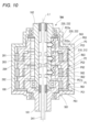
- FIG. 1 is a cross-sectional view of a power transmission device TM1 according to a first embodiment of the present invention.
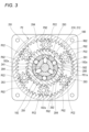
- 2 is a cross-sectional view taken along the line XX in FIG. 1.
- This is a cross-sectional view taken along the line YY in FIG.
- FIG. 11 is a cross-sectional view showing a state in which a first interrupting mechanism 210 has an interrupting portion 212 in an OFF state.
- FIG. 11 is a cross-sectional view showing a state in which a connecting/disconnecting unit 212 of a first connecting/disconnecting mechanism 210 is in an ON state.
- FIG. 1A and 1B are cross-sectional views showing the power transmission device TM1 in a neutral state, and FIG.
- FIG. 1C is a cross-sectional view showing the power transmission device TM1 in a high rotation state.
- FIG. 1C is a cross-sectional view showing the power transmission device TM1 in a high torque state.
- FIG. 4 is a cross-sectional view showing a power transmission device TM2 according to a second embodiment of the present invention.
- FIG. 11 is a cross-sectional view showing a power transmission device TM3 according to a third embodiment of the present invention.
- FIG. 11 is a cross-sectional view showing a power transmission device TM4 according to a fourth embodiment of the present invention.
- FIG. 13 is a cross-sectional view showing a power transmission device TM4 according to a modified example of the fourth embodiment of the present invention.
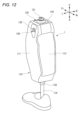
- FIG. 13 is a diagram showing a fifth embodiment of the present invention, and is a perspective view of an electric prosthetic leg 1 incorporating a power transmission device TM1.
- FIG. 13 is a side view of the electric prosthetic leg 1 of FIG. 12.
- FIG. 13 is a diagram showing the internal configuration of the electric prosthetic leg 1 in FIG. 12 .
- 1A to 1C are diagrams showing the movement of a user and the electric prosthetic leg 1 when ascending steps (ascending movement).
- 1A to 1C are diagrams illustrating the movement of a user and the electric prosthetic leg 1 when walking on flat ground (flat ground walking movement).
- FIG. 13 is a diagram showing a sixth embodiment of the present invention, illustrating the internal configuration of an electric prosthetic leg 1 incorporating a power transmission device TM1.
- FIG. 13 is a diagram showing a seventh embodiment of the present invention, illustrating the configuration of a moving body M1 in which a power transmission device TM1 is incorporated.
- the power transmission device TM1 includes a first shaft 181 and a second shaft 182 having the same rotation axis (hereinafter, rotation axis L1), an interrupting mechanism 20 and a transmission T provided on a power transmission path between the first shaft 181 and the second shaft 182, and a case 180 that accommodates them.
- the case 180 has a substantially cylindrical shape, and rotatably supports the first shaft 181 via a bearing 183, and rotatably supports the second shaft 182 via a bearing 184.
- the tip of the first shaft 181 is exposed from one end side (lower side in FIG.
- the first to sixth embodiments illustrate a case in which the power transmission devices TM1 to TM4 are arranged so that the rotation axis direction is in the up-down direction.
- the direction of the rotation axis will also be referred to as the up-down direction.
- the transmission T comprises a first power transmission path that transmits the power of a power source (not shown) input from a first shaft 181 to a second shaft 182 at a first gear ratio, and a second power transmission path that transmits the power to the second shaft 182 at a second gear ratio different from the first gear ratio.
- the transmission T includes a first planetary mechanism P1 and a second planetary mechanism P2.
- the first power transmission path includes the first planetary mechanism P1
- the second power transmission path includes the first planetary mechanism P1 and the second planetary mechanism P2.
- the interrupting mechanism 20 includes a first interrupting mechanism 210 and a second interrupting mechanism 220.
- the first interrupting mechanism 210 and the second interrupting mechanism 220 which will be described in detail later, switch between disconnecting and connecting the power in the first power transmission path, and also switch between disconnecting and connecting the power in the second power transmission path.
- the first planetary mechanism P1 and the second planetary mechanism P2 have sun gears SG1, SG2, ring gears RG1, RG2, a plurality of planetary gears PG1, PG2 that mesh with the sun gears SG1, SG2 and the ring gears RG1, RG2, and carriers PC1, PC2 that support the planetary gears PG1, PG2 so that they can rotate and revolve.
- the three rotating elements consisting of the sun gears SG1, SG2, the ring gears RG1, RG2, and the carriers PC1, PC2 satisfy a collinear relationship in which their rotational speeds are always aligned on a single straight line in a speed nomogram (also called a collinear diagram).
- the sun gears SG1, SG2 and carriers PC1, PC2 of the first planetary mechanism P1 and the second planetary mechanism P2 have the same rotation axis L1 as the first shaft 181 and the second shaft 182.
- the first planetary mechanism P1 and the second planetary mechanism P2 are arranged side by side in the rotation axis direction (up and down direction).
- the second planetary mechanism P2 is arranged outside the second shaft 182 and arranged so that at least a portion of it overlaps with the second shaft 182 when viewed in the radial direction.
- the first planetary mechanism P1 is arranged below the second planetary mechanism P2, and the first planetary mechanism P1 is also arranged outside the second shaft 182 and arranged so that at least a portion of it overlaps with the second shaft 182 when viewed in the radial direction.
- the sun gear SG1 of the first planetary mechanism P1 is formed integrally with the first shaft 181.
- the sun gear SG1 of the first planetary mechanism P1 does not necessarily have to be formed integrally with the first shaft 181, and may be connected separately from the first shaft 181 so as to be rotatable integrally with the first shaft 181. This allows the rotational power of the first shaft 181 to be input to the first planetary mechanism P1.
- the sun gear SG1 of the first planetary mechanism P1 is supported by the second shaft 182 via a bearing 185 arranged on the inside so as to be rotatable relative to the second shaft 182.
- the ring gear RG1 of the first planetary mechanism P1 is formed integrally with the case 180.
- the ring gear RG1 is non-rotatable.
- the ring gear RG1 of the first planetary mechanism P1 does not necessarily have to be formed integrally with the case 180, and may be separate from the case 180 and mechanically connected to the case 180 in a non-rotatable manner.
- the carrier PC1 of the first planetary mechanism P1 decelerates and outputs the rotation input from the sun gear SG1.
- the carrier PC1 of the first planetary mechanism P1 is formed integrally with the sun gear SG2 of the second planetary mechanism P2.
- the sun gear SG2 is formed on the outer periphery of the cylindrical portion PC1a that is formed integrally with the carrier PC1. This allows the rotational power that has been reduced in speed by the first planetary mechanism P1 to be transmitted to the second planetary mechanism P2.
- the sun gear SG2 (cylinder portion PC1a) of the second planetary mechanism P2 is connected to the second shaft 182 via the first interrupting mechanism 210. That is, in this embodiment, the first interrupting mechanism 210 is provided between the cylinder portion PC1a formed integrally with the carrier PC1 and the second shaft 182 located on the inner periphery of the cylinder portion PC1a. This forms a first power transmission path including the first planetary mechanism P1.
- the ring gear RG2 of the second planetary mechanism P2 is formed integrally with the case 180.
- the ring gear RG2 is non-rotatable.
- the ring gear RG2 of the second planetary mechanism P2 does not necessarily have to be formed integrally with the case 180, and may be separate from the case 180 and mechanically connected to the case 180 in a non-rotatable manner.
- the carrier PC2 of the second planetary mechanism P2 decelerates and outputs the rotation input from the sun gear SG2.
- the carrier PC2 of the second planetary mechanism P2 is connected to the second shaft 182 via the second interrupting mechanism 220.
- the second interrupting mechanism 220 is provided between the cylindrical portion PC2a formed integrally with the carrier PC2 and the second shaft 182 located on the inner periphery of the cylindrical portion PC2a.
- the cylindrical portion PC2a does not necessarily have to be formed integrally with the carrier PC2, and may be separate from the carrier PC2 and mechanically connected to the carrier PC2 so as to be rotatable integrally therewith.
- bearings that allow relative rotation may be provided between the rotating elements of the first planetary mechanism P1 and the rotating elements of the second planetary mechanism P2, and between the case 180 and the rotating elements of the first planetary mechanism P1 or the second planetary mechanism P2.
- a first power transmission path is formed that transmits the power of the power source input from the first shaft 181 to the second shaft 182 via the first planetary mechanism P1 and the first interrupting mechanism 210
- a second power transmission path is formed that transmits the power of the power source to the second shaft 182 via the first planetary mechanism P1, the second planetary mechanism P2, and the second interrupting mechanism 220.
- the first interrupting mechanism 210 includes an interrupting part 212 provided between the cylindrical part PC1a and the second shaft 182.
- the second interrupting mechanism 220 includes an interrupting part 222 provided between the cylindrical part PC2a and the second shaft 182. Details of the interrupting parts 212 and 222 are described below with reference to Figures 1 to 6.
- Each of the disconnecting parts 212, 222 has a common configuration and is configured to be switchable between a disconnected state in which the power transmission path is disconnected and a connected state in which the power transmission path is connected.
- Each of the disconnecting parts 212, 222 in this embodiment is configured using a two-way clutch 280 equipped with a forced free function.
- the two-way clutch 280 includes a plurality of rollers 281 (three in this embodiment) arranged between the outer peripheral surface of the second shaft 182 and the inner peripheral surface of the cylindrical portions PC1a and PC2a, a retainer 282 that holds the rollers 281 at a predetermined interval, an operating mechanism 240, a plurality of pins 283 (three in this embodiment) that penetrate the second shaft 182 in the radial direction and are operated by the operating mechanism 240 to a forced free position and a forced free release position, and a plurality of guides 284 (three in this embodiment) that are provided on the retainer 282 and determine the relative rotational position of the retainer 282 with respect to the second shaft 182 when the pins 283 are in the forced free position.
- the rollers 281 may be balls or sprags.
- the radial distance A between the outer peripheral surface of the second shaft 182 and the inner peripheral surface of the cylindrical portions PC1a and PC2a is smaller than the diameter B of the roller 281.
- flat portions 182a are formed at a predetermined interval in the circumferential direction on the outer peripheral portion of the second shaft 182, and the distance A is larger than the diameter B at the circumferential center side of the flat portions 182a.
- roller 281 when the roller 281 is held in the circumferential center of the flat portion 182a, the roller 281 does not mesh with the outer peripheral surface of the second shaft 182 or the inner peripheral surface of the cylindrical portions PC1a and PC2a (disengaged state), and relative rotation between the second shaft 182 and the cylindrical portions PC1a and PC2a is permitted (forced free state: see Figure 5).
- rollers 281 when the rollers 281 are allowed to move circumferentially relative to the second shaft 182, the rollers 281 mesh with the outer peripheral surface of the second shaft 182 and the inner peripheral surface of the cylindrical portions PC1a and PC2a (engaged state), and the second shaft 182 and the cylindrical portions PC1a and PC2a are connected so as to be able to rotate together in two directions (forced free release state: see Figure 6).
- the retainer 282 is ring-shaped and rotatable relative to the second shaft 182 and the cylindrical portions PC1a and PC2a, and has a number of roller holding portions 282a that hold the rollers 281 and a number of guide holding portions 282b that hold the guides 284.
- multiple rubber balls 282c are embedded at a predetermined interval in the circumferential direction on the outer peripheral surface of the retainer 282. These rubber balls 282c prevent unintended free rotation in the forced free release state by generating appropriate friction between the cylindrical portions PC1a, PC2a and the retainer 282. Note that the member that generates friction between the cylindrical portions PC1a, PC2a and the retainer 282 is not limited to the rubber balls 282c, and may be an O-ring.
- the pin 283 has a conical protrusion 283a at its radially outer end
- the guide 284 has a conical recess 284a at its radially inner end face that fits (engages) with the protrusion 283a.
- the operating mechanism 240 includes an operating rod 241 that is capable of operating the interrupting parts 212, 222 intermittently, and a servo motor 242 that moves the operating rod 241 linearly.
- the second shaft 182 is a hollow shaft that has an internal space S that extends in the direction of the rotation axis (also referred to as the up-down direction), and the operating rod 241 is disposed in this internal space S.
- small diameter portions 241b1, 241b2 and large diameter portions 241c1-241c3, which will be described later, are formed on the outer periphery of the operating rod 241 and abut against the inner diameter end (inner end) of the pin 283.
- the small diameter portions 241b1, 241b2 and large diameter portions 241c1-241c3 move the pin 283 forward and backward in the radial direction of the second shaft 182, or allow it to move forward and backward, thereby switching the state of the interrupted portions 212, 222.
- the outer periphery of the operating rod 241 is formed with a first large diameter portion 241c1, a first small diameter portion 241b1, a second large diameter portion 241c2, a second small diameter portion 241b2, and a third large diameter portion 241c3 at a predetermined length and intervals, in that order from the bottom.
- the operating rod 241 is provided so as to be able to simultaneously control the two interrupted portions 212, 222, but may be provided separately for each of the interrupted portions 212, 222.
- the interrupters 212 and 222 can be switched between a forced free state (hereinafter referred to as the OFF state) and a forced free release state (hereinafter referred to as the ON state) by the operating mechanism 240.
- a forced free state hereinafter referred to as the OFF state
- a forced free release state hereinafter referred to as the ON state
- the second large diameter portion 241c2 pushes the pin 283 of the interrupting portion 212 in the outward direction
- the third large diameter portion 241c3 pushes the pin 283 of the interrupting portion 222 in the outward direction, thereby turning the interrupting portion 222 and the interrupting portion 212 to the OFF state.
- the first power transmission path and the second power transmission path are cut off.
- the power transmission device TM1 is in a neutral state in which power transmission from the first shaft 181 to the second shaft 182 is cut off.
- the first small diameter portion 241b1 allows the pin 283 of the interrupting portion 212 to return in the inner diameter direction, while the third large diameter portion 241c3 pushes the pin 283 of the interrupting portion 222 in the outer diameter direction, thereby turning the interrupting portion 212 on and the interrupting portion 222 off.
- the first power transmission path is connected and the second power transmission path is disconnected.
- the power transmission device TM1 is in a high rotation state in which the rotational power of the first shaft 181 is decelerated through the first power transmission path (first planetary mechanism P1) and transmitted to the second shaft 182.
- the first large diameter portion 241c1 pushes the pin 283 of the interrupting portion 212 in the outer diameter direction while the second small diameter portion 241b2 allows the pin 283 of the interrupting portion 222 to return in the inner diameter direction, thereby turning the interrupting portion 212 to the OFF state and the interrupting portion 222 to the ON state.
- the first power transmission path is in the disconnected state and the second power transmission path is in the connected state.
- the power transmission device TM1 is in a high torque state in which the rotational power of the first shaft 181 is decelerated through the second power transmission path (first planetary mechanism P1 and second planetary mechanism P2) and transmitted to the second shaft 182.
- the roller 281 is an engaging element
- the operating rod 241, the pin 283, the guide 284, and the retainer 282 correspond to an operating part that operates the engaging element (roller 281) between an engaged state and a disengaged state.
- the guide 284 and the retainer 282 are actuators that move the engaging element (roller 281)
- the operating rod 241 and the pin 283 correspond to actuators that are provided to be able to operate the actuator.
- the actuator may be able to operate the engaging element (roller 281) without the actuator.
- the pin 283 is an advancing/retracting element that is provided to be able to move forward and backward along the radial direction
- the operating rod 241 corresponds to an extension portion that is provided to be able to move the advancing/retracting element (pin 283) forward and backward.
- the transmission T of the power transmission device TM1 can increase the gear ratio in a small space.
- the gear ratio can be effectively increased.
- the rotational axes of the carriers PC1, PC2 of the first planetary mechanism P1 and the second planetary mechanism P2 coincide with the rotational axes of the first shaft 181 and the second shaft 182, so the transmission T can be arranged coaxially with the first shaft 181 and the second shaft 182, making it possible to miniaturize the power transmission device TM1.
- the interrupting mechanism 20 also includes an operating rod 241 that is disposed in the internal space S of the second shaft 182 along the direction of the rotation axis, and disconnects and connects the first power transmission path and the second power transmission path based on the movement control of the operating rod 241. This allows the interrupting mechanism 20 to be concentrated inside the transmission T, further reducing the size of the power transmission device TM1.
- the first interrupting mechanism 210 is disposed downstream of the first planetary mechanism P1 in the first power transmission path
- the second interrupting mechanism 220 is disposed downstream of the first planetary mechanism P1 and the second planetary mechanism P2 in the second power transmission path. This makes it possible to reduce the number of members that rotate when power is input from the downstream side (second shaft 182).
- the power transmission device TM1 of the first embodiment includes two planetary mechanisms P1 and P2 as the transmission T and two on-off mechanisms 210 and 220 as the on-off mechanism 20, and switches between the neutral state, the high rotation state, and the high torque state based on the control of the on-off mechanisms 210 and 220.
- the power transmission device TM2 of the second embodiment includes one planetary mechanism P1 as the transmission T and one on-off mechanism 210 as the on-off mechanism 20, and differs from the power transmission device TM2 of the first embodiment in that it switches between the neutral state and the high rotation state based on the control of the on-off mechanism 210.
- the power transmission device TM2 can be configured smaller and more simply.
- the power transmission device TM3 of the third embodiment differs from the power transmission device TM1 of the first embodiment in that the second shaft 182 is an input shaft and the first shaft 181 is an output shaft.
- the sun gear SG1 of the first planetary mechanism P1 is connected to the second shaft 182 via a first interrupting mechanism 210.
- the carrier PC1 of the first planetary mechanism P1 is formed integrally with the sun gear SG2 of the second planetary mechanism P2.
- the sun gear SG2 of the second planetary mechanism P2 is connected to the second shaft 182 via a second interrupting mechanism 220, and the carrier PC2 is formed integrally with the first shaft 181.
- a neutral state is established in which the power transmission from the second shaft 182 to the first shaft 181 is interrupted.
- a high torque state is established in which the rotational power of the second shaft 182 is transmitted to the first shaft 181 via the first planetary mechanism P1 and the second planetary mechanism P2.
- a high rotation state is established in which the rotational power of the second shaft 182 is transmitted to the first shaft 181 via the second planetary mechanism P2.
- the power transmission device TM4 of the fourth embodiment has three planetary mechanisms P1, P2, and P3 as the transmission T, and three on-off mechanisms 210, 220, and 230 as the on-off mechanism 20, and differs from the power transmission device TM1 of the first embodiment in that it has a neutral state and three speed states (first speed state (high torque state), second speed state (medium rotation/medium torque state), and third speed state (high rotation state)).
- a third planetary mechanism P3 is disposed above the second planetary mechanism P2.
- the third planetary mechanism P3 has a sun gear SG3, a ring gear RG3, a plurality of planetary gears PG3 that mesh with the sun gear SG3 and the ring gear RG3, and a carrier PC3 that supports the planetary gear PG3 so that it can rotate and revolve around its axis.
- the three rotating elements consisting of the sun gear SG3, the ring gear RG3, and the carrier PC3 satisfy a collinear relationship in which their rotational speeds are always aligned on a single straight line in a speed nomogram (also called a collinear diagram).
- the carrier PC2 of the second planetary mechanism P2 is formed integrally with the sun gear SG3 of the third planetary mechanism P3.
- the sun gear SG3 is formed on the outer periphery of the cylindrical portion PC2a that is formed integrally with the carrier PC2. This allows the rotational power that has been reduced in speed by the second planetary mechanism P2 to be transmitted to the third planetary mechanism P3.
- the sun gear SG3 (cylinder portion PC2a) of the third planetary mechanism P3 is connected to the second shaft 182 via the second interrupter mechanism 220. This forms a second power transmission path including the first planetary mechanism P1 and the second planetary mechanism P2, similar to TM1 in the first embodiment.
- the ring gear RG3 of the third planetary mechanism P3 is formed integrally with the case 180.
- the ring gear RG3 is non-rotatable.
- the ring gear RG3 of the third planetary mechanism P3 does not necessarily have to be formed integrally with the case 180, and may be separate from the case 180 and fixed to the case 180 in a non-rotatable manner.
- the carrier PC3 of the third planetary mechanism P3 decelerates and outputs the rotation input from the sun gear SG3.
- the carrier PC3 of the third planetary mechanism P3 is connected to the second shaft 182 via a third interrupting mechanism 230.
- the third interrupting mechanism 230 is provided between the cylindrical portion PC3a formed integrally with the carrier PC3 and the second shaft 182 located on the inner periphery of the cylindrical portion PC3a.
- bearings that allow relative rotation may be provided between the rotating elements of the first planetary mechanism P1 and the rotating elements of the second planetary mechanism P2, between the rotating elements of the second planetary mechanism P2 and the rotating elements of the third planetary mechanism P3, and between the case 180 and the rotating elements of the first planetary mechanism P1, the second planetary mechanism P2, or the third planetary mechanism P3.
- a first power transmission path is formed that transmits the power of the power source input from the first shaft 181 to the second shaft 182 via the first planetary mechanism P1 and the first interrupting mechanism 210
- a second power transmission path is formed that transmits the power to the second shaft 182 via the first planetary mechanism P1, the second planetary mechanism P2, and the second interrupting mechanism 220
- a third power transmission path is formed that transmits the power to the second shaft 182 via the first planetary mechanism P1, the second planetary mechanism P2, the third planetary mechanism P3, and the third interrupting mechanism 230.
- the third interrupting mechanism 230 includes an interrupting portion 232 provided between the cylindrical portion PC3a and the second shaft 182.
- the configuration of the interrupting portion 232 is similar to that of the interrupting portions 212 and 222.
- the interrupting unit 212, the interrupting unit 222, and the interrupting unit 232 when the interrupting unit 212, the interrupting unit 222, and the interrupting unit 232 are turned off, the first to third power transmission paths are interrupted, and a neutral state is established in which the power transmission from the first shaft 181 to the second shaft 182 is interrupted.
- disconnector 212 when disconnector 212 is in the ON state and disconnector 222 and disconnector 232 are in the OFF state, the first power transmission path is connected, and the second power transmission path and the third power transmission path are disconnected, resulting in a third-speed state (high rotation state) in which the rotational power of the first shaft 181 is decelerated through the first power transmission path (first planetary mechanism P1) and transmitted to the second shaft 182.
- disconnector 222 when disconnector 222 is in the ON state and disconnector 212 and disconnector 232 are in the OFF state, the second power transmission path is connected, and the first power transmission path and the third power transmission path are disconnected, resulting in a second-speed state (medium rotation/medium torque state) in which the rotational power of the first shaft 181 is decelerated by the second power transmission path (first planetary mechanism P1 and second planetary mechanism P2) and transmitted to the second shaft 182.
- second-speed state medium rotation/medium torque state
- the third power transmission path is connected, the first power transmission path and the second power transmission path are disconnected, and a first speed state (high torque state) is established in which the rotational power of the first shaft 181 is decelerated by the third power transmission path (the first planetary mechanism P1, the second planetary mechanism P2, and the third planetary mechanism P3) and transmitted to the second shaft 182.
- the power transmission device TM4 of the fourth embodiment by adding a set of planetary mechanisms (the third planetary mechanism P3) and an interrupter mechanism (the third interrupter mechanism 230) to the power transmission device TM1 of the first embodiment, one gear can be added. Accordingly, the number of gears of the power transmission device TM4 may be four or more.
- the power transmission device TM4 of the modified example of the fourth embodiment has three planetary mechanisms P1, P2, P3 as the transmission T and three on-off mechanisms 210, 220, 230 as the on-off mechanism 20, and is the same as the power transmission device TM4 of the fourth embodiment in that it has a neutral state and three speed change states (first speed state (high torque state), second speed state (medium rotation/medium torque state), and third speed state (high rotation state)).
- the carrier PC1 of the first planetary mechanism P1 is formed integrally with the first shaft 181.
- the carrier PC1 of the first planetary mechanism P1 does not necessarily have to be formed integrally with the first shaft 181, and may be separate from the first shaft 181 and connected to the first shaft 181 so as to be rotatable integrally therewith. This allows the rotational power of the first shaft 181 to be input to the first planetary mechanism P1.
- the sun gear SG1 of the first planetary mechanism P1 is also formed integrally with the sun gear SG2 of the second planetary mechanism P2.
- the sun gear SG1 of the first planetary mechanism P1 does not necessarily have to be formed integrally with the sun gear SG2 of the second planetary mechanism P2, and may be separate from the sun gear SG2 of the second planetary mechanism P2 and connected to the sun gear SG2 of the second planetary mechanism P2 so as to be rotatable integrally therewith. This allows the rotational power accelerated by the first planetary mechanism P1 to be transmitted to the second planetary mechanism P2.
- bearings that allow relative rotation may be provided between the rotating elements of the first planetary mechanism P1 and the rotating elements of the second planetary mechanism P2, between the rotating elements of the second planetary mechanism P2 and the rotating elements of the third planetary mechanism P3, and between the case 180 and the rotating elements of the first planetary mechanism P1, the second planetary mechanism P2, or the third planetary mechanism P3.
- a first power transmission path is formed that transmits the power of the power source input from the first shaft 181 to the second shaft 182 via the first planetary mechanism P1 and the first interrupting mechanism 210
- a second power transmission path is formed that transmits the power to the second shaft 182 via the first planetary mechanism P1, the second planetary mechanism P2, and the second interrupting mechanism 220
- a third power transmission path is formed that transmits the power to the second shaft 182 via the first planetary mechanism P1, the second planetary mechanism P2, the third planetary mechanism P3, and the third interrupting mechanism 230.
- this modified transmission T it is possible to set it so that the rotation of the first shaft 181 is transmitted to the second shaft 182 at an increased speed in the first power transmission path, is transmitted to the second shaft 182 at a substantially constant speed in the second power transmission path, and is transmitted to the second shaft 182 at a reduced speed in the third power transmission path.
- an electric prosthetic leg 1 (fifth embodiment) incorporating the power transmission device TM1 of the first embodiment will be described with reference to Figures 12 to 16.
- the front-rear direction, left-right direction, and up-down direction are defined based on the user of the electric prosthetic leg 1.
- the front of the electric prosthetic leg is indicated as Fr, the rear as Rr, the left side as L, the right side as R, the upper side as U, and the lower side as D.
- the electric prosthetic leg 1 is a prosthetic leg that is attached to the leg of a person without a knee, and includes a below-knee member 110 located below the knee, an above-knee member 120 attached to the thigh and located above the knee, a knee joint mechanism 130 that connects the below-knee member 110 and the above-knee member 120 in a changeable manner, an expansion/contraction device 200 that can expand and contract the angle between the below-knee member 110 and the above-knee member 120, and a battery B that supplies power to the expansion/contraction device 200, etc.
- the above-knee member 120 comprises an adapter 121 that is connected to a socket (not shown), an upper wall portion 125 to which the adapter 121 is attached, and a pair of left and right side walls (not shown) that are connected to the upper wall portion 125.
- the socket is a joint member provided on the thigh portion 123 (see Figures 15 and 15), and by connecting the adapter 121 to the socket, the above-knee member 120 is integrated with the thigh portion 123.
- the knee-lower member 110 comprises a box-shaped main frame 111 that is open at the rear, a removable rear cover 113 that covers the rear opening of the main frame 111 in an openable and closable manner, and an adapter 122 attached to the underside of the main frame 111.
- the upper knee member 120 is attached to the upper part of the main frame 111 of the lower knee member 110 via a connecting shaft 135 that constitutes the knee joint mechanism 130, and the legs 114 extending downward are connected to the adapter 122 of the main frame 111.
- an expansion/contraction device 200 is provided that can expand and reduce the angle between the below-knee member 110 and the above-knee member 120.
- the expansion/contraction device 200 is configured to be able to expand and reduce the angle between the below-knee member 110 and the above-knee member 120 by meshing gears.
- the expansion/contraction device 200 includes a motor M that outputs rotational power, a power transmission device TM1 that transmits the power of the motor M, and a bevel gear mechanism 140 that can expand and reduce the angle between the below-knee member 110 and the above-knee member 120.
- Motor M is, for example, a permanent magnet type electric motor, and is disposed below power transmission device TM1.
- Motor M is a motor with a built-in gear mechanism, including a motor body 171, a gear mechanism 172 that reduces the output rotation of motor body 171, and an output shaft 170 that outputs the reduced rotational power.
- Output shaft 170 is a hollow cylindrical shaft with an internal space 170a aligned along the rotation axis.
- the bevel gear mechanism 140 has a first bevel gear 141 that is positioned on the opposite side of the motor M from the power transmission device TM1 on the power transmission path of the motor M and is supported by the below-knee member 110, and a second bevel gear 142 that is meshed with the first bevel gear 141 so as to be capable of transmitting rotation and is supported by the above-knee member 120.
- the first bevel gear 141 is configured to be rotatable integrally with the second shaft 182, which is the output element of the power transmission device TM1.
- the first bevel gear 141 transmits the power of the motor M transmitted via the power transmission device TM1 to the second bevel gear 142.
- the second bevel gear 142 is provided so as to be rotatable relative to the connecting shaft 135 and integrally rotate with the above-knee member 120.
- the power transmission device TM1 is arranged so that the rotation axis L1 of the first shaft 181 and the second shaft 182 coincides with the rotation axis L2 of the output shaft 170 of the motor M and the first bevel gear 141.
- the first shaft 181 is connected to the output shaft 170 of the motor M so as to be able to rotate together with the motor M, and inputs the rotational power of the motor M to the power transmission device TM1.
- the second shaft 182 is connected to the first bevel gear 141 so as to be able to rotate together with the motor M, and transmits the rotational power of the motor M, the speed of which has been changed by the power transmission device TM1, to the first bevel gear 141.
- the operating rod 241 extends below the motor M through the internal space 170a formed in the output shaft 170 of the motor M, and is controlled to move by the servo motor 242 provided below the motor M.
- the power transmission device TM1 has two power transmission paths with different gear ratios as described above, thereby switching the movement speed and generated power of the extension and flexion in the knee joint mechanism 130.
- FIG 15 is a diagram showing the movement of the user and the electric prosthetic leg 1 when ascending stairs (ascending movement).
- (A) to (D) show the stance phase
- (D) to (E) show the transition phase from stance to early swing
- (E) to (G) show the early swing phase
- (G) show the transition phase from early swing to late swing and the late swing phase
- (H) show the transition phase from late swing to stance and the stance phase.
- the power transmission device TM1 is in the high torque state shown in Figure 7 (C).
- the rotation of the first bevel gear 141 fixed to the below-knee member 110 causes the second bevel gear 142 fixed to the above-knee member 120 to rotate, causing the above-knee member 120 to rotate about the connecting shaft 135 relative to the below-knee member 110, and extending the knee joint mechanism 130.
- this extension power is a high-torque power, it is possible to reliably extend the knee joint mechanism 130 from a bent state even when a large load is placed on the electric prosthetic leg 1 when the electric prosthetic leg 1 is put forward to climb stairs.
- the knee joint mechanism 130 needs to be bent (raised) from an extended position while a load is being applied to the healthy leg, as shown in (E) to (H) of Figure 15.
- a large amount of power is not required, but quick movement is required.
- the power transmission device TM1 is in the high rotation state shown in Figure 7 (B).
- the rotation of the first bevel gear 141 fixed to the below-knee member 110 causes the second bevel gear 142 fixed to the above-knee member 120 to rotate, causing the above-knee member 120 to rotate about the connecting shaft 135 relative to the below-knee member 110, bending the knee joint mechanism 130.
- this bending power is a high-rotation power, it becomes possible to quickly bend the knee joint mechanism 130.
- Figure 16 shows the movement of the user and the powered prosthetic leg when walking on flat ground (flat ground walking movement).
- Figure 16 (A) to (D) show the stance phase, (D) shows the transition phase from stance to swing, (E) to (H) show the swing phase, and (H) shows the transition phase from swing to stance and the stance phase.
- the power transmission device TM1 When walking on flat ground as shown in Figure 16, and when descending stairs (stepping down), as shown in (A) to (D) of Figure 16, with a load applied to the electric prosthetic leg 1, the power transmission device TM1 is set to the high rotation state shown in (B) of Figure 7.
- the motor M When the motor M is set to a non-driven state in this state, the external force in the bending direction acting on the electric prosthetic leg 1 is transmitted from the bevel gear mechanism 140 to the motor M via the first planetary mechanism P1 of the power transmission device TM1, and by utilizing the friction of the motor M and the first planetary mechanism P1 to dampen the external force in the bending direction, so-called knee bending is prevented.
- the power transmission device TM1 when a load is applied to the healthy leg, the power transmission device TM1 is in the neutral state shown in (A) of Figure 7. In this state, the motor M and the bevel gear mechanism 140 are in a state where power transmission is disabled, so the user of the electric prosthetic leg 1 can swing out his or her leg smoothly.
- the electric prosthetic leg 1 shown in FIG. 17 is a modified example of the fifth embodiment, and differs from the fifth embodiment in that the electric prosthetic leg 1 is bent and extended using a spindle unit SP instead of the bevel gear mechanism 140.
- the spindle unit SP has a spindle 173 with a male thread and a sleeve 174 with a female thread, and the sleeve 174 translates along the rotation axis of the spindle 173 due to the rotation of the spindle 173.
- the spindle 173 performs a rotational motion by receiving the rotational power of the motor M transmitted by the power transmission device TM1.
- the sleeve 174 is supported by the knee lower side member 110 so as to be non-rotatable and movable up and down. Therefore, when the spindle 173 rotates to one side by receiving the rotational power of the motor M transmitted by the power transmission device TM1, the sleeve 174 translates away from the power transmission device TM1, and when the spindle 173 rotates to the other side, the sleeve 174 translates toward the power transmission device TM1.
- the translational movement of the sleeve 174 away from the power transmission device TM1 is sometimes referred to as the extension operation of the spindle unit SP, and conversely, the translational movement of the sleeve 174 toward the power transmission device TM1 is sometimes referred to as the contraction operation of the spindle unit SP.
- the distance between the sleeve 174 and the power transmission device TM1 expands and contracts depending on the rotation direction of the spindle 173.
- the upper end of the sleeve 174 is connected to the above-knee member 120 via a link member 175.
- the below-knee member 110 and the above-knee member 120 rotate around the connecting shaft 135. This changes the angle between the above-knee member 120 and the below-knee member 110.
- the knee joint mechanism 130 extends when the angle becomes larger, and the knee joint mechanism 130 bends when the angle becomes smaller.
- the sixth embodiment has the same action and effect as the fifth embodiment.
- the spindle unit SP and the power transmission device TM1 are arranged so that their rotation axes (rotation axis L1) coincide with each other.
- the motor M is arranged so that its rotation axis L2 is parallel to the rotation axis L1 of the spindle unit SP and the power transmission device TM1, and inputs rotational power to the power transmission device TM1 via the spur gear mechanism GM.
- Seventh Embodiment 18 shows the configuration of a moving body M1 incorporating the power transmission device TM1 of the first embodiment.
- the moving body M1 includes a motor M, a first gear 501 that outputs the rotational power of the motor M, a second gear 502 that is connected to a first shaft 181 of the power transmission device TM1 so as to be rotatable together with the first gear 501 and meshes with the first gear 501, a third gear 503 that is connected to a second shaft 182 of the power transmission device TM1 so as to be rotatable together with the second shaft 182 of the power transmission device TM1 and outputs the rotational power of the motor M whose speed has been changed by the power transmission device TM1, a fourth gear 504 that meshes with the third gear 503 and transmits the rotational power to the differential device DIF, left and right axles 505 to which the rotational power is transmitted from the differential device DIF so as to be rotatable differentially, and left and right wheels WH that
- the moving body M1 of the seventh embodiment can be shifted between a neutral state, a high rotation state, and a high torque state by the power transmission device TM1.
- a power transmission device including an interrupting mechanism (interrupting mechanism 20) and a transmission (transmission T),
- the interrupting mechanism (interrupting mechanism 20, first interrupting mechanism 210) is an engagement element (roller 281) disposed between the first rotating body (the cylinder portion PC1a) and the second rotating body (the second shaft 182); an operating portion (an operating rod 241, a pin 283, a retainer 282, a guide 284) that operates the engaging element between an engaged state in which the first rotating body and the second rotating body can rotate integrally and a disengaged state in which the first rotating body and the second rotating body can rotate relatively to each other;
- the operation unit includes: The actuator (retainer 282, guide 284) moves the engaging element, and an operating element (operating rod 241, pin 283) is provided so as to be able to operate the engaging element via the actuator or to be able to operate the engaging element without the actuator,
- the first rotating body and the second rotating body are arranged so that their rotation axes (rotation axis L1)
- the transmission can be concentrated around the second rotating body, making it possible to miniaturize the power transmission device.
- the inner end of the movable member abuts against the extension of the control member, allowing the movable member to move forward and backward along a direction perpendicular to the rotation axis of the first rotating body and the second rotating body.
- the rotor further includes a third rotor (cylinder portion PC2a) and a fourth rotor (second shaft 182) that are arranged so that their rotation axes coincide with the rotation axis of the third rotor (cylinder portion PC2a),
- the interrupting mechanism (interrupting mechanism 20, second interrupting mechanism 220) is Another engaging element (roller 281) disposed between the third rotating body and the fourth rotating body; an engagement state in which the third rotor and the fourth rotor can rotate together; the third rotating body and the fourth rotating body being in a disengaged state in which they are rotatable relative to one another, and further comprising other operating portions (operating rod 241, pin 283, retainer 282, guide 284) for operating the third rotating body and the fourth rotating body to a disengaged state in which the third rotating body and the fourth rotating body are rotatable relative to one another.
- the other operating portion includes another actuator (retainer 282, guide 284) that moves the other engaging element, and another operator (operation rod 241, pin 283) that is provided so as to be able to operate the other engagement element via the other actuator, or so as to be able to operate the other engagement element without via the other actuator.
- the other operating element includes another moving element (pin 283) that is movable forward and backward along a direction perpendicular to the rotation axis, and another extension portion (operation rod 241) extending along the rotation axis and movable back and forth along the rotation axis.
- the other reciprocating element can move back and forth along a direction perpendicular to the rotation axis of the third rotating body and the fourth rotating body.
- the power transmission device according to (5), The second rotor and the fourth rotor are provided so as to be integrally rotatable, a power transmission device in which the extension portion and the other extension portion are integrally provided and disposed at different positions in the direction of the rotation axis.
- the drive source for the second rotating body and the fourth rotating body can be shared, simplifying the control.
- the power transmission device according to (5) or (6),
- the other reciprocating element is provided so that an inner end, which is an end portion of the other reciprocating element on the rotation axis side in the radial direction, abuts against the other extending portion.
- the inner end of the other retractable element abuts against the other extension portion of the other operator, allowing the other retractable element to move forward and backward along a direction perpendicular to the rotation axis of the third rotating body and the fourth rotating body.
- the rotation changed in the transmission section is transmitted to the third rotating body.
- the power transmission device is Another first rotating element (sun gear SG1), another transmission unit (first planetary mechanism P1) including another second rotating element (carrier PC1) provided so as to be capable of transmitting rotation to the other first rotating element, and another third rotating element (ring gear RG1) provided so as to be capable of transmitting rotation to the other second rotating element, A power transmission device in which the other second rotating element of the other transmission unit is formed integrally with the first rotating element of the transmission unit, or is mechanically connected to the first rotating element of the transmission unit so as to rotate integrally with the first rotating element of the transmission unit.
- a power transmission device including an interrupting mechanism (interrupting mechanism 20) and a transmission (transmission T)
- the interrupting mechanism includes: an engagement element (roller 281) disposed between a first rotating body (sun gear SG2) and a second rotating body (second shaft 182); an operating portion (an operating rod 241, a pin 283, a retainer 282, a guide 284) that operates the engaging element between an engaged state in which the first rotating body and the second rotating body can rotate integrally and a disengaged state in which the first rotating body and the second rotating body can rotate relatively to each other;
- the operation unit includes: The actuator (retainer 282, guide 284) moves the engaging element, and an operating element (operating rod 241, pin 283) is provided so as to be able to operate the engaging element via the actuator or to be able to operate the engaging element without the actuator,
- the first rotating body and the second rotating body are arranged so that their rotation axes (rotation axis L1) coincide with each other and so that at least a
- the transmission can be arranged coaxially with the rotational axis of the first rotor and the second rotor, making it possible to miniaturize the power transmission device.
- the power transmission device (11) The power transmission device according to (10), The power of a power source (motor M) is input to the first rotating element of the planetary transmission unit,
- the power source includes an electric motor having a rotation axis (rotation axis L2) that coincides with the rotation axes of the first rotating body and the second rotating body, the power transmission device.
- the power source can also be arranged coaxially with the rotation axis of the first rotating body and the second rotating body.
- a first member (knee-lower member 110); A second member (above-knee member 120); a connecting portion (knee joint mechanism 130) that connects the first member and the second member in a manner that allows an angle between the first member and the second member to be changed;
- a joint device (electric prosthetic leg 1) including an expansion/contraction device (expansion/contraction device 200) capable of expanding and contracting the angle between the first member and the second member,
- the expansion/contraction device is a coupling device including a power transmission device (power transmission devices TM1 to TM3) described in any one of (1) to (10).
- a first member (knee-lower member 110); A second member (above-knee member 120); a connecting portion (knee joint mechanism 130) that connects the first member and the second member in a manner that allows an angle between the first member and the second member to be changed;
- a joint device (electric prosthetic leg 1) including an expansion/contraction device (expansion/contraction device 200) capable of expanding and contracting the angle between the first member and the second member,
- the expansion/contraction device is A power source (motor M) and a power transmission device (power transmission devices TM1 to TM4) that transmit the power of the power source,
- the power transmission device includes: a first power transmission path that transmits the power at a first gear ratio; a second power transmission path that transmits the power at a second speed ratio different from the first speed ratio,
- the expansion/contraction device is a first interrupting mechanism (first interrupting mechanism 210) that switches between interruption and connection of power in the first power transmission path; a second interrupting mechanism (second interrupt
- Each of the planetary transmission unit and the other planetary transmission unit has a planetary transmission unit (first planetary mechanism P1, second planetary mechanism P2) that is configured such that the rotational speeds of three rotational elements, which are a first rotational element (sun gears SG1, SG2), a second rotational element (carriers PC1, PC2), and a third rotational element (ring gears RG1, RG2), satisfy a collinear relationship in which the rotational speeds are aligned on a single straight line in a collinear diagram,
- a coupling device wherein the other second rotating element of the other planetary transmission unit is formed integrally with the first rotating element of the planetary transmission unit, or is mechanically connected to the first rotating element of the planetary transmission unit so as to be integrally rotatable with the first rotating element of the planetary transmission unit.
- the rotation changed in speed by another planetary transmission unit can be transmitted to the planetary transmission unit.
- the first interrupting mechanism is disposed downstream of the planetary transmission unit in the first power transmission path, a coupling device, wherein the second interrupting mechanism is disposed downstream of the planetary speed change unit and the another planetary speed change unit in the second power transmission path.
- the first and second power transmission paths can be appropriately switched.
- Electric prosthetic limb (joint device) 20 Intermittent mechanism 110 Knee lower member (first member) 120 Knee-upper member (second member) 130 Knee joint mechanism (joint part) 182 second shaft (second rotating body, fourth rotating body) 200 Expanding/contracting device 210 First interrupting mechanism (interrupting mechanism) 220 Second interruption mechanism (interruption mechanism) 241 Operating rod (extension part, other extension part, operator, other operator, operating part) 281 Roller (engager) 282 Retainer (operator, other actuator, operating part) 283 pin (advance/retraction device, other advance/retraction device, operator, other operator, operation unit) 284 Guide (actuator, other actuator, operating part) TM1 to TM4 Power transmission device P1 First planetary mechanism (other transmission parts, other planetary transmission parts) P2 Second planetary mechanism (transmission section, planetary transmission section) SG1 Sun gear (other first rotating element) SG2 Sun gear (first rotating element) RG1 Ring gear (other third rotating element) RG2 Ring gear (
Landscapes
- Engineering & Computer Science (AREA)
- General Engineering & Computer Science (AREA)
- Health & Medical Sciences (AREA)
- Mechanical Engineering (AREA)
- Transplantation (AREA)
- Biomedical Technology (AREA)
- General Health & Medical Sciences (AREA)
- Cardiology (AREA)
- Oral & Maxillofacial Surgery (AREA)
- Veterinary Medicine (AREA)
- Public Health (AREA)
- Heart & Thoracic Surgery (AREA)
- Vascular Medicine (AREA)
- Life Sciences & Earth Sciences (AREA)
- Animal Behavior & Ethology (AREA)
- Transportation (AREA)
- Chemical & Material Sciences (AREA)
- Combustion & Propulsion (AREA)
- Orthopedic Medicine & Surgery (AREA)
- Transmission Devices (AREA)
Priority Applications (3)
| Application Number | Priority Date | Filing Date | Title |
|---|---|---|---|
| EP24780711.8A EP4671556A1 (en) | 2023-03-31 | 2024-03-28 | POWER TRANSMISSION DEVICE AND SEAL DEVICE |
| CN202480022116.7A CN121002299A (zh) | 2023-03-31 | 2024-03-28 | 动力传递装置及接头装置 |
| JP2025511203A JPWO2024204612A1 (https=) | 2023-03-31 | 2024-03-28 |
Applications Claiming Priority (2)
| Application Number | Priority Date | Filing Date | Title |
|---|---|---|---|
| JP2023-058069 | 2023-03-31 | ||
| JP2023058069 | 2023-03-31 |
Publications (1)
| Publication Number | Publication Date |
|---|---|
| WO2024204612A1 true WO2024204612A1 (ja) | 2024-10-03 |
Family
ID=92906733
Family Applications (1)
| Application Number | Title | Priority Date | Filing Date |
|---|---|---|---|
| PCT/JP2024/012822 Ceased WO2024204612A1 (ja) | 2023-03-31 | 2024-03-28 | 動力伝達装置及び継手装置 |
Country Status (4)
| Country | Link |
|---|---|
| EP (1) | EP4671556A1 (https=) |
| JP (1) | JPWO2024204612A1 (https=) |
| CN (1) | CN121002299A (https=) |
| WO (1) | WO2024204612A1 (https=) |
Citations (7)
| Publication number | Priority date | Publication date | Assignee | Title |
|---|---|---|---|---|
| US20140291099A1 (en) * | 2013-03-26 | 2014-10-02 | Schaeffler Technologies AG & Co. KG | Switchable bi-directional wedge clutch |
| DE102016002592A1 (de) * | 2016-03-03 | 2017-09-07 | Man Truck & Bus Ag | Modulare 1- oder 2-Gang-Getriebevorrichtung für ein Elektrofahrzeug |
| JP2019217880A (ja) * | 2018-06-19 | 2019-12-26 | 日本精工株式会社 | 連結装置 |
| WO2021251500A1 (ja) | 2020-06-12 | 2021-12-16 | 本田技研工業株式会社 | 継手装置 |
| DE102020125984A1 (de) * | 2020-10-05 | 2022-04-07 | Schaeffler Technologies AG & Co. KG | Antriebsvorrichtung für ein Kraftfahrzeug |
| WO2022260098A1 (ja) * | 2021-06-11 | 2022-12-15 | 本田技研工業株式会社 | 継手装置 |
| JP2023058069A (ja) | 2021-10-13 | 2023-04-25 | パナソニックIpマネジメント株式会社 | 冷蔵庫 |
-
2024
- 2024-03-28 WO PCT/JP2024/012822 patent/WO2024204612A1/ja not_active Ceased
- 2024-03-28 EP EP24780711.8A patent/EP4671556A1/en active Pending
- 2024-03-28 CN CN202480022116.7A patent/CN121002299A/zh active Pending
- 2024-03-28 JP JP2025511203A patent/JPWO2024204612A1/ja active Pending
Patent Citations (7)
| Publication number | Priority date | Publication date | Assignee | Title |
|---|---|---|---|---|
| US20140291099A1 (en) * | 2013-03-26 | 2014-10-02 | Schaeffler Technologies AG & Co. KG | Switchable bi-directional wedge clutch |
| DE102016002592A1 (de) * | 2016-03-03 | 2017-09-07 | Man Truck & Bus Ag | Modulare 1- oder 2-Gang-Getriebevorrichtung für ein Elektrofahrzeug |
| JP2019217880A (ja) * | 2018-06-19 | 2019-12-26 | 日本精工株式会社 | 連結装置 |
| WO2021251500A1 (ja) | 2020-06-12 | 2021-12-16 | 本田技研工業株式会社 | 継手装置 |
| DE102020125984A1 (de) * | 2020-10-05 | 2022-04-07 | Schaeffler Technologies AG & Co. KG | Antriebsvorrichtung für ein Kraftfahrzeug |
| WO2022260098A1 (ja) * | 2021-06-11 | 2022-12-15 | 本田技研工業株式会社 | 継手装置 |
| JP2023058069A (ja) | 2021-10-13 | 2023-04-25 | パナソニックIpマネジメント株式会社 | 冷蔵庫 |
Non-Patent Citations (1)
| Title |
|---|
| See also references of EP4671556A1 |
Also Published As
| Publication number | Publication date |
|---|---|
| JPWO2024204612A1 (https=) | 2024-10-03 |
| CN121002299A (zh) | 2025-11-21 |
| EP4671556A1 (en) | 2025-12-31 |
Similar Documents
| Publication | Publication Date | Title |
|---|---|---|
| JP7705855B2 (ja) | 継手装置 | |
| JP7497360B2 (ja) | 継手装置 | |
| JP5525751B2 (ja) | 歩行ロボット | |
| WO2022260098A1 (ja) | 継手装置 | |
| JP7604682B2 (ja) | 動力伝達装置 | |
| JP4812756B2 (ja) | 摺動噛み合いクラッチ装置によって制御される、自動車用の2動作モードを有する動力分岐無限可変トランスミッション | |
| JP2017013157A (ja) | 脚部又は腕部動作支援式ウエアラブルロボット | |
| WO2024204612A1 (ja) | 動力伝達装置及び継手装置 | |
| WO2024135748A1 (ja) | 継手装置 | |
| WO2024204613A1 (ja) | 継手装置及び駆動装置 | |
| JP7830109B2 (ja) | 断続装置 | |
| JP2024179347A (ja) | 動力伝達装置 | |
| JP7851717B2 (ja) | 断続装置 | |
| JP7674857B2 (ja) | 継手装置 | |
| JP2023144954A (ja) | 断続装置 | |
| JP7830110B2 (ja) | 動力伝達装置 | |
| JP2026064501A (ja) | 動力伝達装置 | |
| JP2024179342A (ja) | 断続装置 | |
| JP2026064502A (ja) | 動力伝達装置 | |
| JP7734210B2 (ja) | 断続装置 | |
| JP2025142529A (ja) | 断続装置 | |
| JP2023088643A (ja) | 動力伝達装置 | |
| JP7835312B2 (ja) | 車両用変速機 | |
| US20250049587A1 (en) | Interrupting device and coupling device | |
| JP2022133997A (ja) | 継手装置 |
Legal Events
| Date | Code | Title | Description |
|---|---|---|---|
| 121 | Ep: the epo has been informed by wipo that ep was designated in this application |
Ref document number: 24780711 Country of ref document: EP Kind code of ref document: A1 |
|
| ENP | Entry into the national phase |
Ref document number: 2025511203 Country of ref document: JP Kind code of ref document: A |
|
| WWE | Wipo information: entry into national phase |
Ref document number: 2025511203 Country of ref document: JP Ref document number: 2024780711 Country of ref document: EP |
|
| NENP | Non-entry into the national phase |
Ref country code: DE |
|
| ENP | Entry into the national phase |
Ref document number: 2024780711 Country of ref document: EP Effective date: 20250926 |
|
| ENP | Entry into the national phase |
Ref document number: 2024780711 Country of ref document: EP Effective date: 20250926 |
|
| WWP | Wipo information: published in national office |
Ref document number: 2024780711 Country of ref document: EP |