WO2024204423A1 - 流路デバイスおよび検知装置 - Google Patents
流路デバイスおよび検知装置 Download PDFInfo
- Publication number
- WO2024204423A1 WO2024204423A1 PCT/JP2024/012405 JP2024012405W WO2024204423A1 WO 2024204423 A1 WO2024204423 A1 WO 2024204423A1 JP 2024012405 W JP2024012405 W JP 2024012405W WO 2024204423 A1 WO2024204423 A1 WO 2024204423A1
- Authority
- WO
- WIPO (PCT)
- Prior art keywords
- groove
- corner
- pair
- main surfaces
- flow path
- Prior art date
- Legal status (The legal status is an assumption and is not a legal conclusion. Google has not performed a legal analysis and makes no representation as to the accuracy of the status listed.)
- Ceased
Links
Images











Classifications
-
- B—PERFORMING OPERATIONS; TRANSPORTING
- B01—PHYSICAL OR CHEMICAL PROCESSES OR APPARATUS IN GENERAL
- B01J—CHEMICAL OR PHYSICAL PROCESSES, e.g. CATALYSIS OR COLLOID CHEMISTRY; THEIR RELEVANT APPARATUS
- B01J19/00—Chemical, physical or physico-chemical processes in general; Their relevant apparatus
-
- G—PHYSICS
- G01—MEASURING; TESTING
- G01N—INVESTIGATING OR ANALYSING MATERIALS BY DETERMINING THEIR CHEMICAL OR PHYSICAL PROPERTIES
- G01N35/00—Automatic analysis not limited to methods or materials provided for in any single one of groups G01N1/00 - G01N33/00; Handling materials therefor
- G01N35/08—Automatic analysis not limited to methods or materials provided for in any single one of groups G01N1/00 - G01N33/00; Handling materials therefor using a stream of discrete samples flowing along a tube system, e.g. flow injection analysis
-
- G—PHYSICS
- G01—MEASURING; TESTING
- G01N—INVESTIGATING OR ANALYSING MATERIALS BY DETERMINING THEIR CHEMICAL OR PHYSICAL PROPERTIES
- G01N37/00—Details not covered by any other group of this subclass
Definitions
- This disclosure relates to a flow path device and a detection apparatus.
- a flow path device that includes a first member having a groove that serves as a flow path and a second member joined to the first member (see, for example, Patent Document 1).
- a flow path device comprises a first member having a pair of first main surfaces and having a groove including an opening located on one of the pair of first main surfaces, and a second member having a pair of second main surfaces, one of the pair of second main surfaces being joined to one side of the pair of first main surfaces of the first member so as to close the opening, and the first member or the second member has a through hole connected to the groove, and when viewed in a plan view, a corner is formed on the edge of the groove, and no corner is formed on the edge of the groove opposite the corner.
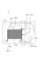
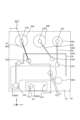
- FIG. 1 is a top view of a detection device according to a first embodiment.
- FIG. 2 is a side view of the detection device according to the first embodiment.
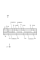
- FIG. 3 is a plan view of the separation channel device according to the first embodiment.
- FIG. 4 is a cross-sectional view taken along line BB shown in FIG.
- FIG. 5 is an enlarged plan view of region I shown in FIG. 3.
- FIG. 6 is a plan view of the separation channel device according to the first embodiment.
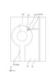
- FIG. 7 is an enlarged plan view of region II shown in FIG. 6.
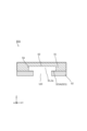
- FIG. 8 is a cross-sectional view taken along line CC shown in FIG.
- FIG. 9 is a cross-sectional view taken along line DD shown in FIG. FIG.
- FIG. 10 is a diagram showing another example of the configuration of the corner portion and the first relief groove according to the first embodiment, in a plan view.
- FIG. 11 is a plan view of the base flow path device according to the first embodiment.
- FIG. 12 is a cross-sectional view taken along line EE shown in FIG.
- FIG. 13 is a plan view of the detection device according to the first embodiment.
- FIG. 14A is a plan view of only the first member shown in FIG. 13.
- FIG. 14B is a plan view of only the second member shown in FIG. 13.
- FIG. 14C is a plan view of only the third member shown in FIG. 13.
- FIG. FIG. 15 is a cross-sectional view taken along the line FF shown in FIG. FIG.
- FIG. 16 is a plan view of the separation channel device according to the second embodiment.
- FIG. 17 is an enlarged plan view of the region III shown in FIG. 16.
- FIG. 18 is a cross-sectional view taken along line GG shown in FIG.
- FIG. 19 is a diagram showing another example of the configuration of the corner portion according to the second embodiment, in a plan view.
- FIG. 20 is a plan view of the detection device according to the second embodiment.
- FIG. 21 is a cross-sectional view taken along line HH shown in FIG.
- FIG. 22 is a plan view of a portion of the separation channel device according to the third embodiment.
- FIG. 23 is a cross-sectional view taken along the line JJ shown in FIG.
- FIG. 24 is a plan view showing another example of the configuration of the recess according to the third embodiment.
- a flow path device and a detection apparatus according to an embodiment of the present invention will be described with reference to the drawings.
- a Cartesian coordinate system (X, Y, Z) is defined, with the positive side in the Z direction being the top and the negative side in the Z direction being the bottom.
- a plan view refers to a view from the positive side in the Z direction.
- Fig. 1 is a top view of the detection device 10.
- Fig. 2 is a side view of the detection device 10 as viewed from the direction A in Fig. 1.
- the detection device 10 can separate specific particles in a fluid and collect the separated particles.
- the separation flow path device 3 according to this embodiment can separate white blood cells as specific particles from blood as a fluid and collect the white blood cells.
- the detection device 10 has a flow path device 1 and a detection unit 2. Furthermore, the flow path device 1 has a separation flow path device 3 and a base flow path device 4.
- the separation flow path device 3 has a first member 31 and a second member 32.
- the base flow path device 4 has a third member 41 and a fourth member 42.
- the flow path device 1 has a flow path 5 in each of the separation flow path device 3 and the base flow path device 4, and a fluid flows through the flow path 5.
- the separation flow path device 3 has a flow path 5 for separating and extracting specific particles from a fluid and sorting them.
- the base flow path device 4 has supply units 50A, 50B, and 50C for introducing a fluid into the flow path 5.
- the base flow path device 4 has a flow path 5 for supplying the fluid flowing in from the supply units 50A, 50B, and 50C to the separation flow path device 3, and a flow path 5 for collecting the fluid flowing in from the separation flow path device 3.
- the detection unit 2 in this embodiment is an optical sensor equipped with a light-emitting element and a light-receiving element.
- the detection unit 2 is disposed on the negative side of the Z axis of the flow path device 1.
- the detection unit 2 can detect leakage of the fluid flowing in the flow path 5.
- the flow path device 1 has a reservoir 50D for collecting fluid containing separated specific particles.
- the reservoir 50D is formed by the first member 31, the second member 32, and the third member 41 each having a through hole opening on the top and bottom surfaces, and a recess opening on the top surface of the fourth member 42.
- the depth of the reservoir 50D is the sum of the thickness of the first member 31, the thickness of the second member 32, the thickness of the third member 41, and the depth of the recess formed in the fourth member 42.
- the fluid containing the separated specific particles that has collected in the reservoir 50D is recovered, for example, using a suction device such as a syringe.
- the recovered fluid can be analyzed, for example, by performing concentration measurements, optical measurements, etc.
- the recovered fluid can also be used, for example, as a sample in experiments such as chemical reactions.
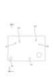
- Figure 3 is a plan view of the separation flow path device 3.
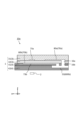
- Figure 4 is a cross-sectional view of the separation flow path device 3 cut along line B-B shown in Figure 3. Note that Figure 3 illustrates the separation flow path device 3 in a planar perspective view.
- the first member 31 is, for example, a flat member.
- the first member 31 has a pair of first main surfaces 311 as upper and lower surfaces.
- the first main surface 311 located in the positive direction of the Z axis is the other of the pair of first main surfaces 311B, and the first main surface 311 located in the negative direction of the Z axis is one of the pair of first main surfaces 311A.
- the first member 31 has a first groove 6a, and the first groove 6a has an opening 61a located in one of the pair of first main surfaces 311A.
- the first member 31 also has a first escape groove 7a, and the first escape groove 7a has an opening 71a located in one of the pair of first main surfaces 311A.
- the second member 32 is, for example, a flat plate-like member.
- the second member 32 has a pair of second main surfaces 321 as upper and lower surfaces.
- the second main surface 321 located in the positive direction of the Z axis is one of the pair of second main surfaces 321A
- the second main surface 321 located in the negative direction of the Z axis is the other of the pair of second main surfaces 321B.
- the second member 32 has one 321A of a pair of second main surfaces joined to one 311A of a pair of first main surfaces of the first member 31.
- the second member 32 is joined so as to block the opening 61a of the first groove 6a of the first member 31.
- the second member 32 is also joined so as to block the opening 71a of the first escape groove 7a of the first member 31.
- the first groove 6a including the opening 61a in the first member 31 is configured as the first flow path 5a
- the first escape groove 7a including the opening 71a in the first member 31 is configured as the first escape flow path 8a.
- the first escape flow path 8a does not allow fluid to flow in from outside the flow path device 1. In other words, when the flow path device 1 is in use, such as when separating white blood cells from blood, no fluid flows through the first escape flow path 8a unless a leak occurs from the first flow path 5a.
- the first flow path 5a in the separation flow path device 3 is composed of flow paths 5A, 5B, 5C, 5D, 5E, a pressing flow path 51, and a branch flow path 52.
- a first fluid containing specific particles to be separated flows through flow path 5A.
- the first fluid is blood, and the specific particles are white blood cells.
- a second fluid flows through flow path 5B for pressing the first fluid from the pressing flow path 51 to the branch flow path 52.
- the second fluid is saline.
- flow path 5C as in flow path 5B, a second fluid flows for pressing the first fluid from the pressing flow path 51 to the branch flow path 52.
- the first fluid flows from flow path 5A, and the second fluid flows from flow paths 5B and 5C into the pressing flow path 51.
- the third fluid containing particles different from the specific particles flows from the pressing flow path 51 to the branch flow path 52, the fourth fluid containing the specific particles flows to flow path 5D, and the other fifth fluid flows directly through the pressing flow path 51.
- Flow path 5D is connected to a reservoir 50D, and the fourth fluid containing the specific particles collects in reservoir 50D.
- the third fluid containing particles different from the specific particles flows from the multiple branch flow paths 52 into flow path 5E.
- the width of the first groove 6a may be, for example, 30 ⁇ m or more and 4000 ⁇ m or less.
- the depth of the first groove 6a may be, for example, 10 ⁇ m or more and 1000 ⁇ m or less.
- the width of the first escape groove 7a may be, for example, 20 ⁇ m or more and 1000 ⁇ m or less.
- the depth of the first escape groove 7a may be, for example, 5 ⁇ m or more and 500 ⁇ m or less.
- the first groove 6a and the first escape groove 7a can be formed by using conventionally known techniques such as casting, etching, and laser processing.
- the width and depth of the first groove 6a and the first escape groove 7a are the same as the width and height of the first flow path 5a and the first escape flow path 8a, respectively.
- the first member 31 and the second member 32 may be bonded, for example, via an adhesive, plasma bonded, or optically bonded.
- an adhesive for example, a UV-curable adhesive or a heat-curable adhesive may be used.
- plasma bonding for example, oxygen plasma is applied.
- optically bonding for example, ultraviolet light from an excimer lamp is applied.
- the material of the first member 31 may be, for example, PDMS (polydimethylsiloxane) or PMMA (polymethylmethacrylate: acrylic) resin, glass, polycarbonate resin, or the like.
- the material of the first member 31 according to this embodiment is PDMS.
- the thickness of the first member 31 may be, for example, 1 mm or more and 5 mm or less.
- the material of the second member 32 may be, for example, silicone, PDMS (polydimethylsiloxane) resin, PMMA (polymethylmethacrylate: acrylic) resin, glass, polycarbonate resin, or the like.
- the material of the second member 32 according to this embodiment is silicone, and in particular, silicone rubber.
- the thickness of the second member 32 may be, for example, 0.5 mm or more and 4 mm or less. Note that the thickness of the second member 32 according to this embodiment is smaller than the thickness of the first member 31.
- the first member 31 and the second member 32 may have, for example, a length along the Y-axis direction of 10 to 50 mm and a length along the X-axis direction of 10 to 30 mm.
- FIG. 5 is an enlarged view of region I shown in FIG. 3, as viewed from above. Note that FIG. 5 illustrates the separation channel device 3 in a perspective view from above.
- particle 9A a particle different from particle 9A
- particle 9B a particle different from particle 9A
- the separation flow channel device 3 by adjusting the cross-sectional area and length of each of the pressing flow channel 51 and the branch flow channel 52, and the flow speeds of the first and second fluids, it is possible to generate a "pull-in flow” in the pressing flow channel 51 that flows from the pressing flow channel 51 to the branch flow channel 52.
- the first region A1 shown by hatching indicates the "pull-in flow”.
- a "pushing flow” that can push the first fluid against the branch flow channel 52 by the second fluid is generated in the pressing flow channel 51.
- the particle 9B can be drawn into the branch flow path 52. Also, by making the width of the drawn-in flow flowing through the branch flow path 52 side of the pressing flow path 51 larger than the center of gravity of the particle 9B flowing through the first fluid and smaller than the center of gravity of the particle 9B, the particle 9B can be effectively drawn into the branch flow path 52. As a result, the particle 9A of the first fluid can be separated and made to flow from the pressing flow path 51 into the flow path 5D, thereby recovering the fourth fluid containing the particle 9A.
- the particle 9B can be separated from the first fluid and made to flow from the branch flow path 52 into the flow path 5E, thereby recovering the third fluid containing the particle 9B.
- the branch flow path 52 is designed so that the particle 9B flows into it by branching, but it is not necessarily the case that only the particle 9B flows into it. In other words, particles other than the particle 9B may flow into the branch flow path 52.
- the separation flow channel device 3 is intended to separate red blood cells and white blood cells in blood.
- the position of the center of gravity of red blood cells in blood is, for example, 2 to 2.5 ⁇ m from the edge, and the position of the center of gravity of white blood cells is, for example, 5 to 10 ⁇ m from the edge.
- the pushing flow channel 51 may have, for example, a cross-sectional area of 300 ⁇ m2 or more and 1000 ⁇ m2 or less and a length of 0.5 mm or more and 20 mm or less.
- the branching flow channel 52 may have, for example, a cross-sectional area of 100 ⁇ m2 or more and 500 ⁇ m2 or less and a length of 3 mm or more and 25 mm or less.
- the flow velocity in the pushing flow channel 51 may be, for example, 0.2 m/s or more and 5 m/s or less.
- the width of the drawing flow can be set to, for example, 2 ⁇ m or more and 15 ⁇ m or less, and red blood cells and white blood cells can be separated from blood.
- Figure 6 is a plan view of the separation flow path device 3, similar to Figure 3.
- Figure 7 is an enlarged plan view of region II shown in Figure 6.
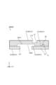
- Figure 8 is a cross-sectional view of the separation flow path device 3 cut along line C-C shown in Figure 7.
- Figure 9 is a cross-sectional view of the separation flow path device 3 cut along line D-D shown in Figure 7. Note that Figures 6 and 7 show the separation flow path device 3 as seen through a plan view.
- the second member 32 has through holes 12A, 12B, 12C, 12E, and 121 connected to the first groove 6a.
- the through holes 12A, 12B, 12C, 12E, and 121 are connected to the flow paths 5A, 5B, 5C, and 5E, respectively, and to the first groove 6a that constitutes the pressing flow path 51.
- the through holes 12A, 12B, 12C, 12E, and 121 connected to the first groove 6a are provided in the second member 32, but may be provided in the first member 31.
- Through hole 12A functions as an inlet for the first fluid to flow into flow path 5A.
- Through holes 12B and 12C function as inlets for the second fluid to flow into flow paths 5B and 5C, respectively.
- Through hole 12E functions as an outlet for the third fluid to flow out of flow path 5E.
- Through hole 121 functions as an outlet for the fifth fluid to flow out of pressing flow path 51.
- a pushing force acts on bottom wall 62 in the inner wall of first groove 6a in first member 31 in the opposite direction to the direction in which second member 32 is located, and a pushing force acts on one side 321A of the second main surface of second member 32 in the opposite direction to the direction in which first member 31 is located. This may cause the first member 31 and the second member 32, which were joined by a surface at one side 311A of the first main surface of the first member 31 and one side 321A of the second main surface of the second member 32, to peel off.
- corners 11 are formed on the edges of the first grooves 6a constituting the flow channels 5A, 5B, and 5C, and corners 11 are not formed on the edges of the first grooves 6a that face the corners 11.
- a "corner” is a triangular region formed by two half lines that form a corner 111 when viewed in a plan view.
- the third region A3 shown in gray indicates the corner 11.
- “facing” means facing when the first groove 6a is viewed in the width direction.
- the corner 11 is located on the negative side of the first groove 6a on the Y axis, and therefore the edge of the first groove 6a that faces the corner 11 refers to the edge of the first groove 6a that is located on the positive side of the Y axis.
- the corner 11 is located on the positive side of the Y axis of the first groove 6a, so the edge of the first groove 6a that faces the corner 11 refers to the edge of the first groove 6a that faces the negative side of the Y axis from the corner 11.
- the fourth region A4 shown by hatching indicates the opposing region.
- the corners 11 are formed on the edges of the first grooves 6a constituting the flow paths 5A, 5B, and 5C, and the corners 11 are not formed on the edges of the first grooves 6a opposite the corners 11. This causes the balance of the stress applied to the edges of the first grooves 6a by the first fluid or the second fluid to be lost. Specifically, the stress applied to the corners 11 is greater than the stress applied to the edges of the first grooves 6a opposite the corners 11. For this reason, stress is concentrated in the corners 111 in particular, and the first member 31 and the second member 32 are likely to peel off from the corners 111.
- the corners 11 are intentionally formed on the edges of the first grooves 6a constituting the flow paths 5A, 5B, and 5C, so that if the first member 31 and the second member 32 peel off from each other, the peeling is likely to occur from the corners 111. Therefore, leakage of the first or second fluid can be reliably detected by monitoring only the periphery of the corner 11, without monitoring the entire periphery of the first groove 6a in the flow path device 1. Therefore, in the flow path device 1 according to this embodiment, measures against leakage of the first or second fluid can be quickly taken.
- the corners 11 may be provided on the edge of the first groove 6a constituting the flow channel 5E or the edge of the first groove 6a constituting the pressing flow channel 51.
- the flow channels 5A, 5B, and 5C are located upstream of the flow channel 5E and the pressing flow channel 51 in the first flow channel 5a of the separation flow channel device 3. Therefore, the first fluid flowing through the flow channel 5A and the second fluid flowing through the flow channels 5B and 5C are subjected to a higher pressure on the inner wall of the first groove 6a and the one side 321A of the second main surface than the third fluid flowing through the flow channel 5E and the fifth fluid flowing through the pressing flow channel 51.
- the so-called fluid leakage is highly likely to occur in the flow channels 5A, 5B, and 5C, so the corners 11 are formed only on the edges of the first grooves 6a constituting the flow channels 5A, 5B, and 5C.
- the first groove 6a has a circular first planar portion 30 including the through holes 12A, 12B, 12C, 12E, and 121, and a band-shaped second planar portion 40 connected to the first planar portion 30.
- the first planar portion 30 is a circular portion of the first groove 6a including the through holes 12A, 12B, 12C, 12E, and 121.
- the first planar portion 30 of the first groove 6a constituting the flow path 5A is a portion into which the first fluid flows in the thickness direction through the through hole 12A.
- the first planar portion 30 of the first groove 6a constituting the flow paths 5B and 5C is a portion into which the second fluid flows in the thickness direction through the through holes 12B and 12C, respectively.
- the first planar portion 30 of the first groove 6a constituting the flow path 5E is a portion into which the third fluid flows out in the thickness direction through the through hole 121.
- the first flat portion 30 of the first groove 6a that constitutes the flow path 51 is the portion through which the fifth fluid flows out in the thickness direction via the through hole 12E.
- the pressure applied to the inner wall of the first groove 6a in the first planar portion 30 and the one side 321A of the second main surface is greater than the pressure applied to the inner wall of the first groove 6a in the second planar portion 40 and the one side 321A of the second main surface. Therefore, in the flow path device 1 according to this embodiment, a corner 11 is formed on the edge of the first planar portion 30 of the first groove 6a constituting the flow paths 5A, 5B, and 5C, and a corner 11 is not formed on the edge of the first planar portion 30 opposite the corner 11.
- first member 31 and the second member 32 are peeled off, stress is concentrated in the corner 111, particularly in the corner 111, at the edge of the first planar portion 30 of the first groove 6a constituting the flow paths 5A, 5B, and 5C, and the first member 31 and the second member 32 are likely to peel off from the corner 111 at the corner 11 as a starting point. Therefore, leakage of the first or second fluid can be reliably detected by only monitoring the periphery of the corner 11 formed on the edge of the first flat portion 30 of the first groove 6a that constitutes the flow paths 5A, 5B, and 5C, without monitoring the entire periphery of the first groove 6a in the flow path device 1.
- the corner portion 11 when viewed in a plan view, the corner portion 11 forms an angle 111 in the direction toward the through holes 12A, 12B, and 12C. As a result, the corner 111 approaches the through holes 12A, 12B, and 12C, and stress is particularly concentrated at the corner 111. If the first member 31 and the second member 32 were to peel away from each other, the possibility of the peeling between the first member 31 and the second member 32 occurring from the corner 111 becomes higher. Therefore, leakage of the first fluid or the second fluid can be reliably detected simply by monitoring only the periphery of the corner 11 formed on the edge of the first flat portion 30.
- a first escape groove 7a is provided near the corner 11 when viewed in a plan view.
- the first escape groove 7a is provided near the corner portion 11, so the first fluid or the second fluid that flows in from the peeled portion will flow out to the first escape flow path 8a.
- the fluid will flow out to the first escape flow path 8a. Therefore, leakage of the first fluid or the second fluid can be reliably detected simply by monitoring the first escape flow path 8a. Therefore, in the flow path device 1 according to this embodiment, measures against leakage of the first fluid or the second fluid can be quickly taken.
- the vicinity of the corner 11 may be, for example, a distance to which the first fluid or the second fluid leaking from the corner 11 flows.
- the distance from the corner 11 to the first escape groove 7a may be, for example, within 5 times the distance between the corner 11 and the edge of the first groove 6a facing the corner 11.
- the distance from the corner 11 to the first escape groove 7a may be, for example, within 10 mm.
- one 311A of the pair of first principal surfaces does not have an opening between the corner 11 and the first escape groove 7a. This increases the possibility that the first fluid or the second fluid leaking from the corner 11 will flow into the first escape flow path 8a.
- the first escape groove 7a may be formed in the corner portion 11 in plan view. With this, if the first member 31 and the second member 32 are separated from each other starting from the corner 111 of the corner portion 11, the first escape groove 7a is provided in the corner portion 11, so that the first fluid or the second fluid that flows in from the separated portion will reliably flow out to the first escape flow path 8a.
- Figure 11 is a plan view of the base flow path device 4.
- Figure 12 is a cross-sectional view of the base flow path device 4 cut along line E-E shown in Figure 11. Note that Figure 11 illustrates the base flow path device 4 in a planar perspective view.
- the third member 41 is, for example, a flat member.
- the third member 41 has a pair of third main surfaces 411 as upper and lower surfaces.
- the third main surface 411 located in the positive direction of the Z axis is one of the pair of third main surfaces 411A
- the third main surface 411 located in the negative direction of the Z axis is the other of the pair of third main surfaces 411B.
- the third member 41 has a second escape groove 7b, similar to the first member 31, and the second escape groove 7b has an opening 71b located in one of the pair of third main surfaces 411A.
- the fourth member 42 is, for example, a flat member.
- the fourth member 42 has a pair of fourth main surfaces 421 as upper and lower surfaces.
- the fourth main surface 421 located in the positive direction of the Z axis is one of the pair of fourth main surfaces 421A
- the fourth main surface 421 located in the negative direction of the Z axis is the other of the pair of second main surfaces 421B.
- the fourth member 42 has a second groove 6b, similar to the first member 31, and the second groove 6b has an opening 61b located in one of the pair of fourth main surfaces 421A.
- the third member 41 has the other 412B of the pair of third main surfaces joined to one 421A of the pair of fourth main surfaces of the fourth member 42.
- the third member 41 is also joined so as to close the opening 61b of the second groove 6b of the fourth member 42. In this way, by joining the third member 41 and the fourth member 42, the second groove 6b including the opening 61b in the fourth member 42 is configured as the second flow path 5b.
- the width of the second groove 6b in the fourth member 42 may be, for example, 10 ⁇ m or more and 10 mm or less.
- the depth of the second groove 6b may be, for example, 30 ⁇ m or more and 4000 ⁇ m or less.
- the width of the second escape groove 7b in the third member 41 may be, for example, 20 ⁇ m or more and 1000 ⁇ m or less.
- the depth of the second escape groove 7b may be, for example, 5 ⁇ m or more and 500 ⁇ m or less.
- the second groove 6b and the second escape groove 7b in the fourth member 42 may be formed by using conventionally known techniques such as casting, etching, and laser processing.
- the third member 41 and the fourth member 42 may be bonded, for example, with double-sided tape, bonded via adhesive, plasma bonded, or optically bonded, similar to the first member 31 and the second member 32.
- the material of the third member 41 may be, for example, COP (cycloolefin polymer) resin, COC (cyclic olefin copolymer) resin, PDMS (polydimethylsiloxane) resin, PMMA (polymethylmethacrylate resin: acrylic) resin, glass, polycarbonate resin, etc.
- the material of the third member 41 in this embodiment is polycarbonate resin.
- the thickness of the third member 41 may be, for example, 0.5 mm or more and 3 mm or less.
- the material of the fourth member 42 may be, for example, COP (cycloolefin polymer) resin, COC (cyclic olefin copolymer) resin, PDMS (polydimethylsiloxane) resin, PMMA (polymethylmethacrylate resin: acrylic) resin, glass, polycarbonate resin, or the like.
- the material of the fourth member 42 according to this embodiment is polycarbonate resin.
- the thickness of the fourth member 42 may be, for example, 1 mm or more and 6 mm or less. Note that the thickness of the fourth member 42 is thicker than the thickness of the third member 41, but the thickness of the fourth member 42 may be thinner than the thickness of the third member 41.
- the third member 41 and the fourth member 42 may have a length along the Y-axis direction of 10 to 50 mm and a length along the X-axis direction of 10 to 50 mm, for example.
- the second flow path 5b in the base flow path device 4 is composed of the flow paths 5F, 5G, 5H and the reservoir flow paths 53, 54.
- the third member 41 has inflow holes 13A, 13B, 13C that connect the supply parts 50A, 50B, 50C to the second grooves 6b that constitute the flow paths 5F, 5G, 5H.
- the first fluid flows into the flow path 5F from the supply part 50A through the inflow hole 13A.
- the second fluid flows into the flow paths 5G and 5H from the supply parts 50B and 50C through the inflow holes 13B and 13C, respectively.
- the supply parts 50A, 50B, 50C according to this embodiment have a rubber cap 500. By pressing down the rubber cap 500, a positive pressure can be applied to the first fluid and the second fluid.
- the rubber cap 500 can be pressed down, for example, using a pusher or by hand.
- the third member 41 further has connection holes 14A, 14B, 14C, 143, 144 connected to the second groove 6b constituting the flow paths 5F, 5G, 5H, and the accumulation flow paths 53, 54.
- the connection holes 14A, 14B, 14C, 143, 144 are connected to the through holes 12A, 12B, 12C, 12E, 121 of the second member 32, respectively.
- the first fluid flows from flow path 5F to flow path 5A through the connection hole 14A and through hole 12A.
- the second fluid flows from flow path 5G to flow path 5B through the connection hole 14B and through hole 12B.
- the second fluid flows from flow path 5H to flow path 5C through the connection hole 14C and through hole 12C.
- the third fluid flows from flow path 5E to the accumulation flow path 53 through the through hole 12E and connection hole 143.
- the fifth fluid flows from the pressing flow path 51 to the accumulation flow path 54 through the through hole 121 and the connection hole 144.
- the connection hole 143 is connected to the second escape groove 7b in the third member 41.
- the fourth member 42 has a convex portion 15 in the second groove 6b that forms the reservoir flow paths 53, 54.
- the convex portion 15 has a through hole 151 that has an opening on the upper and lower surfaces of the convex portion 15. This prevents the third and fifth fluids flowing through the reservoir flow paths 53, 54 from flowing out of the flow path device 1, while creating an air passage between the reservoir flow paths 53, 54 and the outside of the flow path device 1.
- the through hole 151 allows the air in the reservoir flow paths 53, 54 to be discharged to the outside of the flow path device 1. Therefore, it is possible to prevent the third and fifth fluids from not flowing in the reservoir flow paths 53, 54 because the air cannot be discharged to the outside of the flow path device 1.
- the through hole 151 may have a liquid leakage prevention film.
- the liquid leakage prevention film has a property of not passing fluids but passing air. Therefore, the liquid leakage prevention film does not allow fluids to pass through, and therefore can prevent the third and fifth fluids from flowing out of the flow path device 1. Furthermore, the liquid leakage prevention film has the property of allowing air to pass through, so that air cannot be discharged within the reservoir flow paths 53 and 54, and therefore it is possible to further prevent the third and fifth fluids from not flowing.
- Fig. 13 is a plan view of the detection device 10.
- Fig. 14A is a plan view of only the first member 31 shown in Fig. 13.
- Fig. 14B is a plan view of only the second member 32 shown in Fig. 13.
- Fig. 14C is a plan view of only the third member 41 shown in Fig. 13.
- Fig. 15 is a cross-sectional view of the detection device 10 cut along the line F-F shown in Fig. 13.
- Figs. 13 and 14 show the flow path device 1 in a planar perspective view.
- the fourth member 42 of the detection device 10 is omitted.
- the fourth member 42 is not omitted.
- the third member 41 is bonded to the other 321B side of the pair of second main surfaces of the second member 32.
- the second member 32 and the third member 41 may be bonded, for example, via an adhesive, by plasma bonding, or by optical bonding.
- connection holes 14A, 14B, 14C, 143, and 144 are connected to the through holes 12A, 12B, 12C, 12E, and 121, respectively. Therefore, the connection hole 14A functions together with the through hole 12A as an inlet for the first fluid to flow into the flow path 5A.
- the connection holes 14B and 14C function together with the through holes 12B and 12C as an inlet for the second fluid to flow into the flow paths 5B and 5C, respectively.
- the connection hole 143 functions together with the through hole 12E as an outlet for the third fluid to flow out from the flow path 5E.
- the connection hole 144 functions together with the through hole 121 as an outlet for the fifth fluid to flow out from the pressing flow path 51.
- a first fluid flows into flow path 5A via through hole 12A and connection hole 14A
- a second fluid flows into flow paths 5B and 5C via through hole 12B and connection hole 14B and through hole 12C and connection hole 14C
- a third liquid flows out of through hole 12E and connection hole 143 via flow path 5E
- a fifth fluid flows out of through hole 121 and connection hole 144 via pressing flow path 51.
- corners 11 are formed on the edges of the connection holes 14A, 14B, and 14C, and corners 11 are not formed on the edges of the connection holes 14A, 14B, and 14C that face the corners 11.
- the second member 32 and the third member 41 are peeled off, there is a high possibility that the second member 32 and the third member 41 will peel off from the corners 111.
- by intentionally forming corners 11 on the edges of the connection holes 14A, 14B, and 14C leakage of the first fluid or the second fluid can be reliably detected by monitoring only the periphery of the corners 11 without monitoring the entire periphery of the connection holes 14A, 14B, and 14C.
- corners 11 are formed on the connection holes 14A, 14B, and 14C that function as inlets for the first fluid or the second fluid to flow into the flow paths 5A, 5B, and 5C, but this is not limited to this. Corners 11 may also be formed in the connection hole 143, which functions as an outlet for the third fluid to flow out of the flow path 5E, and the connection hole 144, which functions as an outlet for the fifth fluid to flow out of the pressing flow path 51.
- connection holes 14A, 14B, 14C, 143, and 144 of the third member 41 are connected to the second groove 6b that constitutes the flow paths 5F, 5G, and 5H and the accumulation flow paths 53 and 54, respectively.
- the second groove 6b is formed in the fourth member 42. Therefore, the third member 41 has the connection holes 14A, 14B, 14C, 143, and 144, but does not have the second groove 6b. Therefore, the rigidity of the third member 41 is greater than when the third member 41 has the connection holes 14A, 14B, 14C, 143, and 144 and the second groove 6b. Therefore, in the flow path device 1 according to this embodiment, the possibility of the second member 32 and the third member 41 peeling off can be reduced.
- the corners 11 formed on the edge of the first planar portion 30 do not overlap with the corners 11 formed on the edges of the connection holes 14A, 14B, and 14C.
- the corners 11 formed on the edge of the first planar portion 30 and the corners 11 formed on the edges of the connection holes 14A, 14B, and 14C overlap, it is not easy to determine from which corner 11 the first fluid or the second fluid has leaked.
- the corners 11 formed on the edge of the first planar portion 30 do not overlap with the corners 11 formed on the edges of the connection holes 14A, 14B, and 14C, making it easy to determine from which corner 11 the first fluid or the second fluid has leaked. Therefore, in the flow path device 1 according to this embodiment, even if corners 11 are formed on the edge of the first planar portion 30 and on the edges of the connection holes 14A, 14B, and 14C, measures can be taken quickly to prevent leakage of the first or second fluid.
- the second member 32 is joined such that the other of the pair of second main surfaces 321B is joined to the one of the pair of third main surfaces 411A of the third member 41 so as to block the opening 71b of the second escape groove 7b, so that the second escape groove 7b including the opening 71b in the third member 41 is configured as the second escape flow path 8b.
- the second escape groove 7b is provided near the corner 11 of the connection holes 14A, 14B, and 14C.
- the second member 32 and the third member 41 are peeled off from the corner 111 at the edge of the connection holes 14A, 14B, and 14C as the second escape groove 7b is provided near the corner 11 of the connection holes 14A, 14B, and 14C, the first fluid or the second fluid flowing in from the peeled part will flow out to the second escape flow path 8b.
- the first fluid or the second fluid leaks from the corner 11 of the connection holes 14A, 14B, and 14C, the first fluid or the second fluid will flow out to the second escape flow path 8b.
- the second escape groove 7b may be formed in the corner 11 of the connection holes 14A, 14B, and 14C. As a result, when the second member 32 and the third member 41 are peeled off from the corner 111 as the starting point, the first or second fluid that flows in from the peeled part flows out more reliably to the second escape flow path 8b because the second escape groove 7b is provided in the corner 11.
- the flow path device 1 since the flow path device 1 has the second escape groove 7b formed in the third member 41 and the second groove 6b formed in the fourth member 42, there is greater freedom in the thickness of the third member 41 and the arrangement of the second escape groove 7b compared to when both the second escape groove 7b and the second groove 6b are formed in the third member.
- the second member 32 has an escape connection hole 72 that connects the first escape groove 7a and the second escape groove 7b.
- the first or second fluid flows out to the first escape flow path 8a.
- the second member 32 has an escape connection hole 72 that connects the first and second escape grooves 7a and 7b.
- the first or second fluid flowing through the first escape flow path 8a flows through the escape connection hole 72 to the second escape flow path 8b. Therefore, leakage of the first fluid or the second fluid can be reliably detected by only monitoring the second escape flow path 8b, without monitoring both the first escape flow path 8a and the second escape flow path 8b of the flow path device 1.
- the second escape groove 7b has a wide portion 73. Since the wide portion 73 has a large area when viewed in a plane, a large amount of the first fluid or the second fluid flows in the second escape flow path 8b in the wide portion 73. This makes it easy to detect the first fluid or the second fluid flowing in the second escape flow path 8b in the wide portion 73.
- the detection unit 2 can detect the first fluid or the second fluid flowing in the wide portion 73.
- the detection device 10 since the detection device 10 has an escape connection hole 72, it is not necessary to provide a detection unit 2 for the first escape flow path 8a and a detection unit 2 for the second escape flow path 8b.
- the detection device 10 includes only a detection unit 2 that detects the first or second fluid flowing through the second escape flow path 8b, but may also include a detection unit 2 for the first escape flow path 8a and a detection unit 2 for the second escape flow path 8b. This makes it easier to determine whether the first or second fluid has leaked from the corner 11 formed on the edge of the first groove 6a, or whether the first or second fluid has leaked from the corner 11 formed on the edge of the connection holes 14A, 14B, and 14C.
- the second escape groove 7b in this embodiment is connected to the connection hole 143, so the first fluid or second fluid flowing through the second escape flow path 8b flows into the accumulation flow path 53 through the connection hole 143. Since the accumulation flow path 53 has a through hole 151, the first fluid or second fluid leaking from the corner 11 will quickly flow through the first escape flow path 8a or the second escape flow path 8b. Therefore, the first fluid or second fluid leaking from the corner 11 can be quickly detected by the detection unit 2.
- the depth of the first escape groove 7a or the second escape groove 7b is shallower than the depth of the first groove 6a. Since the depth of the first escape groove 7a or the second escape groove 7b is shallower than the depth of the first groove 6a, the speed of the first fluid or the second fluid flowing through the first escape groove 7a or the second escape groove 7b is faster. Therefore, the first fluid or the second fluid flowing through the first escape groove 7a or the second escape groove 7b can be detected quickly by the detection unit 2. Therefore, in the detection device 10, measures against leakage of the first fluid or the second fluid can be taken more quickly.
- the depth of the first escape groove 7a and the second escape groove 7b is shallower than the depth of the first groove 6a, so the speed of the first fluid or the second fluid flowing through the first escape groove 7a and the second escape groove 7b is faster.
- the detection unit 2 can irradiate light to the first or second fluid flowing through the wide portion 73 in the second escape flow path 8b using a light-emitting element, and can receive the light that has passed through the first or second fluid using a light-receiving element. As a result, the leaked first or second fluid can be detected in the wide portion 73 based on the output of the detection unit 2.
- the flow path device 1 may further include a mirror, which is a reflective member, arranged in an area overlapping the wide portion 73 on the other 311B of the pair of first main surfaces of the first member 31.
- the mirror can reflect the light that has passed through the wide portion 73, among the light irradiated by the light-emitting element of the optical sensor, to the light-receiving element of the optical sensor.
- the detection unit 2 the leakage of the first or second fluid may be detected visually.
- the first member 31, the second member 32, the third member 41, and the fourth member 42 may be transparent.
- Second Embodiment A flow path device 1a and a detection device 10a according to a second embodiment will be described.
- the description of the flow path device 1a and the detection device 10a according to this embodiment basically, only the differences from the flow path device 1 and the detection device 10 according to the first embodiment will be described. Matters that are not specifically mentioned may be the same as those in the first embodiment or may be inferred from the first embodiment. The same applies to the third embodiment described below.
- Figure 16 is a plan view of the separation flow path device 3a according to this embodiment.
- Figure 17 is an enlarged plan view of region III shown in Figure 16.
- Figure 18 is a cross-sectional view of the separation flow path device 3a cut along line G-G shown in Figure 17. Note that Figures 16 and 17 show the separation flow path device 3a in a planar perspective view.
- the first groove 600a constituting the flow path 500A has a circular first planar portion 30a including the through hole 12A, a second planar portion 40a connected to the first planar portion, and a third planar portion 50 connected to the second planar portion 40a.
- the second planar portion 40a and the third planar portion 50 are connected to each other by a connection portion 60.
- the first fluid flows in the thickness direction through the through hole 12A
- the first fluid flows vigorously from the second flat portion 40a through the connection portion 60 toward the third flat portion 50.
- the width of the third flat portion 50 on the connection portion 60 side is larger than the width of the second flat portion 40a on the connection portion 60 side. Therefore, the stress applied to the connection portion 60 is larger than that of the second flat portion 40a and the third flat portion 50.
- a corner 11a is formed on the edge of such a connection portion 60, and a corner 11a is not formed on the connection portion 60 opposite the corner 11a.
- the fifth region A5 shown in gray indicates the corner 11.
- the corner 11a is located on the positive side of the X-axis of the first groove 600a, so the edge of the first groove 600a opposite the corner 11 refers to the edge of the first groove 600a located on the negative side of the X-axis.
- the hatched sixth area A6 indicates the opposing area.
- the first member 31 has a plurality of columns 70 arranged in the first groove 600a.
- the plurality of columns 70 are joined to one 321A of the pair of second main surfaces of the second member 32.
- the first member 31 and the second member 32 are less likely to bend in this vicinity.
- the distance D1 between the corner 11a and the columnar body 70 located closest to the corner 11a is greater than the distance D2 between the edge of the first groove 600a facing the corner 11a and the columnar body 70 located closest to this edge.
- the size and shape of the multiple pillars 70 may be, for example, a cylinder with a diameter of about 20 ⁇ m, a square pillar with one side of about 20 ⁇ m, or a square pillar with a width of about 20 ⁇ m and a length of about 60 ⁇ m.
- the width direction is the X-axis direction
- the length direction is the Y-axis direction.
- the arrangement and number of pillars 70 may be, for example, arranged at intervals of about 30 ⁇ m in the width direction of the flow path 500A, and arranged in about two rows at intervals of about 30 ⁇ m in the length direction.
- multiple pillars 70 are arranged in the width direction of the first groove 600a to form the pillar section 700.
- foreign matter such as dust
- it can be filtered and removed by the multiple pillars 70 in the pillar section 700, and the influence of the foreign matter on the separation of the particles to be separated can be eliminated.
- the first groove 600a constituting the flow path 500A has pillar portions 700 in the third flat portion 50.
- the pillar portions 700 are provided in three locations.
- the spacing between the pillar portions 700 may be, for example, about 0.5 to 1 mm.
- the spacing and number of columnar bodies 70 may be different for each of the multiple pillar portions 700.
- the angle 111a formed by the half line at the corner 11a may be an acute angle. This causes stress to concentrate in the corner 11a, particularly at the corner 111a, and increases the possibility that the first member 31 and the second member 32 will peel from the corner 111a. Therefore, if the first member 31 and the second member 32 were to peel from each other, there is a high possibility that the peeling will occur from the corner 111a.
- Figure 20 is a plan view of the detection device 10a according to this embodiment.
- Figure 21 is a cross-sectional view of the detection device 10a taken along line H-H shown in Figure 20. Note that Figure 20 illustrates the detection device 10a in a planar perspective view. Also, in Figure 20, the fourth member 42 of the detection device 10a is omitted from the illustration. In Figure 21, the fourth member 42 is not omitted from the illustration.
- the first or second fluid will flow into the first escape flow path 80a. If leakage of the first or second fluid occurs from the corners 11 of the connection holes 14A, 14B, 14C, the first or second fluid will flow into the second escape flow path 80b.
- the first escape groove 70a when viewed in a plan view, has a first wide portion 73a, and the second escape groove 70b has a second wide portion 73b. Because the first wide portion 73a and the second wide portion 73b each have a large area when viewed in a plan view, a large amount of the first fluid or second fluid flows in the first escape flow path 80a in the first wide portion 73a and the second escape flow path 80b in the second wide portion 73b. This makes it easy to detect the first fluid or second fluid flowing in the first escape flow path 80a in the first wide portion 73a and the second escape flow path 80b in the second wide portion 73b.
- the detection device 10a does not need to have a separate detection unit 2 for the first escape flow path 80a and a separate detection unit 2 for the second escape flow path 80b. It is possible to detect leakage of the first or second fluid from both the corners 11, 11a of the first groove 600a and the corners 11 of the connection holes 14A, 14B, and 14C by simply having one detection unit 2 that detects the first or second fluid flowing in the first escape flow path 80a in the first wide portion 73a and the second escape flow path 80b in the second wide portion 73b.
- the detection unit 2 is disposed on the negative side of the Z axis of the flow path device 1a. When viewed in a plan view, the detection unit 2 overlaps with the first wide portion 73a and the second wide portion 73b. This makes it easy to detect the first fluid or the second fluid flowing in the first escape flow path 80a in the first wide portion 73a and the second escape flow path 80b in the second wide portion 73b.
- the first escape groove 70a is connected to a through hole 16a that opens on the top and bottom surfaces of the second member 32. Furthermore, the hole 16a is connected to a through hole 16b that opens on the top and bottom surfaces of the third member 41. Furthermore, the hole 16b is connected to the second groove 600b that constitutes the accumulation flow path 53. Therefore, the first escape flow path 80a allows the first fluid or the second fluid to flow to the accumulation flow path 53 through the holes 16a and 16b.
- the second member 32 has a hole 16c that is connected to the second escape groove 70b and also to the second groove 600b that constitutes the reservoir flow path 53. Therefore, the second escape flow path 80b allows the first fluid or the second fluid to flow into the reservoir flow path 53 through the hole 16c.
- the first or second fluid leaking from the corners 11, 11a flows through the first escape flow path 80a and the second escape flow path 80b into the reservoir flow path 53 having the through hole 151, so that it quickly flows through the first escape flow path 80a or the second escape flow path 80b. Therefore, the first or second fluid leaking from the corners 11, 11a can be quickly detected by the detection unit 2.
- Fig. 22 is a plan view of a part of the separation channel device 3b according to this embodiment, and corresponds to an enlarged view of region I in Fig. 6.
- Fig. 23 is a cross-sectional view of the separation channel device 3b cut along line J-J shown in Fig. 22. Note that Fig. 22 illustrates the separation channel device 3b in a planar see-through view.
- the first member 31 in this embodiment includes an opening 171 located on the other side 311B of the first main surface and has a recess 17 that overlaps with part of the periphery of the first groove 601a that constitutes the flow path 500C.
- the first member 31 when viewed in a plan view, the first member 31 is more likely to bend in the portion having the recess 17, and if the first member 31 and the second member 32 are to separate, there is a high possibility that the first member 31 and the second member 32 will separate in the portion having the recess 17. Therefore, leakage of the second fluid can be reliably detected by monitoring only the periphery of the recess 17, without monitoring the entire periphery of the first groove 601a in the flow path device 1b. Therefore, with the flow path device 1b of this embodiment, measures can be taken quickly to prevent leakage of the second fluid.
- the depth of the recess 17 is deeper than the depth of the first groove 601a. Because the depth of the recess 17 is deeper than the depth of the first groove 601a, the first member 31 is more likely to bend in the portion having the recess 17. As a result, if the first member 31 and the second member 32 are to peel off, there is a high possibility that the first member 31 and the second member 32 will peel off in the portion having the recess 17.
- the first member 31 has a recess 17, but the second member 32 may include an opening located on the other side 321B of the second main surface and may have a recess overlapping the recess 17 of the first member 31.
- the second member 32 is more likely to bend in addition to the first member 31 at the portion where the recess 17 of the first member 31 and the recess of the second member 32 overlap, so that if the first member 31 and the second member 32 are peeled off, the first member 31 and the second member 32 are more likely to peel off at the portion where the recess 17 of the first member 31 and the recess 17 of the second member 32 overlap.
- only the second member 32 may have the recess 17.
- the first escape groove 7a is provided near the recess 17. Since the first escape groove 7a is provided near the recess 17, the second fluid that flows in from the peeled portion flows out to the second escape groove 7b. In other words, if leakage of the second fluid occurs due to peeling between the first member 31 and the second member 32 in the portion having the recess 17, the second fluid will flow out to the first escape groove 7a. Therefore, leakage of the second fluid can be reliably detected simply by monitoring the first escape groove 7a. Therefore, in the flow path device 1b, measures against leakage of the second fluid can be quickly taken.
- the vicinity of the recess 17 may be, for example, a distance to which the second fluid leaking from the portion having the recess 17 flows.
- the distance from the portion having the recess 17 to the first escape groove 7a may be, for example, within 5 times the distance between the portion having the recess 17 and the edge of the first groove 601a facing the portion having the recess 17.
- the distance from the portion having the recess 17 to the first escape groove 7a may be, for example, within 10 mm.
- it is preferable that one 311A of the pair of first principal surfaces does not have an opening between the portion having the recess 17 and the first escape groove 7a. This increases the possibility that the second fluid leaking from the portion having the recess 17 will flow into the first escape flow path 8a.
- the first member 31 has a corner 11b on the edge of the first groove 601a, and may have a recess 17 including the corner 11b when viewed in a plan view.
- This causes stress to concentrate in the corner 11, particularly at the corner 111b, increasing the possibility that the first member 31 and the second member 32 will peel from the corner 111b.
- the recess 17 includes the corner 11b when viewed in a plan view, the first member 31 is more likely to bend at this portion. Therefore, if the first member 31 and the second member 32 were to peel from each other, there is a higher possibility that the peel will occur from the corner 111b of the corner 11b as the starting point.
Landscapes
- Chemical & Material Sciences (AREA)
- General Health & Medical Sciences (AREA)
- Life Sciences & Earth Sciences (AREA)
- Health & Medical Sciences (AREA)
- Analytical Chemistry (AREA)
- Biochemistry (AREA)
- Physics & Mathematics (AREA)
- General Physics & Mathematics (AREA)
- Immunology (AREA)
- Pathology (AREA)
- Organic Chemistry (AREA)
- Chemical Kinetics & Catalysis (AREA)
- Automatic Analysis And Handling Materials Therefor (AREA)
Priority Applications (1)
| Application Number | Priority Date | Filing Date | Title |
|---|---|---|---|
| JP2025511065A JPWO2024204423A1 (https=) | 2023-03-27 | 2024-03-27 |
Applications Claiming Priority (2)
| Application Number | Priority Date | Filing Date | Title |
|---|---|---|---|
| JP2023050122 | 2023-03-27 | ||
| JP2023-050122 | 2023-03-27 |
Publications (1)
| Publication Number | Publication Date |
|---|---|
| WO2024204423A1 true WO2024204423A1 (ja) | 2024-10-03 |
Family
ID=92905717
Family Applications (1)
| Application Number | Title | Priority Date | Filing Date |
|---|---|---|---|
| PCT/JP2024/012405 Ceased WO2024204423A1 (ja) | 2023-03-27 | 2024-03-27 | 流路デバイスおよび検知装置 |
Country Status (2)
| Country | Link |
|---|---|
| JP (1) | JPWO2024204423A1 (https=) |
| WO (1) | WO2024204423A1 (https=) |
Citations (5)
| Publication number | Priority date | Publication date | Assignee | Title |
|---|---|---|---|---|
| JP2005169218A (ja) * | 2003-12-09 | 2005-06-30 | Tama Tlo Kk | マイクロミキサ |
| WO2012057099A1 (ja) * | 2010-10-29 | 2012-05-03 | コニカミノルタオプト株式会社 | マイクロチップ |
| JP2017006912A (ja) * | 2015-06-22 | 2017-01-12 | 富士電機株式会社 | フィルタ機構 |
| WO2017199815A1 (ja) * | 2016-05-20 | 2017-11-23 | 株式会社エンプラス | 流体取扱装置 |
| WO2021193283A1 (ja) * | 2020-03-24 | 2021-09-30 | 京セラ株式会社 | 流路デバイス |
-
2024
- 2024-03-27 JP JP2025511065A patent/JPWO2024204423A1/ja active Pending
- 2024-03-27 WO PCT/JP2024/012405 patent/WO2024204423A1/ja not_active Ceased
Patent Citations (5)
| Publication number | Priority date | Publication date | Assignee | Title |
|---|---|---|---|---|
| JP2005169218A (ja) * | 2003-12-09 | 2005-06-30 | Tama Tlo Kk | マイクロミキサ |
| WO2012057099A1 (ja) * | 2010-10-29 | 2012-05-03 | コニカミノルタオプト株式会社 | マイクロチップ |
| JP2017006912A (ja) * | 2015-06-22 | 2017-01-12 | 富士電機株式会社 | フィルタ機構 |
| WO2017199815A1 (ja) * | 2016-05-20 | 2017-11-23 | 株式会社エンプラス | 流体取扱装置 |
| WO2021193283A1 (ja) * | 2020-03-24 | 2021-09-30 | 京セラ株式会社 | 流路デバイス |
Also Published As
| Publication number | Publication date |
|---|---|
| JPWO2024204423A1 (https=) | 2024-10-03 |
Similar Documents
| Publication | Publication Date | Title |
|---|---|---|
| US11351542B2 (en) | Inspection flow path device and inspection apparatus | |
| JP6999825B2 (ja) | 粒子分離デバイスおよび粒子分離装置 | |
| CN102387864B (zh) | 用于分析的含细胞流体薄层的制备 | |
| JP2009504154A (ja) | 決定された細孔形状を有する分離および濃縮通路 | |
| WO2024204423A1 (ja) | 流路デバイスおよび検知装置 | |
| EP3859305A1 (en) | Particle separating and measuring device, and particle separating and measuring apparatus | |
| JP2019184337A (ja) | マイクロチップ、微小粒子測定装置、及び微小粒子測定方法 | |
| JP7213932B2 (ja) | 流路デバイスおよび計測装置 | |
| US9079359B2 (en) | Microchip and method of manufacturing the same | |
| CN113454437B (zh) | 粒子分离器件以及粒子分离计测装置 | |
| JP6761152B1 (ja) | 粒子分離計測デバイスおよび粒子分離計測装置 | |
| JP6761153B1 (ja) | 粒子計測デバイスならびに粒子分離計測デバイスおよび粒子分離計測装置 | |
| D'Silva | High-Throughput Microfluidic Capture of Rare Cells from Large Volumes of Blood | |
| WO2020189572A1 (ja) | 粒子計測デバイスならびに粒子分離計測デバイスおよび粒子分離計測装置 | |
| JP7729536B2 (ja) | 白血球捕捉デバイス | |
| EP3851829B1 (en) | Channel unit for fine particle isolation and fine particle isolation device | |
| JPWO2024204423A5 (https=) | ||
| US12025546B2 (en) | Flow path device, method for manufacturing flow path device, flow path measuring device, and inspection apparatus | |
| JP2007298474A (ja) | マイクロチップ | |
| US10557798B2 (en) | Substrate supported SEL stage and housing | |
| TW202521981A (zh) | 被動式光流體裝置 | |
| JP6956695B2 (ja) | 液体供給デバイス | |
| EP4653386A1 (en) | Microchannel chip and method for producing same | |
| WO2020195459A1 (ja) | 流路プレート、測定装置及び分析方法 |
Legal Events
| Date | Code | Title | Description |
|---|---|---|---|
| 121 | Ep: the epo has been informed by wipo that ep was designated in this application |
Ref document number: 24780525 Country of ref document: EP Kind code of ref document: A1 |
|
| ENP | Entry into the national phase |
Ref document number: 2025511065 Country of ref document: JP Kind code of ref document: A |
|
| WWE | Wipo information: entry into national phase |
Ref document number: 2025511065 Country of ref document: JP |
|
| NENP | Non-entry into the national phase |
Ref country code: DE |
|
| 122 | Ep: pct application non-entry in european phase |
Ref document number: 24780525 Country of ref document: EP Kind code of ref document: A1 |