WO2024204369A1 - 合わせガラス及びその製造方法 - Google Patents
合わせガラス及びその製造方法 Download PDFInfo
- Publication number
- WO2024204369A1 WO2024204369A1 PCT/JP2024/012280 JP2024012280W WO2024204369A1 WO 2024204369 A1 WO2024204369 A1 WO 2024204369A1 JP 2024012280 W JP2024012280 W JP 2024012280W WO 2024204369 A1 WO2024204369 A1 WO 2024204369A1
- Authority
- WO
- WIPO (PCT)
- Prior art keywords
- glass
- film
- glass sheet
- laminated glass
- glass plate
- Prior art date
- Legal status (The legal status is an assumption and is not a legal conclusion. Google has not performed a legal analysis and makes no representation as to the accuracy of the status listed.)
- Ceased
Links
Images




Classifications
-
- B—PERFORMING OPERATIONS; TRANSPORTING
- B32—LAYERED PRODUCTS
- B32B—LAYERED PRODUCTS, i.e. PRODUCTS BUILT-UP OF STRATA OF FLAT OR NON-FLAT, e.g. CELLULAR OR HONEYCOMB, FORM
- B32B37/00—Methods or apparatus for laminating, e.g. by curing or by ultrasonic bonding
- B32B37/14—Methods or apparatus for laminating, e.g. by curing or by ultrasonic bonding characterised by the properties of the layers
- B32B37/24—Methods or apparatus for laminating, e.g. by curing or by ultrasonic bonding characterised by the properties of the layers with at least one layer not being coherent before laminating, e.g. made up from granular material sprinkled onto a substrate
-
- B—PERFORMING OPERATIONS; TRANSPORTING
- B32—LAYERED PRODUCTS
- B32B—LAYERED PRODUCTS, i.e. PRODUCTS BUILT-UP OF STRATA OF FLAT OR NON-FLAT, e.g. CELLULAR OR HONEYCOMB, FORM
- B32B17/00—Layered products essentially comprising sheet glass, or glass, slag, or like fibres
- B32B17/06—Layered products essentially comprising sheet glass, or glass, slag, or like fibres comprising glass as the main or only constituent of a layer, next to another layer of a specific material
- B32B17/10—Layered products essentially comprising sheet glass, or glass, slag, or like fibres comprising glass as the main or only constituent of a layer, next to another layer of a specific material of synthetic resin
- B32B17/10005—Layered products essentially comprising sheet glass, or glass, slag, or like fibres comprising glass as the main or only constituent of a layer, next to another layer of a specific material of synthetic resin laminated safety glass or glazing
- B32B17/10009—Layered products essentially comprising sheet glass, or glass, slag, or like fibres comprising glass as the main or only constituent of a layer, next to another layer of a specific material of synthetic resin laminated safety glass or glazing characterized by the number, the constitution or treatment of glass sheets
- B32B17/10036—Layered products essentially comprising sheet glass, or glass, slag, or like fibres comprising glass as the main or only constituent of a layer, next to another layer of a specific material of synthetic resin laminated safety glass or glazing characterized by the number, the constitution or treatment of glass sheets comprising two outer glass sheets
-
- B—PERFORMING OPERATIONS; TRANSPORTING
- B32—LAYERED PRODUCTS
- B32B—LAYERED PRODUCTS, i.e. PRODUCTS BUILT-UP OF STRATA OF FLAT OR NON-FLAT, e.g. CELLULAR OR HONEYCOMB, FORM
- B32B1/00—Layered products having a non-planar shape
-
- B—PERFORMING OPERATIONS; TRANSPORTING
- B32—LAYERED PRODUCTS
- B32B—LAYERED PRODUCTS, i.e. PRODUCTS BUILT-UP OF STRATA OF FLAT OR NON-FLAT, e.g. CELLULAR OR HONEYCOMB, FORM
- B32B17/00—Layered products essentially comprising sheet glass, or glass, slag, or like fibres
-
- B—PERFORMING OPERATIONS; TRANSPORTING
- B32—LAYERED PRODUCTS
- B32B—LAYERED PRODUCTS, i.e. PRODUCTS BUILT-UP OF STRATA OF FLAT OR NON-FLAT, e.g. CELLULAR OR HONEYCOMB, FORM
- B32B17/00—Layered products essentially comprising sheet glass, or glass, slag, or like fibres
- B32B17/06—Layered products essentially comprising sheet glass, or glass, slag, or like fibres comprising glass as the main or only constituent of a layer, next to another layer of a specific material
- B32B17/10—Layered products essentially comprising sheet glass, or glass, slag, or like fibres comprising glass as the main or only constituent of a layer, next to another layer of a specific material of synthetic resin
- B32B17/10005—Layered products essentially comprising sheet glass, or glass, slag, or like fibres comprising glass as the main or only constituent of a layer, next to another layer of a specific material of synthetic resin laminated safety glass or glazing
-
- B—PERFORMING OPERATIONS; TRANSPORTING
- B32—LAYERED PRODUCTS
- B32B—LAYERED PRODUCTS, i.e. PRODUCTS BUILT-UP OF STRATA OF FLAT OR NON-FLAT, e.g. CELLULAR OR HONEYCOMB, FORM
- B32B17/00—Layered products essentially comprising sheet glass, or glass, slag, or like fibres
- B32B17/06—Layered products essentially comprising sheet glass, or glass, slag, or like fibres comprising glass as the main or only constituent of a layer, next to another layer of a specific material
- B32B17/10—Layered products essentially comprising sheet glass, or glass, slag, or like fibres comprising glass as the main or only constituent of a layer, next to another layer of a specific material of synthetic resin
- B32B17/10005—Layered products essentially comprising sheet glass, or glass, slag, or like fibres comprising glass as the main or only constituent of a layer, next to another layer of a specific material of synthetic resin laminated safety glass or glazing
- B32B17/10009—Layered products essentially comprising sheet glass, or glass, slag, or like fibres comprising glass as the main or only constituent of a layer, next to another layer of a specific material of synthetic resin laminated safety glass or glazing characterized by the number, the constitution or treatment of glass sheets
- B32B17/10082—Properties of the bulk of a glass sheet
- B32B17/1011—Properties of the bulk of a glass sheet having predetermined tint or excitation purity
-
- B—PERFORMING OPERATIONS; TRANSPORTING
- B32—LAYERED PRODUCTS
- B32B—LAYERED PRODUCTS, i.e. PRODUCTS BUILT-UP OF STRATA OF FLAT OR NON-FLAT, e.g. CELLULAR OR HONEYCOMB, FORM
- B32B17/00—Layered products essentially comprising sheet glass, or glass, slag, or like fibres
- B32B17/06—Layered products essentially comprising sheet glass, or glass, slag, or like fibres comprising glass as the main or only constituent of a layer, next to another layer of a specific material
- B32B17/10—Layered products essentially comprising sheet glass, or glass, slag, or like fibres comprising glass as the main or only constituent of a layer, next to another layer of a specific material of synthetic resin
- B32B17/10005—Layered products essentially comprising sheet glass, or glass, slag, or like fibres comprising glass as the main or only constituent of a layer, next to another layer of a specific material of synthetic resin laminated safety glass or glazing
- B32B17/10009—Layered products essentially comprising sheet glass, or glass, slag, or like fibres comprising glass as the main or only constituent of a layer, next to another layer of a specific material of synthetic resin laminated safety glass or glazing characterized by the number, the constitution or treatment of glass sheets
- B32B17/10082—Properties of the bulk of a glass sheet
- B32B17/10119—Properties of the bulk of a glass sheet having a composition deviating from the basic composition of soda-lime glass, e.g. borosilicate
-
- B—PERFORMING OPERATIONS; TRANSPORTING
- B32—LAYERED PRODUCTS
- B32B—LAYERED PRODUCTS, i.e. PRODUCTS BUILT-UP OF STRATA OF FLAT OR NON-FLAT, e.g. CELLULAR OR HONEYCOMB, FORM
- B32B17/00—Layered products essentially comprising sheet glass, or glass, slag, or like fibres
- B32B17/06—Layered products essentially comprising sheet glass, or glass, slag, or like fibres comprising glass as the main or only constituent of a layer, next to another layer of a specific material
- B32B17/10—Layered products essentially comprising sheet glass, or glass, slag, or like fibres comprising glass as the main or only constituent of a layer, next to another layer of a specific material of synthetic resin
- B32B17/10005—Layered products essentially comprising sheet glass, or glass, slag, or like fibres comprising glass as the main or only constituent of a layer, next to another layer of a specific material of synthetic resin laminated safety glass or glazing
- B32B17/10165—Functional features of the laminated safety glass or glazing
- B32B17/10174—Coatings of a metallic or dielectric material on a constituent layer of glass or polymer
-
- B—PERFORMING OPERATIONS; TRANSPORTING
- B32—LAYERED PRODUCTS
- B32B—LAYERED PRODUCTS, i.e. PRODUCTS BUILT-UP OF STRATA OF FLAT OR NON-FLAT, e.g. CELLULAR OR HONEYCOMB, FORM
- B32B17/00—Layered products essentially comprising sheet glass, or glass, slag, or like fibres
- B32B17/06—Layered products essentially comprising sheet glass, or glass, slag, or like fibres comprising glass as the main or only constituent of a layer, next to another layer of a specific material
- B32B17/10—Layered products essentially comprising sheet glass, or glass, slag, or like fibres comprising glass as the main or only constituent of a layer, next to another layer of a specific material of synthetic resin
- B32B17/10005—Layered products essentially comprising sheet glass, or glass, slag, or like fibres comprising glass as the main or only constituent of a layer, next to another layer of a specific material of synthetic resin laminated safety glass or glazing
- B32B17/10165—Functional features of the laminated safety glass or glazing
- B32B17/10339—Specific parts of the laminated safety glass or glazing being colored or tinted
- B32B17/10348—Specific parts of the laminated safety glass or glazing being colored or tinted comprising an obscuration band
-
- B—PERFORMING OPERATIONS; TRANSPORTING
- B32—LAYERED PRODUCTS
- B32B—LAYERED PRODUCTS, i.e. PRODUCTS BUILT-UP OF STRATA OF FLAT OR NON-FLAT, e.g. CELLULAR OR HONEYCOMB, FORM
- B32B17/00—Layered products essentially comprising sheet glass, or glass, slag, or like fibres
- B32B17/06—Layered products essentially comprising sheet glass, or glass, slag, or like fibres comprising glass as the main or only constituent of a layer, next to another layer of a specific material
- B32B17/10—Layered products essentially comprising sheet glass, or glass, slag, or like fibres comprising glass as the main or only constituent of a layer, next to another layer of a specific material of synthetic resin
- B32B17/10005—Layered products essentially comprising sheet glass, or glass, slag, or like fibres comprising glass as the main or only constituent of a layer, next to another layer of a specific material of synthetic resin laminated safety glass or glazing
- B32B17/10165—Functional features of the laminated safety glass or glazing
- B32B17/10431—Specific parts for the modulation of light incorporated into the laminated safety glass or glazing
- B32B17/1044—Invariable transmission
- B32B17/10458—Polarization selective transmission
-
- B—PERFORMING OPERATIONS; TRANSPORTING
- B32—LAYERED PRODUCTS
- B32B—LAYERED PRODUCTS, i.e. PRODUCTS BUILT-UP OF STRATA OF FLAT OR NON-FLAT, e.g. CELLULAR OR HONEYCOMB, FORM
- B32B17/00—Layered products essentially comprising sheet glass, or glass, slag, or like fibres
- B32B17/06—Layered products essentially comprising sheet glass, or glass, slag, or like fibres comprising glass as the main or only constituent of a layer, next to another layer of a specific material
- B32B17/10—Layered products essentially comprising sheet glass, or glass, slag, or like fibres comprising glass as the main or only constituent of a layer, next to another layer of a specific material of synthetic resin
- B32B17/10005—Layered products essentially comprising sheet glass, or glass, slag, or like fibres comprising glass as the main or only constituent of a layer, next to another layer of a specific material of synthetic resin laminated safety glass or glazing
- B32B17/1055—Layered products essentially comprising sheet glass, or glass, slag, or like fibres comprising glass as the main or only constituent of a layer, next to another layer of a specific material of synthetic resin laminated safety glass or glazing characterized by the resin layer, i.e. interlayer
- B32B17/10559—Shape of the cross-section
- B32B17/10568—Shape of the cross-section varying in thickness
-
- B—PERFORMING OPERATIONS; TRANSPORTING
- B32—LAYERED PRODUCTS
- B32B—LAYERED PRODUCTS, i.e. PRODUCTS BUILT-UP OF STRATA OF FLAT OR NON-FLAT, e.g. CELLULAR OR HONEYCOMB, FORM
- B32B17/00—Layered products essentially comprising sheet glass, or glass, slag, or like fibres
- B32B17/06—Layered products essentially comprising sheet glass, or glass, slag, or like fibres comprising glass as the main or only constituent of a layer, next to another layer of a specific material
- B32B17/10—Layered products essentially comprising sheet glass, or glass, slag, or like fibres comprising glass as the main or only constituent of a layer, next to another layer of a specific material of synthetic resin
- B32B17/10005—Layered products essentially comprising sheet glass, or glass, slag, or like fibres comprising glass as the main or only constituent of a layer, next to another layer of a specific material of synthetic resin laminated safety glass or glazing
- B32B17/1055—Layered products essentially comprising sheet glass, or glass, slag, or like fibres comprising glass as the main or only constituent of a layer, next to another layer of a specific material of synthetic resin laminated safety glass or glazing characterized by the resin layer, i.e. interlayer
- B32B17/10761—Layered products essentially comprising sheet glass, or glass, slag, or like fibres comprising glass as the main or only constituent of a layer, next to another layer of a specific material of synthetic resin laminated safety glass or glazing characterized by the resin layer, i.e. interlayer containing vinyl acetal
-
- B—PERFORMING OPERATIONS; TRANSPORTING
- B32—LAYERED PRODUCTS
- B32B—LAYERED PRODUCTS, i.e. PRODUCTS BUILT-UP OF STRATA OF FLAT OR NON-FLAT, e.g. CELLULAR OR HONEYCOMB, FORM
- B32B17/00—Layered products essentially comprising sheet glass, or glass, slag, or like fibres
- B32B17/06—Layered products essentially comprising sheet glass, or glass, slag, or like fibres comprising glass as the main or only constituent of a layer, next to another layer of a specific material
- B32B17/10—Layered products essentially comprising sheet glass, or glass, slag, or like fibres comprising glass as the main or only constituent of a layer, next to another layer of a specific material of synthetic resin
- B32B17/10005—Layered products essentially comprising sheet glass, or glass, slag, or like fibres comprising glass as the main or only constituent of a layer, next to another layer of a specific material of synthetic resin laminated safety glass or glazing
- B32B17/1055—Layered products essentially comprising sheet glass, or glass, slag, or like fibres comprising glass as the main or only constituent of a layer, next to another layer of a specific material of synthetic resin laminated safety glass or glazing characterized by the resin layer, i.e. interlayer
- B32B17/1077—Layered products essentially comprising sheet glass, or glass, slag, or like fibres comprising glass as the main or only constituent of a layer, next to another layer of a specific material of synthetic resin laminated safety glass or glazing characterized by the resin layer, i.e. interlayer containing polyurethane
-
- B—PERFORMING OPERATIONS; TRANSPORTING
- B32—LAYERED PRODUCTS
- B32B—LAYERED PRODUCTS, i.e. PRODUCTS BUILT-UP OF STRATA OF FLAT OR NON-FLAT, e.g. CELLULAR OR HONEYCOMB, FORM
- B32B17/00—Layered products essentially comprising sheet glass, or glass, slag, or like fibres
- B32B17/06—Layered products essentially comprising sheet glass, or glass, slag, or like fibres comprising glass as the main or only constituent of a layer, next to another layer of a specific material
- B32B17/10—Layered products essentially comprising sheet glass, or glass, slag, or like fibres comprising glass as the main or only constituent of a layer, next to another layer of a specific material of synthetic resin
- B32B17/10005—Layered products essentially comprising sheet glass, or glass, slag, or like fibres comprising glass as the main or only constituent of a layer, next to another layer of a specific material of synthetic resin laminated safety glass or glazing
- B32B17/1055—Layered products essentially comprising sheet glass, or glass, slag, or like fibres comprising glass as the main or only constituent of a layer, next to another layer of a specific material of synthetic resin laminated safety glass or glazing characterized by the resin layer, i.e. interlayer
- B32B17/10788—Layered products essentially comprising sheet glass, or glass, slag, or like fibres comprising glass as the main or only constituent of a layer, next to another layer of a specific material of synthetic resin laminated safety glass or glazing characterized by the resin layer, i.e. interlayer containing ethylene vinylacetate
-
- B—PERFORMING OPERATIONS; TRANSPORTING
- B32—LAYERED PRODUCTS
- B32B—LAYERED PRODUCTS, i.e. PRODUCTS BUILT-UP OF STRATA OF FLAT OR NON-FLAT, e.g. CELLULAR OR HONEYCOMB, FORM
- B32B17/00—Layered products essentially comprising sheet glass, or glass, slag, or like fibres
- B32B17/06—Layered products essentially comprising sheet glass, or glass, slag, or like fibres comprising glass as the main or only constituent of a layer, next to another layer of a specific material
- B32B17/10—Layered products essentially comprising sheet glass, or glass, slag, or like fibres comprising glass as the main or only constituent of a layer, next to another layer of a specific material of synthetic resin
- B32B17/10005—Layered products essentially comprising sheet glass, or glass, slag, or like fibres comprising glass as the main or only constituent of a layer, next to another layer of a specific material of synthetic resin laminated safety glass or glazing
- B32B17/10807—Making laminated safety glass or glazing; Apparatus therefor
- B32B17/10816—Making laminated safety glass or glazing; Apparatus therefor by pressing
-
- B—PERFORMING OPERATIONS; TRANSPORTING
- B32—LAYERED PRODUCTS
- B32B—LAYERED PRODUCTS, i.e. PRODUCTS BUILT-UP OF STRATA OF FLAT OR NON-FLAT, e.g. CELLULAR OR HONEYCOMB, FORM
- B32B17/00—Layered products essentially comprising sheet glass, or glass, slag, or like fibres
- B32B17/06—Layered products essentially comprising sheet glass, or glass, slag, or like fibres comprising glass as the main or only constituent of a layer, next to another layer of a specific material
- B32B17/10—Layered products essentially comprising sheet glass, or glass, slag, or like fibres comprising glass as the main or only constituent of a layer, next to another layer of a specific material of synthetic resin
- B32B17/10005—Layered products essentially comprising sheet glass, or glass, slag, or like fibres comprising glass as the main or only constituent of a layer, next to another layer of a specific material of synthetic resin laminated safety glass or glazing
- B32B17/10807—Making laminated safety glass or glazing; Apparatus therefor
- B32B17/1088—Making laminated safety glass or glazing; Apparatus therefor by superposing a plurality of layered products
-
- B—PERFORMING OPERATIONS; TRANSPORTING
- B32—LAYERED PRODUCTS
- B32B—LAYERED PRODUCTS, i.e. PRODUCTS BUILT-UP OF STRATA OF FLAT OR NON-FLAT, e.g. CELLULAR OR HONEYCOMB, FORM
- B32B17/00—Layered products essentially comprising sheet glass, or glass, slag, or like fibres
- B32B17/06—Layered products essentially comprising sheet glass, or glass, slag, or like fibres comprising glass as the main or only constituent of a layer, next to another layer of a specific material
- B32B17/10—Layered products essentially comprising sheet glass, or glass, slag, or like fibres comprising glass as the main or only constituent of a layer, next to another layer of a specific material of synthetic resin
- B32B17/10005—Layered products essentially comprising sheet glass, or glass, slag, or like fibres comprising glass as the main or only constituent of a layer, next to another layer of a specific material of synthetic resin laminated safety glass or glazing
- B32B17/10807—Making laminated safety glass or glazing; Apparatus therefor
- B32B17/10889—Making laminated safety glass or glazing; Apparatus therefor shaping the sheets, e.g. by using a mould
-
- B—PERFORMING OPERATIONS; TRANSPORTING
- B32—LAYERED PRODUCTS
- B32B—LAYERED PRODUCTS, i.e. PRODUCTS BUILT-UP OF STRATA OF FLAT OR NON-FLAT, e.g. CELLULAR OR HONEYCOMB, FORM
- B32B17/00—Layered products essentially comprising sheet glass, or glass, slag, or like fibres
- B32B17/06—Layered products essentially comprising sheet glass, or glass, slag, or like fibres comprising glass as the main or only constituent of a layer, next to another layer of a specific material
- B32B17/10—Layered products essentially comprising sheet glass, or glass, slag, or like fibres comprising glass as the main or only constituent of a layer, next to another layer of a specific material of synthetic resin
- B32B17/10005—Layered products essentially comprising sheet glass, or glass, slag, or like fibres comprising glass as the main or only constituent of a layer, next to another layer of a specific material of synthetic resin laminated safety glass or glazing
- B32B17/10807—Making laminated safety glass or glazing; Apparatus therefor
- B32B17/10899—Making laminated safety glass or glazing; Apparatus therefor by introducing interlayers of synthetic resin
- B32B17/10935—Making laminated safety glass or glazing; Apparatus therefor by introducing interlayers of synthetic resin as a preformed layer, e.g. formed by extrusion
-
- B—PERFORMING OPERATIONS; TRANSPORTING
- B32—LAYERED PRODUCTS
- B32B—LAYERED PRODUCTS, i.e. PRODUCTS BUILT-UP OF STRATA OF FLAT OR NON-FLAT, e.g. CELLULAR OR HONEYCOMB, FORM
- B32B27/00—Layered products comprising a layer of synthetic resin
- B32B27/06—Layered products comprising a layer of synthetic resin as the main or only constituent of a layer, which is next to another layer of the same or of a different material
- B32B27/08—Layered products comprising a layer of synthetic resin as the main or only constituent of a layer, which is next to another layer of the same or of a different material of synthetic resin
-
- B—PERFORMING OPERATIONS; TRANSPORTING
- B32—LAYERED PRODUCTS
- B32B—LAYERED PRODUCTS, i.e. PRODUCTS BUILT-UP OF STRATA OF FLAT OR NON-FLAT, e.g. CELLULAR OR HONEYCOMB, FORM
- B32B27/00—Layered products comprising a layer of synthetic resin
- B32B27/18—Layered products comprising a layer of synthetic resin characterised by the use of special additives
- B32B27/22—Layered products comprising a layer of synthetic resin characterised by the use of special additives using plasticisers
-
- B—PERFORMING OPERATIONS; TRANSPORTING
- B32—LAYERED PRODUCTS
- B32B—LAYERED PRODUCTS, i.e. PRODUCTS BUILT-UP OF STRATA OF FLAT OR NON-FLAT, e.g. CELLULAR OR HONEYCOMB, FORM
- B32B27/00—Layered products comprising a layer of synthetic resin
- B32B27/30—Layered products comprising a layer of synthetic resin comprising vinyl (co)polymers; comprising acrylic (co)polymers
-
- B—PERFORMING OPERATIONS; TRANSPORTING
- B32—LAYERED PRODUCTS
- B32B—LAYERED PRODUCTS, i.e. PRODUCTS BUILT-UP OF STRATA OF FLAT OR NON-FLAT, e.g. CELLULAR OR HONEYCOMB, FORM
- B32B27/00—Layered products comprising a layer of synthetic resin
- B32B27/30—Layered products comprising a layer of synthetic resin comprising vinyl (co)polymers; comprising acrylic (co)polymers
- B32B27/306—Layered products comprising a layer of synthetic resin comprising vinyl (co)polymers; comprising acrylic (co)polymers comprising vinyl acetate or vinyl alcohol (co)polymers
-
- B—PERFORMING OPERATIONS; TRANSPORTING
- B32—LAYERED PRODUCTS
- B32B—LAYERED PRODUCTS, i.e. PRODUCTS BUILT-UP OF STRATA OF FLAT OR NON-FLAT, e.g. CELLULAR OR HONEYCOMB, FORM
- B32B27/00—Layered products comprising a layer of synthetic resin
- B32B27/36—Layered products comprising a layer of synthetic resin comprising polyesters
-
- B—PERFORMING OPERATIONS; TRANSPORTING
- B32—LAYERED PRODUCTS
- B32B—LAYERED PRODUCTS, i.e. PRODUCTS BUILT-UP OF STRATA OF FLAT OR NON-FLAT, e.g. CELLULAR OR HONEYCOMB, FORM
- B32B3/00—Layered products comprising a layer with external or internal discontinuities or unevennesses, or a layer of non-planar shape; Layered products comprising a layer having particular features of form
- B32B3/26—Layered products comprising a layer with external or internal discontinuities or unevennesses, or a layer of non-planar shape; Layered products comprising a layer having particular features of form characterised by a particular shape of the outline of the cross-section of a continuous layer; characterised by a layer with cavities or internal voids ; characterised by an apertured layer
- B32B3/263—Layered products comprising a layer with external or internal discontinuities or unevennesses, or a layer of non-planar shape; Layered products comprising a layer having particular features of form characterised by a particular shape of the outline of the cross-section of a continuous layer; characterised by a layer with cavities or internal voids ; characterised by an apertured layer characterised by a layer having non-uniform thickness
-
- B—PERFORMING OPERATIONS; TRANSPORTING
- B32—LAYERED PRODUCTS
- B32B—LAYERED PRODUCTS, i.e. PRODUCTS BUILT-UP OF STRATA OF FLAT OR NON-FLAT, e.g. CELLULAR OR HONEYCOMB, FORM
- B32B7/00—Layered products characterised by the relation between layers; Layered products characterised by the relative orientation of features between layers, or by the relative values of a measurable parameter between layers, i.e. products comprising layers having different physical, chemical or physicochemical properties; Layered products characterised by the interconnection of layers
- B32B7/04—Interconnection of layers
- B32B7/12—Interconnection of layers using interposed adhesives or interposed materials with bonding properties
-
- B—PERFORMING OPERATIONS; TRANSPORTING
- B60—VEHICLES IN GENERAL
- B60J—WINDOWS, WINDSCREENS, NON-FIXED ROOFS, DOORS, OR SIMILAR DEVICES FOR VEHICLES; REMOVABLE EXTERNAL PROTECTIVE COVERINGS SPECIALLY ADAPTED FOR VEHICLES
- B60J1/00—Windows; Windscreens; Accessories therefor
-
- B—PERFORMING OPERATIONS; TRANSPORTING
- B60—VEHICLES IN GENERAL
- B60J—WINDOWS, WINDSCREENS, NON-FIXED ROOFS, DOORS, OR SIMILAR DEVICES FOR VEHICLES; REMOVABLE EXTERNAL PROTECTIVE COVERINGS SPECIALLY ADAPTED FOR VEHICLES
- B60J1/00—Windows; Windscreens; Accessories therefor
- B60J1/02—Windows; Windscreens; Accessories therefor arranged at the vehicle front, e.g. structure of the glazing, mounting of the glazing
-
- C—CHEMISTRY; METALLURGY
- C03—GLASS; MINERAL OR SLAG WOOL
- C03C—CHEMICAL COMPOSITION OF GLASSES, GLAZES OR VITREOUS ENAMELS; SURFACE TREATMENT OF GLASS; SURFACE TREATMENT OF FIBRES OR FILAMENTS MADE FROM GLASS, MINERALS OR SLAGS; JOINING GLASS TO GLASS OR OTHER MATERIALS
- C03C17/00—Surface treatment of glass, not in the form of fibres or filaments, by coating
- C03C17/34—Surface treatment of glass, not in the form of fibres or filaments, by coating with at least two coatings having different compositions
-
- C—CHEMISTRY; METALLURGY
- C03—GLASS; MINERAL OR SLAG WOOL
- C03C—CHEMICAL COMPOSITION OF GLASSES, GLAZES OR VITREOUS ENAMELS; SURFACE TREATMENT OF GLASS; SURFACE TREATMENT OF FIBRES OR FILAMENTS MADE FROM GLASS, MINERALS OR SLAGS; JOINING GLASS TO GLASS OR OTHER MATERIALS
- C03C27/00—Joining pieces of glass to pieces of other inorganic material; Joining glass to glass other than by fusing
- C03C27/06—Joining glass to glass by processes other than fusing
- C03C27/10—Joining glass to glass by processes other than fusing with the aid of adhesive specially adapted for that purpose
-
- G—PHYSICS
- G02—OPTICS
- G02B—OPTICAL ELEMENTS, SYSTEMS OR APPARATUS
- G02B27/00—Optical systems or apparatus not provided for by any of the groups G02B1/00 - G02B26/00, G02B30/00
- G02B27/01—Head-up displays
-
- G—PHYSICS
- G02—OPTICS
- G02B—OPTICAL ELEMENTS, SYSTEMS OR APPARATUS
- G02B5/00—Optical elements other than lenses
- G02B5/08—Mirrors
-
- B—PERFORMING OPERATIONS; TRANSPORTING
- B32—LAYERED PRODUCTS
- B32B—LAYERED PRODUCTS, i.e. PRODUCTS BUILT-UP OF STRATA OF FLAT OR NON-FLAT, e.g. CELLULAR OR HONEYCOMB, FORM
- B32B37/00—Methods or apparatus for laminating, e.g. by curing or by ultrasonic bonding
- B32B37/14—Methods or apparatus for laminating, e.g. by curing or by ultrasonic bonding characterised by the properties of the layers
- B32B37/24—Methods or apparatus for laminating, e.g. by curing or by ultrasonic bonding characterised by the properties of the layers with at least one layer not being coherent before laminating, e.g. made up from granular material sprinkled onto a substrate
- B32B2037/243—Coating
-
- B—PERFORMING OPERATIONS; TRANSPORTING
- B32—LAYERED PRODUCTS
- B32B—LAYERED PRODUCTS, i.e. PRODUCTS BUILT-UP OF STRATA OF FLAT OR NON-FLAT, e.g. CELLULAR OR HONEYCOMB, FORM
- B32B2255/00—Coating on the layer surface
-
- B—PERFORMING OPERATIONS; TRANSPORTING
- B32—LAYERED PRODUCTS
- B32B—LAYERED PRODUCTS, i.e. PRODUCTS BUILT-UP OF STRATA OF FLAT OR NON-FLAT, e.g. CELLULAR OR HONEYCOMB, FORM
- B32B2307/00—Properties of the layers or laminate
- B32B2307/40—Properties of the layers or laminate having particular optical properties
- B32B2307/416—Reflective
-
- B—PERFORMING OPERATIONS; TRANSPORTING
- B32—LAYERED PRODUCTS
- B32B—LAYERED PRODUCTS, i.e. PRODUCTS BUILT-UP OF STRATA OF FLAT OR NON-FLAT, e.g. CELLULAR OR HONEYCOMB, FORM
- B32B2307/00—Properties of the layers or laminate
- B32B2307/50—Properties of the layers or laminate having particular mechanical properties
- B32B2307/542—Shear strength
-
- B—PERFORMING OPERATIONS; TRANSPORTING
- B32—LAYERED PRODUCTS
- B32B—LAYERED PRODUCTS, i.e. PRODUCTS BUILT-UP OF STRATA OF FLAT OR NON-FLAT, e.g. CELLULAR OR HONEYCOMB, FORM
- B32B2307/00—Properties of the layers or laminate
- B32B2307/70—Other properties
- B32B2307/732—Dimensional properties
- B32B2307/737—Dimensions, e.g. volume or area
- B32B2307/7375—Linear, e.g. length, distance or width
- B32B2307/7376—Thickness
-
- B—PERFORMING OPERATIONS; TRANSPORTING
- B32—LAYERED PRODUCTS
- B32B—LAYERED PRODUCTS, i.e. PRODUCTS BUILT-UP OF STRATA OF FLAT OR NON-FLAT, e.g. CELLULAR OR HONEYCOMB, FORM
- B32B2315/00—Other materials containing non-metallic inorganic compounds not provided for in groups B32B2311/00 - B32B2313/04
- B32B2315/08—Glass
-
- B—PERFORMING OPERATIONS; TRANSPORTING
- B32—LAYERED PRODUCTS
- B32B—LAYERED PRODUCTS, i.e. PRODUCTS BUILT-UP OF STRATA OF FLAT OR NON-FLAT, e.g. CELLULAR OR HONEYCOMB, FORM
- B32B2605/00—Vehicles
-
- B—PERFORMING OPERATIONS; TRANSPORTING
- B32—LAYERED PRODUCTS
- B32B—LAYERED PRODUCTS, i.e. PRODUCTS BUILT-UP OF STRATA OF FLAT OR NON-FLAT, e.g. CELLULAR OR HONEYCOMB, FORM
- B32B2605/00—Vehicles
- B32B2605/08—Cars
Definitions
- the present invention relates to laminated glass and its manufacturing method.
- HUDs head-up displays
- a coating film that reflects P-polarized light to laminated glass allowing P-polarized light to enter.
- bubbles may form in the interlayer, mainly near the bottom edge, of the laminated glass if it is left in a high-temperature environment for a long period of time.
- This bubbles occur because the coating film is provided on one of the glass sheets, the interior glass sheet and the exterior glass sheet, which make up the laminated glass, causes the glass sheets to behave differently when bent according to the vehicle design, resulting in different shapes, specifically, different curved shapes, around the periphery of each glass sheet.
- Bubbles in the interlayer occur particularly noticeably near the bottom edge of laminated glass in laminated glass that has an interlayer film with a wedge-shaped cross section that thickens from the bottom edge to the top edge.
- the present invention was made in consideration of the above points, and aims to make it difficult for bubbles to form in an interlayer film in laminated glass having a coating film and an interlayer film with a wedge-shaped cross section.
- the laminated glass according to one embodiment of the disclosure is a laminated glass comprising a curved first glass sheet, a curved second glass sheet, and an intermediate film located between the first glass sheet and the second glass sheet and bonding the first glass sheet and the second glass sheet, wherein the first glass sheet has a fourth surface and a third surface, the second glass sheet has a first surface and a second surface, the fourth surface is a surface of the first glass sheet that is located opposite the intermediate film, the third surface is a surface of the first glass sheet that faces the intermediate film, the second surface is a surface of the second glass sheet that faces the intermediate film, and the first surface is a surface of the second glass sheet that is located opposite the intermediate film.
- a coating film is provided on the second surface, the third surface, or the fourth surface, and the coating film is configured to have a visible light reflectance of 10% or more for P-polarized visible light incident at an incident angle of 65 degrees, and the intermediate film has a region with a wedge shape in cross section whose thickness gradually increases from the lower side to the upper side when the laminated glass is installed in a vehicle, and is configured so that, on a line passing through a first point that bisects the upper side and a second point that bisects the lower side in a plan view, a local wedge angle ⁇ at a position 100 mm away from the second point and a local wedge angle ⁇ at a position 500 mm away from the second point satisfy the formula ( ⁇ - ⁇ )>0.05 [mrad].
- bubbles are less likely to form in the interlayer film.
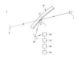
- FIG. 1 is a schematic diagram illustrating a HUD system according to a first embodiment.
- 2A and 2B are diagrams illustrating a laminated glass according to the first embodiment.
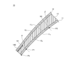
- FIG. 1 is a diagram (part 1) for explaining a local wedge angle.
- FIG. 2 is a diagram (part 2) for explaining the local wedge angle.
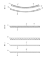
- 5A to 5C are diagrams (part 1) illustrating a method for producing laminated glass.
- 6A and 6B are diagrams (part 2) illustrating a method for producing laminated glass.
- FIG. 2 is a partial cross-sectional view illustrating a laminated glass according to a first modified example of the first embodiment.
- FIG. 4 is a cross-sectional view illustrating a laminated glass according to Modification 2 of the first embodiment.
- FIG. 11 is a plan view illustrating a laminated glass according to Modification 3 of the first embodiment.
- 10A and 10B are cross-sectional views illustrating a laminated glass according to Modification 4 of the first embodiment.
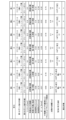
- FIG. 1 is a diagram illustrating an example and a comparative example.
- the vehicle is typically an automobile, but also refers to any moving object capable of mounting laminated glass, including trains, ships, aircraft, etc.
- planar view refers to viewing an object from the direction of a normal line passing through the center of gravity of the object's main surface, and the shape seen in this way is referred to as the planar shape.
- top and bottom used in the following explanation refer to the top and bottom when the laminated glass is installed in the vehicle.
- peripheral the outermost edge of a given member
- peripheral portion the area of the given member that has a width that is inscribed in the "periphery”
- FIG. 1 is a schematic diagram illustrating a HUD system according to a first embodiment.
- the HUD system 1 shown in Fig. 1 includes a laminated glass 10, a light source 50, a first optical system 60, an image display element 70, a second optical system 80, and a concave mirror 90.
- the HUD system 1 is a head-up display system for a vehicle that displays a virtual image on the vehicle exterior side of the laminated glass 10.
- the first optical system 60 and the second optical system 80 may be provided as necessary.
- the laminated glass 10 is, for example, a windshield for a vehicle, and P-polarized visible light is incident from the inside of the vehicle.
- the laminated glass 10 has a coating film 15 in the area where the P-polarized visible light reflected by the concave mirror 90 is incident.
- the coating film 15 may be formed on the entire surface of the laminated glass 10, or may be formed on only a part of the laminated glass 10. It is sufficient that the coating film 15 is formed at least in the area where the P-polarized light from the light source 50 is irradiated.
- the edges of the coating film 15 may be formed near the outer periphery of the laminated glass 10 or on or near the shielding layer to make the edges less noticeable.
- Light source 50 is a light source that emits P-polarized visible light, and is, for example, a light-emitting diode or a laser.
- Light source 50 may include optical components such as a polarizing plate or a lens that converts S-polarized light to P-polarized light.
- Light source 50 is, for example, composed of three light sources: a red light source, a green light source, and a blue light source.
- the first optical system 60 is composed of, for example, a prism or lens that combines light emitted from multiple light sources.
- the image display element 70 is an element that generates an intermediate image, and is, for example, a liquid crystal display element or an organic light-emitting element.
- the second optical system 80 is composed of, for example, a lens or a reflecting mirror.
- the concave mirror 90 is an optical component that reflects the intermediate image with a reflective surface having a predetermined curvature, and is positioned closest to the laminated glass 10 among the optical components positioned on the optical path between the light source 50 and the laminated glass 10.
- the HUD system 1 light emitted from the light source 50 passes through the first optical system 60 and reaches the image display element 70, where an intermediate image is formed.
- the intermediate image formed by the image display element 70 is enlarged by passing through the second optical system 80 and the concave mirror 90, and is irradiated onto the coating film 15 of the laminated glass 10.
- the intermediate image irradiated onto the coating film 15 is mainly reflected by the coating film 15 and guided to the viewpoint position I of the occupant, who recognizes the intermediate image as a virtual image V (HUD image) in front of the laminated glass 10.
- the occupant may be, for example, the driver of the vehicle.
- ⁇ is the angle of incidence when the P-polarized visible light emitted from the light source 50 is incident on the coating film 15 via the specified optical system.
- the angle of incidence ⁇ may be 57° (Brewster's angle), may be greater than 57°, or may be less than 57°.
- the HUD system 1 may have any configuration as long as it has at least the laminated glass 10 and the light source 50.
- the HUD system 1 may be a laser scanning system that scans laser light using an optical scanning unit formed of a MEMS (Micro Electro Mechanical Systems) or the like.
- MEMS Micro Electro Mechanical Systems
- FIG. 2A and 2B are diagrams illustrating a laminated glass according to the first embodiment.
- FIG. 2A is a schematic diagram illustrating the laminated glass as viewed from inside the vehicle toward the outside of the vehicle.
- FIG. 2B is a cross-sectional view taken along line A-A in FIG. 2A.
- the laminated glass 10 is a laminated glass for a vehicle that includes a first glass plate 11, a second glass plate 12, an intermediate film 13, shielding layers 14A and 14B, and a coating film 15.
- the laminated glass 10 can be used, for example, as a windshield of a vehicle.
- the first glass plate 11 and the second glass plate 12 are bonded together via an intermediate film 13.
- the first glass plate 11 is disposed on a first side that faces the inside of the vehicle when the laminated glass 10 is installed in the vehicle
- the second glass plate 12 is disposed on a second side that faces the outside of the vehicle when the laminated glass 10 is installed in the vehicle.
- the shielding layers 14A and 14B are provided as necessary.
- the laminated glass 10 has, for example, a complex curved shape that is curved in both the vertical and horizontal directions when installed in a vehicle.
- the complex curved shape is not limited to a shape that is curved in both the vertical and horizontal directions when installed in a vehicle, but includes a shape that is curved in any two or more different directions.
- the laminated glass 10 may have a single curved shape that is curved in only one of the vertical or horizontal directions when installed in a vehicle.
- the single curved shape is not limited to a shape that is curved in only the vertical or horizontal direction when installed in a vehicle, but includes a shape that is curved in only one of the directions.
- the laminated glass 10 is preferably curved so as to be convex toward the outside of the vehicle.
- the second glass sheet 12 is preferably curved so as to be convex toward the side opposite the interlayer film 13
- the first glass sheet 11 is preferably curved so as to be convex toward the interlayer film 13.
- the first glass sheet 11 is an interior glass sheet that becomes the interior side (first side) of the vehicle when the laminated glass 10 is installed in the vehicle.
- the first glass sheet 11 is curved.
- the first glass sheet 11 has a fourth surface 11 4 located on the opposite side to the intermediate film 13, and a third surface 11 3 facing the intermediate film 13.
- the reference symbol 11t indicates an upper edge that is located on the upper side when the laminated glass 10 is installed in the vehicle.
- the reference symbol 11b indicates a lower edge that is located on the lower side when the laminated glass 10 is installed in the vehicle.
- the first glass sheet 11 has an upper edge 11t, a lower edge 11b, and two side edges that connect the upper edge 11t and the lower edge 11b.
- the second glass sheet 12 is an exterior glass sheet that faces the vehicle exterior (second side) when the laminated glass 10 is installed in a vehicle.
- the second glass sheet 12 is curved.
- the second glass sheet 12 has a second surface 12 2 facing the intermediate film 13 and a first surface 12 1 located on the opposite side to the intermediate film 13.
- the second glass sheet 12 has an upper side, a lower side, and two side sides connecting the upper side and the lower side in a plan view.
- the minimum value of the radius of curvature is preferably 500 mm or more and 100,000 mm or less.
- the radii of curvature of the first glass plate 11 and the second glass plate 12 may be the same or different. When the radii of curvature of the first glass plate 11 and the second glass plate 12 are different, it is preferable that the radius of curvature of the first glass plate 11 is smaller than the radius of curvature of the second glass plate 12.
- the first glass plate 11 and the second glass plate 12 are a pair of glass plates facing each other, and the intermediate film 13 is located between the pair of glass plates.
- the first glass plate 11 and the second glass plate 12 are fixed together with the intermediate film 13 sandwiched between them.
- the intermediate film 13 is a film that bonds the first glass plate 11 and the second glass plate 12 together.
- the outer peripheral side of the interlayer 13 is preferably edge-treated.
- the outer peripheral side of the interlayer 13 is preferably treated so as not to protrude significantly from the outer peripheral sides of the first glass plate 11 and the second glass plate 12. It is preferable that the amount by which the outer peripheral side of the interlayer 13 protrudes from the outer peripheral sides of the first glass plate 11 and the second glass plate 12 is 150 ⁇ m or less in terms of not impairing the appearance. Details of the first glass plate 11, the second glass plate 12, and the interlayer 13 will be described later.
- the shielding layers 14A and 14B are opaque layers, and are provided, for example, in a strip shape along the periphery of the laminated glass 10.
- the shielding layers 14A and 14B are, for example, opaque colored ceramic layers, and may be of any color, but dark colors such as black, brown, gray, and dark blue are preferred, and black is more preferred.
- the shielding layers 14A and 14B may be a colored intermediate film or film with light-blocking properties, a combination of a colored intermediate film and a colored ceramic layer, or a layer with a dimming function.
- the colored film may be integrated with an infrared reflective film, etc.
- the width of the shielding layers 14A and 14B in a plan view is, for example, about 10 mm or more and 250 mm or less, preferably 20 mm or more and 220 mm or less, and more preferably 30 mm or more and 200 mm or less.
- the width of the shielding layers 14A and 14B may be the same or different.
- the presence of the opaque shielding layers 14A and 14B in the laminated glass 10 suppresses deterioration by ultraviolet rays of the adhesive made of a resin such as urethane that holds the peripheral portion of the laminated glass 10 to the vehicle body, and also improves the appearance by making the adhesive invisible from outside the vehicle.
- the shielding layers 14A and 14B can be formed, for example, by applying a ceramic color paste containing a fusible glass frit containing a black pigment onto a glass plate by screen printing or the like, and then firing the paste.
- the method of forming the shielding layers 14A and 14B is not limited to this.
- the shielding layers 14A and 14B can also be formed, for example, by applying an organic ink containing a black or dark color pigment onto a glass plate by screen printing or the like, and then drying the ink.
- the shielding layer 14A may be provided, for example, on the peripheral portion of the fourth surface 114 of the first glass plate 11.
- the shielding layer 14A may be provided on the peripheral portion of the fourth surface 114 of the first glass plate 11 via a coating film 15.
- the shielding layer 14A may be provided on the entire peripheral portion of the fourth surface 114 of the first glass plate 11, or may be provided on a part of the peripheral portion.
- the shielding layer 14A is provided only on the outer edge portion of the upper side 11t and two side sides of the fourth surface 114 of the first glass plate 11 in a plan view. That is, in the examples of FIGS. 2A and 2B, the shielding layer 14A is not provided on the outer edge portion close to the lower side 11b of the fourth surface 114 of the first glass plate 11 in a plan view.
- the shielding layer 14B may be provided, for example, on the peripheral portion of the second surface 122 of the second glass plate 12.
- the shielding layer 14B may be provided on a portion of the peripheral portion of the second surface 122 of the second glass plate 12.
- the shielding layer 14B may be provided on the entire peripheral portion of the second surface 122 of the second glass plate 12, or may be provided on a portion of the peripheral portion.
- the shielding layer 14B is provided on the entire peripheral portion of the second surface 122 of the second glass plate 12 in a plan view. Note that only one of the shielding layers 14A and 14B may be provided.
- the laminated glass 10 may have an information transmission/reception area 16.
- the information transmission/reception area 16 is provided within the opening of the shielding layer 14A and/or 14B of the laminated glass 10. That is, if the laminated glass 10 has only the shielding layer 14A, the information transmission/reception area 16 is provided within the opening of the shielding layer 14A. If the laminated glass 10 has only the shielding layer 14B, the information transmission/reception area 16 is provided within the opening of the shielding layer 14B. If the laminated glass 10 has both the shielding layers 14A and 14B, the information transmission/reception area 16 is provided at a position where the opening of the shielding layer 14A overlaps with the opening of the shielding layer 14B.
- the information transmission/reception area 16 is provided, for example, on the upper peripheral edge of the laminated glass 10.
- the information transmission/reception area 16 is an area where, for example, an information device that handles visible light, such as a visible light camera or an illuminance sensor, or an information device that handles infrared light, such as a LiDAR (Light Detection And Ranging) device, transmits and/or receives information.
- an information device that handles visible light, such as a visible light camera or an illuminance sensor, or an information device that handles infrared light, such as a LiDAR (Light Detection And Ranging) device, transmits and/or receives information.
- an information device can be placed on the inside of the information transmission/reception area 16.
- a HUD display area R for use in a head-up display is defined in a portion of the laminated glass 10.
- the HUD display area R is an area into which P-polarized light can enter from the first glass plate 11.
- the HUD display area R is not limited to one location, and may be, for example, divided and disposed in multiple locations in the vertical direction or multiple locations in the horizontal direction within the laminated glass 10 in a plan view.
- the HUD display region R reflects a projected image from inside the vehicle to display information.
- the HUD display region R is a range in an eye box based on SAE J1757-2 (2016) where light from the light source 50 is irradiated onto the laminated glass 10 when the HUD display position is moved.
- the HUD display region R is located, for example, in the vicinity of the lower side 11b of the fourth surface 114 of the first glass plate 11.
- a coating film 15 is disposed on the fourth surface 114 of the first glass plate 11.
- the coating film 15 only needs to be disposed so as to include the entire HUD display region R, and may be disposed on the entire laminated glass 10.
- the coating film 15 is disposed on the entire laminated glass 10. Disposing the coating film 15 on the entire laminated glass 10 is advantageous in that the boundary between the region where the coating film 15 is disposed and the surrounding region is not visible.
- the coating film 15 is a film that reflects the P-polarized visible light incident from the concave mirror 90 toward the inside of the vehicle, and is coated, for example, on the fourth surface 114 of the first glass plate 11.
- the coating film 15 is transparent to visible light.
- the film thickness of the coating film 15 is, for example, 50 nm or more and 500 nm or less.
- the coating film 15 is configured so that the visible light reflectance Rva is 10% or more when P-polarized visible light is incident at an incident angle of 65 deg.
- the coating film 15 examples include a film having a laminated structure of a high refractive index film/a low refractive index film, an infrared reflection film having a laminated structure of a metal film such as silver and a dielectric film, and a low-e film made of a transparent conductive film such as ITO.
- a film having a laminated structure of a high refractive index film/a low refractive index film is preferably used in terms of maintaining a high P-polarized light reflectance.
- the high refractive index film/low refractive index film has a two-layer structure, for example, the high refractive index film and the low refractive index film are laminated in this order on the fourth surface 114 of the first glass plate 11.
- the high refractive index film/low refractive index film has a three-layer structure or more, the high refractive index film and the low refractive index film are alternately laminated in any order on the fourth surface 114 of the first glass plate 11.
- the refractive index of the high refractive index film is 1.8 or more, 1.9 or more, 2.0 or more, or 2.1 or more, and preferably 2.5 or less, at a wavelength of 550 nm.
- the refractive index of the low refractive index film is typically less than 1.8, 1.7 or less, or 1.6 or less, and preferably 1.2 or more, at a wavelength of 550 nm.
- the high refractive index film preferably contains at least one of the following: oxides of Zr, Nb, or Sn; mixed oxides containing at least two of Ti, Zr, Nb, Si, Sb, Sn, Zn, and In; nitrides of Si and Zr; and mixed nitrides of Si or Zr.
- the low refractive index film preferably contains at least one of silicon oxide, silicon oxynitride, silicon oxycarbide, and mixed oxides. Examples of mixed oxides include a mixed oxide of silicon and aluminum, and a mixed oxide of silicon and zirconium.
- the first layer of the high refractive index film is optionally made of one or more sublayers.
- the thickness (geometric film thickness) of the first layer of the high refractive index film is preferably 50 nm or more and 100 nm or less, in particular 60 nm or more and 80 nm or less.
- the first layer of the low refractive index film is optionally made of one or more sublayers.
- the thickness (geometric film thickness) of the first layer of the low refractive index film is preferably 70 nm or more and 160 nm or less, in particular 100 nm or more and 140 nm or less.
- the light source or optical system is installed so that the angle of incidence of P-polarized light entering the coating film 15 is approximately 57 deg.
- the angle of incidence ⁇ may deviate from 57 deg.
- the incident angle ⁇ is 67 degrees or 72 degrees, more light passes through the coating film 15, and if no measures are taken, more light is reflected from the surface of the laminated glass 10 that is closer to the outside of the vehicle than the coating film 15.
- a virtual image may appear separated. This separated image is a double image, and the appearance of a double image reduces the visibility of the HUD image.
- the intermediate film 13 has a region with a wedge-shaped cross section whose thickness gradually increases from the lower side to the upper side of the fourth surface 114 of the first glass plate 11 when the laminated glass 10 is attached to the vehicle.
- an imaginary line passing through a first point Pt that bisects the upper side 11t of the fourth surface 114 of the first glass sheet 11 and a second point Pb that bisects the lower side 11b in a plan view is defined as a straight line S1.
- Point P1 shown in Fig. 3 indicates a position that is 100 mm away from the second point Pb by a distance L1 when measured on the straight line S1 along the fourth surface 114 of the first glass sheet 11.
- Point P2 shown in Fig. 3 indicates a position that is 500 mm away from the second point Pb by a distance L2 when measured on the straight line S1 along the fourth surface 114 of the first glass sheet 11.
- Fig. 4 is a partial cross-sectional view taken along a straight line S1 in Fig. 3.
- reference symbol N1 indicates a normal line to the fourth surface 114 of the first glass sheet 11 passing through point P1
- reference symbol N2 indicates a normal line to the fourth surface 114 of the first glass sheet 11 passing through point P2.
- the local wedge angle ⁇ at point P1 located 100 mm away from the second point Pb is greater than the local wedge angle ⁇ at point P2 located 500 mm away from the second point Pb.
- the local wedge angle at a certain point P is defined as a value obtained by dividing the change in thickness of the interlayer film 13 within a range of ⁇ 40 mm from the point P on the line S1 by the distance therebetween, that is, 80 mm. Moreover, the thickness of the interlayer film 13 at a certain point P is measured along a normal line to the fourth surface 114 of the first glass sheet 11 that passes through the point P.
- the local wedge angle ⁇ at the position of point P1 ((thickness of intermediate film 13 at 100 mm + 40 mm) - (thickness of intermediate film 13 at 100 mm - 40 mm)) / 80 mm.
- the local wedge angle ⁇ at the position of point P2 ((thickness of intermediate film 13 at 500 mm + 40 mm) - (thickness of intermediate film 13 at 500 mm - 40 mm)) / 80 mm.
- the prominence of the secondary image also varies depending on the projection distance of the HUD image.
- the projection distance of the HUD image is preferably 2 m or more, more preferably 3 m or more, even more preferably 5 m or more, and particularly preferably 10 m or more.
- the projection distance of the HUD image is the distance from the center of the eye box to the focal position of the virtual image V based on SAE J1757-2 (2016).
- the measurement method of the focal length of the HUD is based on SAE J1757-2 (2018).
- the projection distance of the HUD image increases, the secondary image becomes darker and the amount of separation of the secondary image from the primary image is reduced, making the secondary image less noticeable.
- the HUD image approaches the focal length of the driver while driving, improving the visibility of the HUD image.
- first glass plate 11, the second glass plate 12, and the intermediate film 13 will be described in detail.
- the first glass plate 11 and the second glass plate 12 may be inorganic glass or organic glass.
- the inorganic glass for example, soda lime glass, aluminosilicate glass, borosilicate glass, alkali-free glass, quartz glass, etc. may be used without any particular limitation.
- the second glass plate 12, which is the vehicle exterior side of the laminated glass 10, is preferably inorganic glass from the viewpoint of scratch resistance, and is preferably soda lime glass from the viewpoint of formability.
- the first glass plate 11 and the second glass plate 12 are soda lime glass, clear glass, green glass containing a predetermined amount or more of iron components, and dark green glass can be suitably used.
- glass that absorbs ultraviolet or infrared rays may be used, and further, transparent glass is preferable, but a glass plate colored to the extent that transparency is not impaired may be used.
- Inorganic glass may be either untempered glass or tempered glass.
- Untempered glass is made by forming molten glass into a flat plate and slowly cooling it.
- Tempered glass is made by forming a compressive stress layer on the surface of untempered glass.
- tempered glass can reduce residual stress by distributing stress isotropically.
- the tempered glass may be either physically tempered glass, such as air-cooled tempered glass, or chemically tempered glass.
- Physically tempered glass can be tempered by generating a compressive stress layer on the glass surface due to the temperature difference between the glass surface and the interior of the glass through an operation other than gradual cooling, such as rapidly cooling a glass sheet that has been uniformly heated during bending forming from a temperature near its softening point.
- Chemically strengthened glass can be strengthened by, for example, creating compressive stress on the glass surface using an ion exchange method after bending.
- Materials for organic glass include polycarbonate, acrylic resins such as polymethyl methacrylate, polyvinyl chloride, polystyrene, and other transparent resins.
- the first glass plate 11 and the second glass plate 12 are not limited to a trapezoidal or rectangular shape, and may be processed into various shapes and curvatures.
- the first glass plate 11 and the second glass plate 12 may be bent using gravity forming, press forming, roller forming, or the like.
- the thickness of the second glass sheet 12 is preferably 1.1 mm or more and 3 mm or less at its thinnest part. If the thickness of the second glass sheet 12 is 1.1 mm or more, the strength, such as resistance to flying stones, is sufficient. If the thickness of the second glass sheet 12 is 3 mm or less, the mass of the laminated glass 10 does not become too large, which is preferable in terms of fuel efficiency of the vehicle.
- the thickness of the second glass sheet 12 is more preferably 1.8 mm or more and 2.8 mm or less at its thinnest part, more preferably 1.8 mm or more and 2.6 mm or less, even more preferably 1.8 mm or more and 2.2 mm or less, and even more preferably 1.8 mm or more and 2.1 mm or less.
- the thickness of the first glass plate 11 is preferably 0.3 mm or more and 2.3 mm or less. If the thickness of the first glass plate 11 is 0.3 mm or more, it is easy to handle. If the thickness of the first glass plate 11 is 2.3 mm or less, the mass does not become too large.
- the thickness of the first glass sheet 11 is not appropriate, forming a laminated glass using two sheets of glass with particularly deep curvatures as the first glass sheet 11 and the second glass sheet 12 will result in a mismatch in the shapes of the two sheets, which will have a significant impact on the glass quality, such as residual stress after bonding.
- the thickness of the first glass sheet 11 0.3 mm or more and 2.3 mm or less glass quality such as residual stress can be maintained.
- Making the thickness of the first glass sheet 11 0.3 mm or more and 2.3 mm or less is particularly effective in maintaining glass quality in glass with a deep curvature. It is more preferable that the thickness of the first glass sheet 11 be 0.5 mm or more and 2.2 mm or less, and even more preferable that the thickness of the first glass sheet 11 be 0.7 mm or more and 2.1 mm or less. If the thickness of the first glass sheet 11 is within these ranges, the above-mentioned effects will be even more pronounced.
- a coating having water repellency, ultraviolet or infrared blocking properties, or a coating having low reflectance or low radiation properties may be provided on the outside of the first glass plate 11 and/or the second glass plate 12.
- a coating having ultraviolet or infrared blocking properties, low radiation properties, visible light absorption properties, coloring, etc. may be provided on the side of the first glass plate 11 and/or the second glass plate 12 that contacts the intermediate film 13.
- the first glass sheet 11 and the second glass sheet 12 are curved inorganic glass
- the first glass sheet 11 and the second glass sheet 12 are bent after being shaped by a float method or the like and before being bonded with the intermediate film 13.
- the bending is performed by softening the glass by heating.
- the heating temperature of the glass during bending is preferably controlled in the range of approximately 550°C to 700°C.
- thermoplastic resins are often used for the intermediate film 13, and examples of such thermoplastic resins include those conventionally used for this type of application, such as plasticized polyvinyl acetal resins, plasticized polyvinyl chloride resins, saturated polyester resins, plasticized saturated polyester resins, polyurethane resins, plasticized polyurethane resins, ethylene-vinyl acetate copolymer resins, ethylene-ethyl acrylate copolymer resins, cycloolefin polymer resins, ionomer resins, etc.
- a resin composition containing a modified hydrogenated block copolymer described in Japanese Patent No. 6065221 can also be suitably used.
- plasticized polyvinyl acetal resins are preferably used because they have an excellent balance of properties such as transparency, weather resistance, strength, adhesive strength, penetration resistance, impact energy absorption, moisture resistance, heat insulation, and sound insulation.
- thermoplastic resins may be used alone or in combination of two or more types.
- plasticized means that the resin has been plasticized by adding a plasticizer. The same applies to other plasticized resins.
- the object when a specific object is enclosed in the intermediate film 13, the object may be deteriorated by a specific plasticizer depending on the type of object. In such cases, it is preferable to use a resin that does not substantially contain the plasticizer.
- resins that do not contain plasticizers include ethylene-vinyl acetate copolymer (EVA) resins.
- the polyvinyl acetal resins include polyvinyl formal resins obtained by reacting polyvinyl alcohol (PVA) with formaldehyde, polyvinyl acetal resins in the narrow sense obtained by reacting PVA with acetaldehyde, and polyvinyl butyral (PVB) resins obtained by reacting PVA with n-butylaldehyde.
- PVB is particularly preferred because it has an excellent balance of properties such as transparency, weather resistance, strength, adhesive strength, penetration resistance, impact energy absorption, moisture resistance, heat insulation, and sound insulation.
- These polyvinyl acetal resins may be used alone or in combination of two or more types.
- the material forming the intermediate film 13 is not limited to thermoplastic resin.
- the intermediate film 13 may also contain functional particles such as infrared absorbing agents, ultraviolet absorbing agents, and luminescent agents.
- the intermediate film 13 may also have a colored portion called a shade band.
- the color pigment used to form the colored portion is one that can be used for plastics, and the amount added may be adjusted so that the visible light transmittance of the colored portion is 40% or less.
- organic color pigments such as azo-based, phthalocyanine-based, quinacridone-based, perylene-based, perinone-based, dioxazine-based, anthraquinone-based, or isoindolino-based, or inorganic color pigments such as oxides, hydroxides, sulfides, chromates, sulfates, carbonates, silicates, phosphates, arsenates, ferrocyanides, carbon, or metal powders may be used. These color pigments may be used alone or in combination of two or more types.
- the intermediate film 13 may have multiple layers.
- the intermediate film 13 may include three or more layers.
- the thickness of the interlayer film 13 is preferably 0.5 mm or more at its thinnest part. If the interlayer film 13 has multiple layers, the thickness of the interlayer film 13 is the total thickness of each layer. If the thickness of the interlayer film 13 at its thinnest part is 0.5 mm or more, the impact resistance required for laminated glass is sufficient. Furthermore, the thickness of the interlayer film 13 is preferably 3 mm or less at its thickest part. If the maximum thickness of the interlayer film 13 is 3 mm or less, the mass of the laminated glass will not become too large. It is more preferable that the maximum thickness of the interlayer film 13 is 2.8 mm or less, and even more preferable that it is 2.6 mm or less.
- each layer included in the intermediate film 13 is formed of the same material, but it may be formed of different materials.
- the above-mentioned materials be used for the portion that accounts for 50% or more of the thickness of the intermediate film 13.
- the above-mentioned resin material that will become the interlayer is appropriately selected and extruded in a heated and molten state using an extruder.
- the extrusion conditions such as the extrusion speed of the extruder, are set so as to be uniform.
- the extruded resin film is then stretched as necessary, for example, to give the upper and lower edges a curvature in accordance with the design of the laminated glass, and the interlayer film 13 is completed.
- the total thickness of the laminated glass 10 is preferably 2.8 mm or more and 10 mm or less. If the total thickness of the laminated glass 10 is 2.8 mm or more, sufficient rigidity can be ensured. Furthermore, if the total thickness of the laminated glass 10 is 10 mm or less, sufficient transmittance can be obtained and haze can be reduced.
- the total thickness of the laminated glass 10 is preferably 7 mm or less, more preferably 6 mm or less, and even more preferably 5 mm or less.
- the plate misalignment between the first glass plate 11 and the second glass plate 12 is preferably 1.5 mm or less, and more preferably 1 mm or less.
- the plate misalignment between the first glass plate 11 and the second glass plate 12 refers to the amount of misalignment between the outer peripheral side surface of the first glass plate 11 and the outer peripheral side surface of the second glass plate 12 in a plan view.
- misalignment between the first glass sheet 11 and the second glass sheet 12 on at least one side of the laminated glass 10 is 1.5 mm or less, this is preferable in terms of not impairing the appearance. If the misalignment between the first glass sheet 11 and the second glass sheet 12 on at least one side of the laminated glass 10 is 1.0 mm or less, this is even more preferable in terms of not impairing the appearance.
- a first glass sheet 11 having a third surface 113 and a fourth surface 114 , an interlayer film 13, and a second glass sheet 12 having a first surface 121 and a second surface 122 are prepared.
- the sheet thicknesses of the first glass sheet 11 and the second glass sheet 12 are constant.
- the film thickness of the interlayer film 13 is constant.
- an interlayer film 13 having a wedge-shaped cross section may be prepared.
- a coating film 15 having a visible light reflectance of 10% or more when P-polarized visible light is incident at an incident angle of 65 deg is formed on the fourth surface 114 of the first glass plate 11.
- the coating film 15 can be formed on the fourth surface 114 of the first glass plate 11 by, for example, a sputtering method or a CVD method.
- the coating film 15 is formed on the entire surface of the fourth surface 114 of the first glass plate 11, but the coating film 15 may be formed on a part of the fourth surface 114 of the first glass plate 11.
- the coating film 15 is formed on the fourth surface 114 of the first glass plate 11, but the coating film 15 may be formed on the third surface 113 of the first glass plate 11 or the second surface 122 of the second glass plate 12, as shown in Figs. 10A and 10B described later. Alternatively, the coating film 15 may be formed on a large piece of glass, and then the glass may be cut to prepare the first glass plate 11 having the coating film 15 formed thereon.
- the first glass sheet 11 and the second glass sheet 12 are bent as shown in FIG. 5C.
- the first glass sheet 11 and the second glass sheet 12 can be bent by, for example, a press molding method. Specifically, a mold with projections and recesses corresponding to the final shape of the laminated glass 10 is prepared, and the first glass sheet 11 and the second glass sheet 12 are heated to a predetermined temperature to soften them, and then pressed using this mold to bend the first glass sheet 11 and the second glass sheet 12.
- the first glass sheet A and the second glass sheet B may be bent by gravity molding, roller molding, or the like.
- one of the two opposing sides of the intermediate film 13 and its vicinity are stretched in the direction of the arrow along the one side in a plan view, but the stretching direction is not limited to this.
- the one side and its vicinity may be stretched in the left-right direction, and the degree of stretching may be different in the up-down direction.
- a stretching machine may be used for stretching.
- the intermediate film 13 becomes trapezoidal in plan view, as shown in FIG. 6B, and the stretched side and its vicinity become wedge-shaped in cross section.
- the intermediate film 13 When the intermediate film 13 is stretched strongly, the one side and its vicinity have an upper limit to the stretching, so the degree of stretching saturates, eliminating the thickness deviation, and the film is thinned with no or almost no wedge angle. In contrast, a wedge angle is generated in areas other than the vicinity of the one side, and the wedge angle in the vicinity of the one side is different from the wedge angle in the other areas. In other words, an intermediate film 13 with local wedge angles ⁇ and ⁇ as shown in FIG. 4 can be formed.
- the interlayer film 13 has a shape including a region with a wedge-shaped cross section whose thickness gradually increases from the lower side 11b to the upper side 11t of the fourth surface 114.
- a local wedge angle ⁇ at a position 100 mm from the second point Pb and a local wedge angle ⁇ at a position 500 mm from the second point Pb are extended so as to satisfy the formula ( ⁇ - ⁇ )>0.05 [mrad].
- the same procedure may be followed when preparing an interlayer film 13 with a wedge-shaped cross section that is not constant in thickness.
- the intermediate film 13 includes multiple layers, a laminate of the multiple layers is first produced and then the entire laminate is stretched.
- the stretched interlayer film 13 is placed between the third surface 113 of the first glass plate 11 and the second surface 122 of the second glass plate 12, and pressure-bonded.
- the interlayer film 13 is sandwiched between the first glass plate 11 and the second glass plate 12 so that the coating film 15 is on the outside to form a laminate.
- this laminate is placed in a rubber bag, a rubber chamber, a resin bag, or the like, and bonded at a temperature controlled in the range of about 70° C. to 110° C. in a vacuum with a gauge pressure controlled in the range of 100 kPa to ⁇ 65 kPa.
- the heating conditions, temperature conditions, and lamination method are appropriately selected.
- a laminated glass 10 with superior durability can be obtained.
- this heating and pressurizing process may not be used in order to simplify the process or in consideration of the characteristics of the material to be encapsulated in the laminated glass 10.
- the laminated glass 10 is completed through the above process.
- the so-called cold bending method may be used, in which the second glass sheet 12 is bent in advance, and the first glass sheet, which is in a flat state, is sandwiched between the interlayer film 13 and curved to match the shape of the second glass sheet 12 and bonded to produce the laminated glass 10.
- a film or device having functions such as heating, infrared reflection, light emission, power generation, light control, touch panel, visible light reflection, scattering, decoration or absorption may be present within a range that does not impair the effects of the present invention.
- the surface of the laminated glass 10 may have a film having functions such as anti-fogging, water repellency, heat shielding or low reflection.
- a film having functions such as heat shielding or heat generation may be present on the inner main surface of the first glass sheet 11 or the inner main surface of the second glass sheet 12.
- the first glass sheet 11 is provided with a coating film 15, but the second glass sheet 12 is not.
- the bending behavior of each glass sheet differs. Therefore, a mismatch may occur after bending.
- a mismatch is a state in which the peripheral portions of each glass sheet have different shapes.
- the mismatch can be a factor in the generation of bubbles in the interlayer film 13.
- a gap called an opening is generated between the lower side of the third surface 113 of the first glass sheet 11 and the interlayer film 13, which is likely to lead to bubbles in the interlayer film 13 after the vehicle is released onto the market.
- bubbles in the interlayer film 13 are generated significantly in particular near the lower side of a laminated glass having an interlayer film with a wedge-shaped cross section.
- the laminated glass 10 is designed so that the local wedge angle ⁇ and the local wedge angle ⁇ satisfy the formula ( ⁇ - ⁇ )>0.05 [mrad], thereby making it difficult for bubbles to form in the interlayer 13. That is, in the interlayer 13, the local wedge angle ⁇ near the lower edge 11b of the fourth surface 114 of the first glass sheet 11 is made small. Therefore, when the interlayer 13 is disposed between the first glass sheet 11 and the second glass sheet 12 and pressed, the first glass sheet 11 and the second glass sheet 12 are pressed in a nearly parallel manner near the lower edge 11b.
- the laminated glass 10 is preferably configured to satisfy the formula ⁇ 0.35 [mrad], and more preferably ⁇ 0.10 [mrad].
- the formula ( ⁇ +0.05 [mrad]) ⁇ 0.30 [mrad] is satisfied. If ⁇ is in this range, it is sufficient to reduce double images, and by not making ⁇ larger than necessary, it can also contribute to reducing the mismatch between the first glass sheet and the second glass sheet.
- the average thickness of the interlayer 13 in the range from 70 mm to 130 mm from the bottom edge 11b may be 0.80 mm or less, or 0.70 mm or less.
- the first glass sheet 11 may have a lower total iron content, calculated as Fe 2 O 3 by weight, than the second glass sheet 12.
- the second glass sheet 12 may have a total iron content, calculated as Fe 2 O 3 by weight, of 0.1% or more.
- the first glass sheet 11 may be clear glass, and the second glass sheet 12 may be green glass.
- the difference in thickness between the first glass sheet 11 and the second glass sheet 12 is preferably 0.3 mm or less, and more preferably less than 0.2 mm.
- FIG. 7 is a partial cross-sectional view illustrating a laminated glass according to Modification 1 of the first embodiment, and shows a cross section corresponding to FIG.
- the laminated glass 10A shown in FIG. 7 differs from the laminated glass 10 in that the interlayer 13 has been replaced with an interlayer 13A.
- the interlayer 13A has a three-layer structure. Specifically, the interlayer 13A has an interlayer 131 that is bonded to the first glass plate 11, an interlayer 132 that is bonded to the second glass plate 12, and an interlayer 133 that is sandwiched between the interlayer 131 and the interlayer 132.
- intermediate film 133 is a core layer and has a smaller shear storage modulus than intermediate films 131 and 132.
- Intermediate films 131 and 132 are skin layers and have a larger shear storage modulus than intermediate film 133.
- the shear storage modulus of intermediate film 131 and the shear storage modulus of intermediate film 132 may be the same or different.
- the shear storage modulus can be changed, for example, by adjusting the amount of plasticizer added to the resin.
- the shear storage modulus of the present invention is a value measured by a general dynamic viscoelasticity measurement method under measurement conditions of a temperature of 20°C, a frequency of 1 Hz, and a strain of 0.05%.
- the thickness of intermediate film 133 is preferably 0.05 mm or more and 0.3 mm or less, and more preferably 0.07 mm or more and 0.2 mm or less.
- the thickness of intermediate films 131 and 132 is preferably 0.1 mm or more and 2.0 mm or less, and more preferably 0.1 mm or more and 1.0 mm or less.
- the thickness of intermediate film 133 may be thinner than the thickness of intermediate films 131 and 132.
- the sound insulation of laminated glass 10A can be improved. Note that even if the interlayer has four or more layers and the shear storage modulus of any layer other than both outermost layers is made smaller than the shear storage modulus of both outermost layers, the sound insulation of laminated glass 10A can be improved in the same way as above.
- FIG. 8 is a cross-sectional view illustrating laminated glass according to Variation 2 of the first embodiment, showing a cross section corresponding to FIG. 2B.
- the laminated glass 10B shown in FIG. 8 differs from the laminated glass 10 in that a molding 17 is disposed on the outer edge of the fourth surface 11-4 of the first glass sheet 11.
- a shielding layer 14A is provided on the lower side of the fourth surface 11-4 of the first glass sheet 11 and its vicinity.
- the molding 17 is fixed to the vehicle interior side of the shielding layer 14A.
- the molding 17 can be fixed to the shielding layer 14A by, for example, adhering a resin member formed by extrusion molding to the shielding layer 14A of the first glass sheet 11. Since the molding 17 is disposed only on the outer edge of the fourth surface 11-4 of the first glass sheet 11, the end of the interlayer 13 is exposed from the molding 17 at the lower side 11b and its vicinity.
- FIG. 9 is a plan view illustrating a laminated glass according to the third modification of the first embodiment, and is a schematic diagram showing the laminated glass as viewed from inside the vehicle to outside the vehicle.
- L1 100 mm
- L2 500 mm.
- the laminated glass 10C shown in FIG. 9 differs from the laminated glass 10 in that the HUD display region R is located at a position overlapping the shielding layer 14B in a planar view. At least the region defining the local wedge angles ⁇ and ⁇ is located at a position overlapping the shielding layer 14B in a planar view.
- the shielding layer 14B is provided in a region including a range that is 60 mm or more and 540 mm or less from the second point Pb on the straight line S1.
- the shielding layer 14A may be provided in a region including a range that is 60 mm or more and 540 mm or less from the second point Pb on the straight line S1.
- the HUD display region R When the HUD display region R is located at a position that overlaps with the shielding layer 14B in a plan view, it is less susceptible to the effects of external light and the contrast of the HUD image is less likely to decrease, improving the visibility of the HUD image. As a result, when bubbles form in the intermediate film 13, the bubbles also become more visible, so as a countermeasure, it is effective to satisfy the formula ( ⁇ - ⁇ )>0.05 [mrad].
- FIGS. 10A and 10B are cross-sectional views illustrating laminated glass according to Variation 4 of the first embodiment, showing a cross section corresponding to that shown in FIG. 2B.
- the coating film 15 is provided on the fourth surface 114 of the first glass sheet 11.
- the laminated glass according to the present disclosure is not limited to the embodiment shown in Figures 2A and 2B, and the coating film 15 may be provided on the third surface 113 of the first glass sheet 11 as in the laminated glass 10D shown in Figure 10A.
- the coating film 15 may be provided on the second surface 122 of the second glass sheet 12 as in the laminated glass 10E shown in Figure 10B. In this way, in the laminated glass according to the present disclosure, it is sufficient that the coating film 15 is provided on the second surface 122 of the second glass sheet 12, the third surface 113 of the first glass sheet 11, or the fourth surface 114 of the first glass sheet 11.
- laminated glasses 10D and 10E As with laminated glass 10, mismatches may occur during the manufacturing process of laminated glasses 10D and 10E when bending and shaping the first glass sheet 11 and the second glass sheet 12, due to the different behavior of the respective glass sheets. Therefore, as with laminated glass 10, laminated glasses 10D and 10Eh can be designed so that the local wedge angles ⁇ and ⁇ satisfy the formula ( ⁇ - ⁇ )>0.05 [mrad], thereby making it difficult for bubbles to form in the interlayer 13.
- the main reflective surface becomes the surface of the coating film 15 that contacts the first glass plate 11, which is preferable in that the number of secondary images is limited to one, making the secondary images less noticeable.
- Examples and Comparative Examples Examples and comparative examples will be described below, but the present invention is not limited to these examples. Examples 1 and 4 are examples, and Examples 2, 3, 5, and 6 are comparative examples.
- Example 1 As the flat first glass sheet A that will be the inner sheet (glass sheet on the inside of the vehicle) when laminated, a clear glass manufactured by AGC (total iron content converted to Fe 2 O 3 : 0.08%) was prepared. As the flat second glass sheet B that will be the outer sheet (glass sheet on the outside of the vehicle), a green glass manufactured by AGC (total iron content converted to Fe 2 O 3 : 0.50%) was prepared. The dimensions of the first glass sheet A and the second glass sheet B were both 1,560 mm x 966 mm x sheet thickness 1.8 mm. Neither the first glass sheet A nor the second glass sheet B was wedge-shaped in cross section, and the sheet thickness was constant.
- the interlayer C a non-wedge sound insulation film with a constant thickness, in which three PVB films were laminated, was prepared.
- the thickness of the PVB films on both sides was 0.33 mm
- the thickness of the middle PVB film was 0.1 mm.
- a coating film (a TiZrO 2 /SiO 2 laminate film, geometric film thickness: 73.9 nm/99.5 nm) that reflects P-polarized visible light.
- first glass sheet A and the second glass sheet B were each heated to 600°C to soften them, and then pressed using this mold to bend the first glass sheet A and the second glass sheet B.
- a plastic film stretching machine D was used to stretch one of the opposing sides of the interlayer C and the area nearby to form a wedge shape in cross section.
- the stretching machine D used was the one shown in U.S. Pat. No. 2,933,759.
- the stretching machine D can stretch the interlayer C by heating it and aligning it with an umbrella-shaped cylinder.
- the degree of stretching can be selected depending on the opening degree (radius R) of the umbrella-shaped cylinder.
- R was set to 1,800 mm and the interlayer C was strongly stretched.
- the interlayer C was strongly stretched.
- there was no thickness deviation near that side because there was an upper limit to the stretch, and the film was thinned with no or almost no wedge angle.
- a wedge angle was formed in areas other than the area near that side, and a difference was created between the wedge angle near that side and the wedge angle in the other area.
- a laminate was prepared by sandwiching the stretched interlayer C between the curved first glass plate A provided with the coating film and the curved second glass plate B, and the first glass plate A and the second glass plate B interlayer C were bonded together in a vacuum controlled at a gauge pressure of 100 kPa to -65 kPa and a temperature controlled at a range of approximately 70°C to 110°C.
- a pressure bonding process was then carried out in which heat and pressure were applied under conditions controlled at a temperature of 100°C to 150°C and an absolute pressure of 0.6 MPa to 1.5 MPa, to produce a type A laminated glass.
- the type A laminated glass was designed to be used with an incident angle of P-polarized light of 62 degrees and a HUD projection distance of 6.2 m.
- Example 2 A laminated glass of Type A was produced in the same manner as in Example 1, except that the interlayer film C (non-wedge sound-insulating film) was not stretched at all.
- the first glass plate A was a clear glass manufactured by AGC with dimensions of 1580 mm x 811 mm x thickness of 1.8 mm
- the second glass plate B was a green glass manufactured by AGC with dimensions of 1580 mm x 811 mm x thickness of 2.0 mm
- a wedge sound-proof film with a certain wedge angle formed in advance was used as the interlayer film C.
- a laminated glass of type B was produced in the same manner as in Example 1.
- the laminated glass of type B was designed assuming that it would be used with an incident angle of P-polarized light of 67 degrees and a HUD projection distance of 2.5 m.
- an additional wedge angle was generated in addition to the wedge angle before stretching. More additional wedge angles were generated in areas other than the vicinity of one side than in the vicinity of one side.
- Example 5 A first glass plate A and a second glass plate B similar to those in Example 4 were prepared, an interlayer film C (non-wedge sound-insulating film) similar to that in Example 1 was prepared, and a type B laminated glass was produced in the same manner as in Example 1, except that the interlayer film C was not stretched at all.
- an interlayer film C non-wedge sound-insulating film
- Example 6 as a result of weakly stretching the interlayer film C, an additional wedge angle was generated in addition to the wedge angle before stretching. Approximately the same additional wedge angle was generated near one side and on the other side opposite the one side.
- Example 7 as a result of weakly stretching the interlayer film C, an additional wedge angle was generated in addition to the wedge angle before stretching. Approximately the same additional wedge angle was generated near one side and on the other side opposite the one side.
- the temperature was set to 140°C and left for 1 hour, and the presence or absence of bubbles was similarly confirmed. If no bubbles were observed even at 140°C, the glass was rated as "excellent (indicated by a ⁇ mark)", if bubbles were observed for the first time at 140°C, the glass was rated as "good (indicated by a ⁇ mark)", and if bubbles were observed even slightly at 130°C or less, the glass was rated as "poor (indicated by an ⁇ mark)".
- Evaluation 3 (measurement of the distance of the double image) was “good (indicated by a circle mark)” and Evaluation 4 (temperature at which foaming occurs) was “excellent (indicated by a ⁇ mark)"
- the evaluation was determined to be "excellent (indicated by a ⁇ mark)”.
- Table 1 summarizes types A and B, and Figure 11 summarizes examples 1 to 7.
- Example 1 Comparing Example 1 and Example 2 in FIG. 11, in Example 1, since the interlayer film C was strongly stretched, the difference ( ⁇ - ⁇ ) between the local wedge angle ⁇ in the HUD display area and the local wedge angle ⁇ on the lower side of the HUD display area was 0.07 [mrad]. Since the local wedge angle ⁇ in the HUD display area was a moderate value, the distance of the double image was short and the visibility of the HUD image was good. Therefore, the evaluation of the distance of the double image was good. In addition, since the local wedge angle ⁇ was small and the first glass sheet A and the second glass sheet B were pressed in a nearly parallel manner near the lower side of the laminated glass, no bubbles were generated in the interlayer film C even at 140°C. Therefore, the evaluation of bubbles was excellent. As a result, the overall evaluation was excellent.
- Example 2 because it was not stretched, the wedge angle of interlayer C was essentially zero, the distance of the double image was long, and the visibility of the HUD image was poor. As a result, the distance of the double image was rated as poor.
- the wedge angle was essentially zero and the first glass sheet A and the second glass sheet B were pressed in a nearly parallel manner at the bottom edge of the laminated glass and its vicinity, no bubbles were generated in interlayer C even at 140°C. For this reason, the bubble-forming rating was excellent. As a result, the overall rating was poor.
- Example 3 because interlayer film C was stretched weakly, the difference between the local wedge angle ⁇ in the HUD display area and the local wedge angle ⁇ on the lower side of the HUD display area ( ⁇ - ⁇ ) was 0.02 [mrad]. Because the local wedge angle ⁇ in the HUD display area was an appropriate value, the distance of the double image was short and the visibility of the HUD image was good. Therefore, the distance of the double image was rated as Good. However, because the stretching was insufficient and the local wedge angle ⁇ was not small enough, the first glass sheet A and the second glass sheet B were not pressed in a nearly parallel manner at the lower edge of the laminated glass and in the vicinity thereof, so bubbles occurred in interlayer film C at 130°C. For this reason, the bubble evaluation was poor. As a result, the overall evaluation was poor.
- Example 4 Comparing Example 4 and Example 5 in Figure 11, in Example 4, the interlayer film C, which had a certain wedge angle formed in advance, was strongly stretched, so the difference between the local wedge angle ⁇ in the HUD display area and the local wedge angle ⁇ at the lower edge of the HUD display area and its vicinity, ( ⁇ - ⁇ ), was 0.09 [mrad]. Because the local wedge angle ⁇ in the HUD display area was a moderate value, the distance of the double image was short and the visibility of the HUD image was good. Therefore, the evaluation of the distance of the double image was good.
- Example 5 because it was unstretched, the wedge angle of interlayer C was essentially zero, the distance of the double image was long, and the visibility of the HUD image was poor. As a result, the distance of the double image was rated as x. Meanwhile, the wedge angle was essentially zero, and the first glass sheet A and the second glass sheet B should have been pressed together in a nearly parallel manner near the bottom edge of the laminated glass, but bubbles occurred in interlayer C at 140°C. For this reason, the bubble-forming rating was good. As a result, the overall rating was poor.
- Example 6 because interlayer film C was stretched weakly, the difference between the local wedge angle ⁇ in the HUD display area and the local wedge angle ⁇ at the lower edge of the HUD display area and its vicinity, ( ⁇ - ⁇ ), was 0.02 [mrad]. Because the local wedge angle ⁇ in the HUD display area was an appropriate value, the distance of the double image was short and the visibility of the HUD image was good. Therefore, the distance of the double image was rated as Good. However, because the stretching was insufficient and the local wedge angle ⁇ was not small enough, the first glass sheet A and the second glass sheet B were not pressed in a nearly parallel manner at the lower edge of the laminated glass and its vicinity, so bubbles occurred in interlayer film C at 120°C. For this reason, the bubble evaluation was poor. As a result, the overall evaluation was poor.
- Example 4 received a good evaluation of foaming
- Example 6 received a poor evaluation of foaming. This is thought to be because Example 4 has a larger ( ⁇ - ⁇ ) value than Example 6, which causes the first glass sheet and the second outer glass sheet to approach each other closer at the bottom edge of the laminated glass and in its vicinity, thereby suppressing the generation of foaming.
- ⁇ - ⁇ ⁇ - ⁇
- a laminated glass comprising: a curved first glass plate; a curved second glass plate; and an interlayer film positioned between the first glass plate and the second glass plate and bonding the first glass plate and the second glass plate, a surface of the first glass sheet located on an opposite side to the intermediate film is defined as a fourth surface, a surface of the first glass sheet located on the intermediate film side is defined as a third surface, a surface of the second glass sheet located on the intermediate film side is defined as a second surface, and a surface of the second glass sheet located on the opposite side to the intermediate film is defined as a first surface, a coating film is provided on the second surface, the third surface, or the fourth surface, the coating film has a visible light reflectance of 10% or more when P-polarized visible light is incident at an incident angle of 65 deg; the interlayer film has a region having a wedge-shaped cross section whose thickness gradually increases from a lower side toward an upper side when
- (Appendix 5) The laminated glass according to claim 4, wherein in the interlayer film, a shear storage modulus of any layer other than both outermost layers is smaller than a shear storage modulus of both outermost layers.
- Appendix 6) Appendices 6. The laminated glass according to any one of Appendices 1 to 5, wherein the average thickness of the interlayer film in an area on the straight line that is 60 mm or more and 140 mm or less from the second point is 0.80 mm or less.
- (Appendix 7) A molding is disposed on an outer edge of the fourth surface; 7. The laminated glass according to claim 1, wherein an end of the interlayer film is exposed from the molding on the lower side.
- the first glass sheet has a lower sum of all iron contents, calculated as Fe2O3 by weight, than the second glass sheet;
- a shielding layer is provided on an outer edge portion of the lower side of the second surface in a plan view, Appendices 9.
- Appendix 11 11.
- Appendix 12 12.
- a method for manufacturing laminated glass comprising: a curved first glass plate; a curved second glass plate; and an interlayer film positioned between the first glass plate and the second glass plate and bonding the first glass plate to the second glass plate, the method comprising the steps of: providing the first glass plate having a third surface and a fourth surface, the interlayer film, and the second glass plate having a first surface and a second surface; forming a coating film on the second surface, the third surface, or the fourth surface, the coating film having a visible light reflectance of 10% or more when P-polarized visible light is incident at an incident angle of 65 deg; a step of bending the first glass sheet and the second glass sheet after the step of forming the coating film; extending at least one of two opposing sides of the intermediate film and a portion adjacent thereto along the one side in a plan view; and disposing the extended interlayer film between the third surface of the first glass sheet and the second surface of the second glass sheet and pressing the interlayer film together.
- the interlayer film has a region having a wedge-shaped cross section whose thickness gradually increases from the lower side to the upper side of the fourth surface when the laminated glass is installed in a vehicle, a local wedge angle ⁇ at a position 100 mm from the second point and a local wedge angle ⁇ at a position 500 mm from the second point on a line passing through a first point dividing the upper side in half and a second point dividing the lower side in half in a plan view are extended so that the formula: ( ⁇ - ⁇ )>0.05 [mrad] is satisfied.
Landscapes
- Engineering & Computer Science (AREA)
- Physics & Mathematics (AREA)
- Chemical & Material Sciences (AREA)
- Mechanical Engineering (AREA)
- General Physics & Mathematics (AREA)
- Optics & Photonics (AREA)
- General Chemical & Material Sciences (AREA)
- Life Sciences & Earth Sciences (AREA)
- Chemical Kinetics & Catalysis (AREA)
- Geochemistry & Mineralogy (AREA)
- Materials Engineering (AREA)
- Organic Chemistry (AREA)
- Ceramic Engineering (AREA)
- Joining Of Glass To Other Materials (AREA)
Priority Applications (5)
| Application Number | Priority Date | Filing Date | Title |
|---|---|---|---|
| JP2025511031A JPWO2024204369A1 (https=) | 2023-03-29 | 2024-03-27 | |
| CN202480022636.8A CN120897896A (zh) | 2023-03-29 | 2024-03-27 | 夹层玻璃及其制造方法 |
| EP24780471.9A EP4692015A1 (en) | 2023-03-29 | 2024-03-27 | Laminated glass and method for manufacturing same |
| KR1020257027614A KR20250165587A (ko) | 2023-03-29 | 2024-03-27 | 합판 유리 및 그 제조 방법 |
| US19/338,198 US20260014779A1 (en) | 2023-03-29 | 2025-09-24 | Laminated glass and method for producing same |
Applications Claiming Priority (2)
| Application Number | Priority Date | Filing Date | Title |
|---|---|---|---|
| JP2023052990 | 2023-03-29 | ||
| JP2023-052990 | 2023-03-29 |
Related Child Applications (1)
| Application Number | Title | Priority Date | Filing Date |
|---|---|---|---|
| US19/338,198 Continuation US20260014779A1 (en) | 2023-03-29 | 2025-09-24 | Laminated glass and method for producing same |
Publications (1)
| Publication Number | Publication Date |
|---|---|
| WO2024204369A1 true WO2024204369A1 (ja) | 2024-10-03 |
Family
ID=92905476
Family Applications (1)
| Application Number | Title | Priority Date | Filing Date |
|---|---|---|---|
| PCT/JP2024/012280 Ceased WO2024204369A1 (ja) | 2023-03-29 | 2024-03-27 | 合わせガラス及びその製造方法 |
Country Status (6)
| Country | Link |
|---|---|
| US (1) | US20260014779A1 (https=) |
| EP (1) | EP4692015A1 (https=) |
| JP (1) | JPWO2024204369A1 (https=) |
| KR (1) | KR20250165587A (https=) |
| CN (1) | CN120897896A (https=) |
| WO (1) | WO2024204369A1 (https=) |
Citations (10)
| Publication number | Priority date | Publication date | Assignee | Title |
|---|---|---|---|---|
| US2933759A (en) | 1956-10-16 | 1960-04-26 | Pittsburgh Plate Glass Co | Apparatus for stretching plastic |
| JP2013163627A (ja) * | 2012-02-13 | 2013-08-22 | Asahi Glass Co Ltd | 樹脂モールディング付き透明積層体、車両または建物の窓部材、および樹脂モールディング付き透明積層体の製造方法 |
| JP2014024752A (ja) * | 2007-12-07 | 2014-02-06 | Saint-Gobain Glass France | 合わせガラスからなる曲面の車両用フロントガラス |
| JP2016107632A (ja) * | 2014-11-10 | 2016-06-20 | 株式会社クラレ | 積層体及び合わせガラス |
| JP6065221B2 (ja) | 2013-06-13 | 2017-01-25 | 日本ゼオン株式会社 | 合わせガラス板 |
| WO2017155066A1 (ja) * | 2016-03-11 | 2017-09-14 | 日本板硝子株式会社 | ウインドシールド |
| JP2020528865A (ja) * | 2017-07-28 | 2020-10-01 | ピルキントン グループ リミテッド | 窓アセンブリ |
| WO2022022886A1 (de) * | 2020-07-29 | 2022-02-03 | Saint-Gobain Glass France | Projektionsanordnung für ein head-up-display (hud) mit p-polarisierter strahlung |
| WO2022207004A1 (zh) | 2021-04-16 | 2022-10-06 | 福耀玻璃工业集团股份有限公司 | 抬头显示玻璃和抬头显示系统 |
| JP2023052990A (ja) | 2017-08-25 | 2023-04-12 | 株式会社三洋物産 | 遊技機 |
-
2024
- 2024-03-27 WO PCT/JP2024/012280 patent/WO2024204369A1/ja not_active Ceased
- 2024-03-27 JP JP2025511031A patent/JPWO2024204369A1/ja active Pending
- 2024-03-27 EP EP24780471.9A patent/EP4692015A1/en active Pending
- 2024-03-27 KR KR1020257027614A patent/KR20250165587A/ko active Pending
- 2024-03-27 CN CN202480022636.8A patent/CN120897896A/zh active Pending
-
2025
- 2025-09-24 US US19/338,198 patent/US20260014779A1/en active Pending
Patent Citations (10)
| Publication number | Priority date | Publication date | Assignee | Title |
|---|---|---|---|---|
| US2933759A (en) | 1956-10-16 | 1960-04-26 | Pittsburgh Plate Glass Co | Apparatus for stretching plastic |
| JP2014024752A (ja) * | 2007-12-07 | 2014-02-06 | Saint-Gobain Glass France | 合わせガラスからなる曲面の車両用フロントガラス |
| JP2013163627A (ja) * | 2012-02-13 | 2013-08-22 | Asahi Glass Co Ltd | 樹脂モールディング付き透明積層体、車両または建物の窓部材、および樹脂モールディング付き透明積層体の製造方法 |
| JP6065221B2 (ja) | 2013-06-13 | 2017-01-25 | 日本ゼオン株式会社 | 合わせガラス板 |
| JP2016107632A (ja) * | 2014-11-10 | 2016-06-20 | 株式会社クラレ | 積層体及び合わせガラス |
| WO2017155066A1 (ja) * | 2016-03-11 | 2017-09-14 | 日本板硝子株式会社 | ウインドシールド |
| JP2020528865A (ja) * | 2017-07-28 | 2020-10-01 | ピルキントン グループ リミテッド | 窓アセンブリ |
| JP2023052990A (ja) | 2017-08-25 | 2023-04-12 | 株式会社三洋物産 | 遊技機 |
| WO2022022886A1 (de) * | 2020-07-29 | 2022-02-03 | Saint-Gobain Glass France | Projektionsanordnung für ein head-up-display (hud) mit p-polarisierter strahlung |
| WO2022207004A1 (zh) | 2021-04-16 | 2022-10-06 | 福耀玻璃工业集团股份有限公司 | 抬头显示玻璃和抬头显示系统 |
Non-Patent Citations (1)
| Title |
|---|
| See also references of EP4692015A1 |
Also Published As
| Publication number | Publication date |
|---|---|
| JPWO2024204369A1 (https=) | 2024-10-03 |
| EP4692015A1 (en) | 2026-02-11 |
| US20260014779A1 (en) | 2026-01-15 |
| CN120897896A (zh) | 2025-11-04 |
| KR20250165587A (ko) | 2025-11-26 |
Similar Documents
| Publication | Publication Date | Title |
|---|---|---|
| JP7601011B2 (ja) | ヘッドアップディスプレイシステム | |
| JP7460005B2 (ja) | 合わせガラス | |
| US12585113B2 (en) | Laminated glass and head-up display system | |
| US10353200B2 (en) | Laminated glass | |
| CN108973608B (zh) | 夹层玻璃 | |
| US12162329B2 (en) | Vehicle | |
| US20250018688A1 (en) | Laminated glass | |
| CN111356949A (zh) | 用于车辆的投影装置,包含侧玻璃 | |
| EP3381880B1 (en) | Laminated glass | |
| WO2021002253A1 (ja) | ガラス | |
| WO2024204369A1 (ja) | 合わせガラス及びその製造方法 | |
| JP2023061360A (ja) | 合わせガラス及びその製造方法 | |
| US20260042281A1 (en) | Laminated glass | |
| JP2025126895A (ja) | 合わせガラス | |
| WO2026018834A1 (ja) | 合わせガラス、ヘッドアップディスプレイシステム | |
| JP2025097638A (ja) | 車両用表示システム | |
| WO2025018285A1 (ja) | 合わせガラス | |
| CN120503473A (zh) | 夹层玻璃 | |
| US20250312993A1 (en) | Laminated glass | |
| WO2024232279A1 (ja) | 合わせガラス及びガラス板 | |
| WO2023127677A1 (ja) | 合わせガラスおよび合わせガラスの製造方法 |
Legal Events
| Date | Code | Title | Description |
|---|---|---|---|
| 121 | Ep: the epo has been informed by wipo that ep was designated in this application |
Ref document number: 24780471 Country of ref document: EP Kind code of ref document: A1 |
|
| ENP | Entry into the national phase |
Ref document number: 1020257027614 Country of ref document: KR Free format text: ST27 STATUS EVENT CODE: A-0-1-A10-A15-NAP-PA0105 (AS PROVIDED BY THE NATIONAL OFFICE) |
|
| ENP | Entry into the national phase |
Ref document number: 2025511031 Country of ref document: JP Kind code of ref document: A |
|
| WWE | Wipo information: entry into national phase |
Ref document number: 2025511031 Country of ref document: JP |
|
| WWE | Wipo information: entry into national phase |
Ref document number: CN2024800226368 Country of ref document: CN Ref document number: 202480022636.8 Country of ref document: CN |
|
| WWE | Wipo information: entry into national phase |
Ref document number: 2024780471 Country of ref document: EP |
|
| NENP | Non-entry into the national phase |
Ref country code: DE |
|
| WWP | Wipo information: published in national office |
Ref document number: 202480022636.8 Country of ref document: CN |
|
| ENP | Entry into the national phase |
Ref document number: 2024780471 Country of ref document: EP Effective date: 20251029 |
|
| ENP | Entry into the national phase |
Ref document number: 2024780471 Country of ref document: EP Effective date: 20251029 |
|
| ENP | Entry into the national phase |
Ref document number: 2024780471 Country of ref document: EP Effective date: 20251029 |
|
| ENP | Entry into the national phase |
Ref document number: 2024780471 Country of ref document: EP Effective date: 20251029 |
|
| ENP | Entry into the national phase |
Ref document number: 2024780471 Country of ref document: EP Effective date: 20251029 |
|
| ENP | Entry into the national phase |
Ref document number: 2024780471 Country of ref document: EP Effective date: 20251029 |
|
| ENP | Entry into the national phase |
Ref document number: 2024780471 Country of ref document: EP Effective date: 20251029 |
|
| ENP | Entry into the national phase |
Ref document number: 2024780471 Country of ref document: EP Effective date: 20251029 |
|
| WWP | Wipo information: published in national office |
Ref document number: 2024780471 Country of ref document: EP |