WO2024204312A1 - 熱デバイス - Google Patents
熱デバイス Download PDFInfo
- Publication number
- WO2024204312A1 WO2024204312A1 PCT/JP2024/012188 JP2024012188W WO2024204312A1 WO 2024204312 A1 WO2024204312 A1 WO 2024204312A1 JP 2024012188 W JP2024012188 W JP 2024012188W WO 2024204312 A1 WO2024204312 A1 WO 2024204312A1
- Authority
- WO
- WIPO (PCT)
- Prior art keywords
- metal member
- metal
- opening
- thermal device
- welded portion
- Prior art date
- Legal status (The legal status is an assumption and is not a legal conclusion. Google has not performed a legal analysis and makes no representation as to the accuracy of the status listed.)
- Ceased
Links
Images






Classifications
-
- F—MECHANICAL ENGINEERING; LIGHTING; HEATING; WEAPONS; BLASTING
- F28—HEAT EXCHANGE IN GENERAL
- F28D—HEAT-EXCHANGE APPARATUS, NOT PROVIDED FOR IN ANOTHER SUBCLASS, IN WHICH THE HEAT-EXCHANGE MEDIA DO NOT COME INTO DIRECT CONTACT
- F28D15/00—Heat-exchange apparatus with the intermediate heat-transfer medium in closed tubes passing into or through the conduit walls ; Heat-exchange apparatus employing intermediate heat-transfer medium or bodies
- F28D15/02—Heat-exchange apparatus with the intermediate heat-transfer medium in closed tubes passing into or through the conduit walls ; Heat-exchange apparatus employing intermediate heat-transfer medium or bodies in which the medium condenses and evaporates, e.g. heat pipes
Definitions
- This disclosure relates to thermal devices.
- thermal devices that utilize the latent heat of fluids are known.
- a vapor chamber which is one type of thermal device, releases heat from a heat-generating component by transporting heat from a high-temperature area to a low-temperature area using the latent heat associated with the evaporation and condensation of a working fluid sealed inside (see Patent Document 1).
- a thermal device has a ceramic container having an internal space and a communication passage that connects the internal space to the outside, a fluid located in the internal space, and a sealing portion that closes a first opening that is an opening of the communication passage.
- the sealing portion is located on the container and has a first metal member that has a second opening that connects to the first opening, a second metal member that closes the second opening of the first metal member, and a welded portion where the first metal member and the second metal member are welded.
- FIG. 1 is a perspective view of a heat dissipation device according to an embodiment.
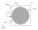
- FIG. 2 is a view of the first member according to the embodiment as viewed in the positive direction of the Z axis from the negative direction of the Z axis.
- FIG. 3 is a view of the second member according to the embodiment as viewed in the negative direction of the Z axis from the positive direction of the Z axis.
- FIG. 4 is a view of the intermediate member according to the embodiment, viewed from the Z-axis positive direction side to the Z-axis negative direction side.
- 5 is a diagram in which the first groove formation region shown in FIG. 2 and the second groove formation region shown in FIG. 3 are superimposed on the intermediate member shown in FIG. FIG.
- FIG. 6 is a diagram in which the third frame region is omitted from the diagram shown in FIG.
- FIG. 7 is a diagram for explaining the flow of the working fluid in the heat dissipation device according to the embodiment.
- FIG. 8 is a schematic cross-sectional view showing an example of the configuration of the communication passage.
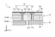
- FIG. 9 is a schematic cross-sectional view showing the configuration of the sealing portion.
- FIG. 10 is a schematic plan view showing the configuration of the sealing portion.
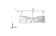
- FIG. 11 is a cross-sectional view that typically shows metal crystals that form the first metal member, the second metal member, and the welded portion.
- FIG. 12 is a diagram showing an SEM image of the vicinity of the boundary between the first metal member and the welded portion in the sealing portion according to the example.
- FIG. 13 is a diagram showing an SEM image of a cross section of a sealing portion according to an example.
- drawings referenced below may show an orthogonal coordinate system that defines the X-axis, Y-axis, and Z-axis directions that are mutually perpendicular, with the positive Z-axis direction being the vertically upward direction.
- a heat dissipation device that efficiently transfers heat from a high temperature area to a low temperature area by utilizing the latent heat associated with the evaporation and condensation of a fluid, specifically a vapor chamber, will be described.
- the thermal device may be referred to as a heat dissipation device.
- FIG. 1 is a perspective view of the heat dissipation device according to the embodiment.
- the heat dissipation device 1 has a container 2.
- the container 2 is made of ceramic.
- the container 2 may have a first member 10, a second member 20, and an intermediate member 30.
- the first member 10, the second member 20, and the intermediate member 30 are all plate-shaped, and the first member 10 and the second member 20 sandwich the intermediate member 30.
- the container 2 may have an operating region 100 and a frame region 200.
- the operating region 100 may have an internal space, and the internal space may be filled with a fluid, specifically, a working liquid as a phase-changing substance.
- a working liquid as a phase-changing substance.
- the working liquid include water, a hydrocarbon compound, an organic liquid such as ethanol or methanol, and ammonia.
- the frame region 200 is a region that surrounds the operating region 100.
- the frame region 200 is a region of the heat dissipation device 1 that is outside the operating region 100. While the operating region 100 is generally hollow, the frame region 200 may be generally solid.
- the frame region 200 is an area that is intentionally made wide in order to, for example, prevent the working fluid or vapor of the working fluid from leaking from the interface between the first member 10 and the intermediate member 30 or the interface between the second member 20 and the intermediate member 30, or to prevent the outside atmosphere from entering the internal space of the working region 100 from the above-mentioned interfaces, i.e., to ensure the airtightness of the working region 100.
- the container 2 may have two communication passages 60 that connect the internal space of the operating area 100 with the outside. Note that, although an example in which the container 2 has two communication passages 60 is shown here, it is sufficient for the container 2 to have at least one communication passage 60.
- one of the two communication passages 60 may be used as a flow path for injecting working fluid, and the other may be used as a flow path for discharging gas.
- working fluid is injected into the internal space of the operating region 100 from one of the communication passages 60, and gas present in the internal space of the operating region 100 is discharged to the outside from the other communication passage 60.
- one communication passage 60 is located near one of the four corners of the first member 10, and the other communication passage 60 is located near the corner diagonally opposite the one communication passage 60.
- Each communication passage 60 is closed by a sealing portion 70. This seals the internal space of the heat dissipation device 1, and the working fluid is sealed in the working region 100. In this way, the heat dissipation device 1 is a sealed container with a sealed interior.
- the working fluid may be filled at a ratio of, for example, 10% by volume or more and 95% by volume or less with respect to the total volume of the internal space of the operating region 100.
- the ratio may be 30% by volume or more and 75% by volume or less. More preferably, the ratio may be 40% by volume or more and 65% by volume or less.
- the remaining part of the internal space of the operating region 100 other than the working fluid may be in a vacuum state containing some vaporized working fluid. This makes it possible to maintain gas-liquid equilibrium even in high-temperature environments, making it less likely to dry out, and also allows for efficient thermal diffusion even in low-temperature environments, making it possible to increase thermal diffusivity in a variety of temperature ranges.
- the first member 10, the second member 20, and the intermediate member 30 are made of ceramic.
- the ceramic that can be used to form the first member 10, the second member 20, and the intermediate member 30 include alumina (Al 2 O 3 ), zirconia (ZrO 2 ), silicon carbide (SiC), silicon nitride (Si 3 N 4 ), aluminum nitride (AlN), cordierite (Mg 2 Al 3 (AlSi 5 O 18 )), and silicon-impregnated silicon carbide (SiSiC).
- the ceramic that forms the first member 10, the second member 20, and the intermediate member 30 may be polycrystalline or single crystalline.
- alumina as the ceramic that constitutes the first member 10, the second member 20, and the intermediate member 30, since it is inexpensive, has little environmental impact, and is easy to process.
- Metal heat dissipation devices are difficult to achieve rigidity due to the material and manufacturing method, and are difficult to make thin.
- metal heat dissipation devices have room for improvement in terms of corrosion resistance, since the parts that come into contact with the working fluid are made of metal.
- the heat dissipation device 1 according to the embodiment has first member 10, second member 20, and intermediate member 30 all made of ceramic, making it easier to make it thin compared to metal heat dissipation devices and also providing excellent corrosion resistance.
- the heat dissipation device 1 is installed with the first member 10 facing upward, but the orientation of the heat dissipation device 1 is not limited to the example in FIG. 1.
- the heat dissipation device 1 may be installed with the first member 10 facing downward.
- the heat dissipation device 1 may be placed vertically, not limited to horizontally as shown in FIG. 1.
- the sealing portion 70 according to the embodiment has a first metal member 71, a second metal member 72, and a welded portion 73.
- the sealing portion 70 according to the embodiment has a configuration in which the first metal member 71 and the second metal member 72 are integrated by welding. With this configuration, the heat dissipation device 1 according to the embodiment can improve the sealing reliability of the fluid.
- FIG. 2 is a view of the first member 10 according to the embodiment, viewed from the negative Z-axis direction side toward the positive Z-axis direction.
- FIG. 2 shows the bottom surface of the first member 10, i.e., the third surface that faces the first surface, which is the top surface of the intermediate member 30.
- the first member 10 has a lattice-shaped first groove portion 11 on the third surface.
- the first groove portion 11 may have a first recess 11a recessed into the third surface, and a plurality of first protrusions 11b located within the first recess 11a.
- the first recess 11a is located in the center of the third surface.
- the outline of the first recess 11a in plan view may be, for example, circular. However, this is not limited thereto, and the outline of the first recess 11a in plan view may be, for example, rectangular.
- the multiple first protrusions 11b are arranged in the vertical and horizontal directions at intervals within the first recess 11a.
- the first recess 11a and the multiple first protrusions 11b give the first groove portion 11 a lattice shape.
- the first groove forming area 110 constitutes part of the operating area 100.
- the first member 10 also has a rectangular frame-shaped first frame area 210 that surrounds the first groove forming area 110.
- the first frame area 210 constitutes part of the frame area 200.
- the first frame region 210 may have two through holes 61 that penetrate the first member 10 in the thickness direction, here in the Z-axis direction.
- the through holes 61 form part of the communication passage 60.
- a heat source is disposed in the center of the upper surface of the first member 10, i.e., the fifth surface located opposite the lower surface of the first member 10.
- FIG. 3 is a view of the second member 20 according to the embodiment, viewed from the positive Z-axis direction side in the negative Z-axis direction.
- FIG. 3 shows the fourth surface of the second member 20, which faces the second surface, i.e., the lower surface of the intermediate member 30.
- the second member 20 has a lattice-shaped second groove portion 21 on the fourth surface.
- the second groove portion 21 may have a second recess 21a recessed into the fourth surface, and a plurality of second protrusions 21b located within the second recess 21a.
- the second recess 21a is located in the center of the fourth surface.
- the outline of the second recess 21a in plan view may be, for example, circular. However, this is not limited thereto, and the outline of the second recess 21a in plan view may be, for example, rectangular.
- the second protrusions 21b are arranged in the second recess 21a at intervals in the vertical and horizontal directions.
- the second recess 21a and the second protrusions 21b give the second groove 21 a lattice shape.
- the second groove forming area 120 constitutes part of the operating area 100.
- the second member 20 also has a rectangular frame-shaped second frame area 220 that surrounds the second groove forming area 120.
- the second frame area 220 constitutes part of the frame area 200.
- the size of the second groove forming region 120 in the second member 20 is the same as the size of the first groove forming region 110 in the first member 10.
- the position of the second groove forming region 120 on the fourth surface of the second member 20 is the same as the position of the first groove forming region 110 on the third surface of the first member 10.
- the working fluid can be circulated efficiently in the internal space of the heat dissipation device 1.
- the first groove portion 11 and the second groove portion 21 do not necessarily have to be lattice-shaped.
- the second frame region 220 may have two recesses 62 recessed into the fourth surface, which is the upper surface of the second member 20.
- the second frame region 220 may also have two grooves 63. One end of the grooves 63 opens into the recesses 62, and the other end opens into the second groove forming region 120.
- the recesses 62 and the grooves 63 form part of the communication passage 60.
- FIG. 4 is a view of the intermediate member 30 according to the embodiment, viewed from the positive Z-axis direction side to the negative Z-axis direction.
- the intermediate member 30 may have a third frame region 230 having a rectangular frame shape.
- the third frame region 230 constitutes a part of the frame region 200.
- the intermediate member 30 may have a central portion 32 that is circular in plan view and located inside the third frame region 230, and a plurality of connecting portions 33 that are located between the central portion 32 and the third frame region 230 and connect the central portion 32 and the third frame region 230.
- the central portion 32 may be located in the center of the intermediate member 30.
- the multiple connecting portions 33 may extend radially from the central portion 32 toward the third frame region 230 at intervals.
- the intermediate member 30 may further have a plurality of steam holes 36 and a plurality of return holes 37.
- the plurality of steam holes 36 and the plurality of return holes 37 each penetrate the upper and lower surfaces of the intermediate member 30.
- the plurality of steam holes 36 function as part of a flow path for the vapor of the working fluid.
- the plurality of steam holes 36 are located between two adjacent connection parts 33. In other words, the plurality of steam holes 36 and the plurality of connection parts 33 are alternately located in the circumferential direction.
- the plurality of steam holes 36 like the plurality of connection parts 33, are spaced apart from one another and extend radially from the central portion 32 toward the third frame region 230 while widening.
- the multiple reflux holes 37 function as part of the flow path of the working fluid.
- the reflux holes 37 are minute holes with a smaller opening area than the steam holes 36 described above. Specifically, the reflux holes 37 are small enough to generate capillary action in the working fluid passing through the reflux holes 37.
- Two through holes 64 may be located in the third frame region 230, penetrating the intermediate member 30 in the thickness direction, here in the Z-axis direction.
- the through holes 64 form part of the communication passage 60.
- FIG. 5 is a diagram in which the first groove forming region 110 shown in FIG. 2 and the second groove forming region 120 shown in FIG. 3 are superimposed on the intermediate member 30 shown in FIG. 4. Note that, for ease of understanding, the communication passage 60 is omitted in FIG. 5.
- the first groove formation region 110 and the second groove formation region 120 overlap with the third frame region 230 of the intermediate member 30.
- the first groove formation region 110 and the second groove formation region 120 extend outward from the region in which the multiple steam holes 36 and the multiple reflux holes 37 are formed in the intermediate member 30.
- the region in which the multiple steam holes 36 and the multiple reflux holes 37 are formed in the intermediate member 30 may be referred to as the "hole formation region.”
- the internal space of the heat dissipation device 1 can be expanded outward, compared to when the first groove formation region 110 and the second groove formation region 120 are made to be approximately the same as the hole formation region.
- the heat source is placed in the center of the heat dissipation device 1.
- the temperature of the heat dissipation device 1 decreases the further away from the heat source, i.e., the closer to the outer periphery of the heat dissipation device 1.
- the vapor of the working fluid condenses into liquid as it moves to the low-temperature region. Therefore, by expanding the internal space of the heat dissipation device 1 outward, condensation of the working fluid becomes more likely to occur.
- first groove formation region 110 and the second groove formation region 120 extend outward from the hole formation region of the intermediate member 30, but this is not limiting, and the hole formation region of the intermediate member 30 may extend outward from the first groove formation region 110 and the second groove formation region 120.
- the operating region 100 of the heat dissipation device 1 has an internal space sandwiched between a first groove forming region 110 and a second groove forming region 120, and a working fluid is sealed in this internal space.
- an intermediate member 30 is interposed between the first groove forming region 110 and the second groove forming region 120 of the internal space, thereby dividing the operating region 100 into a first space sandwiched between the first groove forming region 110 and the intermediate member 30, and a second space sandwiched between the second groove forming region 120 and the intermediate member 30.
- These first and second spaces are connected by a steam hole 36 and a reflux hole 37 formed in the intermediate member 30.
- FIGs. 6 and 7 are diagrams for explaining the flow of working fluid in the heat dissipation device 1 according to the embodiment.
- Fig. 6 is a diagram in which the third frame region 230 is omitted from the diagram shown in Fig. 5, and
- Fig. 7 is a cross-sectional view taken along line VII-VII in Fig. 6.
- the flow of steam is indicated by open arrows, and the flow of liquid is indicated by filled-in arrows.
- the working fluid is heated by the heat source and vaporizes into steam.
- the heat source is disposed in the center of the upper surface of the first member 10. Therefore, the vapor of the working fluid is generated in the center of the first space, i.e., the space sandwiched between the first member 10 and the intermediate member 30.
- the vapor of the working fluid diffuses through the first groove portion 11 of the first groove formation region 110 in the in-plane direction of the heat dissipation device 1, specifically in the XY plane direction (see the open arrows in Figure 6), and moves through the multiple steam holes 36 into the second space, i.e., the space sandwiched between the second member 20 and the intermediate member 30 (see the open arrows in Figure 7).
- the vapor that has moved to the second space condenses and becomes liquid due to a drop in temperature.
- the liquefied working fluid moves through the second groove formation region 120 toward the center of the heat dissipation device 1 due to the capillary force of the second groove portion 21 (see the black arrow in Figure 6).
- the working fluid enters the return hole 37 and is returned to the first space by the capillary force of the return hole 37 (see the black arrow in Figure 7).
- the heat dissipation device 1 can transfer heat from the heat source.
- FIG. 8 is a schematic cross-sectional view showing an example of the configuration of the communication passage 60.
- the communication passage 60 connects the internal space of the operating region 100 with the outside.
- the communication passage 60 may have a first portion extending in the thickness direction of the container 2, here the Z-axis direction, and a second portion extending in the surface direction of the container 2, here the Y-axis direction.
- this is not limited to this, and the communication passage 60 may be configured to have, for example, only the first portion.
- the first portion of the communication passage 60 is formed by the through hole 61 of the first member 10, the recess 62 of the second member 20, and the through hole 64 of the intermediate member 30.
- the through hole 61 has a first opening 610 that communicates with the outside.
- the through hole 64 is continuous with the through hole 61 and has a smaller diameter than the through hole 61.
- the second portion of the communication passage 60 is formed by the groove portion 63 of the second member 20 and the lower surface 302 of the intermediate member 30. Note that, although FIG. 8 shows an example in which the recess 62 of the communication passage 60 is recessed further than the groove portion 63 of the second portion, the recess 62 and the groove portion 63 may be flush.
- FIG. 9 is a schematic cross-sectional view showing the configuration of the sealing section 70.
- FIG. 10 is a schematic plan view showing the configuration of the sealing section 70. Note that the cross-sectional view shown in FIG. 9 corresponds to the cross-sectional view taken along the line IX-IX shown in FIG. 10.
- the sealing portion 70 has a first metal member 71, a second metal member 72, and a welded portion 73.
- the sealing portion 70 has a configuration in which the first metal member 71 and the second metal member 72 are physically integrated via the welded portion 73.
- "physically integrated" means that the first metal member 71 and the second metal member 72 are physically joined without any gaps.
- the first metal member 71, the second metal member 72, and the welded portion 73 can be distinguished based on the size and shape of the metal crystals, for example, by performing cross-sectional observation using a scanning electron microscope (SEM).
- SEM scanning electron microscope
- the metal constituting the first metal member 71, the second metal member 72, and the welded portion 73 may be, for example, Cu (copper).
- the first metal member 71, the second metal member 72, and the welded portion 73 may be composed of a metal other than Cu.
- the metal other than Cu may be, for example, Al, Cr, Ni, Co, Sn, Au, Fe, Co, etc.
- the metal constituting the first metal member 71, the second metal member 72, and the welded portion 73 may be an alloy containing at least two of Cu, Al, Cr, Ni, Co, Sn, Au, Fe, and Co, for example, stainless steel.
- the metal constituting the first metal member 71, the second metal member 72, and the welded portion 73 is preferably a metal containing Cu as the main component.
- the main component is, for example, a material that occupies 50 mass% or more or 80 mass% or more of the material.
- the first metal member 71 is located on the upper surface of the first member 10 and has a second opening 710 that communicates with the first opening 610.
- the second opening 710 is blocked by a second metal member 72, which will be described later.
- the first metal member 71 may be, for example, a metal washer.
- the first metal member 71 has a flat first portion 711 located on the first member 10, and a second portion 712 extending from the edge of the second opening 710 toward the depth of the communication passage 60.
- a sphere used as the second metal member 72 (described later) is pressed into the opening of the washer used as the first metal member 71. This causes the washer to deform, forming the first metal member 71 having the first portion 711 and the second portion 712.
- the deep portion of the through hole 61 may be any portion deeper in the through hole 61 than the edge of the first opening 610, and is not limited to a specific portion.
- the first portion 711 of the first metal member 71 may be joined to the upper surface of the first member 10 by a joining material (not shown), such as brazing material.
- the second portion 712 of the first metal member 71 is in contact with the wall surface of the through hole 61 and extends along the wall surface of the through hole 61. Note that the second portion 712 does not necessarily have to extend along the wall surface of the through hole 61. Also, the second portion 712 does not necessarily have to be in contact with the wall surface of the through hole 61, and there may be a gap between the second portion 712 and the wall surface of the through hole 61.
- the second metal member 72 may be, for example, a metal sphere.
- the sphere used as the second metal member 72 may have a diameter that is larger than the inner diameter of the washer used as the first metal member 71 and smaller than the inner diameter of the through hole 61.
- the second metal member 72 is not limited to a sphere, and may be a plate-like body, and may be arranged so as to overlap the first metal member 71.
- the second metal member 72 may be a columnar body, and may be inserted into the through hole 61.
- the second metal member 72 may have a first portion 721 located above the first opening 610 of the first member 10 and a second portion 722 located below the first opening 610.
- the sphere used as the second metal member 72 is deformed by being pressed into the communication passage 60 through the opening of the washer used as the first metal member 71. Specifically, pressure is applied from above to the sphere used as the second metal member 72. Therefore, the upper surface of the first portion 721 of the second metal member 72 becomes a substantially flat surface. The upper surface of the first portion 721 may be flush with the upper surface of the first portion 711 of the first metal member 71.
- the sealing portion 70 has a first surface 701 that contacts the first member 10 and a second surface 702 located opposite the first surface 701, and the first metal member 71 and the second metal member 72 may be flush with each other at the second surface 702.
- the second portion 722 of the second metal member 72 is located inside the through hole 61. Specifically, the second portion 722 is located radially inward of the through hole 61 relative to the second portion 712 of the first metal member 71.
- the sealing portion 70 seals the heat dissipation device 1 by blocking the through hole 61 with the first metal member 71 and the second metal member 72.
- the through hole 61 can be blocked while preventing cracks from occurring in the first member 10, compared to, for example, blocking the through hole 61 using only the second metal member 72, i.e., directly sealing the through hole 61 using only a metallic sphere.
- the through hole 64 is located below the second metal member 72.
- the through hole 64 is provided at a position that overlaps with the second metal member 72.
- the second metal member 72 blocks the through hole 64.
- the welded portion 73 is a portion of the sealing portion 70 where the first metal member 71 and the second metal member 72 are welded. In other words, the welded portion 73 is a joint where the first metal member 71 and the second metal member 72 are melted.
- the welded portion 73 is located, for example, at the boundary between the first portion 711 of the first metal member 71 and the first portion 721 of the second metal member 72. In other words, the welded portion 73 is formed by welding the boundary between the first portion 711 of the first metal member 71 and the first portion 721 of the second metal member 72. As shown in FIG. 9, the welded portion 73 is located circumferentially so as to surround the second metal member 72 in a plan view.
- Various welding methods can be used, such as laser welding, arc welding, electron beam welding, plasma arc welding, spot welding, seam welding, brazing, etc.
- a sphere serving as the second metal member 72 is pressed into a washer serving as the first metal member 71, thereby physically integrating the first metal member 71 and the second metal member 72.
- the first metal member 71 and the second metal member 72 are then further firmly integrated by welding the boundary between the first metal member 71 and the second metal member 72.
- the sealing portion 70 has a configuration in which the first metal member 71 and the second metal member 72 are physically integrated by pressure welding and fusion welding. According to a heat dissipation device 1 having such a sealing portion 70, it is possible to improve the sealing reliability of the working fluid compared to, for example, a heat dissipation device having a sealing portion in which the first metal member 71 and the second metal member 72 are integrated only by pressure welding.
- a plurality of inorganic crystal particles may be located on a portion of the upper surface of the welded portion 73 and a portion of the upper surface of the second metal member 72. At least a portion of the plurality of inorganic crystal particles protrudes from a portion of the upper surface of the welded portion 73 and a portion of the upper surface of the second metal member 72.
- the regions of the upper surfaces of the welded portion 73 and the second metal member 72 where the plurality of inorganic crystal regions protrude from the upper surfaces have a greater surface roughness than other regions of the upper surfaces of the welded portion 73 and the second metal member 72.
- a metal layer 80 may be located on the first metal member 71, the second metal member 72, and the welded portion 73.
- the metal layer 80 may be, for example, a plating film.
- the metal layer 80 may be, for example, a multilayer film in which a Ni layer, a Pd layer, and a Au layer are stacked in this order.
- the metal layer 80 may be formed, for example, for the purpose of protecting the sealing portion 70.
- the first metal member 71 and the second metal member 72 may contain Cu. In this case, by forming the metal layer 80 on the sealing portion 70, deterioration of the sealing portion 70 due to oxidation can be suitably reduced.
- the metal layer 80 may be located on the entire upper surface of the first member 10.
- a circuit may be located on the upper surface of the first member 10.
- the metal layer 80 may be located on the entire upper surface of the first member 10.
- the regions of the upper surfaces of the welded portion 73 and the second metal member 72 where the plurality of inorganic crystal regions protrude from the upper surface have a different color from the other regions of the upper surfaces of the welded portion 73 and the second metal member 72.
- the regions where the plurality of inorganic crystal particles protrude have a large surface roughness, and diffuse reflection of light occurs in such regions.
- the regions where the plurality of inorganic crystal regions protrude from the upper surface have different colors, making it easier to visually check whether welding is present.
- the locations that exhibit a different color from the first metal member 71 and the second metal member 72 can be easily identified as the positions where the laser is irradiated.
- a relatively small sphere having a diameter of approximately 1.5 mm is used as the second metal member 72.
- a plurality of inorganic crystal particles located on a part of the upper surface of the welded portion 73 and on a part of the upper surface of the second metal member 72 diffusely reflect light and present a color different from other areas, making it easy to visually identify the welded portion.
- the region where multiple inorganic crystal regions protrude from the upper surface may be located in a ring shape across the welded portion 73 and the second metal member 72. In this case, it is easier to determine the position where the laser was irradiated.
- the inorganic crystal particles may, for example, contain Al and O.
- the inorganic crystal particles may be alumina particles.
- the sealing portion 70 may have a gap 74 between the second portion 712 of the first metal member 71 and the second portion 722 of the second metal member 72 in a cross-sectional view.
- the metallic sealing portion 70 thermally expands more as the temperature of the heat dissipation device 1 increases, compared to the ceramic container 2.
- the gap 74 can reduce the stress that occurs when the sealing portion 70 thermally expands. This can further improve the sealing reliability.
- the gap 74 may extend uninterrupted from the first opening 610 toward the depth of the through hole 61. That is, the second portion 712 of the first metal member 71 and the second portion 722 of the second metal member 72 may be separated by the gap 74 without contacting each other inside the through hole 61. With this configuration, the effect of stress relaxation by the gap 74 is higher and sealing reliability is further improved compared to when the gap 74 is interrupted, in other words, when the second portion 712 of the first metal member 71 and the second portion 722 of the second metal member 72 are in partial contact inside the through hole 61.
- the gap 74 may be located from a position above the first opening 610 to the inside of the through hole 61.
- the gap 74 may extend from the lower end of the welded portion 73 toward the depth of the through hole 61.
- the gap 74 may be formed, for example, in the manufacturing process, after the first metal member 71 and the second metal member 72 are welded together, by the second portion 712 of the first metal member 71 and the second portion 722 of the second metal member 72 being pulled toward the welded portion as the volume of the welded portion shrinks during the cooling process.
- the width of the gap 74 in a cross-sectional view may be, for example, about 4 ⁇ m or more and 15 ⁇ m or less.
- the welded portion 73 may have a recess 731 on the second surface 702 of the sealing portion 70, here, on the upper surface of the sealing portion 70.
- the welded portion 73 may be recessed further than the first metal member 71 and the second metal member 72.
- the recess 731 is positioned circumferentially so as to surround the first portion 721 of the second metal member 72.
- FIG. 11 is a cross-sectional view that shows a schematic of the metal crystals that make up the first metal member 71, the second metal member 72, and the welded portion 73. As shown in FIG. 11, the metal crystals that make up the welded portion 73 may be located radially from the recessed surface, which is the surface of the recessed portion 731.
- the metal crystals constituting the welded portion 73 may be smaller than the metal crystals constituting the first metal member 71 and larger than the metal crystals constituting the second metal member 72. In this way, by positioning the welded portion 73 composed of intermediate-sized metal crystals between the first metal member 71 composed of relatively large metal crystals and the second metal member 72 composed of relatively small metal crystals, the stress generated near the interface between the first metal member 71 and the second metal member 72 can be alleviated.
- Example 2 A ceramic plate made of alumina was prepared, a through hole with a diameter of 1.5 mm and a depth of 0.5 mm was formed in the ceramic plate, and a through hole with a diameter of 0.5 mm and a depth of 2.0 mm was formed at the bottom of the communicating hole.
- a copper washer was attached to the ceramic plate using a brazing material. Specifically, the washer was attached to the ceramic plate so that the opening of the washer overlapped with the opening of the communicating hole.
- the washer had a circular flat plate shape, with an outer diameter of 7.0 mm and an inner diameter of 1.0 mm.
- a copper ball with a diameter of 1.3 mm was placed in the opening of the washer. The ball was polished with an alumina-containing abrasive.
- the boundary between the ball and the washer was irradiated with a laser to weld the ball and the washer together, obtaining the sealing portion of the embodiment. Because the boundary between the ball and the washer has a circular shape in a plan view, the laser irradiation position was scanned circumferentially.
- FIG. 12 is a diagram showing an SEM image of the vicinity of the boundary between the first metal member and the welded portion in the sealing portion according to the embodiment.
- the boundary between the first metal member and the welded portion is indicated by a dashed line.
- the lower side of the dashed line is the surface of the first metal member
- the upper side of the dashed line is the surface of the welded portion.
- a plurality of alumina particles 101 are located protruding from the surface of the welded portion.
- a plurality of alumina particles 102 are also located on the surface of the first metal member, but these alumina particles 102 are embedded in the first metal member.
- the alumina particles attached to the ball during the ball polishing process are embedded inside the ball during the pressing process, and when the laser is irradiated in the subsequent welding process, the alumina particles located near the laser irradiation position, i.e., the location that will become the welded portion, are raised by the heat of the laser.
- FIG. 13 is a diagram showing an SEM image of a cross section of a sealing portion according to an embodiment.
- the sealing portion according to the embodiment has a gap between the first metal member and the second metal member.
- the surface of the welded portion of the sealing portion according to the embodiment is recessed relative to the surfaces of the first metal member and the second metal member.
- the metal crystals constituting the welded portion of the sealing portion according to the embodiment are located radially from the recessed surface of the welded portion as the origin.
- the metal crystals constituting the welded portion of the sealing portion according to the embodiment are smaller than the metal crystals constituting the first metal member and larger than the metal crystals constituting the second metal member.
- the present technology can be configured as follows. (1) A ceramic container having an internal space and a communication passage connecting the internal space to the outside; A fluid located in the internal space; a sealing portion that closes a first opening that is an opening of the communication passage, The sealing portion is a first metal member located on the container and having a second opening communicating with the first opening; a second metal member closing the second opening of the first metal member; a welded portion at which the first metal member and the second metal member are welded to each other. (2) The thermal device described in (1) above, having a plurality of inorganic crystalline particles on a portion of a surface of the weld and a portion of a surface of the second metal member. (3) The thermal device according to claim 2, wherein the inorganic crystalline particles contain Al and O.
- the first metal member is a first portion located above the container; a second portion extending toward a deeper portion of the communication passage; At least a portion of the second metal member is located inside the communication passage,
- the sealing portion has a first surface that contacts the container and a second surface that is opposite to the first surface,
- the thermal device according to any one of (1) to (4), wherein on the second surface, the welded portion is recessed further than the first metal member and the second metal member.
- the thermal device according to the present disclosure is not limited to a heat dissipation device.
- the thermal device according to the present disclosure may be a heat storage device that stores latent heat associated with a phase transformation of a heat storage material (an example of a phase-changing material) as thermal energy.
- the heat storage material used may be one that undergoes a solid-liquid phase transformation or a solid-solid phase transformation.
- the phase-changing material does not necessarily have to undergo a gas-liquid phase transformation.
- the phase-changing material does not necessarily have to be a liquid, but may be a solid.
Landscapes
- Engineering & Computer Science (AREA)
- Life Sciences & Earth Sciences (AREA)
- Sustainable Development (AREA)
- Physics & Mathematics (AREA)
- Thermal Sciences (AREA)
- Mechanical Engineering (AREA)
- General Engineering & Computer Science (AREA)
- Cooling Or The Like Of Semiconductors Or Solid State Devices (AREA)
Priority Applications (1)
| Application Number | Priority Date | Filing Date | Title |
|---|---|---|---|
| JP2025511005A JPWO2024204312A1 (https=) | 2023-03-28 | 2024-03-27 |
Applications Claiming Priority (2)
| Application Number | Priority Date | Filing Date | Title |
|---|---|---|---|
| JP2023-052224 | 2023-03-28 | ||
| JP2023052224 | 2023-03-28 |
Publications (1)
| Publication Number | Publication Date |
|---|---|
| WO2024204312A1 true WO2024204312A1 (ja) | 2024-10-03 |
Family
ID=92906536
Family Applications (1)
| Application Number | Title | Priority Date | Filing Date |
|---|---|---|---|
| PCT/JP2024/012188 Ceased WO2024204312A1 (ja) | 2023-03-28 | 2024-03-27 | 熱デバイス |
Country Status (2)
| Country | Link |
|---|---|
| JP (1) | JPWO2024204312A1 (https=) |
| WO (1) | WO2024204312A1 (https=) |
Citations (6)
| Publication number | Priority date | Publication date | Assignee | Title |
|---|---|---|---|---|
| JPS5719591A (en) * | 1980-07-08 | 1982-02-01 | Meidensha Electric Mfg Co Ltd | Electrically insulated heat pipe |
| JPS59119187A (ja) * | 1982-12-27 | 1984-07-10 | Akutoronikusu Kk | ヒ−トパイプとその製造方法 |
| JP2003080378A (ja) * | 2001-09-10 | 2003-03-18 | Furukawa Electric Co Ltd:The | 平面型ヒートパイプの製造方法および実装方法 |
| JP2017531154A (ja) * | 2014-10-15 | 2017-10-19 | ユーロ ヒート パイプス | 貯留機能を備えた平面型ヒートパイプ |
| WO2022181566A1 (ja) * | 2021-02-26 | 2022-09-01 | 京セラ株式会社 | 熱デバイス |
| JP2022131842A (ja) * | 2021-02-26 | 2022-09-07 | 京セラ株式会社 | 熱デバイス |
-
2024
- 2024-03-27 JP JP2025511005A patent/JPWO2024204312A1/ja active Pending
- 2024-03-27 WO PCT/JP2024/012188 patent/WO2024204312A1/ja not_active Ceased
Patent Citations (6)
| Publication number | Priority date | Publication date | Assignee | Title |
|---|---|---|---|---|
| JPS5719591A (en) * | 1980-07-08 | 1982-02-01 | Meidensha Electric Mfg Co Ltd | Electrically insulated heat pipe |
| JPS59119187A (ja) * | 1982-12-27 | 1984-07-10 | Akutoronikusu Kk | ヒ−トパイプとその製造方法 |
| JP2003080378A (ja) * | 2001-09-10 | 2003-03-18 | Furukawa Electric Co Ltd:The | 平面型ヒートパイプの製造方法および実装方法 |
| JP2017531154A (ja) * | 2014-10-15 | 2017-10-19 | ユーロ ヒート パイプス | 貯留機能を備えた平面型ヒートパイプ |
| WO2022181566A1 (ja) * | 2021-02-26 | 2022-09-01 | 京セラ株式会社 | 熱デバイス |
| JP2022131842A (ja) * | 2021-02-26 | 2022-09-07 | 京セラ株式会社 | 熱デバイス |
Also Published As
| Publication number | Publication date |
|---|---|
| JPWO2024204312A1 (https=) | 2024-10-03 |
Similar Documents
| Publication | Publication Date | Title |
|---|---|---|
| TWI812723B (zh) | 蒸氣腔、電子機器及蒸氣腔用片材 | |
| US20080216994A1 (en) | Vapor-Augmented Heat Spreader Device | |
| JPWO2020026908A1 (ja) | ベーパーチャンバー | |
| JP2024059993A (ja) | 放熱部材 | |
| JP7635360B2 (ja) | 熱デバイス | |
| JP7791301B2 (ja) | 熱デバイス | |
| JP7790459B2 (ja) | ベーパーチャンバー、電子機器、及びベーパーチャンバーの製造方法 | |
| CN113916034A (zh) | 热传导部件 | |
| CN107801358B (zh) | 散热单元的直通结构 | |
| CN111954789A (zh) | 均热板 | |
| JP7635359B2 (ja) | 熱デバイス | |
| WO2024204312A1 (ja) | 熱デバイス | |
| TWM556466U (zh) | 散熱單元之直通結構 | |
| TWI642892B (zh) | 散熱單元之直通結構 | |
| TWI640742B (zh) | 散熱裝置氣密貫穿結構 | |
| US20250354759A1 (en) | Thermal device | |
| CN207491438U (zh) | 散热单元的直通结构 | |
| CN118901129A (zh) | 试样保持件 | |
| CN215496685U (zh) | 热传导部件 | |
| WO2025069807A1 (ja) | 熱交換器 | |
| JP2023118134A (ja) | 熱伝導部材 | |
| JP3172289U (ja) | ヒートシンク装置の固定構造 | |
| KR20040099532A (ko) | 본체와 일체형으로 된 필 포트를 구비하는 평판형 열전달장치 | |
| JP2012532758A (ja) | 流体密のユニットを製造するために2つの構成要素を流体密に接合する方法及び蓄電セルを冷却するための冷却ユニット | |
| JP2000208063A (ja) | イオン源用電極板及びその製造方法 |
Legal Events
| Date | Code | Title | Description |
|---|---|---|---|
| 121 | Ep: the epo has been informed by wipo that ep was designated in this application |
Ref document number: 24780418 Country of ref document: EP Kind code of ref document: A1 |
|
| ENP | Entry into the national phase |
Ref document number: 2025511005 Country of ref document: JP Kind code of ref document: A |
|
| WWE | Wipo information: entry into national phase |
Ref document number: 2025511005 Country of ref document: JP |
|
| NENP | Non-entry into the national phase |
Ref country code: DE |
|
| 122 | Ep: pct application non-entry in european phase |
Ref document number: 24780418 Country of ref document: EP Kind code of ref document: A1 |