WO2024204288A1 - 駆動装置及び車両 - Google Patents
駆動装置及び車両 Download PDFInfo
- Publication number
- WO2024204288A1 WO2024204288A1 PCT/JP2024/012133 JP2024012133W WO2024204288A1 WO 2024204288 A1 WO2024204288 A1 WO 2024204288A1 JP 2024012133 W JP2024012133 W JP 2024012133W WO 2024204288 A1 WO2024204288 A1 WO 2024204288A1
- Authority
- WO
- WIPO (PCT)
- Prior art keywords
- clutch unit
- gear
- clutch
- unit
- ring
- Prior art date
- Legal status (The legal status is an assumption and is not a legal conclusion. Google has not performed a legal analysis and makes no representation as to the accuracy of the status listed.)
- Ceased
Links
Images




Classifications
-
- B—PERFORMING OPERATIONS; TRANSPORTING
- B60—VEHICLES IN GENERAL
- B60K—ARRANGEMENT OR MOUNTING OF PROPULSION UNITS OR OF TRANSMISSIONS IN VEHICLES; ARRANGEMENT OR MOUNTING OF PLURAL DIVERSE PRIME-MOVERS IN VEHICLES; AUXILIARY DRIVES FOR VEHICLES; INSTRUMENTATION OR DASHBOARDS FOR VEHICLES; ARRANGEMENTS IN CONNECTION WITH COOLING, AIR INTAKE, GAS EXHAUST OR FUEL SUPPLY OF PROPULSION UNITS IN VEHICLES
- B60K17/00—Arrangement or mounting of transmissions in vehicles
- B60K17/04—Arrangement or mounting of transmissions in vehicles characterised by arrangement, location or kind of gearing
- B60K17/043—Transmission unit disposed in on near the vehicle wheel, or between the differential gear unit and the wheel
- B60K17/046—Transmission unit disposed in on near the vehicle wheel, or between the differential gear unit and the wheel with planetary gearing having orbital motion
-
- B—PERFORMING OPERATIONS; TRANSPORTING
- B60—VEHICLES IN GENERAL
- B60K—ARRANGEMENT OR MOUNTING OF PROPULSION UNITS OR OF TRANSMISSIONS IN VEHICLES; ARRANGEMENT OR MOUNTING OF PLURAL DIVERSE PRIME-MOVERS IN VEHICLES; AUXILIARY DRIVES FOR VEHICLES; INSTRUMENTATION OR DASHBOARDS FOR VEHICLES; ARRANGEMENTS IN CONNECTION WITH COOLING, AIR INTAKE, GAS EXHAUST OR FUEL SUPPLY OF PROPULSION UNITS IN VEHICLES
- B60K17/00—Arrangement or mounting of transmissions in vehicles
- B60K17/02—Arrangement or mounting of transmissions in vehicles characterised by arrangement, location, or kind of clutch
-
- B—PERFORMING OPERATIONS; TRANSPORTING
- B60—VEHICLES IN GENERAL
- B60K—ARRANGEMENT OR MOUNTING OF PROPULSION UNITS OR OF TRANSMISSIONS IN VEHICLES; ARRANGEMENT OR MOUNTING OF PLURAL DIVERSE PRIME-MOVERS IN VEHICLES; AUXILIARY DRIVES FOR VEHICLES; INSTRUMENTATION OR DASHBOARDS FOR VEHICLES; ARRANGEMENTS IN CONNECTION WITH COOLING, AIR INTAKE, GAS EXHAUST OR FUEL SUPPLY OF PROPULSION UNITS IN VEHICLES
- B60K17/00—Arrangement or mounting of transmissions in vehicles
- B60K17/04—Arrangement or mounting of transmissions in vehicles characterised by arrangement, location or kind of gearing
-
- B—PERFORMING OPERATIONS; TRANSPORTING
- B60—VEHICLES IN GENERAL
- B60K—ARRANGEMENT OR MOUNTING OF PROPULSION UNITS OR OF TRANSMISSIONS IN VEHICLES; ARRANGEMENT OR MOUNTING OF PLURAL DIVERSE PRIME-MOVERS IN VEHICLES; AUXILIARY DRIVES FOR VEHICLES; INSTRUMENTATION OR DASHBOARDS FOR VEHICLES; ARRANGEMENTS IN CONNECTION WITH COOLING, AIR INTAKE, GAS EXHAUST OR FUEL SUPPLY OF PROPULSION UNITS IN VEHICLES
- B60K17/00—Arrangement or mounting of transmissions in vehicles
- B60K17/04—Arrangement or mounting of transmissions in vehicles characterised by arrangement, location or kind of gearing
- B60K17/12—Arrangement or mounting of transmissions in vehicles characterised by arrangement, location or kind of gearing of electric gearing
-
- B—PERFORMING OPERATIONS; TRANSPORTING
- B60—VEHICLES IN GENERAL
- B60K—ARRANGEMENT OR MOUNTING OF PROPULSION UNITS OR OF TRANSMISSIONS IN VEHICLES; ARRANGEMENT OR MOUNTING OF PLURAL DIVERSE PRIME-MOVERS IN VEHICLES; AUXILIARY DRIVES FOR VEHICLES; INSTRUMENTATION OR DASHBOARDS FOR VEHICLES; ARRANGEMENTS IN CONNECTION WITH COOLING, AIR INTAKE, GAS EXHAUST OR FUEL SUPPLY OF PROPULSION UNITS IN VEHICLES
- B60K7/00—Disposition of motor in, or adjacent to, traction wheel
-
- B—PERFORMING OPERATIONS; TRANSPORTING
- B60—VEHICLES IN GENERAL
- B60K—ARRANGEMENT OR MOUNTING OF PROPULSION UNITS OR OF TRANSMISSIONS IN VEHICLES; ARRANGEMENT OR MOUNTING OF PLURAL DIVERSE PRIME-MOVERS IN VEHICLES; AUXILIARY DRIVES FOR VEHICLES; INSTRUMENTATION OR DASHBOARDS FOR VEHICLES; ARRANGEMENTS IN CONNECTION WITH COOLING, AIR INTAKE, GAS EXHAUST OR FUEL SUPPLY OF PROPULSION UNITS IN VEHICLES
- B60K7/00—Disposition of motor in, or adjacent to, traction wheel
- B60K7/0007—Disposition of motor in, or adjacent to, traction wheel the motor being electric
-
- B—PERFORMING OPERATIONS; TRANSPORTING
- B62—LAND VEHICLES FOR TRAVELLING OTHERWISE THAN ON RAILS
- B62M—RIDER PROPULSION OF WHEELED VEHICLES OR SLEDGES; POWERED PROPULSION OF SLEDGES OR SINGLE-TRACK CYCLES; TRANSMISSIONS SPECIALLY ADAPTED FOR SUCH VEHICLES
- B62M11/00—Transmissions characterised by the use of interengaging toothed wheels or frictionally-engaging wheels
- B62M11/04—Transmissions characterised by the use of interengaging toothed wheels or frictionally-engaging wheels of changeable ratio
- B62M11/14—Transmissions characterised by the use of interengaging toothed wheels or frictionally-engaging wheels of changeable ratio with planetary gears
-
- B—PERFORMING OPERATIONS; TRANSPORTING
- B62—LAND VEHICLES FOR TRAVELLING OTHERWISE THAN ON RAILS
- B62M—RIDER PROPULSION OF WHEELED VEHICLES OR SLEDGES; POWERED PROPULSION OF SLEDGES OR SINGLE-TRACK CYCLES; TRANSMISSIONS SPECIALLY ADAPTED FOR SUCH VEHICLES
- B62M7/00—Motorcycles characterised by position of motor or engine
- B62M7/12—Motorcycles characterised by position of motor or engine with the engine beside or within the driven wheel
-
- F—MECHANICAL ENGINEERING; LIGHTING; HEATING; WEAPONS; BLASTING
- F16—ENGINEERING ELEMENTS AND UNITS; GENERAL MEASURES FOR PRODUCING AND MAINTAINING EFFECTIVE FUNCTIONING OF MACHINES OR INSTALLATIONS; THERMAL INSULATION IN GENERAL
- F16H—GEARING
- F16H3/00—Toothed gearings for conveying rotary motion with variable gear ratio or for reversing rotary motion
- F16H3/44—Toothed gearings for conveying rotary motion with variable gear ratio or for reversing rotary motion using gears having orbital motion
Definitions
- the present invention relates to a drive unit and a vehicle equipped with the drive unit.
- a planetary gear mechanism may be used as a transmission mechanism to transmit power.
- the planetary gear mechanism includes a sun gear, planetary gears, and a ring gear, and the multiple planetary gears are supported by a planetary carrier.
- the sun gear, planetary carrier, and ring gear are all coaxial and can rotate around a common axis.
- the planetary gears, the adjacent sun gear, and the ring gear are always in mesh with each other, and when any two of the three elements of the sun gear, planetary carrier, and ring gear are respectively the input element and the output element, and the remaining element is fixed (i.e., the rotational speed of the element is 0) or its movement is limited to a certain range (i.e., the rotational speed of the element is a fixed value), the planetary gear mechanism has only one degree of freedom, and the entire gear train transmits power at a constant gear ratio.
- some drive units are equipped with a one-way clutch, which has an inner ring and an outer ring, and it is necessary to secure space inside the drive unit to accommodate the inner ring and the outer ring, which makes the drive unit large.
- the present invention was made in consideration of the deficiencies of the drive unit described above.
- the present invention aims to provide a small and lightweight drive unit and to further provide a vehicle equipped with the drive unit.
- the present invention uses the following technical means:
- the drive device includes a motor, a planetary gear mechanism, and a clutch mechanism
- the motor includes a stator and a rotor
- the planetary gear mechanism includes a ring gear, a sun gear, a planetary carrier, and a planetary gear
- the clutch mechanism includes a first clutch unit and a second clutch unit
- the planetary carrier can be locked to the stator by the first clutch unit
- the planetary carrier can be locked to the ring gear by the second clutch unit
- the first clutch unit and the second clutch unit both have inner and outer rings, in a coupled state, the inner ring and the outer ring cannot rotate relative to each other, and in a separated state, the inner ring and the outer ring can rotate relative to each other
- the planetary carrier functions as the outer ring of the first clutch unit
- the planetary carrier functions as the inner ring of the second clutch unit.
- the drive device can be made smaller, lighter, and less expensive.
- the space required for the inner or outer ring is eliminated, so the radius (moment) for transmitting torque can be increased accordingly, reducing the load on the clutch.
- both the first clutch unit and the second clutch unit are one-way clutches. This makes it possible to avoid poor torque transmission due to relative sliding between the clutch and the planetary carrier, compared to a configuration in which two one-way clutches share one planetary carrier and each of the two one-way clutches has its own outer and inner rings.
- At least one of the first clutch unit and the second clutch unit is a sprag-type one-way clutch. This allows the increased space to be utilized to provide more sprags, increasing the perimeter of the sprags and transmitting greater torque.
- the drive unit has a first gear and a second gear, and when the drive unit is in first gear, the sun gear is driven to one side in the circumferential direction, the second clutch unit is in a disengaged state, and the first clutch unit is in an engaged state, and when the drive unit is in second gear, the sun gear is driven to the other side in the circumferential direction, the first clutch unit is in a disengaged state, and the second clutch unit is in an engaged state.
- the planetary carrier includes a first plate portion perpendicular to the axial direction, and an outer wall portion and an inner wall portion are formed on the first plate portion in a circular shape, the inner wall portion is located radially inside the outer wall portion and functions as the outer ring of the first clutch unit, the outer wall portion functions as the inner ring of the second clutch unit, and the outer wall portion and the inner wall portion are spaced apart radially and a groove portion is formed between them.
- the planetary carrier further includes a second plate portion perpendicular to the axial direction, the second plate portion being formed on the axially opposite side of the first plate portion from the outer wall portion and the inner wall portion, the second plate portion and the first plate portion being spaced apart in the axial direction, and the planetary gear being rotatably disposed between the first plate portion and the second plate portion.
- This allows the planetary gear and the clutch mechanism to be arranged in the axial direction, thereby reducing the radial dimension of the planetary carrier, and the first plate portion separates the planetary gear and the clutch mechanism, thereby reducing the effect of gear lubricant on the clutch mechanism during driving.
- the drive device further includes a rotor holder, the rotor is attached and fixed to the rotor holder, and the sun gear and the rotor holder are arranged in the axial direction and fixed coaxially by bolts or press fitting.
- a rotor holder the rotor is attached and fixed to the rotor holder, and the sun gear and the rotor holder are arranged in the axial direction and fixed coaxially by bolts or press fitting.
- This makes it possible to fix the sun gear and the rotor holder member with a simple structure even if the sun gear and the rotor holder member are made of different materials and are difficult to weld firmly.
- the clutch mechanism, planet carrier, and housing are connected with pin members or splines, multiple space variations occur during installation, but if the sun gear and the rotor holder are fixed using bolts or press fitting instead of pin members or splines, the space variations during installation can be reduced and assembly becomes easier.
- the drive device further includes a housing that rotates integrally with the ring gear, and the outer ring of the second clutch unit is fixed circumferentially to the housing by a pin member, a flat key member, or a spline.
- a pin member a flat key member
- a spline a spline that allows the second clutch unit and the ring gear to be fixed circumferentially with a simple structure, and the second clutch unit is not directly attached to the ring gear.
- the outer ring of the second clutch and a part of the housing can be assembled into an assembly first, the inner ring of the first clutch, the planetary gear mechanism, and another part of the housing can be assembled into an assembly, and then the two assemblies can be assembled. This makes assembly easy and ensures sufficient installation precision.
- the motor further includes a stator shaft, the stator shaft is arranged along the axial direction, the stator is fixed to the stator shaft, and the inner ring of the first clutch unit is fixed circumferentially to the stator shaft by a pin member, a flat key member, or a spline.
- a stator shaft is arranged along the axial direction, the stator is fixed to the stator shaft, and the inner ring of the first clutch unit is fixed circumferentially to the stator shaft by a pin member, a flat key member, or a spline.
- a vehicle having two or more wheels, with the drive unit being attached to at least one of the wheels.
- the present invention by using the above technical means, it is possible to provide a drive unit that is smaller, lighter, and less expensive, and a vehicle equipped with said drive unit.
- the space required for providing an inner or outer wheel is correspondingly eliminated, the radius (moment) for transmitting torque can be increased accordingly, thereby reducing the load on the clutch.
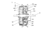
- FIG. 1 is a cross-sectional view showing a drive device according to a first embodiment of the present invention.
- FIG. 2 is a schematic diagram of the topology when the drive is in first gear.
- FIG. 3 is a schematic diagram of the topology when the drive unit is in second gear.
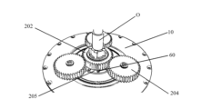
- FIG. 4 is a perspective view showing a planetary gear mechanism in the drive device.
- FIG. 5 is a perspective view showing a planetary carrier in the drive device.
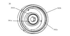
- FIG. 6 is another perspective view showing the planetary carrier in the drive device.
- FIG. 7 is a perspective view showing a clutch mechanism in the drive device.
- FIG. 8 is a perspective view showing an assembly including a clutch mechanism, a ring gear and a planetary gear in the drive device.
- FIG. 9 is a perspective view showing a state in which the sun gear is attached to the rotor holder in the drive unit.
- FIG. 10 is another perspective view showing a state in which the sun gear is attached to the rotor holder in the drive unit.
- axial direction means that two members are connected so that there is no relative movement, and includes both direct fixed connection and indirect fixed connection via another member, unless otherwise specified.
- Lock includes both direct lock and indirect lock via another member.
- Transmission connection means that two members are connected in a manner that allows torque to be transmitted, and includes direct or indirect connection of these two members.
- the drive device 1 of this embodiment is shown as a two-speed drive device including a motor M, a planetary gear mechanism 20, a clutch mechanism 30, and a housing 40.
- the motor M is an outer rotor type motor and includes a stator S, a rotor R, and a stator shaft O.
- the stator S is fixed to the stator shaft O.
- the stator shaft O is arranged along the axial direction and fixed to the vehicle to which it is to be attached.
- the rotor R is fixed to the rotor holder 10, is disposed radially outside the stator S, is arranged coaxially with the stator S, and is rotatable relative to the stator S.
- the planetary gear mechanism 20 includes a ring gear 201, a sun gear 202, a planet carrier 203, and a planetary gear 204.
- the sun gear 202 can receive torque input from the motor M.
- the ring gear 201 is fixedly connected to the wheel hub T of the vehicle to which it is attached, and outputs torque to the wheel hub T.
- the planetary gear 204 is located radially between the ring gear 201 and the sun gear 202, and meshes with the ring gear 201 and the sun gear 202, respectively.
- the clutch mechanism 30 includes a first clutch unit 301 and a second clutch unit 302.
- the planetary carrier 203 can be locked to the stator S by being locked to the stator shaft O by the first clutch unit 301.
- the planetary carrier 203 can be locked to the ring gear 201 by the second clutch unit 302. In this way, the first clutch unit 301 or the second clutch unit 302 can be selectively engaged at different gear stages.
- the first clutch unit 301 and the second clutch unit 302 each have inner rings 301a, 302a and outer rings 301b, 302b.
- the inner rings 301a, 302a and the outer rings 301b, 302b cannot rotate relative to each other.
- the inner rings 301a, 302a and the outer rings 301b, 302b can rotate relative to each other.
- the inner rings 301a, 302a can be coupled to the outer rings 301b, 302b via an intermediate member (not shown), thereby locking the inner rings 301a, 302a and the outer rings 301b, 302b.
- the housing 40 is formed by assembling a first member 401 and a second member 402 together.
- the housing 40 is fixed to the ring gear 201 and rotates together with the ring gear 201.
- the motor M, the planetary gear mechanism 20, and the clutch mechanism 30 are housed inside the housing 40.
- the planetary carrier 203 functions as the outer ring 301b of the first clutch unit 301, and further functions as the inner ring 302a of the second clutch unit 302. More specifically, the planetary carrier 203 includes an outer wall surface 54a and an inner wall surface 55a.
- the outer wall surface 54a functions as the inner ring contact surface of the second clutch unit 302.
- the inner wall surface 55a functions as the outer ring contact surface of the first clutch unit 301.
- the sun gear 202 is attached to the rotor holder 10 and fixedly connected to the rotor R of the motor M.
- the planetary gears 204 are uniformly distributed around the axis of the planetary carrier 203 and are rotatably attached to the planetary carrier 203. In this embodiment, as shown in Figures 4 and 8 to 9, the three planetary gears 204 are arranged at equal intervals in the circumferential direction around the sun gear 202.
- the motor M is arranged axially aligned with the planetary gear mechanism 20.
- the ring gear 201, sun gear 202, planetary carrier 203, and rotor holder 10 are arranged coaxially.
- both the first clutch unit 301 and the second clutch unit 302 are one-way clutches.
- a one-way clutch is a clutch in which, when one of the inner and outer rings is an active part that is connected to the motor M and the other of the inner and outer rings is a passive part, the clutch is in a coupled state only when the rotor R of the motor M rotates in one direction, and is capable of transmitting torque from the one to the other, but is in a separated state when the rotor R changes direction and rotates in the other direction, and is unable to transmit torque from the one to the other.
- the ring gear 201 rotates to the other side in the circumferential direction at a predetermined reduction ratio (gear ratio), for example 2.95, i.e., the rotational speed of the sun gear 202, which is the input element, is 2.95 times the rotational speed of the ring gear 201, which is the output element.
- a predetermined reduction ratio for example 2.95, i.e., the rotational speed of the sun gear 202, which is the input element, is 2.95 times the rotational speed of the ring gear 201, which is the output element.
- the reduction ratio is 1, that is, the rotational speed of the sun gear 202, which is the input element, is the same as the rotational speed of the planetary carrier 203 and ring gear 201, which are the output elements.
- the first clutch unit 301 and the second clutch unit 302 are each a sprag-type one-way clutch (the intermediate members are sprags), and torque is transmitted between the inner rings 301a, 302a and the outer rings 301b, 302b of the first clutch unit 301 and the second clutch unit 302 by sprags provided between the inner rings 301a, 302a and the outer rings 301b, 302b of the first clutch unit 301 and the second clutch unit 302.
- the planetary carrier 203 includes a first plate portion 51 and a second plate portion 52 perpendicular to the axial direction.
- the first plate portion 51 and the second plate portion 52 are both formed in a hollow annular shape, are arranged coaxially with each other, and are arranged at an interval in the axial direction.
- the radius of the first plate portion 51 is larger than the radius of the second plate portion 52.
- Three connecting walls 53 are formed between the first plate portion 51 and the second plate portion 52.
- the connecting walls 53 rise from the radial outer edge of the second plate portion 52 toward the first plate portion 51.
- the three connecting walls 53 are arranged at equal intervals in the circumferential direction.
- An accommodation portion is formed between the connecting walls 53.
- the height (axial length) of the connecting walls 53 is larger than the thickness of the planetary gear 204.
- Through holes 511, 521 are formed at positions corresponding to the respective accommodation portions of the first plate portion 51 and the second plate portion 52.
- the three planetary gears 204 are rotatably housed in the housing by the shafts provided in the through holes 511 and 521, and are rotatably arranged between the first plate portion 51 and the second plate portion 52.
- an outer wall portion 54 and an inner wall portion 55 are formed rising up on the opposite side of the first plate portion 51 to the second plate portion 52. That is, the outer wall portion 54 and the inner wall portion 55 are formed on the axially opposite side of the first plate portion 51 from the second plate portion 52.
- the outer wall portion 54 and the inner wall portion 55 are formed around the entire circumference.
- the outer wall portion 54 is provided slightly radially inward from the radial outer end edge of the first plate portion 51, so that a step is formed between the outer wall surface 54a of the outer wall portion 54 and the outer peripheral surface of the first plate portion 51.
- the inner wall portion 55 rises up from the radial inner side of the outer wall portion 54, more specifically, from the radial inner end edge of the first plate portion 51.
- the outer wall portion 54 and the inner wall portion 55 have a predetermined thickness and height.
- a groove 56 is formed around the entire circumference between the outer wall 54 and the inner wall 55.
- the inner ring 301a of the first clutch unit 301 is fixed to the stator shaft O of the motor M at an axial position corresponding to the inner wall portion 55 of the first plate portion 51.
- the outer peripheral surface of the inner ring 301a of the first clutch unit 301 faces the inner wall surface 55a of the inner wall portion 55.
- the inner wall portion 55 functions as the outer ring 301b of the first clutch unit 301.
- a plurality of grooves for accommodating pins are formed on the inner peripheral surface of the inner ring 301a of the first clutch unit 301, and the inner ring 301a of the first clutch unit 301 can be fixed circumferentially to the stator shaft O by a pin member or a flat key member.
- a female spline may be provided on the inner peripheral surface of the inner ring 301a and a male spline may be provided on the outer peripheral surface of the stator shaft O, and the inner ring 301a of the first clutch unit 301 may be fixed circumferentially to the stator shaft O by engaging the female spline with the male spline.
- the outer ring 302b of the second clutch unit 302 is fixed to the housing 40 at an axial position corresponding to the outer wall portion 54 of the first plate portion 51.
- the inner peripheral surface of the outer ring 302b of the second clutch unit 302 faces the outer wall surface 54a of the outer wall portion 54.
- the outer wall portion 54 functions as the inner ring 302a of the second clutch unit 302.
- the outer peripheral surface of the outer ring 302b of the second clutch unit 302 is formed with a plurality of grooves for accommodating pin members, flat key members, or splines.
- the outer ring 302b of the second clutch unit 302 is fixed to the housing 40 in the circumferential direction by the pin members or flat key members.
- a male spline may be provided on the outer peripheral surface of the outer ring 302b
- a female spline may be provided on the housing 40
- the outer ring 302b of the second clutch unit 302 may be fixed to the housing 40 in the circumferential direction by engaging the female spline with the male spline.
- the sun gear 202 and the rotor holder 10 are fixed by bolts 60.
- the sun gear 202 and the rotor holder 10 are aligned in the axial direction, and an annular mounting plate 205 is formed on the motor M side of the sun gear 202, and the mounting plate 205 is formed integrally with the sun gear 202.
- a plurality of through holes are formed in the mounting plate 205.
- the rotor holder 10 is disk-shaped.
- a plurality of through holes are also formed in corresponding positions of the rotor holder 10, and the sun gear 202 and the rotor holder 10 are fixed coaxially by passing the bolts 60 through the through holes of the sun gear 202 and the rotor holder 10.
- the outer ring 302b of the second clutch unit 302 and the first member 401 of the housing 40 can first be combined into an assembly, and then the inner ring 301a of the first clutch unit 301, the planetary gear mechanism 20, and the second member 402 of the housing 40 can be combined into an assembly, and then the two assemblies can be assembled.
- the present embodiment further provides a vehicle including the drive unit 1.
- the vehicle may in particular be a vehicle having at least two or more wheels, with the drive unit 1 being attached to at least one of the wheels.
- the drive unit 1 is a two-speed drive unit.
- the drive unit 1 only needs to have at least two gears, and clutch units may be added according to the number of gears.
- first clutch unit 301 and the second clutch unit 302 are both one-way clutches, but it goes without saying that the first clutch unit 301 and the second clutch unit 302 may be other types of clutches, such as a two-way clutch.
- connection or disconnection of the outer and inner rings of the clutch can be controlled by a control mechanism.
- the one-way clutch is a sprag-type one-way clutch, but it goes without saying that it may be any of various known one-way clutches, such as a ratchet-ratchet type one-way clutch or a roller type one-way clutch. Accordingly, the sprags may be replaced with other types of intermediate members.
- the inner ring 301a of the first clutch unit 301 is fixed to the stator shaft O of the motor M to lock the planetary carrier 203 and the stator shaft O, but it goes without saying that the inner ring 301a of the first clutch unit 301 may also be fixed to another member that does not move relative to the mounting object.
- the planetary carrier 203 functions as the outer ring 301b of the first clutch unit 301 and as the inner ring 302a of the second clutch unit 302, but it goes without saying that the planetary carrier 203 may function as either the outer ring 301b of the first clutch unit 301 or the inner ring 302a of the second clutch unit 302.
- the planetary gear mechanism 20 has three planetary gears 204, but the number of planetary gears 204 is not limited to this and may be four or more.
- the motor M is an outer rotor type motor, but is not limited to this and may be an inner rotor type motor.
- the reduction ratio is 2.95 when in first gear, but it is not limited to this and the reduction ratio can be adjusted by setting a different gear ratio.
- the outer wall portion 54 and the inner wall portion 55 are spaced apart in the radial direction, and a groove portion 56 is formed between them, but this is not limited to the above, and the outer wall portion 54 and the inner wall portion 55 do not have to be spaced apart in the radial direction, or may be connected via another wall portion rising from the first plate portion 51.
- the sun gear 202 and the rotor holder 10 are fixed coaxially by the bolts 60, but this is not limited thereto, and they may be fixed by other means such as welding, press fitting, or adhesive.
Landscapes
- Engineering & Computer Science (AREA)
- Chemical & Material Sciences (AREA)
- Combustion & Propulsion (AREA)
- Mechanical Engineering (AREA)
- Transportation (AREA)
- General Engineering & Computer Science (AREA)
- Retarders (AREA)
- Connection Of Motors, Electrical Generators, Mechanical Devices, And The Like (AREA)
Priority Applications (1)
| Application Number | Priority Date | Filing Date | Title |
|---|---|---|---|
| JP2025510990A JPWO2024204288A1 (https=) | 2023-03-30 | 2024-03-27 |
Applications Claiming Priority (2)
| Application Number | Priority Date | Filing Date | Title |
|---|---|---|---|
| CN202310328962.9A CN118722200A (zh) | 2023-03-30 | 2023-03-30 | 驱动装置及车辆 |
| CN202310328962.9 | 2023-03-30 |
Publications (1)
| Publication Number | Publication Date |
|---|---|
| WO2024204288A1 true WO2024204288A1 (ja) | 2024-10-03 |
Family
ID=92851908
Family Applications (1)
| Application Number | Title | Priority Date | Filing Date |
|---|---|---|---|
| PCT/JP2024/012133 Ceased WO2024204288A1 (ja) | 2023-03-30 | 2024-03-27 | 駆動装置及び車両 |
Country Status (3)
| Country | Link |
|---|---|
| JP (1) | JPWO2024204288A1 (https=) |
| CN (1) | CN118722200A (https=) |
| WO (1) | WO2024204288A1 (https=) |
Citations (4)
| Publication number | Priority date | Publication date | Assignee | Title |
|---|---|---|---|---|
| JPS5171486U (https=) * | 1974-12-02 | 1976-06-05 | ||
| US20080179119A1 (en) * | 2007-01-31 | 2008-07-31 | Grenn Daniel P | Vehicle drive system, power management device, and method for managing power |
| JP2013036539A (ja) * | 2011-08-08 | 2013-02-21 | Suzuki Motor Corp | オイルポンプの駆動装置 |
| WO2013128647A1 (ja) * | 2012-03-02 | 2013-09-06 | トヨタ自動車株式会社 | 車両用駆動装置 |
-
2023
- 2023-03-30 CN CN202310328962.9A patent/CN118722200A/zh active Pending
-
2024
- 2024-03-27 WO PCT/JP2024/012133 patent/WO2024204288A1/ja not_active Ceased
- 2024-03-27 JP JP2025510990A patent/JPWO2024204288A1/ja active Pending
Patent Citations (4)
| Publication number | Priority date | Publication date | Assignee | Title |
|---|---|---|---|---|
| JPS5171486U (https=) * | 1974-12-02 | 1976-06-05 | ||
| US20080179119A1 (en) * | 2007-01-31 | 2008-07-31 | Grenn Daniel P | Vehicle drive system, power management device, and method for managing power |
| JP2013036539A (ja) * | 2011-08-08 | 2013-02-21 | Suzuki Motor Corp | オイルポンプの駆動装置 |
| WO2013128647A1 (ja) * | 2012-03-02 | 2013-09-06 | トヨタ自動車株式会社 | 車両用駆動装置 |
Also Published As
| Publication number | Publication date |
|---|---|
| JPWO2024204288A1 (https=) | 2024-10-03 |
| CN118722200A (zh) | 2024-10-01 |
Similar Documents
| Publication | Publication Date | Title |
|---|---|---|
| EP3828437B1 (en) | Multi-speed gearbox and the drive axle made therewith | |
| CN110091702B (zh) | 动力传递装置 | |
| CN110088504B (zh) | 尤其用于电驱动用途的可换挡两档变速器 | |
| CA2978224C (en) | Gearing assembly, vehicle drivetrain and electric wheel hub therewith | |
| US9890845B2 (en) | Transmission | |
| JP5200532B2 (ja) | 変速装置 | |
| JPWO2020105635A1 (ja) | 車両用駆動装置 | |
| EP4145017B1 (en) | Gear assembly for use in electric drive transmissions | |
| EP3740701B1 (en) | Gearing assembly and gearing apparatus | |
| US12270463B1 (en) | Electric drive system for a motor vehicle | |
| CN105899848A (zh) | 用于前进档/倒档行星齿轮组的多模式离合器行星齿轮组 | |
| KR20260012772A (ko) | 차동 장치 분리 시스템 | |
| WO2017094796A1 (ja) | 伝動装置及び差動装置 | |
| US9371871B2 (en) | Freewheel device with switchable freewheel | |
| WO2024204288A1 (ja) | 駆動装置及び車両 | |
| JP7218732B2 (ja) | 動力伝達装置 | |
| CN112757896B (zh) | 车桥系统 | |
| JP2011132977A5 (https=) | ||
| JP5270382B2 (ja) | 車両の駆動装置 | |
| JP2026007480A (ja) | 動力伝達装置 | |
| JPWO2024204288A5 (https=) | ||
| WO2025204203A1 (ja) | 駆動装置及び車両 | |
| WO2024204289A1 (ja) | 駆動装置及び車両 | |
| JP2004346955A (ja) | 車両用動力伝達装置 | |
| JP2024010429A (ja) | 車両用駆動伝達装置 |
Legal Events
| Date | Code | Title | Description |
|---|---|---|---|
| 121 | Ep: the epo has been informed by wipo that ep was designated in this application |
Ref document number: 24776831 Country of ref document: EP Kind code of ref document: A1 |
|
| ENP | Entry into the national phase |
Ref document number: 2025510990 Country of ref document: JP Kind code of ref document: A |
|
| WWE | Wipo information: entry into national phase |
Ref document number: 2025510990 Country of ref document: JP |
|
| WWE | Wipo information: entry into national phase |
Ref document number: 202517102776 Country of ref document: IN |
|
| NENP | Non-entry into the national phase |
Ref country code: DE |
|
| WWP | Wipo information: published in national office |
Ref document number: 202517102776 Country of ref document: IN |
|
| 122 | Ep: pct application non-entry in european phase |
Ref document number: 24776831 Country of ref document: EP Kind code of ref document: A1 |