WO2024204193A1 - ウェアラブル装置および心不全検出システム - Google Patents
ウェアラブル装置および心不全検出システム Download PDFInfo
- Publication number
- WO2024204193A1 WO2024204193A1 PCT/JP2024/011938 JP2024011938W WO2024204193A1 WO 2024204193 A1 WO2024204193 A1 WO 2024204193A1 JP 2024011938 W JP2024011938 W JP 2024011938W WO 2024204193 A1 WO2024204193 A1 WO 2024204193A1
- Authority
- WO
- WIPO (PCT)
- Prior art keywords
- wearable device
- subject
- wrist
- main body
- contacts
- Prior art date
- Legal status (The legal status is an assumption and is not a legal conclusion. Google has not performed a legal analysis and makes no representation as to the accuracy of the status listed.)
- Ceased
Links
Images








Classifications
-
- A—HUMAN NECESSITIES
- A61—MEDICAL OR VETERINARY SCIENCE; HYGIENE
- A61B—DIAGNOSIS; SURGERY; IDENTIFICATION
- A61B7/00—Instruments for auscultation
- A61B7/02—Stethoscopes
- A61B7/04—Electric stethoscopes
-
- A—HUMAN NECESSITIES
- A61—MEDICAL OR VETERINARY SCIENCE; HYGIENE
- A61B—DIAGNOSIS; SURGERY; IDENTIFICATION
- A61B10/00—Instruments for taking body samples for diagnostic purposes; Other methods or instruments for diagnosis, e.g. for vaccination diagnosis, sex determination or ovulation-period determination; Throat striking implements
-
- A—HUMAN NECESSITIES
- A61—MEDICAL OR VETERINARY SCIENCE; HYGIENE
- A61B—DIAGNOSIS; SURGERY; IDENTIFICATION
- A61B5/00—Measuring for diagnostic purposes; Identification of persons
-
- A—HUMAN NECESSITIES
- A61—MEDICAL OR VETERINARY SCIENCE; HYGIENE
- A61B—DIAGNOSIS; SURGERY; IDENTIFICATION
- A61B5/00—Measuring for diagnostic purposes; Identification of persons
- A61B5/01—Measuring temperature of body parts ; Diagnostic temperature sensing, e.g. for malignant or inflamed tissue
-
- A—HUMAN NECESSITIES
- A61—MEDICAL OR VETERINARY SCIENCE; HYGIENE
- A61B—DIAGNOSIS; SURGERY; IDENTIFICATION
- A61B5/00—Measuring for diagnostic purposes; Identification of persons
- A61B5/02—Detecting, measuring or recording for evaluating the cardiovascular system, e.g. pulse, heart rate, blood pressure or blood flow
-
- A—HUMAN NECESSITIES
- A61—MEDICAL OR VETERINARY SCIENCE; HYGIENE
- A61B—DIAGNOSIS; SURGERY; IDENTIFICATION
- A61B5/00—Measuring for diagnostic purposes; Identification of persons
- A61B5/02—Detecting, measuring or recording for evaluating the cardiovascular system, e.g. pulse, heart rate, blood pressure or blood flow
- A61B5/0205—Simultaneously evaluating both cardiovascular conditions and different types of body conditions, e.g. heart and respiratory condition
- A61B5/02055—Simultaneously evaluating both cardiovascular condition and temperature
-
- A—HUMAN NECESSITIES
- A61—MEDICAL OR VETERINARY SCIENCE; HYGIENE
- A61B—DIAGNOSIS; SURGERY; IDENTIFICATION
- A61B5/00—Measuring for diagnostic purposes; Identification of persons
- A61B5/02—Detecting, measuring or recording for evaluating the cardiovascular system, e.g. pulse, heart rate, blood pressure or blood flow
- A61B5/024—Measuring pulse rate or heart rate
- A61B5/02438—Measuring pulse rate or heart rate with portable devices, e.g. worn by the patient
-
- A—HUMAN NECESSITIES
- A61—MEDICAL OR VETERINARY SCIENCE; HYGIENE
- A61B—DIAGNOSIS; SURGERY; IDENTIFICATION
- A61B5/00—Measuring for diagnostic purposes; Identification of persons
- A61B5/103—Measuring devices for testing the shape, pattern, colour, size or movement of the body or parts thereof, for diagnostic purposes
- A61B5/11—Measuring movement of the entire body or parts thereof, e.g. head or hand tremor or mobility of a limb
-
- A—HUMAN NECESSITIES
- A61—MEDICAL OR VETERINARY SCIENCE; HYGIENE
- A61B—DIAGNOSIS; SURGERY; IDENTIFICATION
- A61B5/00—Measuring for diagnostic purposes; Identification of persons
- A61B5/103—Measuring devices for testing the shape, pattern, colour, size or movement of the body or parts thereof, for diagnostic purposes
- A61B5/11—Measuring movement of the entire body or parts thereof, e.g. head or hand tremor or mobility of a limb
- A61B5/1118—Determining activity level
-
- A—HUMAN NECESSITIES
- A61—MEDICAL OR VETERINARY SCIENCE; HYGIENE
- A61B—DIAGNOSIS; SURGERY; IDENTIFICATION
- A61B5/00—Measuring for diagnostic purposes; Identification of persons
- A61B5/68—Arrangements of detecting, measuring or recording means, e.g. sensors, in relation to patient
- A61B5/6801—Arrangements of detecting, measuring or recording means, e.g. sensors, in relation to patient specially adapted to be attached to or worn on the body surface
- A61B5/6802—Sensor mounted on worn items
- A61B5/681—Wristwatch-type devices
-
- A—HUMAN NECESSITIES
- A61—MEDICAL OR VETERINARY SCIENCE; HYGIENE
- A61B—DIAGNOSIS; SURGERY; IDENTIFICATION
- A61B5/00—Measuring for diagnostic purposes; Identification of persons
- A61B5/74—Details of notification to user or communication with user or patient; User input means
- A61B5/742—Details of notification to user or communication with user or patient; User input means using visual displays
-
- A—HUMAN NECESSITIES
- A61—MEDICAL OR VETERINARY SCIENCE; HYGIENE
- A61B—DIAGNOSIS; SURGERY; IDENTIFICATION
- A61B7/00—Instruments for auscultation
-
- A—HUMAN NECESSITIES
- A61—MEDICAL OR VETERINARY SCIENCE; HYGIENE
- A61B—DIAGNOSIS; SURGERY; IDENTIFICATION
- A61B2560/00—Constructional details of operational features of apparatus; Accessories for medical measuring apparatus
- A61B2560/02—Operational features
- A61B2560/0242—Operational features adapted to measure environmental factors, e.g. temperature, pollution
- A61B2560/0247—Operational features adapted to measure environmental factors, e.g. temperature, pollution for compensation or correction of the measured physiological value
- A61B2560/0252—Operational features adapted to measure environmental factors, e.g. temperature, pollution for compensation or correction of the measured physiological value using ambient temperature
-
- A—HUMAN NECESSITIES
- A61—MEDICAL OR VETERINARY SCIENCE; HYGIENE
- A61B—DIAGNOSIS; SURGERY; IDENTIFICATION
- A61B2562/00—Details of sensors; Constructional details of sensor housings or probes; Accessories for sensors
- A61B2562/02—Details of sensors specially adapted for in-vivo measurements
- A61B2562/0204—Acoustic sensors
-
- A—HUMAN NECESSITIES
- A61—MEDICAL OR VETERINARY SCIENCE; HYGIENE
- A61B—DIAGNOSIS; SURGERY; IDENTIFICATION
- A61B2562/00—Details of sensors; Constructional details of sensor housings or probes; Accessories for sensors
- A61B2562/02—Details of sensors specially adapted for in-vivo measurements
- A61B2562/0219—Inertial sensors, e.g. accelerometers, gyroscopes, tilt switches
-
- A—HUMAN NECESSITIES
- A61—MEDICAL OR VETERINARY SCIENCE; HYGIENE
- A61B—DIAGNOSIS; SURGERY; IDENTIFICATION
- A61B2562/00—Details of sensors; Constructional details of sensor housings or probes; Accessories for sensors
- A61B2562/02—Details of sensors specially adapted for in-vivo measurements
- A61B2562/028—Microscale sensors, e.g. electromechanical sensors [MEMS]
Definitions
- the present invention relates to a wearable device for collecting heart sounds.
- Avoiding readmission depends on how reliably the patient's cardiac condition is monitored after discharge, and how early recurrence is detected and intervention is performed.
- the cardiac monitoring device described in Patent Document 1 includes an enclosure with various sensors and components.
- the top surface of the enclosure has a first groove sized to fit the phalanges of the subject's right hand.
- the cardiac monitoring device is oriented appropriately to record the subject's cardiac activity.
- the cardiac monitoring device includes a plurality of electrodes configured to create an electrical circuit through one or more human hearts.
- the plurality of electrodes includes a right thumb electrode located on a side of the enclosure that connects to the thumb of the subject's right hand, and upper and lower chest electrodes located on a bottom surface of the enclosure that connect to the subject's chest.
- the cardiac monitoring device also has a plurality of pulse oximeters configured to measure the blood oxygen level of the corresponding phalanges located in the first groove.
- the heart rate monitor described in Patent Document 2 is hung around the subject's neck like a pendant and measures the heart rate near the chest.
- the heart rate monitor described in Patent Document 3 is a wristwatch-type heart rate monitor with a microphone attached to the wristband.
- CardioMEMS HF System https://www.cardiovascular.abbott/us/en/hcp/products/heart-failure/pulmonary-pressure-monitors/cardiomems/about.html, retrieved on March 11, 2023
- JP 2021-501029 A Japanese Patent Application Publication No. 2-74232 Japanese Patent Application Publication No. 5-29686
- Non-Patent Document 1 the conventional monitoring method described in Non-Patent Document 1 involves implanting a device in the patient's pulmonary artery. In other words, it is invasive. This places a burden on the patient's body and requires a lot of effort from the doctor. There are also problems with the high cost and the fact that measurements can only be taken on a special bed sensor. Also, the device or heart rate monitor described in Patent Document 1 is less reliable in obtaining heart sounds.
- the present invention aims to provide an inexpensive means for monitoring the cardiac condition of a patient or other subject in a less invasive manner than conventional methods, without significantly compromising the reliability of obtaining heart sounds.
- a wearable device is a wearable device that is worn on the wrist of a subject, in which a sound collection unit for acquiring the subject's heart sounds is disposed on the top surface of the body of the wearable device, and an operation unit through which the subject performs operations to acquire the heart sounds is disposed on the side of the body along the longitudinal direction of the subject's arm when the device is worn on the wrist.
- the sound collection unit has a microphone made of rubber and a piezoelectric element, the surface of the rubber forms part of the upper surface, and the microphone is placed in contact with the back surface of the rubber.
- the present invention provides an inexpensive means for monitoring the cardiac condition of a patient or other subject in a less invasive manner than conventional methods.
- FIG. 1 is a diagram illustrating an example of the overall configuration of a heart failure detection system.
- FIG. 2 is a perspective view of a wearable device.
- FIG. 2 is a diagram showing an example of how the wearable device 2 is worn in normal circumstances.
- 1A and 1B are diagrams illustrating an example of how the wearable device 2 is worn when collecting heart sounds.
- FIG. 2 is an exploded view of the wearable device.
- 1A-1C are third angle views of an example of the top, bottom, and three side views of a wearable device.
- FIG. 2 is a diagram illustrating an example of hardware implementation on a main board.
- FIG. 13 is a diagram illustrating an example of the configuration of an observation support program.
- FIG. 13 is a diagram showing an example of control of three light emitters for each state.
- FIG. 2 is a diagram showing an example of a waveform of a heart sound.
- 13 is a flowchart illustrating an example of an overall processing flow by the observation support program.
- 13 is a flowchart illustrating an example of an overall processing flow by the observation support program.
- FIG. 13 is a diagram showing a first modified example of a wearable device.
- FIG. 13 is a diagram showing a second modified example of a wearable device.
- 13A and 13B are diagrams showing modified examples of the arrangement of three contacts.
- FIG. 1 is a diagram illustrating an example of the appearance of a wearable device.
- 1A and 1B are diagrams showing examples of the appearance of the upper and lower sides of a device main body.
- 1A to 1C are diagrams illustrating examples of the appearance of the side and bottom sides of a wearable device.
- 4A and 4B are a front view and a perspective view of a connecting member;
- FIG. 1 shows examples of female and male parts.
- 1A to 1C are diagrams illustrating examples of the appearance of the top and bottom sides of a wearable device.
- FIG. 1 is a diagram showing an example of the overall configuration of a heart failure detection system 1.
- Fig. 2 is a perspective view of a wearable device 2.
- Fig. 3 is a diagram showing an example of how the wearable device 2 is worn in normal times.
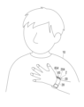
- Fig. 4 is a diagram showing an example of how the wearable device 2 is worn when collecting heart sounds.
- the heart failure detection system 1 is a system for detecting heart failure in a subject 10, and as shown in FIG. 1, is composed of a wearable device 2, a relay device 3, a heart failure detection server 40, a medical personnel terminal 41, and a communication line 5.
- the wearable device 2 is a wristwatch-type device for recording the heart sounds of the subject 10, and has a device body 20 and a wristband 28 as shown in FIG. 2.
- the subject 10 wears the wearable device 2 on his/her wrist all day, in principle. It can be worn on either the left or right wrist, but it is preferable to wear it so that the user interface unit 65 and the display sticker 625 are located on the thumb side when the device main body 20 is on the palm side.
- the subject 10 wears the wearable device 2 so that the device body 20 is located on the back of the hand as shown in Figure 3.
- the subject moves the device body 20 around towards the palm of the hand and presses it against the chest near the heart as shown in Figure 4. It is also acceptable to wear the wearable device 2 so that the device body 20 is located on the palm even when not recording.
- the wearable device 2 and relay device 3 communicate with each other via short-range wireless communication such as Bluetooth.
- the relay device 3 receives heart sounds and other data recorded by the wearable device 2 from the wearable device 2 and transfers them to the heart failure detection server 40 via the communication line 5.
- a portable device having short-range wireless communication and IP (Internet Protocol) communication functions such as a smartphone or tablet computer, is used.
- the communication line 5 is an IP communication network such as an Internet line or a LAN line.
- the heart failure detection server 40 detects heart failure in the subject 10 by analyzing the heart sounds transferred from the relay device 3.
- a so-called server machine or cloud server is used as the heart failure detection server 40.
- the medical personnel terminal 41 is a terminal device used by the medical personnel in charge of the subject 10.
- a personal computer, a smartphone, a tablet computer, or the like is used as the medical personnel terminal 41.
- FIG. 5 is an exploded view of the wearable device 2.
- Fig. 6 is a third angle projection view showing an example of the upper surface 201, the lower surface 202, and three side surfaces 203 to 205 of the wearable device 2.
- Fig. 7 is a view showing an example of hardware implementation on the main board 61.
- FIG. 6 a front view is shown in the center, a top view and a bottom view are shown above and below, respectively, and a left side view and a right side view are shown to the left and right of that, respectively. Note that the wristband 28 is omitted from the bottom view.
- the device main body 20 is composed of a cabinet 60, a main board 61, a sound collection unit 62, a speaker 63, a skin temperature measurement unit 64, a user interface unit 65, an ambient temperature measurement unit 66, and a secondary battery 67.
- the cabinet 60 is the housing of the device main body 20, and is composed of a top cabinet 601, a bottom cabinet 602, and four screws 603 as shown in FIG. 5.
- the bottom cabinet 602 is fixed to the top cabinet 601 by the screws 603.
- the space between the top cabinet 601 and the bottom cabinet 602 contains a main board 61, a speaker 63, a skin temperature measuring unit 64, a user interface unit 65, an ambient temperature measuring unit 66, and a secondary battery 67.
- a main board 61 The space between the top cabinet 601 and the bottom cabinet 602 contains a main board 61, a speaker 63, a skin temperature measuring unit 64, a user interface unit 65, an ambient temperature measuring unit 66, and a secondary battery 67.
- some components protrude slightly from the top cabinet 601 or the bottom cabinet 602.
- the main board 61 is fixed to the top cabinet 601 by three sets of screws 616 and washers 617.
- the main board 61 is equipped with a CPU (Central Processing Unit) 611, main memory 612, non-volatile memory 613, a three-axis acceleration sensor 614, and a wireless communication circuit 615, as shown in FIG. 7.
- CPU Central Processing Unit
- An observation support program 68 is installed in the non-volatile memory 613.
- the observation support program 68 is loaded into the main memory 612 and executed by the CPU 611.
- the three-axis acceleration sensor 614 is used to measure the activity of the subject 10.
- the wireless communication circuit 615 is used to wirelessly communicate with the wearable device 2.
- the sound collection unit 62 is composed of a microphone 621, double-sided tape 622, rubber 623, a cover 624, and a display sticker 625.
- the microphone 621 is fixed with double-sided tape 622 in a recess 601e provided in the center of the upper surface 6011 of the top cabinet 601.
- a circular piezoelectric element with a diameter of about 20 mm is used as the microphone 621.
- Piezoelectric elements are sold under names such as “piezoelectric sheet,” “piezoelectric microphone,” “piezoelectric film,” or “piezoelectric buzzer.”
- a hole is provided near the center of the bottom surface of the recess 601e, and an electric wire connecting the microphone 621 and the main board 61 passes through this hole.
- the rubber 623 is a circular, thin rubber membrane that is provided on the part that corresponds to the dial of a wristwatch. More specifically, the bottom surface 6232 is positioned so that it contacts and covers the microphone 621.
- the top surface 6231 of the rubber 623 is exposed on the top surface 6011 of the top cabinet 601, and when recording heart sounds, the top surface 6231 is pressed against the chest of the subject 10. In this way, the rubber 623 functions to transmit the heart sounds to the microphone 621.
- the top surface 6231 of the rubber 623 has an end (periphery) cut out, and a step is formed to fit into the hole 6241 of the lid 624.
- the microphone 621 and rubber 623 are attached to the top of the top cabinet 601 and closed by a lid 624.
- the lid 624 has a hole 6241 into which the top of the rubber 623 is fitted. This causes the top of the rubber 623 to protrude slightly outside the lid 624.
- the display sticker 625 has the main role of each of the blue, green, and orange colors emitted by the light emitters of the user interface unit 65 printed on it, and is attached to the user interface unit 65 side of the top surface of the lid 624.
- the speaker 63 outputs sounds such as beeps.
- a piezoelectric element is used as the speaker 63.
- the skin temperature measuring unit 64 is composed of a skin temperature measuring substrate 641, a first contact 6421, a second contact 6422, a third contact 6423, Kapton tape 643, contact tapes 6441-6443, a spacer 645, and a battery tape 646, and measures the temperature of each of three points on the skin of the subject 10's wrist.
- Kapton is a registered trademark of DuPont.
- the first contact 6421, the second contact 6422, and the third contact 6423 are probes that come into contact with the skin and are connected to the skin temperature measurement substrate 641 via the Kapton tape 643 and the contact tapes 6441 to 6443.
- the bottom surface of the bottom cabinet 602 has three holes on a straight line perpendicular to the longitudinal direction of the subject's 10 arm when the device is worn by the subject 10.
- the diameters of the first contact 6421, the second contact 6422, the third contact 6423, and each hole are all approximately 6 mm, and the distance between two adjacent holes is approximately 2 mm.
- the distance between two adjacent contacts is also similar. Therefore, the distance between the centers of two adjacent contacts is approximately 8 mm.
- the first contact 6421, the second contact 6422, and the third contact 6423 are fitted into each hole and protrude slightly outside the bottom cabinet 602.
- the skin temperature measurement substrate 641 is fixed to the secondary battery 67 via a spacer 645 and battery tape 646.
- the skin temperature measurement board 641 is equipped with sensors and circuits for measuring the temperature of the heat transferred from the first contact 6421, the second contact 6422, and the third contact 6423. This allows the temperature of each of the three points on the skin of the subject 10's wrist to be measured. Each measurement value is provided to the CPU 611.
- the user interface unit 65 is composed of a side key board 651, a blue light guide pin 6521, a green light guide pin 6522, an orange light guide pin 6523, a light shielding block 653, a start key 654, a side key holder 655, a side key board tape 656, a side key holder tape 657, and two screws 658.
- the side key board 651 is equipped with a blue light-emitting element 6511, a green light-emitting element 6512, an orange light-emitting element 6513, and a switch 6514.
- the blue light-emitting element 6511, the green light-emitting element 6512, and the orange light-emitting element 6513 are LEDs (Light Emitting Diodes) that emit blue, green, and orange light, respectively.
- the blue light emitter 6511 conveys the status regarding acquisition of heart sounds and body temperature.
- the green light emitter 6512 conveys the status regarding communication with the relay device 3.
- the orange light emitter 6513 conveys the status regarding charging.
- the start key 654 is a cylindrical button, and its back surface can come into contact with the operation portion of the switch 6514.
- one side surface 204 is provided with holes 601a-601c and hole 601d.
- the start key 654 fits into hole 601d from the inside, and the surface of the start key 654 protrudes slightly to the outside of the top cabinet 601.
- the side surface 204 is sometimes referred to as the "operation surface 204".
- the blue light guide pin 6521, the green light guide pin 6522, and the orange light guide pin 6523 are light-transmitting pins, and are arranged to contact the blue light emitter 6511, the green light emitter 6512, and the orange light emitter 6513, respectively.
- the light-shielding block 653 is a block that blocks light, but has three holes 653a, 653b, and 653c, into which the blue light-guiding pin 6521, the green light-guiding pin 6522, and the orange light-guiding pin 6523 fit and are held, respectively.
- the ends of the blue light-guiding pin 6521, the green light-guiding pin 6522, and the orange light-guiding pin 6523 are visible from the holes 601a, 601b, and 601c in the top cabinet 601.
- the blue light emitter 6511, the green light emitter 6512, and the orange light emitter 6513 emit light
- the blue, green, and orange light reach the outside of the device body 20 through the blue light guiding pin 6521, the green light guiding pin 6522, and the orange light guiding pin 6523, respectively. This allows the subject 10 to confirm the light of each color.
- the side key board 651 is fitted into the side key holder 655.
- the side key board tape 656 securely fixes the side key board 651 to the side key holder 655.
- the side key holder tape 657 and the screws 658 fix the side key holder 655 to the top cabinet 601.
- the ambient temperature measurement unit 66 is composed of an ambient temperature measurement board 661, a spacer 662, and a spacer tape 663.
- the ambient temperature measurement board 661 is equipped with a sensor and circuitry that measures the temperature around the wearable device 2. When the subject 10 is inside a room, the temperature of the room (room temperature) is measured, and when the subject 10 is outside, the outside temperature is measured.
- the ambient temperature measurement board 661 is attached to the main board 61 via a spacer 662.
- the spacer tape 663 fixes the spacer 662 to the ambient temperature measurement board 661.
- the secondary battery 67 supplies power to each part of the device main body 20. It is also connected to a USB power source and charged via a USB (Universal Serial Bus) cable or the like that is inserted into the USB connector 671 (see Figure 6) on the side surface 205.
- USB Universal Serial Bus
- the device main body 20 is provided with a circuit for controlling the supply of power from the secondary battery 67 to each part, a circuit for controlling charging of the secondary battery 67, and a circuit for exchanging signals between each part.
- the wristband 28 secures the device body 20 to the wrist of the subject 10 by wrapping it around the wrist of the subject 10.
- a commercially available wristwatch band may be used as the wristband 28.
- the position of the device body 20 is changed when recording heart sounds, so in order to make it easier to move the device body 20, it is preferable to use an elastic band, such as a rubber band or a nylon band, as the wristband 28.
- an elastic band such as a rubber band or a nylon band
- Other materials that may be used include leather bands, steel bands, silicone bands, synthetic resin bands, and canvas bands.
- Fig. 8 is a diagram showing an example of the configuration of the observation support program 68.
- Fig. 9 is a diagram showing an example of control of three light emitters for each state.
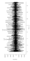
- Fig. 10 is a diagram showing an example of the waveform of heart sounds.
- the observation support program 68 is composed of modules such as a connection module 71, a heart sound acquisition module 72, a skin temperature acquisition module 73, an ambient temperature acquisition module 74, a heart sound temperature transmission module 75, an acceleration acquisition module 76, an acceleration transmission module 77, and a battery status notification module 78. These modules execute the following processes (1) to (3). By executing these modules, the blue light-emitting element 6511, the green light-emitting element 6512, and the orange light-emitting element 6513 are controlled as shown in FIG. 9.
- the subject 10 When starting recording, the subject 10 first moves the device main body 20 towards the palm side as shown in FIG. 4. Then, the subject inputs a connection command by pressing the start key 654 with the hand that is not wearing the wearable device 2. If the device main body 20 is in sleep mode, the subject must first cancel the sleep mode by pressing and holding the start key 654 before inputting the connection command.
- connection command When a connection command is input, the connection command is provided from the side key board 651 to the CPU 611. The CPU 611 then executes the following process to connect the wearable device 2 and the relay device 3 so that they can communicate with each other using the connection module 71.
- the CPU 611 starts blinking the green light emitter 6512 at 1/2 second intervals. In other words, it alternates between turning it on for 1/4 second and off for 1/4 second.
- the CPU 611 also transmits an advertising packet via the wireless communication circuit 615 in parallel with the blinking.
- the relay device 3 receives this packet, it transmits a connection request to the wearable device 2.
- the CPU 611 establishes a connection with the relay device 3.
- an encryption key is used. Note that if the wearable device 2 has not yet been paired with the relay device 3, the CPU 611 performs processing for pairing with the relay device 3 before establishing a connection, and generates an encryption key.
- the subject 10 visually confirms that the blinking cycle of the green light-emitting element 6512 has changed from 1/2 second to 1/4 second, he or she presses the device main body 20 against a specified position on their chest. More specifically, if the wearable device 2 is worn on the left wrist, the subject presses the left palm against the center of the anterior chest. Then, the subject presses the switch 6514 once more to input the recording command.
- the recording command is sent from the side key board 651 to the CPU 611.
- the CPU 611 then executes processing to acquire information such as the heart sounds of the subject 10 using the heart sound acquisition module 72, skin temperature acquisition module 73, and ambient temperature acquisition module 74.
- the recording command and the connection command can be distinguished depending on whether or not a connection with the relay device 3 has been established. In other words, if a connection has not been established, the command from the side key board 651 is a connection command, and if a connection has been established, it is a recording command.
- the heart sound acquisition module 72 performs the process of acquiring heart sounds as follows.
- the CPU 611 turns on the microphone 621 so that sound collection begins.
- the audio signal of the heart sounds collected by the microphone 621 is then sampled and quantized (A/D converted) and stored as audio data in the main memory 612 or non-volatile memory 613.
- the green light emitter 6512 continues to blink at a 1/4 second cycle, and the orange light emitter 6513 remains off.
- a predetermined time e.g. 15 seconds
- the microphone 621 is turned off, and the audio data stored in the main memory 612 or non-volatile memory 613 at this predetermined time is converted into a file.
- the audio file 80 may be an uncompressed file such as a WAV file, or a compressed file such as an MP3 file.
- a separate audio processing circuit may be provided to generate the audio file 80.
- the process for acquiring the skin surface temperature Ts of the wrist of the subject 10 is carried out as follows.
- the CPU 611 instructs the skin temperature measurement unit 64 to take a temperature.
- the skin temperature measurement unit 64 measures the temperature of each of the three points on the wrist of the subject 10 where the first contact 6421, the second contact 6422, and the third contact 6423 (see FIG. 6) are in contact, and the respective measured values T1, T2, and T3 are provided from the skin temperature measurement unit 64 to the CPU 611.
- the major blood vessel is the radial vein, which runs near the surface of the palm side of the human wrist.
- the area of the skin on the palm side of the human wrist near the radial vein is more susceptible to the influence of blood than other areas, and therefore has a higher temperature. Therefore, in order to obtain a more accurate measurement of the temperature of the skin on the wrist of the subject 10, it is desirable to have the three contacts (first contact 6421, second contact 6422, third contact 6423) of the skin temperature measuring unit 64 not come into contact with this area, but rather come into contact with other areas.
- one or more of the contacts may come into contact with this nearby area.
- the skin temperature measuring unit 64 is configured so that when worn on the wrist, the three contacts are aligned in a straight line in the width direction (circumferential direction) of the wrist, and the distance between the centers of two adjacent contacts is approximately 8 millimeters. This configuration makes it possible to limit the number of contacts that come into contact with this nearby area to at most one.
- the CPU 611 performs the following calculation.
- the CPU 611 detects abnormal values from among the three measured values T1, T2, and T3. Specifically, it compares the measured values T1 and T2 with each other, and if the difference between the two is equal to or greater than a predetermined temperature, it detects the higher measured value as an abnormal value. In a similar manner, it compares the measured values T2 and T3 with each other to detect abnormal values, and it compares the measured values T3 and T1 with each other to detect abnormal values.
- T1 34.0°C
- T2 34.6°C
- T3 35.3°C
- the specified temperature 0.9°C
- the measured value T3 will be detected as an abnormal value.
- T1 34.0°C
- T2 34.6°C
- T3 34.7°C
- no abnormal value will be detected.
- the CPU 611 calculates the average or median of the three measured values. The calculated value is then determined as the skin surface temperature Ts. On the other hand, if an abnormal value is detected, the average of the two measured values excluding the abnormal value is calculated, and this is set as the skin surface temperature Ts.
- the process for acquiring the ambient temperature Te is performed as follows.
- the CPU 611 issues a command to the ambient temperature measurement unit 66 to take a temperature.
- the ambient temperature measurement unit 66 measures the temperature around the wearable device 2, and the measured value is provided to the CPU 611 by the skin temperature measurement unit 64 as the ambient temperature Te.
- the heart sound temperature transmission module 75 performs the following process to report the heart sound, skin surface temperature Ts, and ambient temperature Te.
- the green light emitter 6512 continues to flash at 1/4 second intervals, and the orange light emitter 6513 remains off. After transmission, the connection may be maintained or disconnected. To disconnect, all three light emitters are turned off.
- the relay device 3 When the relay device 3 receives the audio file 80 and temperature data 81 from the wearable device 2, it transfers them to the heart failure detection server 40.
- the subject 10 must keep the arm on which the wearable device 2 is worn still. Then, when the blue light-emitting body 6511 goes out, the subject may move that arm.
- the three-axis acceleration sensor 614 measures acceleration in each of the X, Y, and Z directions at a predetermined sampling rate and provides the respective accelerations ax, ay, and az to the CPU 611.
- the CPU 611 temporarily stores the accelerations ax, ay, and az in the X direction, Y direction, and Z direction at each time in the main memory 612 or non-volatile memory 613 (see Figure 7) using the acceleration acquisition module 76.
- the CPU 611 also performs the following process using the acceleration transmission module 77. Every predetermined time (for example, every hour), the accelerations ax, ay, and az stored in the main memory 612 or non-volatile memory 613 are converted into a file to generate acceleration data 82. Then, the CPU 611 controls the wireless communication circuit 615 so that the acceleration data 82 is transmitted to the relay device 3.
- the relay device 3 When the relay device 3 receives the acceleration data 82 from the wearable device 2, it transfers it to the heart failure detection server 40.
- the skin surface temperature Ts and the ambient temperature Te may be obtained using the above-mentioned method, and active temperature data 83 indicating the skin surface temperature Ts and the ambient temperature Te may be transmitted to the heart failure detection server 40 via the relay device 3 as appropriate.
- the three light emitters are controlled appropriately depending on the state of the wearable device 2, etc.
- the heart failure detection server 40 Upon receiving the voice file 80 and the temperature data 81 (see FIG. 1), the heart failure detection server 40 performs a process for detecting heart failure. For example, this can be performed as follows using the detection method described in JP 2020-39472 A.
- the heart sounds shown in the audio file 80 include the first and second sounds.
- the third sound may also be included.
- the first sound is the sound made when the ventricles contract
- the second sound is the sound made at the beginning of ventricular expansion
- the third sound is the sound made when the ventricular walls vibrate due to the impact of the blood flow.
- the heart failure detection server 40 extracts each of the above sounds from the heart sounds shown in the audio file 80. As a result, if the III sound is extracted, it determines that heart failure has occurred, generates abnormal heart sound notification data 84 indicating an abnormality in the heart sounds, and transmits it to the relay device 3 or the medical personnel terminal 41.
- the audio file 80 and temperature data 81 may also be transmitted to the medical personnel terminal 41.
- the heart failure detection server 40 calculates the amount of activity of the subject 10 based on the acceleration data 82.
- the amount of activity may be calculated by a known method.
- the number of steps may be calculated as the amount of activity. The number of steps is found by counting the number of times a pattern appears in the change in acceleration in the X direction while walking.
- the walking speed may be calculated based on the frequency of the acceleration.
- the walking speed may be classified into one of the activity levels of "resting,” “slow walking,” “normal walking,” “slightly brisk walking,” “brisk walking,” and “jogging or faster.”
- calories burned may be calculated as the amount of activity based on the number of steps, walking speed, and the attributes of the subject 10 (such as age, sex, height, weight, or muscle mass).
- the heart failure detection server 40 generates data indicating the calculated amount of activity and saves it in storage as activity amount data 85. Then, in response to a request from the medical personnel terminal 41, it transmits the activity amount data 85. Similarly, the temperature data during activity 83 is also saved in storage and transmitted in response to a request from the medical personnel terminal 41.
- the heart failure detection server 40 may determine that a peripheral cold sensation is occurring if the skin surface temperature Ts is equal to or lower than a predetermined temperature.
- the heart failure detection server 40 may also detect heart failure based on peripheral cold sensation and activity level. For example, it may determine that heart failure has occurred when the skin surface temperature Ts is below a predetermined temperature, the number of steps has decreased by 20% or more from a reference value, and the maximum walking speed has decreased by 20% or more from a reference value. If the wearable device 2 has a function for measuring skin impedance, it may determine that heart failure has occurred when the additional condition of a 10% or more decrease in skin impedance is met.
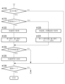
- the wearable device 2 executes the process shown in Figures 11 and 12 based on the observation support program 68.
- the wearable device 2 When the wearable device 2 receives a connection command (Yes in #201 in FIG. 11), it starts processing to establish a connection with the relay device 3 (#202), turns off the blue light-emitting element 6511 and the orange light-emitting element 6513, and blinks the green light-emitting element 6512 in 1/2 second cycles (#203). Then, once the connection is established (Yes in #204), it turns off the blue light-emitting element 6511 and the orange light-emitting element 6513, and blinks the green light-emitting element 6512 in 1/4 second cycles (#205).
- the wearable device 2 starts recording the heart sounds of the subject 10, measuring the temperature at three points on the subject 10's wrist, and measuring the ambient temperature (#207), and turns off the orange light-emitting element 6513, keeps the green light-emitting element 6512 blinking in 1/4 second cycles, and blinks the blue light-emitting element 6511 in 1/2 second cycles (#208).
- the wearable device 2 stops recording, starts transmitting the heart sound data recorded at the predetermined time to the relay device 3 as an audio file 80, starts transmitting data indicating each measured temperature to the relay device 3 as temperature data 81 (#210), and turns off the orange light-emitting element 6513 and the blue light-emitting element 6511 while keeping the green light-emitting element 6512 blinking at a 1/4 second cycle (#211).
- a predetermined time e.g. 15 seconds
- the wearable device 2 disconnects the connection (Yes in #212), it turns off all of the blue light-emitting element 6511, the green light-emitting element 6512, and the orange light-emitting element 6513 (#217).
- the wearable device 2 while the wearable device 2 is connected to a USB cable to charge the secondary battery 67 (Yes in #213), it constantly checks the charging status (#214). If charging is not complete (No in #215), it forcibly turns off the blue light-emitting element 6511 and the orange light-emitting element 6513, and leaves the green light-emitting element 6512 on (#216). Once charging is complete (Yes in #215), it forcibly turns off all three light-emitting elements (#217).
- the wearable device 2 acquires acceleration, etc., as follows.
- the wearable device 2 measures the acceleration in each of the X, Y, and Z directions, and also measures the temperature at each of the three points on the subject 10's wrist (#220). During measurement, as a general rule, the blue light emitter 6511 is blinked at 1/4 second intervals, and the green light emitter 6512 and orange light emitter 6513 are turned off (#221).
- the wearable device 2 measures the acceleration in each of the X-direction, Y-direction, and Z-direction (#222). Temperature is not measured. During measurement, as a rule, all three light emitters are turned off (#223).
- the wearable device 2 transmits data indicating the acceleration or temperature acquired in step #220 or #222 to the relay device 3 as acceleration data 82 or active temperature data 83 (#225). If a connection with the relay device 3 has not been established, it will be established. During establishment, the green light emitter 6512 may be caused to flash at 1/2 second intervals, and during transmission, the green light emitter 6512 may be caused to flash at 1/4 second intervals.
- a predetermined time e.g. 1 hour
- the wearable device 2 executes steps #201 to #225 as appropriate until the power is turned off.
- the subject's cardiac condition can be monitored less invasively and at lower cost than in the past. This allows medical personnel to intervene early before the symptoms of the subject's 10 heart failure worsen, reducing re-admissions that involve expensive medical expenses more than in the past.
- the skin surface temperature Ts is calculated after excluding abnormal values, the peripheral cold sensation can be obtained more accurately than in the past.
- the subject 10 can obtain heart sounds more easily than before. That is, by wearing the wearable device 2 so that the device main body 20 is on the palm side of the subject's left hand, for example, when the left arm is bent and the left palm is pressed against the center of the anterior chest, the microphone 621 is pressed against the optimal position directly above or near the heart of the subject 10. Therefore, more accurate heart sounds can be obtained with high sensitivity and low noise.
- the position of the device main body 20 relative to the left hand is constant, so by remembering the position when the left arm is bent and the left palm is pressed against the chest, the microphone can always be pressed against the correct position to obtain heart sounds in the same condition, and heart sounds can be analyzed under the same conditions, improving the accuracy of detection of heart failure.
- heart sounds can be obtained by a simple operation of pressing the start key 654 with the left arm bent and the left palm pressed against the chest, so that heart sounds can be obtained reliably without the hassle of obtaining regular heart sounds every day.
- the operation unit i.e., user interface unit 65, which is used by the subject 10 to operate to obtain heart sounds
- the operation unit i.e., user interface unit 65, which is used by the subject 10 to operate to obtain heart sounds
- the user interface unit 65 is located on the side surface 204 of the device body 20, aligned with the longitudinal direction of the subject 10's arm when worn on the wrist. Therefore, when the subject 10 bends his/her left arm and presses the microphone against his/her chest, the user interface unit 65 is on top and easily visible to the subject 10, making it extremely easy to operate the user interface unit 65 to obtain heart sounds.
- the patient can maintain the posture required for acquiring heart sounds with peace of mind, and there is less risk of the microphone slipping or becoming separated from the chest due to the arm being moved while acquiring heart sounds.
- the microphone is placed near the optimal position for detecting the third sound, which is useful for detecting heart failure, so the patient can easily acquire and record heart sounds at home by himself with high reproducibility.
- Fig. 13 is a diagram showing a first modified example of the wearable device 2.
- Fig. 14 is a diagram showing a second modified example of the wearable device 2.
- Fig. 15 is a diagram showing a modified example of the arrangement of three contacts.
- the subject 10 moves the entire wearable device 2 when recording heart sounds, but the wearable device 2 may be configured so that only the device body 20 can be moved, for example as shown in FIG. 14.
- the wearable device 2A shown in FIG. 14 is a first modified example of the wearable device 2, in which the protrusion 21A1 of the device body 20A fits into and engages with the groove 28A1 provided on the outer circumference of the wristband 28A, and the device body 20A can slide around the top or bottom of the wrist along the outer circumference of the wristband 28A and rotate about 180 degrees.
- Wristband 28A is attached to the wrist by a known fastener such as that shown in FIG. 2 or not shown. Wristband 28A does not rotate with respect to the wrist by itself.
- the groove 28A1 is located in the longitudinal center of the wristband 28A and extends for approximately half the circumference of the wrist, with cutouts 28A2 at both ends, each cut out over a length of approximately 1 to 2 centimeters at the bottom of the groove 28A1.
- first contact 6421, second contact 6422, and third contact 6423 are arranged on protrusion 21A1, biased outward by a spring or the like with good thermal conductivity.
- protrusion 21A1 slides inside groove 28A1, the tips of the three contacts are in a retracted state against the bottom of groove 28A1, but when protrusion 21A1 is positioned at the end of groove 28A1, the three contacts come into direct contact with the skin surface of the wrist via cutout 28A2.
- the wearable device 2 may be configured as shown in FIG. 14.
- the wearable device 2B shown in FIG. 14 is a second modified example of the wearable device 2, in which both ends of the wristband 28B are connected not to the ends of the device body 20B but at positions 602a and 602b that sandwich the three central contacts (first contact 6421, second contact 6422, and third contact 6423).
- the distance between both ends of the wristband 28B is short, so that the flexible wristband 28B can be easily rotated around the wrist without being hindered by the overall length of the device body 20B.
- the activity level of the subject 10 is calculated by the heart failure detection server 40, but it may be calculated by the wearable device 2 or the relay device 3. Also, the process of detecting heart failure is performed by the heart failure detection server 40, but it may be performed by the wearable device 2 or the relay device 3.
- the skin surface temperature Ts is calculated by the wearable device 2, but it may also be calculated by the relay device 3 or the heart failure detection server 40.
- the wearable device 2 may be equipped with the functions of a smart watch, for example, as follows: Transparent rubber such as highly transparent silicone rubber is used as the rubber 623 (see FIG. 5), and a transparent piezoelectric film is used as the microphone 621. An organic EL display is then placed on the back side of the microphone 621. The organic EL display is controlled by the CPU 611, and displays the date, time, state of the wearable device 2, and the ambient temperature Te, as well as the heart failure detection results, activity level, and skin surface temperature Ts of the subject 10, as necessary. Furthermore, a touch panel may be provided between the microphone 621 and the organic EL display.
- Transparent rubber such as highly transparent silicone rubber is used as the rubber 623 (see FIG. 5)
- a transparent piezoelectric film is used as the microphone 621.
- An organic EL display is then placed on the back side of the microphone 621.
- the organic EL display is controlled by the CPU 611, and displays the date, time, state of the wearable device 2, and the ambient temperature
- the state of the wearable device 2 is notified to the subject 10 by illuminating the three light-emitting elements, but it may also be notified by outputting sound from the speaker 63.
- the time at which the heart sounds should be acquired may be set using a clock function, and an alarm sound may be output from the speaker 63 each time this time arrives. This allows the heart sounds to be acquired at the correct time, and prevents forgetting to acquire the heart sounds.
- the three contacts are arranged on a straight line, but they may also be arranged on a curve that corresponds to the circumference of the wrist.
- the three contacts are arranged on a straight line perpendicular to the longitudinal direction of the arm, but this is not limited as long as the distance between any two contacts in the width direction of the wrist is a predetermined distance or more. If this condition is met, for example, the three contacts may be arranged so that their positions in the longitudinal direction of the arm are different from each other, as shown in FIG. 15.
- the predetermined range of distance is set based on the route of the radial cutaneous vein near the wrist. Specifically, it is set so that when any one of the three contacts is positioned directly above the radial cutaneous vein, the other two contacts are positioned at a predetermined distance or more from directly above the radial cutaneous vein.
- the number of contacts is not limited to three. For example, it may be two, or four or more.
- the wearable device 2 compares any two measured values, and if the difference between the two is equal to or greater than a predetermined temperature, it detects the higher measured value as an abnormal value. It then calculates the average or median of the measured values other than the abnormal values as the skin surface temperature Ts.
- FIG. 16 is a diagram showing an example of the appearance of each of wearable devices 2C and 2D.
- FIG. 17 is a diagram showing an example of the appearance of each of the upper and lower sides of device main body 20E.
- FIG. 18 is a diagram showing an example of the appearance of each of the side and lower sides of wearable device 2F.
- FIG. 19 is a front view and an oblique view of connecting member 26F.
- FIG. 20 is a diagram showing an example of female part 26Fb and male part 26Fd.
- FIG. 21 is a diagram showing an example of the appearance of each of the upper and lower sides of wearable device 2G.
- a single circular piezoelectric element with a diameter of about 20 mm is used as the microphone 621, but one or more microphones using MEMS (Micro Electro Mechanical Systems) measuring a few millimeters by a few millimeters (hereinafter referred to as "MEMS microphones”) may also be used.
- MEMS microphone is a small microphone assembled and packaged with a MEMS chip that converts audio to electrical signals and an IC chip that processes signals.
- the IC chip may have a filter function that passes or blocks specific frequencies, a noise removal function, an automatic level adjustment function, and the like.
- a condenser microphone (ECM) may also be used as the microphone 621.
- a display may be provided on the top surface of the wearable device 2.
- an organic EL display may be placed in the center of the top surface 201 of the device body 20C as the display 2C1, and eight MEMS microphones may be placed around it as the microphones 621.
- a thin rubber film such as silicone may be attached to the surface of the microphone 621 to make it dust-proof or water-proof.
- noise cancellation may be performed on the voice collected by the multiple microphones 621.
- noise components may be removed and the waveform of the heart sounds may be smoothed by comparing or complementing the phase of the audio signals from each microphone 621. This allows good heart sounds to be recorded with reduced ambient noise.
- a first contact 6421, a second contact 6422, and a third contact 6423 are arranged on the underside (rear surface) 202 to measure the skin temperature, similar to the device main body 20 (see FIG. 6).
- MEMS microphones may be arranged as microphones 621 on the top surface 201 of the device body 20D, and a display 2D1 may also be arranged.
- a thick, disk-shaped housing may be used as the housing of the device body 20E, an organic EL display with a circular display surface may be arranged as the display 2E1, and multiple (e.g., three) MEMS microphones may be arranged around it as microphones 621.
- multiple (e.g., six) MEMS microphones may be arranged as microphones 621 on the underside 202 along with the first contact 6421, second contact 6422, and third contact 6423 of the skin temperature measurement unit, and an organic EL display may be arranged as display 2F1 on the upper side 201.
- the wearable device 2F may be configured so that the device body 20F can rotate around the longitudinal direction of the elastic wristband 28F as the axis of rotation so that the device does not need to be removed from the arm when recording heart sounds.
- the wearable device 2F may be configured as follows.
- Cylindrical holes 204a, 205a are provided on two side surfaces 204, 205 of the device body 20F that are perpendicular to the longitudinal direction of the wristband 28F, i.e., the circumferential direction of the wrist. Furthermore, disk-shaped spaces 204b, 205b with larger diameters are provided concentrically at the ends of the holes 204a, 205a.
- the wearable device 2F has two metal connecting members 27F1, 27F2.
- the connecting member 27F1 is an integral structure of a base portion 27Fa, an axis portion 27Fb, and a mooring portion 27Fc.
- the base portion 27Fa is fixed to one end portion 28Fa of the wristband 28F.
- the axis portion 27Fb passes through a hole 204a, and the mooring portion 27Fc is rotatably arranged in the space 204b, and serves as a retainer to prevent the axis portion 27Fb from slipping out of the hole 204a.
- a mooring portion 27Fc can be implemented, for example, by a pin biased radially outwardly of the axis portion 27Fb by a spring.
- the space 204b can be made part of the internal space of the housing of the device main body 20F, and the mooring portion 27Fc can be integrated with the axis portion 27Fb by screws or welding when assembling the device main body 20F.
- the diameter of shaft 27Fb is slightly smaller than the diameter of hole 204a, with a clearance of about 0.1 millimeters between them.
- the maximum length between both end faces of anchoring portion 27Fc is greater than the diameter of hole 204a, so that anchoring portion 27Fc abuts against the wall of space 204b to prevent it from coming loose.
- the overall length of anchoring portion 27Fc can be made greater than the diameter of hole 204a by, for example, about 3 millimeters.
- the connecting member 27F1 connects the side surface 204 of the device body 20F and the end 28Fa of the wristband 28F so that the device body 20F and the wristband 28F rotate relatively around the shaft portion 27Fb as the axis of rotation.
- the connecting member 27F2 also connects the side surface 205 of the device body 20F and the other end 28Fb of the wristband 28F, similar to the connecting member 27F1.
- the subject 10 wears the wearable device 2F so that the underside 202 of the device body 20F is in contact with the subject's 10 arm.
- the subject moves the device body 20F toward the palm of the hand as appropriate, and then rotates the device body 20F 180 degrees so that the underside 202 appears. The subject then places the underside 202 near his or her own heart to record heart sounds.
- the wearable device 2 when the heart sounds are not being recorded, it is possible to measure not only the skin temperature of the subject 10 but also information related to the pulse (e.g., pulse wave, pulse rate). In other words, it is possible to obtain information related to the pulse at all times. Furthermore, when recording the heart sounds, it is possible to measure the temperature near the heart, i.e., the core temperature or central temperature. By using this information, it is possible to more accurately diagnose heart failure or detect its signs.
- information related to the pulse e.g., pulse wave, pulse rate
- a connecting member 26F as shown in Figures 19(A) and (B) may be used.
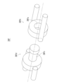
- the connecting member 26F is a metal part that is often used in products such as key holders, and is composed of a female part 26Fb having a cylindrical hole 26Fa and a male part 26Fd having a headed cylindrical pin 26Fc as shown in Figure 20.
- the cylindrical part of the pin 26Fc passes through the hole 26Fa, and the female part 26Fb and the male part 26Fd can rotate relatively with the pin 26Fc as the rotation axis.
- One end of the female part 26Fb and the male part 26Fd is fixed to the device main body 20F, and the other end is fixed to the wristband 28F. This allows the device main body 20F to rotate with respect to the wristband 28F.
- the user interface unit 65 (see FIG. 2) is omitted from FIG. 18, it is preferable to place the user interface unit 65 on the side surface 204 of the device body 20F, so as to avoid the connection portion with the connecting member 27F or 27F, i.e., the rotation axis, and between the connecting member 27F (or the connecting member 26F) and the top surface 201.
- the user interface unit 65 may be placed on another side surface, such as the sides 203 and 205 (see FIG. 6).
- the user interface unit 65 may be provided on the surface of the wristband 28F near the end that is connected to the side surface 204.
- a thick, disk-shaped housing may be used, as in the wearable device 2G shown in FIG. 20, with a circular organic EL display placed as the display 2G1 and multiple (e.g., three) MEMS microphones placed around it as the microphones 621.
- the configuration of the whole or each part of the heart failure detection system 1, the wearable devices 2, and 2B to 2G, the content of the processing, the order of the processing, etc. may be modified as appropriate in accordance with the spirit of the present invention.
- Heart failure detection system 10 Subject 40 Heart failure detection server (heart failure detection device) 2, 2B to 2G: wearable device 20, 20B to 20G: device main body (main body) 201 Top surface 202 Bottom surface 204 Side surface (operation surface) 28, 28F Wristband 611 CPU (calculation means) 614 3-axis acceleration sensor 62 Sound collection unit 621 Microphone 623 Rubber 65 User interface unit (operation unit) 6511 Blue light emitter (display means) 6512 Green light emitter (display means) 6513 Orange light emitter (display means) 6421 First Contact (Contact) 6422 Second Contact (Contact) 6423 Third Contact (Contact) 654 Start key (key) 66 Ambient temperature measuring unit (ambient temperature measuring means) 73 Skin temperature acquisition module (calculation means)
Landscapes
- Health & Medical Sciences (AREA)
- Life Sciences & Earth Sciences (AREA)
- Physics & Mathematics (AREA)
- Surgery (AREA)
- General Health & Medical Sciences (AREA)
- Engineering & Computer Science (AREA)
- Biomedical Technology (AREA)
- Heart & Thoracic Surgery (AREA)
- Medical Informatics (AREA)
- Molecular Biology (AREA)
- Veterinary Medicine (AREA)
- Animal Behavior & Ethology (AREA)
- Public Health (AREA)
- Pathology (AREA)
- Biophysics (AREA)
- Physiology (AREA)
- Cardiology (AREA)
- Acoustics & Sound (AREA)
- Dentistry (AREA)
- Oral & Maxillofacial Surgery (AREA)
- Pulmonology (AREA)
- Measuring And Recording Apparatus For Diagnosis (AREA)
- Measuring Pulse, Heart Rate, Blood Pressure Or Blood Flow (AREA)
Priority Applications (4)
| Application Number | Priority Date | Filing Date | Title |
|---|---|---|---|
| JP2025510923A JPWO2024204193A1 (https=) | 2023-03-28 | 2024-03-26 | |
| EP24780303.4A EP4699524A1 (en) | 2023-03-28 | 2024-03-26 | Wearable device and heart failure detection system |
| CN202480022131.1A CN121001651A (zh) | 2023-03-28 | 2024-03-26 | 可穿戴装置及心力衰竭检出系统 |
| US19/342,559 US20260026774A1 (en) | 2023-03-28 | 2025-09-27 | Wearable device and heart failure detection system |
Applications Claiming Priority (2)
| Application Number | Priority Date | Filing Date | Title |
|---|---|---|---|
| JP2023051480 | 2023-03-28 | ||
| JP2023-051480 | 2023-03-28 |
Related Child Applications (1)
| Application Number | Title | Priority Date | Filing Date |
|---|---|---|---|
| US19/342,559 Continuation US20260026774A1 (en) | 2023-03-28 | 2025-09-27 | Wearable device and heart failure detection system |
Publications (1)
| Publication Number | Publication Date |
|---|---|
| WO2024204193A1 true WO2024204193A1 (ja) | 2024-10-03 |
Family
ID=92906659
Family Applications (1)
| Application Number | Title | Priority Date | Filing Date |
|---|---|---|---|
| PCT/JP2024/011938 Ceased WO2024204193A1 (ja) | 2023-03-28 | 2024-03-26 | ウェアラブル装置および心不全検出システム |
Country Status (5)
| Country | Link |
|---|---|
| US (1) | US20260026774A1 (https=) |
| EP (1) | EP4699524A1 (https=) |
| JP (1) | JPWO2024204193A1 (https=) |
| CN (1) | CN121001651A (https=) |
| WO (1) | WO2024204193A1 (https=) |
Citations (10)
| Publication number | Priority date | Publication date | Assignee | Title |
|---|---|---|---|---|
| JPS625012U (https=) * | 1985-06-25 | 1987-01-13 | ||
| JPH0529686A (ja) | 1991-07-19 | 1993-02-05 | Hitachi Ltd | 光増幅装置 |
| JPH074232A (ja) | 1993-03-08 | 1995-01-10 | Tadayoshi Natsubori | 排気管を必要とするエンジンのための二次燃焼室装置 |
| JP2001149329A (ja) * | 1999-11-25 | 2001-06-05 | Matsushita Electric Works Ltd | 体脂肪測定方法及びその装置 |
| JP2007195693A (ja) * | 2006-01-25 | 2007-08-09 | Matsushita Electric Works Ltd | 携帯型心電計測装置 |
| JP2017029459A (ja) * | 2015-08-03 | 2017-02-09 | Kddi株式会社 | 脈拍測定装置及び脈拍測定方法 |
| JP2018525071A (ja) * | 2015-07-01 | 2018-09-06 | カリフォルニア インスティチュート オブ テクノロジー | 心音及び脈波形の取得及び解析 |
| JP2020039472A (ja) | 2018-09-07 | 2020-03-19 | 国立大学法人大阪大学 | 心不全の検出方法および装置、検出端末装置、心不全検出支援システム、その生産方法、並びにコンピュータプログラム |
| JP2021501029A (ja) | 2017-10-27 | 2021-01-14 | シンプル ヘルス ラブス インコーポレイテッド | ハンドヘルド心臓モニタリングデバイス |
| JP2022027219A (ja) * | 2020-07-31 | 2022-02-10 | 太陽誘電株式会社 | 生体情報測定装置及び生体情報の測定方法 |
-
2024
- 2024-03-26 CN CN202480022131.1A patent/CN121001651A/zh active Pending
- 2024-03-26 WO PCT/JP2024/011938 patent/WO2024204193A1/ja not_active Ceased
- 2024-03-26 JP JP2025510923A patent/JPWO2024204193A1/ja active Pending
- 2024-03-26 EP EP24780303.4A patent/EP4699524A1/en active Pending
-
2025
- 2025-09-27 US US19/342,559 patent/US20260026774A1/en active Pending
Patent Citations (10)
| Publication number | Priority date | Publication date | Assignee | Title |
|---|---|---|---|---|
| JPS625012U (https=) * | 1985-06-25 | 1987-01-13 | ||
| JPH0529686A (ja) | 1991-07-19 | 1993-02-05 | Hitachi Ltd | 光増幅装置 |
| JPH074232A (ja) | 1993-03-08 | 1995-01-10 | Tadayoshi Natsubori | 排気管を必要とするエンジンのための二次燃焼室装置 |
| JP2001149329A (ja) * | 1999-11-25 | 2001-06-05 | Matsushita Electric Works Ltd | 体脂肪測定方法及びその装置 |
| JP2007195693A (ja) * | 2006-01-25 | 2007-08-09 | Matsushita Electric Works Ltd | 携帯型心電計測装置 |
| JP2018525071A (ja) * | 2015-07-01 | 2018-09-06 | カリフォルニア インスティチュート オブ テクノロジー | 心音及び脈波形の取得及び解析 |
| JP2017029459A (ja) * | 2015-08-03 | 2017-02-09 | Kddi株式会社 | 脈拍測定装置及び脈拍測定方法 |
| JP2021501029A (ja) | 2017-10-27 | 2021-01-14 | シンプル ヘルス ラブス インコーポレイテッド | ハンドヘルド心臓モニタリングデバイス |
| JP2020039472A (ja) | 2018-09-07 | 2020-03-19 | 国立大学法人大阪大学 | 心不全の検出方法および装置、検出端末装置、心不全検出支援システム、その生産方法、並びにコンピュータプログラム |
| JP2022027219A (ja) * | 2020-07-31 | 2022-02-10 | 太陽誘電株式会社 | 生体情報測定装置及び生体情報の測定方法 |
Non-Patent Citations (1)
| Title |
|---|
| See also references of EP4699524A1 |
Also Published As
| Publication number | Publication date |
|---|---|
| CN121001651A (zh) | 2025-11-21 |
| US20260026774A1 (en) | 2026-01-29 |
| JPWO2024204193A1 (https=) | 2024-10-03 |
| EP4699524A1 (en) | 2026-02-25 |
Similar Documents
| Publication | Publication Date | Title |
|---|---|---|
| EP3565460B1 (en) | System and method for providing user feedback of blood pressure sensor placement and contact quality | |
| US7894888B2 (en) | Device and method for measuring three-lead ECG in a wristwatch | |
| EP3566036B1 (en) | Blood pressure measurement system using force resistive sensor array | |
| US7963923B2 (en) | Blood pressure meter | |
| US20170319082A1 (en) | Phono-Electro-Cardiogram Monitoring Unit | |
| JP6281290B2 (ja) | リストバンド型腕動作判定装置 | |
| US20110015496A1 (en) | Portable medical device | |
| CN106456008A (zh) | 利用移动设备和配件进行心脏监测的方法和系统 | |
| JPWO2004089202A1 (ja) | 生体情報監視システム | |
| CN210612114U (zh) | 震动感测装置、血压测量装置、及心肺效能监控装置 | |
| JP6800759B2 (ja) | ユーザ端末 | |
| WO2015158220A1 (zh) | 颈戴式心电检测装置 | |
| JP3569247B2 (ja) | 生体情報計測装置および健康管理システム | |
| US20240123180A1 (en) | Wristwatch System for Detecting Negative Emotional State of a Wearer | |
| JP7484250B2 (ja) | 携帯型心電装置及び心電測定システム | |
| WO2024204193A1 (ja) | ウェアラブル装置および心不全検出システム | |
| WO2024093827A1 (zh) | 手表设备、生理音测量的方法、装置以及计算机存储介质 | |
| KR101849857B1 (ko) | 웨어러블 생체 진단 장치 | |
| US20240081660A1 (en) | Sensorized earphone device for out-of-ear measurements | |
| WO2026041962A1 (en) | Continuous tremor monitoring system and method | |
| JP2024031078A (ja) | 生体情報測定装置 | |
| KR20250039979A (ko) | 생성된 캐비티 바이오메트릭 센서 | |
| JP2023061879A (ja) | 生体情報計測装置および生体情報モニタリングシステム | |
| JP2006305187A (ja) | 耳式血圧計及びその収納ケース |
Legal Events
| Date | Code | Title | Description |
|---|---|---|---|
| 121 | Ep: the epo has been informed by wipo that ep was designated in this application |
Ref document number: 24780303 Country of ref document: EP Kind code of ref document: A1 |
|
| DPE2 | Request for preliminary examination filed before expiration of 19th month from priority date (pct application filed from 20040101) | ||
| ENP | Entry into the national phase |
Ref document number: 2025510923 Country of ref document: JP Kind code of ref document: A |
|
| WWE | Wipo information: entry into national phase |
Ref document number: 2025510923 Country of ref document: JP |
|
| WWE | Wipo information: entry into national phase |
Ref document number: 2024780303 Country of ref document: EP |
|
| NENP | Non-entry into the national phase |
Ref country code: DE |
|
| ENP | Entry into the national phase |
Ref document number: 2024780303 Country of ref document: EP Effective date: 20251028 |
|
| ENP | Entry into the national phase |
Ref document number: 2024780303 Country of ref document: EP Effective date: 20251028 |
|
| ENP | Entry into the national phase |
Ref document number: 2024780303 Country of ref document: EP Effective date: 20251028 |
|
| ENP | Entry into the national phase |
Ref document number: 2024780303 Country of ref document: EP Effective date: 20251028 |
|
| ENP | Entry into the national phase |
Ref document number: 2024780303 Country of ref document: EP Effective date: 20251028 |
|
| ENP | Entry into the national phase |
Ref document number: 2024780303 Country of ref document: EP Effective date: 20251028 |
|
| ENP | Entry into the national phase |
Ref document number: 2024780303 Country of ref document: EP Effective date: 20251028 |
|
| ENP | Entry into the national phase |
Ref document number: 2024780303 Country of ref document: EP Effective date: 20251028 |
|
| ENP | Entry into the national phase |
Ref document number: 2024780303 Country of ref document: EP Effective date: 20251028 |
|
| ENP | Entry into the national phase |
Ref document number: 2024780303 Country of ref document: EP Effective date: 20251028 |
|
| WWP | Wipo information: published in national office |
Ref document number: 2024780303 Country of ref document: EP |