WO2024204087A1 - ステータ、モータ、及びステータの製造方法 - Google Patents
ステータ、モータ、及びステータの製造方法 Download PDFInfo
- Publication number
- WO2024204087A1 WO2024204087A1 PCT/JP2024/011745 JP2024011745W WO2024204087A1 WO 2024204087 A1 WO2024204087 A1 WO 2024204087A1 JP 2024011745 W JP2024011745 W JP 2024011745W WO 2024204087 A1 WO2024204087 A1 WO 2024204087A1
- Authority
- WO
- WIPO (PCT)
- Prior art keywords
- stator
- axial direction
- covering member
- hole
- circuit board
- Prior art date
- Legal status (The legal status is an assumption and is not a legal conclusion. Google has not performed a legal analysis and makes no representation as to the accuracy of the status listed.)
- Ceased
Links
Images




Classifications
-
- H—ELECTRICITY
- H02—GENERATION; CONVERSION OR DISTRIBUTION OF ELECTRIC POWER
- H02K—DYNAMO-ELECTRIC MACHINES
- H02K15/00—Processes or apparatus specially adapted for manufacturing, assembling, maintaining or repairing of dynamo-electric machines
- H02K15/02—Processes or apparatus specially adapted for manufacturing, assembling, maintaining or repairing of dynamo-electric machines of stator or rotor bodies
- H02K15/021—Magnetic cores
- H02K15/026—Wound cores
-
- H—ELECTRICITY
- H02—GENERATION; CONVERSION OR DISTRIBUTION OF ELECTRIC POWER
- H02K—DYNAMO-ELECTRIC MACHINES
- H02K1/00—Details of the magnetic circuit
- H02K1/06—Details of the magnetic circuit characterised by the shape, form or construction
- H02K1/12—Stationary parts of the magnetic circuit
- H02K1/16—Stator cores with slots for windings
-
- H—ELECTRICITY
- H02—GENERATION; CONVERSION OR DISTRIBUTION OF ELECTRIC POWER
- H02K—DYNAMO-ELECTRIC MACHINES
- H02K15/00—Processes or apparatus specially adapted for manufacturing, assembling, maintaining or repairing of dynamo-electric machines
- H02K15/12—Impregnating, moulding insulation, heating or drying of windings, stators, rotors or machines
-
- H—ELECTRICITY
- H02—GENERATION; CONVERSION OR DISTRIBUTION OF ELECTRIC POWER
- H02K—DYNAMO-ELECTRIC MACHINES
- H02K15/00—Processes or apparatus specially adapted for manufacturing, assembling, maintaining or repairing of dynamo-electric machines
- H02K15/12—Impregnating, moulding insulation, heating or drying of windings, stators, rotors or machines
- H02K15/123—Impregnating, moulding insulation, heating or drying of windings, stators, rotors or machines of casings or enclosures
-
- H—ELECTRICITY
- H02—GENERATION; CONVERSION OR DISTRIBUTION OF ELECTRIC POWER
- H02K—DYNAMO-ELECTRIC MACHINES
- H02K3/00—Details of windings
- H02K3/32—Windings characterised by the shape, form or construction of the insulation
-
- H—ELECTRICITY
- H02—GENERATION; CONVERSION OR DISTRIBUTION OF ELECTRIC POWER
- H02K—DYNAMO-ELECTRIC MACHINES
- H02K3/00—Details of windings
- H02K3/32—Windings characterised by the shape, form or construction of the insulation
- H02K3/34—Windings characterised by the shape, form or construction of the insulation between conductors or between conductor and core, e.g. slot insulation
- H02K3/345—Windings characterised by the shape, form or construction of the insulation between conductors or between conductor and core, e.g. slot insulation between conductor and core, e.g. slot insulation
-
- H—ELECTRICITY
- H02—GENERATION; CONVERSION OR DISTRIBUTION OF ELECTRIC POWER
- H02K—DYNAMO-ELECTRIC MACHINES
- H02K3/00—Details of windings
- H02K3/44—Protection against moisture or chemical attack; Windings specially adapted for operation in liquid or gas
-
- H—ELECTRICITY
- H02—GENERATION; CONVERSION OR DISTRIBUTION OF ELECTRIC POWER
- H02K—DYNAMO-ELECTRIC MACHINES
- H02K3/00—Details of windings
- H02K3/46—Fastening of windings on the stator or rotor structure
- H02K3/52—Fastening salient pole windings or connections thereto
- H02K3/521—Fastening salient pole windings or connections thereto applicable to stators only
- H02K3/522—Fastening salient pole windings or connections thereto applicable to stators only for generally annular cores with salient poles
-
- H—ELECTRICITY
- H02—GENERATION; CONVERSION OR DISTRIBUTION OF ELECTRIC POWER
- H02K—DYNAMO-ELECTRIC MACHINES
- H02K5/00—Casings; Enclosures; Supports
- H02K5/04—Casings or enclosures characterised by the shape, form or construction thereof
- H02K5/22—Auxiliary parts of casings not covered by groups H02K5/06-H02K5/20, e.g. shaped to form connection boxes or terminal boxes
- H02K5/225—Terminal boxes or connection arrangements
-
- H—ELECTRICITY
- H02—GENERATION; CONVERSION OR DISTRIBUTION OF ELECTRIC POWER
- H02K—DYNAMO-ELECTRIC MACHINES
- H02K2203/00—Specific aspects not provided for in the other groups of this subclass relating to the windings
- H02K2203/03—Machines characterised by the wiring boards, i.e. printed circuit boards or similar structures for connecting the winding terminations
Definitions
- the present invention relates to a stator, a motor, and a method for manufacturing a stator.
- stator assembly is placed in a storage space in a cover.
- a circuit board is loosely inserted into the opening in the cover.
- a filler is filled between the storage space in the cover and the stator assembly through the gap between the cover and the circuit board, and is solidified (see, for example, JP 2007-159393 A).
- the purpose of the present invention is to improve the electrical insulation of the stator surface.
- the stator of the first illustrative example of the present invention comprises an annular stator core surrounding a central axis extending in the axial direction, a plurality of coil portions, a circuit board, and an electrically insulating covering member.
- the stator core has slots. The slots penetrate in the axial direction and are arranged in a circumferential direction. The coil portions are respectively disposed in the slots.
- the circuit board is disposed on one side of the stator core in the axial direction and is electrically connected to a lead wire drawn from the coil portion.
- the covering member covers at least the coil portion.
- the circuit board has a first through hole extending in the axial direction. At least a portion of the first through hole overlaps with the stator core when viewed from the axial direction.
- a stator includes a stator core, a plurality of coil portions, an electrically insulating covering member, and a cover member.
- the stator core has a plurality of slots arranged in the circumferential direction penetrating the axial direction, and is annular in shape surrounding a central axis extending in the axial direction.
- the plurality of coil portions are respectively arranged in the slots.
- the covering member covers at least the coil portions.
- the cover member houses a stator assembly including the stator core and the coil portions.
- the cover member is a covered cylinder that opens toward one side in the axial direction.
- a second through hole extending in the axial direction is arranged in a lid portion of the cover member. At least a portion of the second through hole overlaps with the stator core when viewed from the axial direction.
- An exemplary motor of the present invention includes a stator of the first or second example described above, and a rotor that can rotate around the central axis.
- An exemplary method for manufacturing a stator according to the present invention is the method for manufacturing the stator of the first example described above. This manufacturing method includes the steps of: positioning the circuit board so that at least a portion of the first through hole overlaps with the stator core when viewed from the axial direction; and positioning the covering member using the first through hole.
- an exemplary method for manufacturing a stator according to the present invention is the method for manufacturing the stator of the second example described above.
- the manufacturing method includes a step of arranging the cover member so that at least a portion of the second through hole overlaps with the stator core when viewed in the axial direction, and a step of arranging the covering member using the second through hole.
- the exemplary stator, motor, and stator manufacturing method of the present invention can improve the electrical insulation of the stator surface.
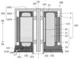
- FIG. 1 is a cross-sectional view of a motor according to an embodiment.
- FIG. 2 is a plan view of one axial side of the motor.
- FIG. 3 is a diagram showing an example of an assembly of the stator assembly.
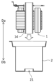
- FIG. 4 is a diagram showing an example of how the cover member is attached.
- FIG. 5A is a diagram showing an example of filling with a covering member before hardening.
- FIG. 5B is a diagram showing another example of filling with the covering material before hardening.
- FIG. 6 is a flow chart for explaining an example of a method for manufacturing a stator.
- FIG. 7 is a cross-sectional view of a motor according to a modified example of the embodiment.
- FIG. 8A is a diagram showing an example of filling with a coating member before hardening in a modified example.
- FIG. 8B is a diagram showing another example of filling with a covering material before hardening in the modified example.
- FIG. 9 is a flowchart for explaining an example of a method for manufacturing a stator in the modified example.
- the direction parallel to the central axis CA of the motor 100 is referred to as the "axial direction.”
- the direction from the stator core 11 to the circuit board 15, which will be described later, is referred to as the “one axial direction Da,” and the direction from the circuit board 15 to the stator core 11 is referred to as the “other axial direction Db.”
- the direction from the axial center of the component toward the axial end may be referred to as the “axial outward”
- the direction from the axial end of the component toward the axial center may be referred to as the "axial inward.”
- the direction perpendicular to the central axis CA is called the "radial direction,” and the direction of rotation about the central axis CA is called the “circumferential direction.”
- the direction approaching the central axis CA is called the “radial inward direction”
- the direction away from the central axis CA is called the “radial outward direction.”
- annular includes a shape that is continuous and uninterrupted throughout the entire circumferential area centered on the central axis CA, as well as a shape that has one or more interruptions in a portion of the entire area centered on the central axis CA. It also includes a shape that describes a closed curve on a curved surface that is centered on the central axis CA and intersects with the central axis CA.
- parallel includes not only a state in which the two do not intersect at all no matter how far they are extended, but also a state in which they are substantially parallel.
- perpendicular and orthogonal each include not only a state in which the two intersect at 90 degrees to each other, but also a state in which they are substantially perpendicular and a state in which they are substantially orthogonal, respectively.
- parallel and perpendicular each include a state in which there is an angle shift in the positional relationship between the two that does not deviate from the spirit of this invention.
- Embodiment Fig. 1 is a cross-sectional view of a motor 100 according to an embodiment.
- Fig. 2 is a plan view of one axial direction Da side of the motor 100.
- Fig. 1 shows the cross-sectional structure of the motor 100 taken along dashed line II in Fig. 2.
- a covering member 3 which will be described later, is shown with semi-transparent hatching.
- the motor 100 includes a shaft 101, a rotor 102, and a stator 103. As described below, the motor 100 can improve the filling efficiency of the electrically insulating coating member 3 that covers at least the coil portion 13, and can improve the electrical insulation of the surface of the stator 103 (particularly the coil portion 13).
- the shaft 101 extends axially along the central axis CA, and is rotatable around the central axis CA together with the rotor 102. That is, in this embodiment, the shaft 101 is a rotating shaft. However, this is not limiting, and the shaft 101 may be a fixed shaft fixed together with the stator 103, or may not be rotatable around the central axis CA. If it is a fixed shaft, a bearing is disposed between the shaft 101 and the rotor 102 to rotatably support the rotor 102 relative to the shaft 101.
- the rotor 102 is rotatable around the central axis CA.
- the rotor 102 is cylindrical with a lid, and in this embodiment, is fixed to the axial end of the shaft 101.
- the rotor 102 has a lid portion 1021, a tubular portion 1022, and a magnet 1023.
- the lid portion 1021 extends radially outward from the shaft 101.
- the tubular portion 1022 extends from the radial outer end of the lid portion 1021 in one axial direction Da and surrounds a part of the stator 103 (for example, the stator core 11, the coil portion 13, etc.).
- the magnet 1023 is disposed on the radial inner surface of the tubular portion 1022.
- the magnet 1023 different magnetic poles are arranged alternately in the circumferential direction.
- the magnet 1023 is directly fixed to the radial inner surface of the tubular portion 1022.
- the magnet 1023 may be fixed to the radially inner surface of the tube portion 1022 via a yoke made of a magnetic material that extends in the axial and circumferential directions.
- the stator 103 rotates the rotor 102 by a magnetic flux generated by energization. As shown in Fig. 1 and Fig. 2, the stator 103 includes a stator assembly 1, a cover member 2, and a covering member 3.
- the stator assembly 1 includes a stator core 11 , an insulator 12 , a plurality of coil portions 13 , a holding member 14 , and a circuit board 15 .
- the stator core 11 is annular and surrounds the central axis CA.
- the stator 103 has a stator core 11.
- the stator core 11 is a magnetic body, and in this embodiment is a laminated body in which plate-shaped electromagnetic steel sheets that extend in the radial direction are stacked in the axial direction.
- the stator core 11 is fixed to the radial outer surface of the retaining member 14, and faces the magnets 1023 in the radial direction.
- the stator core 11 also has slots 111.
- the slots 111 penetrate the stator core 11 in the axial direction and are arranged in multiple rows in the circumferential direction.
- the insulator 12 is electrically insulating and is arranged on the surface of the stator core 11 (particularly both axial end faces and the inner surface of the slot 111, etc.).
- the coil portions 13 are disposed in the respective slots 111.
- the stator 103 has a plurality of coil portions 13.
- each coil portion 13 is a component in which a conductor (reference number omitted) is disposed in a coil shape on the stator core 11 via an insulator 12.
- the conductor is, for example, an enamel-coated copper wire or a metal wire coated with an electrical insulating material, and is wound around the stator core 11 to form the coil portion 13.
- the plurality of coil portions 13 are arranged in the circumferential direction. When a drive current is supplied to each coil portion 13, the stator 103 is excited and drives the rotor 102.
- the retaining member 14 is cylindrical and extends in the axial direction around the central axis CA, and holds the stator core 11 on its radially outer surface.
- the stator 103 is equipped with the retaining member 14.
- the retaining member 14 also has a bearing 141 disposed on its inner circumferential surface, through which the shaft 101 is inserted. In this embodiment, the retaining member 14 rotatably supports the shaft 101 via the bearing 141.
- the bearing 141 may be a rolling bearing such as a ball bearing, or may be a sliding bearing.
- the circuit board 15 is disposed on one side of the axial direction Da relative to the stator core 11 and the coil portion 13, and is electrically connected to a lead wire 131 drawn from the coil portion 13.
- the stator 103 is equipped with a circuit board 15.
- the lead wire 131 is, for example, an end of a conductor that constitutes the coil portion 13.
- the circuit board 15 is mounted with a drive circuit for the stator 103, etc.
- the circuit board 15 is supported by a support member 121.
- the support member 121 extends in one axial direction Da from an insulator 12 disposed on one axial end face of the stator core 11.
- the circuit board 15 has a connector portion 151.
- the connector portion 151 is connected to at least one of the connection lines of the lead wire 131 and the external wiring 1510.
- the external wiring 1510 electrically connects the circuit board 15 to devices external to the motor 100.
- the external wiring 1510 is a connection line that is drawn from the circuit board 15 to the outside of the motor 100, and is connected to an external device, etc.
- the circuit board 15 further has a first through hole 152 extending in the axial direction. At least a portion of the first through hole 152 overlaps with the stator core 11 in the axial direction. In other words, at least a portion of the first through hole 152 overlaps with the stator core 11 when viewed in the axial direction.
- the first through hole 152 when viewed in the axial direction is rectangular in FIG. 2, but is not limited to this example and may not be rectangular.
- the first through hole 152 when viewed in the axial direction may be a polygonal shape other than a rectangle, or may be a circular shape including a perfect circle and an ellipse, or an arc shape.
- the first through hole 152 may also be a notch shape formed at the radial inner end or the radial outer end of the circuit board 15.
- the cross-sectional area of the first through hole 152 when viewed in the axial direction is 1 mm 2 or more.
- the aperture of the first through hole 152 is 1 mm or more.
- the first through-hole 152 can be used to densely arrange the covering member 3 in the space to be arranged, such as the surface of the coil portion 13.
- the covering member 3 before hardening has fluidity.
- the covering member 3 can be easily filled into the above-mentioned space with less gaps.
- air pushed out by the filling of the covering member 3 can be discharged to the outside of the stator 103 through the first through-hole 152.
- the covering member 3 can be placed in the above-mentioned space by hardening the covering member 3. Therefore, the filling efficiency of the covering member 3 before hardening can be improved, and the hardened covering member 3 can improve the electrical insulation of the surface of the stator 103 (particularly the coil portion 13). Furthermore, the dustproofness and waterproofness against the intrusion of liquids such as dust and water can be improved.
- At least a portion of the first through hole 152 overlaps with at least a portion of the slot 111 in the axial direction.
- at least a portion of the first through hole 152 overlaps with at least a portion of the slot 111 when viewed in the axial direction.
- this example does not exclude a configuration in which the first through hole 152 does not overlap at all with the slot 111 when viewed in the axial direction.
- the first through hole 152 is disposed at a position away from the connector portion 151.
- the minimum circumferential distance between the connector portion 151 and the first through hole 152 is 45° or more.
- the flow of the pre-hardened covering member 3 to be filled is less likely to be impeded by at least one of the above-mentioned connection lines (i.e., the lead wire 131, the external wiring 1510). Therefore, it is possible to suppress or prevent a decrease in the filling efficiency of the pre-hardened covering member 3, and the covering member 3 can be densely arranged even near the connector portion 151.
- this example does not exclude a configuration in which the first through hole 152 is disposed near the connector portion 151.
- the minimum circumferential distance between the connector portion 151 and the first through hole 152 may be less than 45°.
- the circuit board 15 further has a first recess 153 and a second recess 154.
- the first recess 153 is recessed radially inward at the radially outer end of the circuit board 15.
- the first recess 153 may be a single recess, or multiple recesses 153 may be arranged in the circumferential direction. In the latter case, the number of first recesses 153 is three in FIG. 2, but is not limited to this example and may be any number other than three.
- the second recess 154 is recessed radially outward at the radially inner end of the circuit board 15.
- the second recess 154 may be a single recess, or multiple recesses 154 may be arranged in the circumferential direction. In the latter case, the number of second recesses 154 is three in FIG. 2, but is not limited to this example and may be any number other than three.
- the shapes of the first recess 153 and the second recess 154 as viewed in the axial direction are each rectangular. However, this is not limited to the example, and the shape of at least one of the first recess 153 and the second recess 154 may be a polygonal shape other than a rectangle, or an arc shape including a semicircle.
- the first recess 153 or the second recess 154 may be omitted.
- the circuit board 15 has at least one of the first recess 153 and the second recess 154.
- the air between the stator assembly 1 and the cover member 2 can be further discharged through at least one of the recesses described above. This makes it easier to fill the gaps between the stator assembly 1 and the cover member 2 with the covering member 3, which means that the filling efficiency can be improved. This further improves the electrical insulation of the surface of the stator 103.
- the above examples do not exclude a configuration in which the circuit board 15 does not have both the first recess 153 and the second recess 154.
- At least one of the recesses described above overlaps at least a portion of the slot 111 in the axial direction.
- at least one of the first recess 153 and the second recess 154 overlaps at least a portion of the slot 111 when viewed from the axial direction.
- air pushed out of the slot 111 by filling the coating member 3 before hardening can be easily discharged to the outside of the stator 103 through at least one of the recesses described above. Therefore, it becomes easier to fill the coating member 3 into the slot 111 in which the coil portion 13 is arranged. Therefore, the surface of the coil portion 13 can be easily and without gaps covered with the coating member 3.
- this example does not exclude a configuration in which neither the first recess 153 nor the second recess 154 overlaps at least a portion of the slot 111 when viewed from the axial direction.
- the cover member 2 is in the shape of a covered cylinder that opens toward one axial direction Da.
- a central opening 21 through which the holding member 14 is inserted is disposed in the lid portion of the cover member 2.
- the stator 103 includes the cover member 2.
- the cover member 2 houses the stator assembly 1 that includes the stator core 11, the coil portion 13, the circuit board 15, etc.
- the covering member 3 covers the stator assembly 1. As described above, the stator 103 has the electrically insulating covering member 3. The covering member 3 covers at least the coil portion 13, and in this embodiment, covers the radially outer surface of the stator core 11, the insulator 12, the surface of at least the coil head 132 of the coil portion 13, the circuit board 15, etc.
- the coil head 132 refers to a portion of the coil portion 13 that protrudes axially outward beyond the stator core 11.
- the covering member 3 is disposed between the stator assembly 1 and the cover member 2. In this way, the surface of the stator assembly 1 can be covered with the cover member 2 and the covering member 3. This prevents dust and liquids such as water from entering the inside of the stator 103. This further improves the electrical insulation of the surface of the stator assembly 1.
- the covering member 3 covers a portion of the radially outer surface of the retaining member 14 (for example, a region axially outward from the stator core 11). That is, the stator assembly 1 covered with the covering member 3 includes the retaining member 14. In this way, the covering member 3 can be disposed between the retaining member 14 and the cover member 2.
- the surface of the stator assembly 1, including the outer surface of the retaining member 14, can be covered with the covering member 3 and the cover member 2, it is possible to prevent the intrusion of dust, water, and other liquids into the inside of the stator 103 from the outer surface of the retaining member 14 and the connection parts with other members (for example, the stator core 11), and the like, and the electrical insulation of the surface of the stator assembly 1 can be further improved.
- this example does not exclude a configuration in which the covering member 3 does not cover the retaining member 14.
- the covering member 3 further covers the surface of the circuit board 15 (and the circuits, devices, wiring, etc. mounted on the circuit board 15). In this way, the covering member 3 can prevent dust, water, and other liquids from adhering to the circuit board 15 (particularly the circuits, devices, wiring, etc. mounted on the circuit board 15). Therefore, the electrical insulation of the surface of the circuit board 15 can be improved.
- the covering member 3 is placed in the first through hole 152.
- the covering member 3 is also placed inside the first through hole 152 to block the first through hole 152.
- the covering member 3 covers one axial end of the first through hole 152. In this way, it is possible to prevent dust, water, and other liquids from entering the one axial direction Da side of the circuit board 15 through the first through hole 152.
- the above configuration does not exclude a configuration in which the covering member 3 does not cover the surface of the circuit board 15, and a configuration in which the covering member 3 is not disposed in the first through hole 152.
- FIG. 3 is a diagram showing an example of assembly of the stator assembly 1.
- Fig. 4 is a diagram showing an example of mounting the cover member 2.
- Fig. 5A is a diagram showing an example of filling with the covering member 3 before hardening.
- Fig. 5B is a diagram showing another example of filling with the covering member 3 before hardening.
- Fig. 6 is a flow chart for explaining an example of a manufacturing method of the stator 103. Note that in Figs.
- the orientations of the one axial direction Da and the other axial direction Db on the paper surface are shown opposite to those in Fig. 1. Also, in Figs. 5A and 5B, the covering member 3 is shown with semi-transparent hatching.
- the stator assembly 1 is assembled (step S11).
- the coil portion 13 is arranged in the stator core 11 (slot 111) by winding a conductor around the teeth (not shown) of the stator core 11 via the insulator 12.
- adhesive (not shown) is applied to the radially inner surface of the stator core 11, and a cylindrical retaining member 14 is inserted into the cylindrical radially inner end of the stator core 11. This fixes the stator core 11 to the radially outer surface of the retaining member 14.
- the lead wire 131 of the coil portion 13 and the external wiring 1510 are connected to the connector portion 151 of the circuit board 15, and the circuit board 15 is arranged on one axial side Da of the stator core 11.
- the circuit board 15 is supported by the support member 121.
- the one axial side Da of the retaining member 14 is inserted into the central opening 155 of the circuit board 15.
- the circuit board 15 is arranged so that at least a portion of the first through hole 152 overlaps with the stator core 11 (preferably at least a portion of any of the slots 111) when viewed from the axial direction. This arrangement improves the filling efficiency of the covering member 3 before hardening, and the hardened covering member 3 improves the electrical insulation of the surface of the stator 103.
- the stator assembly 1 is housed in the lidded cylindrical cover member 2 (step S12).
- the other axial side Db of the retaining member 14 is inserted into the central opening 21 of the lid portion of the cover member 2.
- the radial inner end of the lid portion contacts the radial outer surface of the retaining member 14 along the edge of the central opening 21.
- the covering member 3 is placed between the stator assembly 1 and the cover member 2 using the first through hole 152 of the circuit board 15 (step S13). This allows the covering member 3 to be easily filled into the space where it is to be placed, such as the surface of the coil portion 13 arranged on the stator core 11. At this time, air pushed out by the filling of the covering member 3 can also be discharged to the outside of the stator 103 through the first through hole 152. This improves the filling efficiency of the covering member 3 before it hardens, and the hardened covering member 3 can improve the electrical insulation of the surface of the stator 103 (particularly the coil portion 13).
- the unhardened coating member 3 is discharged from the tip (discharge port) of the nozzle 30, and the unhardened coating member 3 fills the gap space between the stator assembly 1 and the cover member 2.
- the nozzle 30 for injecting the fluid covering member 3 is inserted into the first through hole 152 from the one axial direction Da side of the circuit board 15, and the covering member 3 is injected.
- the nozzle 30 may be further inserted into the slot 111 to inject the covering member 3.
- the covering member 3 before hardening can be injected in a state where the injection port of the nozzle 30 inserted into the slot 111 from the one axial direction Da side is positioned closer to the other axial direction Db side of the slot 111.
- the covering member 3 before hardening can be filled more tightly in the space to be filled along the surface of the stator 103 (especially the part on the other axial direction Db side). Therefore, the filling efficiency of the covering member 3 before hardening can be further improved.
- this is not limited to this example, and the nozzle 30 does not have to be inserted into the slot 111.
- the nozzle 30 may move in the axial direction (particularly in one axial direction Da) while injecting the coating member 3.
- the nozzle 30 preferably moves in the one axial direction Da, and more preferably moves in the one axial direction Da in response to the rise (movement to one axial direction Da) of the upper surface (one axial end surface) of the coating member 3 injected from the nozzle 30.
- the injection port of the nozzle 30 may be lower (the other axial direction Db) than the upper surface (one axial end surface) of the coating member 3, or may be higher (one axial direction Da) than the upper surface (one axial end surface) of the coating member 3.
- the coating member 3 can be injected while changing the position of the injection port in the axial direction. Therefore, the injection process of the coating member 3 can be carried out in a manner more suitable for dense filling of the coating member 3.
- the nozzle 30 by moving the nozzle 30 so that the injection port is always above (on one axial Da side) the top surface of the coating member 3 (one axial end surface), it is possible to prevent the coating member 3 from adhering to the vicinity of the injection port of the nozzle 30. Therefore, it is possible to prevent the coating member 3 that has deteriorated over time due to being deposited around the injection port from being mixed into the newly injected coating member 3.
- the nozzle 30 since the nozzle 30 is not pulled out from the filled coating member 3, it is possible to prevent the generation of air bubbles that would otherwise occur when the nozzle 30 is pulled out.
- the fluid covering member 3 may be poured into the first through-hole 152 from one axial side Da of the circuit board 15.
- the nozzle 30 is placed on one axial side Da of the first through-hole 152 of the circuit board 15.
- the nozzle 30 may move in the axial direction while injecting the covering member 3.
- the covering member 3 can be easily positioned using the first through hole 152.
- the upper surface (i.e., one axial end surface) of the covering member 3 before hardening is preferably located in one axial direction Da from the circuit board 15 (and in the other axial direction Db from one axial end of the holding member 14).
- this example does not exclude a configuration in which the upper surface of the covering member 3 before hardening is not located in one axial direction Da from the circuit board 15.
- the axial position of the upper surface of the covering member 3 before hardening may be the same as the circuit board 15, or may be in the other axial direction Db from the circuit board 15. In the latter case, the axial position of the upper surface of the covering member 3 before hardening is set in one axial direction Da from one axial end of the coil portion 13.
- stator 103 filled with the uncured coating material 3 is heated to harden the coating material 3 (step S14). This completes the process shown in FIG. 6.
- Fig. 7 is a cross-sectional view of a motor 100 according to the modified example.
- Fig. 8A is a diagram showing an example of filling with the covering member 3 before hardening in the modified example.
- Fig. 8B is a diagram showing another example of filling with the covering member 3 before hardening in the modified example. Note that in Figs. 8A and 8B, the orientation of one axial direction Da and the other axial direction Db on the paper is the same as in Fig. 7. Also, in Figs. 8A and 8B, the covering member 3 is illustrated with semi-transparent hatching.
- a second through hole 221 extending in the axial direction is arranged in the lid portion 22 of the cover member 2.
- the cover member 2 further has the second through hole 221.
- the lid portion 22 extends in a direction intersecting the axial direction (for example, in a radial direction). At least a part of the second through hole 221 overlaps with the stator core 11 in the axial direction. In other words, at least a part of the second through hole 221 overlaps with the stator core 11 when viewed from the axial direction.
- the shape of the second through hole 221 when viewed from the axial direction may be a polygonal shape such as a rectangle, a circular shape including a perfect circle and an ellipse, an arc shape, or the like.
- at least one of the first through hole 152, the first recess 153, and the second recess 154 may be arranged on the circuit board 15, but may be omitted as shown in FIG. 7.
- the covering member 3 can be densely arranged in the space to be arranged, such as the surface of the coil portion 13, by using the second through hole 221.
- the covering member 3 before hardening has fluidity.
- the covering member 3 can be easily filled into the above-mentioned space with more tightly packed gaps.
- the air pushed out by the filling of the covering member 3 can be discharged to the outside of the stator 103 through the second through hole 221.
- the covering member 3 can be placed in the above-mentioned space by hardening the covering member 3. Therefore, the filling efficiency of the covering member 3 before hardening can be improved, and the hardened covering member 3 can improve the electrical insulation of the surface of the stator 103 (particularly the coil portion 13). Furthermore, the dustproofness and waterproofness against the intrusion of dust, water, and other liquids can be improved.
- At least a portion of the second through hole 221 overlaps with at least a portion of the slot 111 in the axial direction.
- at least a portion of the second through hole 221 overlaps with at least a portion of the slot 111 when viewed in the axial direction.
- this example does not exclude a configuration in which the second through hole 221 does not overlap at all with the slot 111 when viewed in the axial direction.
- the covering member 3 is disposed in the second through hole 221.
- the covering member 3 is also disposed inside the second through hole 221 and blocks the second through hole 221. More preferably, the covering member 3 covers one axial end of the second through hole 221. In this way, it is possible to prevent dust, water, and other liquids from entering the inside of the cover member 2 through the second through hole 221.
- the above configuration does not exclude a configuration in which the covering member 3 is not disposed in the second through hole 221.
- FIG. 9 is a flow chart for explaining an example of a method for manufacturing the stator in the modified example.
- the stator assembly 1 is assembled (step S21) in the same manner as in the embodiment (see FIG. 6).
- the stator assembly 1 is then housed in the lidded, cylindrical cover member 2 (step S22).
- the cover member 2 is positioned so that at least a portion of the second through hole 221 overlaps with the stator core 11 (preferably at least a portion of any of the slots 111) when viewed from the axial direction. This positioning improves the filling efficiency of the covering member 3 before hardening, and the hardened covering member 3 improves the electrical insulation of the surface of the stator 103.
- step S23 the opening 23 on one axial side Da of the cover member 2 is covered and closed with a plate-shaped member B or the like. This prevents the uncured coating member 3 injected into the cover member 2 from leaking out of the opening 23.
- the covering member 3 is placed between the stator assembly 1 and the covering member 2 using the second through hole 221 of the covering member 2 (step S24).
- This allows the covering member 3 to be easily filled into the space where it is to be placed, such as the surface of the coil portion 13 arranged on the stator core 11.
- air pushed out by the filling of the covering member 3 can also be discharged to the outside of the stator 103 through the second through hole 221. This improves the filling efficiency of the covering member 3 before it hardens, and the hardened covering member 3 can improve the electrical insulation of the surface of the stator 103 (particularly the coil portion 13).
- the unhardened coating material 3 is discharged from the tip (discharge port) of the nozzle 30, and the unhardened coating material 3 fills the gap space between the stator assembly 1 and the cover member 2.
- the nozzle 30 for injecting the fluid covering member 3 is inserted into the second through hole 221 from the other axial direction Db side, and the covering member 3 is injected.
- the nozzle 30 may be further inserted into the slot 111 to inject the covering member 3.
- the covering member 3 before hardening can be injected with the injection port of the nozzle 30 inserted into the slot 111 from the other axial direction Db side positioned closer to the one axial direction Da side of the slot 111. Therefore, the space to be filled along the surface of the stator 103 can be filled with the covering member 3 before hardening more tightly. Therefore, the filling efficiency of the covering member 3 before hardening can be further improved.
- this is not limited to this example, and the nozzle 30 does not have to be inserted into the slot 111.
- the nozzle 30 when the coating member 3 is injected, the nozzle 30 may move in the axial direction while injecting the coating member 3. At this time, the nozzle 30 preferably moves in the axial other direction Db, and more preferably moves in the axial other direction Db in response to the rise (movement to the axial other direction Db) of the upper surface (axial other end surface) of the coating member 3 injected from the nozzle 30. At this time, the injection port of the nozzle 30 may be lower (axial one side Da) than the upper surface (axial other end surface) of the coating member 3, or may be higher (axial other side Db) than the upper surface (axial other end surface) of the coating member 3. In this way, the coating member 3 can be injected while changing the position of the injection port in the axial direction.
- the injection process of the coating member 3 can be performed in a manner more suitable for dense filling of the coating member 3. Also, by moving the nozzle 30 so that the injection port is always higher (axial other side Db side) than the upper surface (axial other end surface) of the coating member 3, it is possible to prevent the coating member 3 from adhering to the vicinity of the injection port of the nozzle 30. Therefore, it is possible to prevent the coating material 3 that has deteriorated over time due to being deposited around the injection port from being mixed into the newly injected coating material 3. In addition, since the nozzle 30 is not pulled out from the filled coating material 3, it is possible to prevent the generation of air bubbles that may occur when the nozzle 30 is pulled out.
- the fluid covering member 3 may be poured into the second through-hole 221 from the other axial direction Db side of the cover member 2.
- the nozzle 30 is placed on the other axial direction Db side of the second through-hole 221 of the lid portion 22.
- the nozzle 30 may move in the axial direction while injecting the covering member 3.
- the covering member 3 can be easily positioned using the second through hole 221.
- the upper surface (i.e., one axial end surface) of the covering member 3 before hardening is preferably located in one axial direction Da from the circuit board 15 (and in the other axial direction Db from one axial end of the holding member 14).
- this example does not exclude a configuration in which the upper surface of the covering member 3 before hardening is not located in one axial direction Da from the circuit board 15.
- the axial position of the upper surface of the covering member 3 before hardening may be the same as the circuit board 15, or may be in the other axial direction Db from the circuit board 15. In the latter case, the axial position of the upper surface of the covering member 3 before hardening is set in one axial direction Da from one axial end of the coil portion 13.
- step S25 the position of the stator 103 is changed so that the opening 23 of the cover member 2 faces vertically upward, and the plate-shaped member B closing the opening 23 is removed. Then, the stator 103 filled with the unhardened covering member 3 is heated to harden the covering member 3 (step S26). This completes the process of FIG. 9.
- the stator disclosed herein may include: an annular stator core having a plurality of slots arranged in a circumferential direction and penetrating the axial direction and surrounding a central axis extending in the axial direction; A plurality of coil portions respectively disposed in the slots; a circuit board disposed on one side of the stator core in the axial direction and electrically connected to a lead wire drawn from the coil portion; and an electrically insulating covering member covering at least the coil portion.
- the circuit board has a first through hole extending in an axial direction, At least a portion of the first through hole overlaps with the stator core when viewed in the axial direction (first configuration).
- the stator of the first configuration is At least a portion of the first through hole may overlap at least a portion of the slot when viewed in the axial direction (second configuration).
- stator of the first or second configuration has The covering member may be disposed in the first through hole (third configuration).
- stator having any one of the first to third configurations has a cover member that houses a stator assembly including the stator core, the coil portion, and the circuit board;
- the covering member may be arranged between the stator assembly and the cover member (fourth configuration).
- stator of the fourth configuration is a retaining member having a cylindrical shape that surrounds the central axis and extends in the axial direction and that retains the stator core on a radially outer surface thereof;
- the stator assembly may be configured (fifth configuration) further including the holding member.
- stator of the fourth or fifth configuration has The circuit board includes: a first recess that is recessed radially inward at a radially outer end of the circuit board; and a second recess recessed radially outwardly at a radially inner end of the circuit board (sixth configuration).
- the stator of the sixth configuration is At least one of the recesses may be configured to overlap at least a portion of the slot when viewed in the axial direction (seventh configuration).
- the covering member may further cover a surface of the circuit board (eighth configuration).
- stator having any one of the first to eighth configurations is the circuit board has a connector portion to be connected to at least one of the connection lines of the lead wires and the external wiring,
- a configuration may be employed in which a minimum circumferential distance between the connector portion and the first through hole in a circumferential direction based on the central axis is 45° or more.
- the stator disclosed herein may comprise: an annular stator core having a plurality of slots arranged in a circumferential direction and penetrating the axial direction and surrounding a central axis extending in the axial direction; A plurality of coil portions respectively disposed in the slots; An electrically insulating coating member that covers at least the coil portion; a cover member that houses a stator assembly including the stator core and the coil portion, The cover member has a lidded cylindrical shape that opens toward one side in the axial direction, A second through hole extending in the axial direction is disposed in the lid portion of the cover member, At least a portion of the second through hole overlaps with the stator core when viewed in the axial direction (tenth configuration).
- the stator of the tenth configuration is as follows: At least a portion of the second through hole may overlap at least a portion of the slot when viewed in the axial direction (eleventh configuration).
- stator of the tenth or eleventh configuration is The covering member may be disposed in the second through hole (twelfth configuration).
- the motor disclosed in this specification also has A stator having any one of the first to twelfth configurations; A rotor rotatable about the central axis (thirteenth configuration).
- the method for manufacturing a stator disclosed in the present specification includes the steps of: A method for manufacturing a stator having any one of the first to ninth configurations, Positioning the circuit board so that at least a portion of the first through hole overlaps with the stator core when viewed in the axial direction; The method further comprises the step of: placing the covering member by using the first through hole (fourteenth configuration).
- the stator of the fourteenth configuration is The step of disposing the covering member includes: a first step in which a nozzle for injecting the fluid coating material is inserted into the first through hole from the other axial side of the circuit board, and the coating material is injected; a second step of pouring the fluid coating material into the first through hole from the other axial side of the circuit board; and hardening the covering member (fifteenth configuration).
- stator of the fifteenth configuration is In the step of placing the circuit board, at least a portion of the first through hole overlaps with the slot when viewed in the axial direction;
- the step of disposing the covering member includes the first step, In the first step, the nozzle may be further inserted into the slot to inject the coating material (sixteenth configuration).
- the stator of the fifteenth or sixteenth configuration has The step of disposing the covering member includes the first step, In the first step, the nozzle may be configured to move in an axial direction while injecting the coating material (seventeenth configuration).
- the method for manufacturing a stator disclosed in the present specification includes the steps of: A method for manufacturing a stator having any one of the tenth to twelfth configurations, comprising: a step of arranging the cover member so that at least a portion of the second through hole overlaps with the stator core when viewed in the axial direction; The second through hole may be used to place the covering member (18th configuration).
- the stator of the eighteenth configuration is The step of disposing the covering member includes: a third step of inserting a nozzle for injecting the coating material having fluidity into the second through hole from the other axial side, and injecting the coating material; a fourth step in which the coating member having fluidity is poured into the second through hole from the other axial side of the cover member; and hardening the covering member (a nineteenth configuration).
- stator of the nineteenth configuration is In the step of disposing the cover member, at least a portion of the second through hole overlaps with the slot when viewed in the axial direction;
- the step of disposing the covering member includes the third step, In the third step, the nozzle may be inserted into the slot and the coating material may be injected (twentieth configuration).
- the stator of the 19th or 20th configuration is The step of disposing the covering member includes the third step, In the third step, the nozzle may be configured to move in an axial direction while injecting the coating material (a twenty-first configuration).
- the present invention is useful for motors in which the surface of the stator assembly is covered with a coating material.
- stator assembly 11: stator core, 111: slot, 12: insulator, 121: support member, 13: coil, 131: lead wire, 132: coil head, 14: retaining member, 141: bearing, 15: circuit board, 151: connector, 1510: external wiring, 152: first through hole, 153: first recess, 154: second recess, 155: central opening, 2: cover member, 21: central opening, 22: lid portion, 221: second through hole, 23: opening, 3: covering member, 30: nozzle, CA: central axis, B: plate-shaped member, Da: one axial direction, Db: other axial direction
Landscapes
- Engineering & Computer Science (AREA)
- Power Engineering (AREA)
- Manufacturing & Machinery (AREA)
- Manufacture Of Motors, Generators (AREA)
Priority Applications (4)
| Application Number | Priority Date | Filing Date | Title |
|---|---|---|---|
| CN202480022042.7A CN121195429A (zh) | 2023-03-31 | 2024-03-25 | 定子、马达以及定子的制造方法 |
| DE112024001537.9T DE112024001537T5 (de) | 2023-03-31 | 2024-03-25 | Stator, motor und statorherstellungsverfahren |
| JP2025510871A JPWO2024204087A1 (https=) | 2023-03-31 | 2024-03-25 | |
| US19/339,685 US20260025030A1 (en) | 2023-03-31 | 2025-09-25 | Stator, motor, and method for manufacturing stator |
Applications Claiming Priority (2)
| Application Number | Priority Date | Filing Date | Title |
|---|---|---|---|
| JP2023-058902 | 2023-03-31 | ||
| JP2023058902 | 2023-03-31 |
Related Child Applications (1)
| Application Number | Title | Priority Date | Filing Date |
|---|---|---|---|
| US19/339,685 Continuation US20260025030A1 (en) | 2023-03-31 | 2025-09-25 | Stator, motor, and method for manufacturing stator |
Publications (1)
| Publication Number | Publication Date |
|---|---|
| WO2024204087A1 true WO2024204087A1 (ja) | 2024-10-03 |
Family
ID=92905350
Family Applications (1)
| Application Number | Title | Priority Date | Filing Date |
|---|---|---|---|
| PCT/JP2024/011745 Ceased WO2024204087A1 (ja) | 2023-03-31 | 2024-03-25 | ステータ、モータ、及びステータの製造方法 |
Country Status (5)
| Country | Link |
|---|---|
| US (1) | US20260025030A1 (https=) |
| JP (1) | JPWO2024204087A1 (https=) |
| CN (1) | CN121195429A (https=) |
| DE (1) | DE112024001537T5 (https=) |
| WO (1) | WO2024204087A1 (https=) |
Citations (4)
| Publication number | Priority date | Publication date | Assignee | Title |
|---|---|---|---|---|
| JPS538713A (en) * | 1976-07-12 | 1978-01-26 | Mitsubishi Electric Corp | Manufacturing method of canned motor |
| JPH09322497A (ja) * | 1996-06-04 | 1997-12-12 | Sankyo Seiki Mfg Co Ltd | モールドモータ |
| JP2014225945A (ja) * | 2013-05-15 | 2014-12-04 | コベルコ建機株式会社 | 電動機及びその製造方法 |
| WO2020241325A1 (ja) * | 2019-05-24 | 2020-12-03 | 株式会社オートネットワーク技術研究所 | リアクトル |
-
2024
- 2024-03-25 JP JP2025510871A patent/JPWO2024204087A1/ja active Pending
- 2024-03-25 CN CN202480022042.7A patent/CN121195429A/zh active Pending
- 2024-03-25 WO PCT/JP2024/011745 patent/WO2024204087A1/ja not_active Ceased
- 2024-03-25 DE DE112024001537.9T patent/DE112024001537T5/de active Pending
-
2025
- 2025-09-25 US US19/339,685 patent/US20260025030A1/en active Pending
Patent Citations (4)
| Publication number | Priority date | Publication date | Assignee | Title |
|---|---|---|---|---|
| JPS538713A (en) * | 1976-07-12 | 1978-01-26 | Mitsubishi Electric Corp | Manufacturing method of canned motor |
| JPH09322497A (ja) * | 1996-06-04 | 1997-12-12 | Sankyo Seiki Mfg Co Ltd | モールドモータ |
| JP2014225945A (ja) * | 2013-05-15 | 2014-12-04 | コベルコ建機株式会社 | 電動機及びその製造方法 |
| WO2020241325A1 (ja) * | 2019-05-24 | 2020-12-03 | 株式会社オートネットワーク技術研究所 | リアクトル |
Also Published As
| Publication number | Publication date |
|---|---|
| DE112024001537T5 (de) | 2026-04-02 |
| JPWO2024204087A1 (https=) | 2024-10-03 |
| CN121195429A (zh) | 2025-12-23 |
| US20260025030A1 (en) | 2026-01-22 |
Similar Documents
| Publication | Publication Date | Title |
|---|---|---|
| CN107852058B (zh) | 绝缘树脂覆盖方法和定子 | |
| KR101883857B1 (ko) | 회전 전기 기계 스테이터 | |
| JP6973395B2 (ja) | モータ | |
| JP5892106B2 (ja) | 回転電機及び回転子の製造方法 | |
| JP6287976B2 (ja) | 回転電機のステータの製造方法 | |
| JP2008109848A (ja) | 電機子ユニット、電機子ユニットの製造方法、および、電機子ユニットを備えたモータおよびポンプ | |
| JP7394532B2 (ja) | ブラシレスファンモータのモールド構造及びそのモールディング方法 | |
| CN105322682A (zh) | 用于旋转电机的定子 | |
| WO2013154054A1 (ja) | ブラシレスモータ | |
| CN204118881U (zh) | 旋转电机的转子、旋转电机、旋转电机的磁化装置 | |
| CN104079099A (zh) | 电动机 | |
| JP6846911B2 (ja) | 磁極、磁極を配置した固定子、固定子を備えた回転電機および固定子の製造方法 | |
| CN104823364B (zh) | 旋转机 | |
| WO2024204087A1 (ja) | ステータ、モータ、及びステータの製造方法 | |
| JP2014011901A (ja) | ステータ、モータおよびステータの製造方法 | |
| JP4709048B2 (ja) | 回転電機 | |
| WO2013150594A1 (ja) | 回転電機、回転電機のボビン及びボビンの製造方法 | |
| JP2017093034A (ja) | 回転電機及び回転電機の製造方法 | |
| US20220271634A1 (en) | Insulator and motor | |
| US20210099040A1 (en) | Stator and motor | |
| TWI841653B (zh) | 電樞的線圈架構造 | |
| US20250246965A1 (en) | Motor and manufacturing method of motor | |
| JP7631634B2 (ja) | ステータ、モータ、及び、ステータの製造方法 | |
| US20250246961A1 (en) | Motor and manufacturing method of motor | |
| US20260081501A1 (en) | Motor and blowing device |
Legal Events
| Date | Code | Title | Description |
|---|---|---|---|
| 121 | Ep: the epo has been informed by wipo that ep was designated in this application |
Ref document number: 24780204 Country of ref document: EP Kind code of ref document: A1 |
|
| ENP | Entry into the national phase |
Ref document number: 2025510871 Country of ref document: JP Kind code of ref document: A |
|
| WWE | Wipo information: entry into national phase |
Ref document number: 2025510871 Country of ref document: JP |
|
| WWE | Wipo information: entry into national phase |
Ref document number: 112024001537 Country of ref document: DE |
|
| 122 | Ep: pct application non-entry in european phase |
Ref document number: 24780204 Country of ref document: EP Kind code of ref document: A1 |