WO2024204042A1 - 情報処理装置、情報処理方法、プログラム、及び記録媒体 - Google Patents
情報処理装置、情報処理方法、プログラム、及び記録媒体 Download PDFInfo
- Publication number
- WO2024204042A1 WO2024204042A1 PCT/JP2024/011655 JP2024011655W WO2024204042A1 WO 2024204042 A1 WO2024204042 A1 WO 2024204042A1 JP 2024011655 W JP2024011655 W JP 2024011655W WO 2024204042 A1 WO2024204042 A1 WO 2024204042A1
- Authority
- WO
- WIPO (PCT)
- Prior art keywords
- image
- acquisition
- conditions
- information processing
- processor
- Prior art date
- Legal status (The legal status is an assumption and is not a legal conclusion. Google has not performed a legal analysis and makes no representation as to the accuracy of the status listed.)
- Ceased
Links
Images






Classifications
-
- H—ELECTRICITY
- H04—ELECTRIC COMMUNICATION TECHNIQUE
- H04N—PICTORIAL COMMUNICATION, e.g. TELEVISION
- H04N23/00—Cameras or camera modules comprising electronic image sensors; Control thereof
- H04N23/60—Control of cameras or camera modules
- H04N23/64—Computer-aided capture of images, e.g. transfer from script file into camera, check of taken image quality, advice or proposal for image composition or decision on when to take image
-
- G—PHYSICS
- G06—COMPUTING OR CALCULATING; COUNTING
- G06F—ELECTRIC DIGITAL DATA PROCESSING
- G06F3/00—Input arrangements for transferring data to be processed into a form capable of being handled by the computer; Output arrangements for transferring data from processing unit to output unit, e.g. interface arrangements
- G06F3/01—Input arrangements or combined input and output arrangements for interaction between user and computer
- G06F3/048—Interaction techniques based on graphical user interfaces [GUI]
- G06F3/0484—Interaction techniques based on graphical user interfaces [GUI] for the control of specific functions or operations, e.g. selecting or manipulating an object, an image or a displayed text element, setting a parameter value or selecting a range
- G06F3/04845—Interaction techniques based on graphical user interfaces [GUI] for the control of specific functions or operations, e.g. selecting or manipulating an object, an image or a displayed text element, setting a parameter value or selecting a range for image manipulation, e.g. dragging, rotation, expansion or change of colour
-
- G—PHYSICS
- G06—COMPUTING OR CALCULATING; COUNTING
- G06F—ELECTRIC DIGITAL DATA PROCESSING
- G06F3/00—Input arrangements for transferring data to be processed into a form capable of being handled by the computer; Output arrangements for transferring data from processing unit to output unit, e.g. interface arrangements
- G06F3/01—Input arrangements or combined input and output arrangements for interaction between user and computer
- G06F3/048—Interaction techniques based on graphical user interfaces [GUI]
- G06F3/0484—Interaction techniques based on graphical user interfaces [GUI] for the control of specific functions or operations, e.g. selecting or manipulating an object, an image or a displayed text element, setting a parameter value or selecting a range
- G06F3/04847—Interaction techniques to control parameter settings, e.g. interaction with sliders or dials
Definitions
- One embodiment of the present invention relates to an information processing device, an information processing method, a program, and a recording medium.
- Patent Document 1 Techniques for acquiring images in a virtual space have already been developed, and one example of such a technique is described in Patent Document 1.
- the technology described in Patent Literature 1 can reflect the effect of vignetting according to the angle of view of the virtual camera in the image captured by the virtual camera by superimposing image data for vignetting adjusted according to the angle of view of the virtual camera on image data captured by the virtual camera. Therefore, realistic vignetting can be reproduced in the image captured by the virtual camera as in the image captured by the actual camera.
- One embodiment of the present invention has been made in consideration of the above circumstances, and aims to provide an information processing device, information processing method, program, and recording medium that can smoothly acquire images in a virtual space according to the user's preferences.
- An information processing device having a processor, The processor an acquisition process for acquiring an image based on at least a portion of the display data constituting a display of the virtual space; and an estimation process of estimating image acquisition conditions in real space on the assumption that the image is obtained by acquisition in real space.
- the information processing device according to [1] wherein the image is a first image obtained by photographing in the virtual space, or a second image obtained by recording a display screen of the virtual space.
- the processor The information processing device according to [1] or [2], in which, in the estimation process, the image acquisition conditions in real space are estimated using a trained model that has been generated in advance by machine learning.
- a processor comprising: In the acquisition process, a first image setting condition for acquiring the first image is accepted; The information processing device according to [2] or [3], wherein in the estimation process, acquisition conditions for the first image in real space are estimated based on at least one of the first image and the first image setting conditions. [5] The information processing device according to [4], wherein in the estimation process, the processor estimates acquisition conditions of the first image in real space using a trained model created in advance by machine learning based on at least one of the first image and the first image setting conditions.
- a processor comprising: a first change receiving process for receiving a change to the estimated acquisition condition of the first image after estimating the acquisition condition of the first image in the real space in the estimation process; An information processing device described in any of [4] to [6], further executing, after the first change acceptance process, a first display process of displaying on the display screen a third image obtained by converting the first image based on the changed acquisition conditions.
- a processor comprising: a second change receiving process for receiving a change to the first image setting condition after estimating the acquisition condition of the first image in the real space in the estimation process; An information processing device described in any of [4] to [7], further executing, after the second change acceptance process, a second display process of displaying on the display screen a fourth image obtained by converting the first image based on the changed first image setting conditions.
- a processor comprising: In the acquisition process, a second image setting condition for acquiring the second image is accepted; The information processing device according to [2], wherein in the estimation process, acquisition conditions of the second image in real space are estimated based on at least one of the second image and the second image setting conditions.
- a processor comprising: The information processing device described in [9] or [10], in which, in the estimation process, acquisition conditions for the second image in real space are estimated by optical simulation using the second image setting conditions and information regarding the subject displayed in the second image.
- a processor comprising: a third change receiving process for receiving a change to the estimated acquisition condition of the second image after estimating the acquisition condition of the second image in the real space in the estimation process;
- the information processing device according to any one of [9] to [11], further executing, after the third change acceptance process, a third display process for displaying on the display screen a fifth image obtained by converting the second image based on the changed acquisition conditions.
- a processor comprising: a fourth change receiving process of receiving a change to the second image setting condition after estimating the acquisition condition of the second image in the real space in the estimation process; The information processing device according to any one of [9] to [12], further executing, after the fourth change acceptance process, a fourth display process for displaying on the display screen a sixth image obtained by converting the second image based on the changed second image setting conditions. [14] The information processing device according to any one of [1] to [13], wherein the processor further executes a storage process of storing the acquired image in association with the acquisition conditions of the image in real space.
- An information processing method comprising: an estimation process for estimating acquisition conditions of an image in real space on the assumption that the image is obtained by acquisition in real space; and [16] A program for causing a computer to execute each process included in the information processing method according to [15].
- a computer-readable recording medium comprising: A recording medium having recorded thereon a program for causing a computer to execute each process included in the information processing method according to [15].
- an information processing device it is possible to provide an information processing device, information processing method, program, and recording medium that can smoothly acquire images in a virtual space according to the user's preferences.
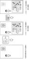
- FIG. 1 is a diagram showing an example of an overview of image acquisition according to an embodiment of the present invention.
- FIG. 1 is a diagram showing an example of an overview of image acquisition according to an embodiment of the present invention.
- FIG. 1 is a diagram showing an example of an overview of image acquisition according to an embodiment of the present invention.
- FIG. 1 is a diagram showing an example of an overview of image acquisition according to an embodiment of the present invention.
- FIG. 1 is a diagram showing an example of an overview of image acquisition according to an embodiment of the present invention.
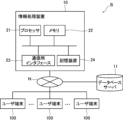
- 1 is a diagram illustrating an example of the configuration of an information processing system including an information processing device according to an embodiment of the present invention.
- FIG. 2 is an explanatory diagram of functions of an information processing device according to an embodiment of the present invention.
- FIG. 1 is a diagram showing an example of an overview of image acquisition according to an embodiment of the present invention.
- FIG. 2 is a diagram conceptually illustrating an estimation process in an information processing device according to an embodiment of the present invention.
- FIG. 2 is a diagram conceptually showing an image conversion process in an information processing device according to an embodiment of the present invention.
- FIG. 2 is a diagram showing a procedure of an image acquisition flow according to an embodiment of the present invention.
- FIG. 2 is a diagram showing a procedure of an image acquisition flow according to an embodiment of the present invention.
- FIG. 2 is a diagram showing a procedure of an image acquisition flow according to an embodiment of the present invention.
- the concept of "device” includes a single device that performs a specific function, as well as a combination of multiple devices that exist independently and in a distributed manner but work together (in cooperation) to perform a specific function.
- image data is defined as “image data.”
- the image data may be, for example, lossy compressed image data such as JPEG (Joint Photographic Experts Group) format, lossless compressed image data such as GIF (Graphics Interchange Format) or PNG (Portable Network Graphics) format, and three-dimensional image data used on a web browser such as VRML (Virtual Reality Modeling Language) format.
- the image data may also include additional information indicating information such as the file name, the date and time of shooting, and the location of shooting.
- a "user” refers to a user who uses the information processing device according to the present invention.
- Using an information processing device means using the functions of the information processing device, and includes not only directly operating the information processing device, but also using the functions of the information processing device through a device (e.g., a user terminal) that can communicate with the information processing device.
- images are acquired in virtual space by performing operations in virtual space that are similar to those performed in real space.
- An "operation performed in real space” is, for example, a photographing operation using a real camera.
- FIG. 1 shows the transition of display screens displayed on a user terminal, with the display screens transitioning in order from the left side to the right side of FIG.
- an image acquisition application an application program for image acquisition
- the display screen of the user terminal switches to a scene in the virtual space.
- the user operates his/her own avatar in the virtual space and selects a location in the virtual space where the image will be taken.
- the first display screen from the left in FIG. 1 is a screen that displays the virtual space and shows the shooting location selected by the user to acquire an image. It should be noted that the first display screen from the left in FIG. 1 shows the view seen from the user's own avatar, and other people's avatars and building objects are displayed on the display screen.
- the second display screen from the left in Fig. 1 shows a live view screen after starting the virtual camera.
- live view screen refers to an image captured in real time by a virtual camera at a specified angle of view in a dynamically changing virtual space.
- a virtual space is a reproduction of a real space using CG (Computer Graphics) or the like, and people and objects in the virtual space move in the same way as in the real space, and the scenery in the virtual space changes according to the same rules as in the real space. That is, the virtual space has the same concept of time as the real space, and the position and state of objects in the virtual space change over time.
- a setting menu for image setting conditions (corresponding to the first image setting conditions) is displayed on the display screen.
- the setting menu for the image setting conditions does not have to be displayed on the display screen.
- the "image setting conditions” are conditions for acquiring an image in a virtual space, and include, for example, the angle of view, blur, brightness, and color tone. Each of these items is for directly editing the image in the virtual space, and is different from the acquisition conditions described later.
- the image setting conditions also include the size of the image to be acquired relative to the entire display screen.
- a user who is familiar with setting image setting conditions may use the image setting condition setting menu to adjust the image to the desired image.
- a user who is not familiar with setting image setting conditions may not use the image setting condition setting menu, or may press a capture button (not shown) displayed on the display screen after roughly adjusting the image using the image setting condition setting menu.
- the capture button (not shown) is pressed, an image (corresponding to the first image) displayed on the live view screen is obtained.
- the first image is an image obtained by shooting in a virtual space, and more specifically, an image that can be obtained by shooting a space located within the angle of view of the virtual camera in the virtual space with a virtual camera.
- the virtual camera has the same performance and structure as a camera in real space, that is, a real camera, and the user can operate the virtual camera in the virtual space to shoot in the same manner as in the real space.
- the "acquisition conditions" are the acquisition conditions of an image in real space, assuming that a captured image in a virtual space is obtained by capturing (taking a picture) in real space. More specifically, the acquisition conditions include the shooting conditions of a real camera, such as the focal length, focus position, aperture (f-number), depth of field, white balance, shutter speed, brightness/contrast, and ISO sensitivity.
- subject is broadly interpreted and is not limited to a specific tangible object, but includes people, objects, and backgrounds, etc.
- the term “surrounding environment of the subject” refers to the date and time (day/night and season), the location (indoors/outdoors), and the weather (direction of the sun, etc.).
- the setting values of the setting menu in the acquisition conditions correspond to the setting values of the setting menu in the image setting conditions displayed on the immediately preceding display screen, and are estimated based on an estimation process described later.
- the setting menus for the image setting conditions and the acquisition conditions shown in Fig. 1 are display examples shown for the convenience of explanation, and are not limited to these. The same applies to the setting menus for the image setting conditions and the acquisition conditions shown in Figs. 2 to 5.
- a user familiar with operating a real camera edits the acquisition conditions from the setting menu and adjusts the first image to produce the desired image.
- the fourth display screen from the left shows the state in which the "Aperture" item in the acquisition conditions setting menu has been changed relative to the third display screen from the left.
- the first image displayed on the third display screen from the left is converted into an image displayed on the fourth display screen from the left that has a different degree of blur from the first image.
- the converted image corresponds to the third image.
- Image conversion is performed based on the image conversion process described below.
- the acquisition conditions can be edited not only immediately after shooting, but also some time after shooting.
- the acquired image and the acquisition conditions are stored in association with each other, allowing editing at the user's desired timing.
- the same virtual space situation as the previous time It is also possible to return to the same virtual space situation as the previous time and capture a different image. More specifically, information such as the date, time, location, and subject position in the virtual space is stored in association with the captured image, and by using this information, the same virtual space situation as the previous time is reproduced. In the reproduced virtual space, the user can obtain another image by changing the angle of view, for example. That is, even if the user closes the image acquisition application once and starts the image acquisition application again after a period of time, the user can redo the image acquisition from the same virtual space situation as the previous time.
- FIG. 2 like FIG. 1, shows the transition of display screens displayed on a user terminal.
- the first and second display screens from the left shown in Fig. 2 are similar to the first and second display screens from the left shown in Fig. 1, and therefore a description thereof will be omitted.
- the third and fourth display screens from the left shown in Fig. 2 are different from the third and fourth display screens from the left shown in Fig. 1.
- the third display screen from the left in Fig. 2 is a screen after shooting, and differs from the third display screen from the left in Fig. 1 in that both the image setting condition setting menu and the acquisition condition setting menu are displayed on the display screen. Therefore, the user can adjust the first image to become a desired image using one or both of the image setting conditions and the acquisition conditions. In other words, the user can adjust the first image to become a desired image using one of the image setting conditions and the acquisition conditions that is easier for the user to operate.
- the setting values of the setting menu for the acquisition conditions correspond to the setting values of the setting menu for the image setting conditions displayed on the previous display screen. Furthermore, when the setting value of either the image setting conditions or the acquisition conditions is changed, the setting value of the other is changed accordingly.
- the first image displayed on the third display screen from the left is converted to an image displayed on the fourth display screen from the left, which has a different degree of blur from the first image.
- the converted image in this case corresponds to the third image.
- the "Blur" item in the image setting condition setting menu may be changed without changing the "Aperture” item in the acquisition condition setting menu.
- the first image displayed on the third display screen from the left is converted into an image displayed on the fourth display screen from the left, which has a different degree of blur from the first image.
- the converted image in this case corresponds to the fourth image.
- the third image and the fourth image are the same image, and the third image and the fourth image are distinguished from each other by whether the acquisition conditions or the image setting conditions are set during the image conversion process.
- the third example shown in Fig. 3 differs from the example shown in Fig. 1 in that an image (corresponding to the second image) is acquired by capturing and trimming a screenshot or a part of the display screen without using a photographing function (virtual camera) provided in the image acquisition application.
- the second image can also be said to be an image obtained by recording the display screen in the virtual space.
- the user operates their own avatar in the virtual space and selects a location within the virtual space where a photo will be taken.
- the first display screen from the left in Figure 3 shows the photo location selected by the user to capture an image.
- the user takes a screenshot or trims a portion of the display screen (hereinafter also referred to as a screenshot, etc.) to capture a second image.
- the second display screen from the left in Figure 3 is the screen after taking a screenshot, etc., and displays the captured second image.
- a menu for setting the capture conditions is displayed within this display screen.
- the user edits the acquisition conditions from the acquisition conditions setting menu and adjusts the second image to the desired image.
- the third display screen from the left shows the state in which the "Aperture" item in the acquisition conditions setting menu has been changed relative to the second display screen from the left.
- the second image displayed on the third display screen from the left is converted into an image (corresponding to the fifth image) that has a different degree of blur from the second image displayed on the third display screen from the left.
- the fourth example shown in FIG. 4 differs from the example shown in FIG. 1 in that a setting menu for acquisition conditions is displayed on the live view screen.
- the user operates his/her avatar in the virtual space and selects a location within the virtual space where a photo will be taken, similar to the example shown in Figure 1.
- the first display screen from the left in Figure 4 shows the shooting location selected by the user to capture an image.
- the shooting function virtual camera
- the second display screen from the left in Figure 1 shows the live view screen after starting up the virtual camera.
- a setting menu for image setting conditions (corresponding to the second image setting conditions) is displayed on the display screen.
- the second display screen from the left automatically transitions to the third display screen from the left. More specifically, instead of the image setting condition setting menu, an acquisition condition setting menu is displayed. This allows the user to change the acquisition conditions on the live view screen before shooting and adjust the second image to a desired image.
- the second display screen from the left is automatically transitioned to the third display screen from the left, but this is not limited to the above, and the user may perform a specified operation to transition the second display screen from the left to the third display screen from the left.
- the fourth display screen from the left shows a state in which the "Aperture" item in the acquisition conditions is changed from that of the third display screen from the left, whereby the second image displayed on the third display screen from the left is converted into an image (corresponding to a fifth image) displayed on the fourth display screen from the left, which has a different degree of blur from that of the second image. Thereafter, the user can obtain a fifth image by pressing a capture button (not shown).
- the acquisition condition setting menu is displayed as shown in the third display screen from the left, but both the image setting condition setting menu and the acquisition condition setting menu may be displayed on the third display screen from the left as in the example shown in Fig. 5.
- the user can adjust the second image to a desired image by setting one or both of the image setting conditions and the acquisition conditions. More specifically, in Fig. 5, by changing the "Aperture" item in the acquisition condition setting menu, the second image displayed on the third display screen from the left is converted to an image displayed on the fourth display screen from the left, which has a different degree of blur from the second image. The converted image in this case corresponds to the fifth image.
- the "Blur" item in the image setting condition setting menu may be changed without changing the "Aperture” item in the acquisition condition setting menu.
- the "Blur" item in the image setting condition setting menu by changing the "Blur" item in the image setting condition setting menu, the second image displayed on the third display screen from the left is converted into an image displayed on the fourth display screen from the left that has a different degree of blur from the second image.
- the converted image in this case corresponds to the sixth image.
- the fifth image and the sixth image are the same image, and the fifth image and the sixth image are distinguished from each other by whether the acquisition conditions or the image setting conditions are set during the image conversion process.
- an information processing system (hereinafter referred to as "information processing system S") including an information processing device according to an embodiment of the present invention will be described with reference to FIG.
- the information processing system S is configured with an information processing device 10, a plurality of user terminals 100, and a database server 11.
- the database server 11 may be configured as a part of the information processing device 10 .
- the information processing device 10 is composed of a computer, for example, a personal computer (PC), a workstation, or a server computer.
- the information processing device 10 may be composed of one computer, or may be composed of multiple computers distributed in parallel.
- the computer constituting the information processing device 10 is a server computer, it may be a server computer for ASP (Application Service Provider), SaaS (Software as a Service), PaaS (Platform as a Service), or IaaS (Infrastructure as a Service).
- ASP Application Service Provider
- SaaS Software as a Service
- PaaS PaaS
- IaaS Infrastructure as a Service
- the computer constituting the information processing device 10 has a processor 21, a memory 22, a communication interface 23, and a storage device 24.
- the processor 21 may be composed of, for example, a CPU (Central Processing Unit), an MPU (Micro-Processing Unit), an MCU (Micro Controller Unit), a GPU (Graphics Processing Unit), a DSP (Digital Signal Processor), a TPU (Tensor Processing Unit) or an ASIC (Application Specific Integrated Circuit).
- a CPU Central Processing Unit
- MPU Micro-Processing Unit
- MCU Micro Controller Unit
- GPU Graphics Processing Unit
- DSP Digital Signal Processor
- TPU Transmissionsor Processing Unit
- ASIC Application Specific Integrated Circuit
- the memory 22 is composed of semiconductor memory such as a ROM (Read Only Memory) and a RAM (Random Access Memory).
- a program for executing this image acquisition (hereinafter, the image acquisition program) is stored in the memory 22.
- the image acquisition program is a program for causing the processor 21 to carry out each process of the information processing method described below.
- the image acquisition program may be obtained by reading it from a computer-readable recording medium, or by downloading it via a communication network such as the Internet or an intranet.
- the communication interface 23 may be, for example, a network interface card or a communication interface board.
- the computer constituting the information processing device 10 can communicate with other devices connected to the Internet or a mobile communication line, etc., via the communication interface 23.
- the storage device 24 may be, for example, a flash memory, a HDD (Hard Disc Drive), an SSD (Solid State Drive), a FD (Flexible Disc), an MO disk (Magneto-Optical disc), a CD (Compact Disc), a DVD (Digital Versatile Disc), a SD card (Secure Digital card), or a USB memory (Universal Serial Bus memory).
- the storage device 24 may be built into the computer main body constituting the information processing device 10, or may be attached to the computer main body in an external format.
- the user terminal 100 is a computer used by a user, and specifically comprises a smart device such as a smartphone, a tablet terminal, or a notebook PC (Personal Computer).
- the user terminal 100 is equipped with a processor, memory, and a communications interface.
- An image acquisition application for using the information processing system S is stored in the user terminal 100.
- the user downloads the image acquisition application from a specified site and installs it on the user terminal 100.
- the database server 11 is a cloud-type server prepared by, for example, a company that operates a service that uses the information processing device 10, specifically, a company that provides this image acquisition service.
- the information processing device 10 is connected to the database server 11 via the network N so that it can communicate with the database server 11, and can freely read out various data.
- the acquired images are stored in association with the acquisition conditions of the images in real space. More specifically, the first image, the second image, the third image, the fourth image, the fifth image, and the sixth image are stored in association with the acquisition conditions of each image.
- the acquired image and the acquisition conditions may be stored in the database server 11 as the same data file or as separate data files. If stored as the same data file, the acquisition conditions may be stored as additional information for the image. If stored as separate data files, path information to one data file may be stored in the other data file.
- the database server 11 may also have a management database that manages the correspondence between the acquired image and the acquisition conditions.
- the management database may indicate, for example, the correspondence between the identification ID of the image data file and the identification ID of the acquisition conditions data file.
- At least one of virtual space information, image setting conditions, and a method used in each of the estimation process and image conversion process described below may be stored in the database server 11. At least one of these pieces of information may be stored in association with the acquired image and acquisition conditions.
- Virtual space information refers to information such as the time of day, weather, season, location, and subject position in the virtual space at the time the image was captured. By using this information, the virtual space at the time the image was captured is reproduced.
- the acquired images and acquisition conditions, etc. may not be stored in the database server 11 but may be stored in the user terminal 100 of each user.
- the information processing device 10 has an acquisition processing unit 31, an estimation processing unit 32, a change acceptance unit 33, a display processing unit 34, and a storage processing unit 35.
- These functional units are realized by cooperation between hardware devices included in a computer constituting the information processing device 10 and a program (i.e., software) installed in the computer. Each functional unit will be described below.
- the acquisition processing unit 31 executes an acquisition process for acquiring an image based on at least a part of the display data constituting the display of the virtual space.
- Display data refers to an image (image data) displayed on the entire screen of the user terminal 100.
- image based on at least a part of the display data may be an image displayed on the entire screen of the user terminal 100, or may be an image acquired by capturing and trimming a part of the display screen of the user terminal 100, as in the example shown in Fig. 3.
- the image acquired by the acquisition process is, for example, the first image or the second image described above.
- the acquisition processing unit 31 acquires a first image setting condition for acquiring a first image, and also acquires a second image setting condition for acquiring a second image.
- the first image or the second image is also simply referred to as an "image”
- the first image setting condition and the second image setting condition are also simply referred to as an "image setting condition.”
- the first image and the first image setting conditions are acquired by pressing a capture button (not shown).
- the second image and the second image setting conditions are acquired by taking a screenshot or the like.
- the second image and the second image setting conditions are acquired when a predetermined time has elapsed without changing the display on the display screen on the live view screen, or when a predetermined operation by the user is accepted.
- the estimation processing unit 32 executes an estimation process for estimating the acquisition conditions. More specifically, the estimation processing unit 32 estimates acquisition conditions of the first image in real space based on at least one of the first image and the first image setting conditions, and estimates acquisition conditions of the second image in real space based on at least one of the second image and the second image setting conditions.
- the "acquisition conditions” include the actual shooting conditions of the camera, and more specifically, the focal length, focus position, aperture, depth of field, white balance, shutter speed, brightness/contrast, and ISO sensitivity.
- “Estimation” is interpreted broadly and does not limit the method used to acquire the acquisition conditions.
- the "method of estimating the acquisition conditions” includes all methods for acquiring the acquisition conditions, such as “estimating” the acquisition conditions using a trained model generated in advance by machine learning, “calculating” the acquisition conditions using a simulation with an optical calculation model, “analyzing” an image using image analysis technology, or “determining” an output value corresponding to an input value using a lookup table, etc.
- FIG. 8 is a diagram showing input information, the method used, and output information. It should be noted that not all of the input information shown in FIG. 8 is used, but the input information is selected depending on the method to be used, the accuracy of the output information required, and the like. Hereinafter, a specific description will be given of a case where the estimation process is performed using the above three examples.
- the estimation processing unit 32 may estimate the image acquisition conditions in real space using a trained model that has been generated in advance by machine learning.
- Machine learning here refers to analyzing the relationship between input information (at least one of the acquired image and image setting conditions) and output information (acquisition conditions) that are prepared in advance as learning data, and constructing a mathematical model (function) that defines that relationship.
- acquisition conditions can be obtained as output information.
- the input information and output information prepared in advance may be images actually captured in real space and the capture conditions at that time.
- the acquisition conditions estimated by the trained model do not have to be strict conditions for acquiring an image in real space, but may be rough acquisition conditions assuming that the image is acquired in real space.
- the estimation processing unit 32 estimates the acquisition conditions of the first image in real space using the trained model based on at least one of the first image and the first image setting conditions. That is, the estimation processing unit 32 inputs at least one of the first image and the first image setting conditions to the trained model, thereby obtaining the acquisition conditions as output information.
- the estimation processing unit 32 estimates the acquisition conditions of the second image in real space based on the second image using the trained model. That is, the estimation processing unit 32 obtains the acquisition conditions as output information by inputting the second image to the trained model.
- the estimation processing unit 32 estimates the acquisition conditions of the second image in real space using the trained model based on at least one of the second image and the second image setting conditions. That is, the estimation processing unit 32 inputs at least one of the second image and the second image setting conditions to the trained model, thereby obtaining the acquisition conditions as output information.
- the estimation processing unit 32 may estimate the image acquisition conditions in real space by using an optical simulation based on an optical calculation model.
- Optical simulation is a simulation that calculates the brightness and optical characteristics of each part in real space and virtual space based on the optical behavior and light path in that part, and derives the image setting conditions in the virtual space and the image acquisition conditions in the real space from one another.
- the estimation processing unit 32 calculates the acquisition conditions for the first image in real space by optical simulation using the first image setting conditions and information regarding the subject displayed in the first image.
- the estimation processing unit 32 calculates the acquisition conditions for the second image in real space by optical simulation using the second image setting conditions and information about the subject displayed in the second image.
- Information about the subject includes the position of the subject displayed in the first image (second image), the size of the subject, the distance from the photographer's position to the subject, and the distance between the subjects.
- Information about the subject may be obtained from virtual space information stored in the database server 11, or may be obtained by performing image analysis on the first image (second image) using known image analysis technology.
- the estimation processing unit 32 may estimate the acquisition conditions of the image in real space using a lookup table (hereinafter also referred to as an LUT) in which a correspondence relationship between image setting conditions and acquisition conditions is set in advance. 1 and 2, the estimation processing unit 32 determines the acquisition conditions of the first image in real space by using an LUT in which a correspondence relationship between the first image setting conditions and the acquisition conditions is set in advance. For example, if the setting value of "Bokeh" in the first image setting conditions is 3, the setting value of "Aperture” in the acquisition conditions may be set to 4 by referring to the LUT. In the example shown in FIGS. 4 and 5, the estimation processing unit 32 determines the acquisition conditions for the second image in real space using an LUT in which the correspondence relationship between the second image setting conditions and the acquisition conditions is set in advance.
- a lookup table hereinafter also referred to as an LUT
- the estimation processing unit 32 may pre-set a numerical range of the acquisition conditions corresponding to the image setting conditions in the LUT, perform image analysis on the acquired image using a known image analysis technique, and reflect the results in the LUT to determine (estimate) the acquisition conditions from within the numerical range.
- the numerical range of the "aperture" of the acquisition conditions corresponding to the setting value 3 of the "blur" of the image setting conditions is preset as 4.5 to 8.0.
- the estimation processing unit 32 may use the LUT and image analysis technology to estimate the image acquisition conditions in real space based on both the acquired image and the image setting conditions.
- the change receiving unit 33 estimates the image acquisition conditions in the real space, and then executes a change receiving process to receive changes to the estimated image acquisition conditions. That is, as shown in FIGS. 1 to 5, when the acquisition conditions are edited or changed by the user, the change acceptance unit 33 accepts the change to the acquisition conditions. More specifically, in the example shown in Figures 1 and 2, the change acceptance unit 33 estimates the acquisition conditions of the first image in real space, and then performs a process (corresponding to the first change acceptance process) to accept changes to the estimated acquisition conditions of the first image. In addition, in the examples shown in Figures 3 to 5, the change acceptance unit 33 estimates the acquisition conditions of the second image in real space, and then executes a process (corresponding to a third change acceptance process) to accept changes to the estimated acquisition conditions of the second image.
- the change accepting unit 33 may accept a change to the image setting conditions after estimating the image acquisition conditions in the real space. That is, as shown in FIGS. 2 and 5, when the image setting conditions are edited or changed by the user, the change accepting unit 33 accepts a change to the image setting conditions. More specifically, in the example shown in Figure 2, the change acceptance unit 33 estimates the acquisition conditions of the first image in real space, and then performs a process (corresponding to a second change acceptance process) to accept changes to the first image setting conditions. In addition, in the example shown in Figure 5, the change receiving unit 33 estimates the acquisition conditions of the second image in real space, and then executes a process (corresponding to a fourth change receiving process) to receive changes to the second image setting conditions.
- the display processing unit 34 executes a display process for displaying, on the display screen, an image obtained by converting the image based on the changed acquisition conditions. More specifically, in the example shown in Figures 1 and 2, after the first change acceptance process, the display processing unit 34 executes a process (corresponding to the first display process) of displaying on the display screen a third image obtained by converting the first image based on the changed acquisition conditions. In addition, in the example shown in Figures 3 to 5, after the third change acceptance process, the display processing unit 34 executes a process (corresponding to the third display process) of displaying on the display screen a fifth image obtained by converting the second image based on the changed acquisition conditions.
- the display processing unit 34 After the change acceptance process, the display processing unit 34 also executes a display process for converting the image based on the changed image setting conditions and displaying the resulting image on the display screen. More specifically, in the example shown in Fig. 2, the display processing unit 34 executes a process (corresponding to the second display process) of displaying a fourth image obtained by converting the first image based on the changed first image setting condition on the display screen after the second change acceptance process. Also, in the example shown in Fig. 5, the display processing unit 34 executes a process (corresponding to the fourth display process) of displaying a sixth image obtained by converting the second image based on the changed second image setting condition on the display screen after the fourth change acceptance process.
- FIG. 9 is a diagram showing input information, the method used, and output information. It should be noted that not all of the input information shown in FIG. 9 is used, but the input information is selected depending on the method to be used, the accuracy of the output information required, and the like. Hereinafter, the case where the image conversion process is executed using the above two examples will be specifically described.
- the display processing unit 34 executes image conversion processing using a trained model that has been generated in advance by machine learning.
- the display processing unit 34 estimates the converted image using the trained model based on the image before conversion, the image setting conditions before the change, and the image setting conditions after the change, as shown in Fig. 9.
- the display processing unit 34 may estimate the converted image using the trained model based on the image before conversion, the acquisition conditions before the change, and the acquisition conditions after the change. That is, when image setting conditions are not used as in the example shown in Figure 3, the display processing unit 34 uses the acquisition conditions before and after the change as input information, but for other examples (examples shown in Figures 1, 2, 4 and 5), at least one of the acquisition conditions before and after the change and the image setting conditions before and after the change may be used as input information.
- the "machine learning” referred to here is the analysis of the relationship between input information (the image before conversion, and the image setting conditions before and after the change, or the acquisition conditions before and after the change) that has been prepared in advance as learning data, and output information (the image after conversion), and constructing a mathematical model (function) that specifies that relationship.
- a converted image By inputting input information according to each of the examples in Figures 1 to 5 into a trained model generated by such machine learning, a converted image can be obtained as output information.
- the display processing unit 34 executes a process of generating a converted image using an optical simulation based on an optical calculation model. More specifically, the display processing unit 34 may generate an image by optical simulation using the above-mentioned information on the subject and at least one of the changed acquisition conditions and the changed image setting conditions.
- the storage processing unit 35 executes a storage process for storing the acquired images in association with the acquisition conditions of the images in real space. More specifically, the storage processing unit 35 stores the first image, the second image, the third image, the fourth image, the fifth image, and the sixth image in association with the acquisition conditions of each image.
- the storage processing unit 35 may store the associated images and acquisition conditions in, for example, the database server 11 and/or the user terminal 100 . Furthermore, the storage processing unit 35 may store the virtual space information, the image setting conditions, and at least one of the methods used in each of the estimation process and the image conversion process in association with the image and the acquisition conditions.
- FIG. 10 to 12 each explain a different image acquisition flow, with the image acquisition flow shown in Figure 10 corresponding to the example shown in Figures 1 and 2, the image acquisition flow shown in Figure 11 corresponding to the example shown in Figure 3, and the image acquisition flow shown in Figure 12 corresponding to the example shown in Figures 4 and 5.
- Each step in the image acquisition flow shown in Figures 10 to 12 corresponds to each element constituting the information processing method of the present invention.
- This image acquisition flow is started when an image acquisition application installed in the user terminal 100 is started.
- the processor 21 accepts the use of the image capture function (virtual camera) provided in the image acquisition application (S001). As a result, the display screen of the user terminal 100 switches to a live view screen, and a setting menu for the first image setting conditions is displayed on the display screen.
- the image capture function virtual camera
- S001 image acquisition application
- the processor 21 accepts the execution of shooting (S002).
- the processor 21 acquires a first image obtained by shooting in the virtual space (S003).
- the processor 21 acquires a first image setting condition for acquiring the first image (S004).
- processor 21 estimates the acquisition conditions of the first image in real space, assuming that the first image is obtained by acquisition in real space (S005). Specifically, processor 21 estimates the acquisition conditions of the first image in real space based on at least one of the acquired first image and the first image setting conditions. More specifically, processor 21 estimates the acquisition conditions of the first image in real space using the aforementioned methods such as the learned model and optical simulation.
- the processor 21 issues an instruction to display the acquisition conditions on the display screen (S006).
- a setting menu for the acquisition conditions is displayed on the display screen of the user terminal 100, as shown in FIGS.
- the processor 21 may display a setting menu for acquisition conditions on the display screen instead of the setting menu for the first image setting conditions, as in the example shown in Figure 1, or may display both the setting menu for the first image setting conditions and the setting menu for the acquisition conditions on the display screen, as in the example shown in Figure 2.
- the processor 21 determines whether a change has been made to the acquisition condition (or the first image setting condition) (S007). Specifically, when the user edits the acquisition condition (or the first image setting condition) from the setting menu, the processor 21 determines that a change has been made to the acquisition condition (or the first image setting condition) and accepts the change. After accepting the change, the processor 21 converts the first image into a third image (or a fourth image) based on the changed acquisition condition (or the first image setting condition) (S008). More specifically, the processor 21 converts the first image into a third image (or a fourth image) using the above-mentioned methods such as the learned model and optical simulation.
- the processor 21 displays the third image (or the fourth image) obtained by converting the first image on the display screen (S009). It should be noted that, in step S007, if the processor 21 determines that no change has been made to the acquisition conditions (or the first image setting conditions), it skips steps S008 and S009.
- this image acquisition flow ends. This image acquisition flow will be repeated each time an image is acquired.
- This image acquisition flow is started when an image acquisition application installed in the user terminal 100 is started.
- the processor 21 accepts the execution of a screenshot or the like by performing an operation such as taking a screenshot of the display screen (S101). As a result, the processor 21 acquires a second image obtained by recording the display screen of the virtual space (S102). The processor 21 also acquires second image setting conditions for acquiring the second image (S103). Next, the processor 21 estimates the acquisition conditions of the second image in the real space assuming that the second image is acquired in the real space (S104). The specific estimation method is the same as the image acquisition flow shown in FIG. 10, so a description thereof will be omitted.
- the processor 21 issues an instruction to display the acquisition conditions on the display screen (S105).
- a setting menu for the acquisition conditions is displayed on the display screen of the user terminal 100, as shown in FIG.
- the processor 21 determines whether a change has been made to the acquisition conditions (S106). If the user edits the acquisition conditions from the setting menu, the processor 21 determines that a change has been made to the acquisition conditions and accepts the change. After accepting the change, the processor 21 converts the second image into a fifth image based on the changed acquisition conditions (S107).
- the specific conversion method is the same as the image acquisition flow shown in FIG. 10, so the description is omitted.
- the processor 21 displays the fifth image obtained by converting the second image on the display screen (S108). If the processor 21 determines in step S106 that no change has been made to the acquisition conditions, it skips steps S107 and S108.
- this image acquisition flow ends. This image acquisition flow will be repeated each time an image is acquired.
- This image acquisition flow is started when an image acquisition application installed in the user terminal 100 is started.
- the processor 21 accepts the use of the image capture function (virtual camera) provided in the image acquisition application (S201). As a result, the display screen of the user terminal 100 switches to a live view screen, and a setting menu for the second image setting conditions is displayed on the display screen.
- the image capture function virtual camera
- the processor 21 acquires a second image obtained by recording the display screen of the virtual space (S202).
- the processor 21 also acquires second image setting conditions for acquiring the second image (S203).
- the processor 21 estimates the acquisition conditions of the second image in the real space on the assumption that the second image is obtained by acquisition in the real space (S204).
- the processor 21 estimates the acquisition conditions of the second image in the real space based on at least one of the acquired second image and the second image setting conditions.
- the specific estimation method is the same as the image acquisition flow shown in FIG. 10, and therefore the description will be omitted.
- the processor 21 issues an instruction to display the acquisition conditions on the display screen (S205).
- a setting menu for the acquisition conditions is displayed on the display screen of the user terminal 100, as shown in FIGS.
- the processor 21 may display a setting menu for the acquisition conditions on the display screen instead of the setting menu for the second image setting conditions, as in the example shown in Figure 4, or may display both the setting menu for the second image setting conditions and the setting menu for the acquisition conditions on the display screen, as in the example shown in Figure 5.
- the processor 21 determines whether a change has been made to the acquisition conditions (or the second image setting conditions) (S206). If the user edits the acquisition conditions (or the second image setting conditions) from the setting menu, the processor 21 determines that a change has been made to the acquisition conditions (or the second image setting conditions) and accepts the change. After accepting the change, the processor 21 converts the second image into a fifth image (or a sixth image) based on the changed acquisition conditions (or the second image setting conditions) (S207).
- the specific conversion method is the same as the image acquisition flow shown in FIG. 10, so a description thereof will be omitted.
- the processor 21 displays on the display screen the fifth image (or sixth image) obtained by converting the second image (S208). It should be noted that, in step S206, if the processor 21 determines that no change has been made to the acquisition conditions (or the second image setting conditions), it skips steps S207 and S208. Thereafter, when the user presses a shooting button (not shown) displayed on the display screen, the processor 21 accepts the execution of shooting (S209).
- the main image acquisition flow ends when the above series of processes are completed. The main image acquisition flow is repeated every time a main image is acquired.
- steps S201 to S208 of the image acquisition flow shown in FIG. 12 may be executed before step S002 of the image acquisition flow shown in FIG. 10, or conversely, steps S002 to S009 of the image acquisition flow shown in FIG. 10 may be executed after step S208 of the image acquisition flow shown in FIG. 12.
- an image editing flow may be executed. More specifically, after step S009 shown in Fig. 10, the processor 21 associates the third image (fourth image) with the acquisition conditions and stores them in the database server 11. Thereafter, the image acquisition flow shown in Fig. 10 ends.
- the processor 21 displays the same screen as the display screen displayed in step S009. Specifically, the processor 21 acquires the third image (fourth image) and acquisition conditions from the database server 11. As a result, the display screen displays the third image (fourth image) and a setting menu for the acquisition conditions.
- the display screen displays the third image (fourth image) and both the setting menus for the acquisition conditions and the image setting conditions.
- the processor 21 determines that a change has been made to the acquisition conditions (or image setting conditions) and accepts the change. After accepting the change, the processor 21 converts the third image (fourth image) into another image based on the changed acquisition conditions (or image setting conditions).
- the image editing flow ends when the series of processes described above is completed. Similarly, after the image acquisition flows shown in FIGS. 11 and 12 are completed, the image editing flow described above may be performed.
- the processor 21 may store in the database server 11 information about the virtual space when an image is acquired in the image acquisition flow shown in Figures 10 to 12, and execute step S001 and subsequent steps of the image acquisition flow shown in Figure 10 from the same virtual space situation as the previous time. Specifically, when a user performs a predetermined operation after starting an image application, the processor 21 acquires, for example, information on the virtual space stored in the database server 11 during the previous image acquisition flow. This causes the same virtual space situation as the previous time, i.e., the date, time, location, and subject position in the virtual space, to be reproduced on the display screen.
- step S001 the user selects a location in the virtual space where a photograph will be taken, and selects a menu related to the photographing function from the display screen of the user terminal 100, whereby the processor 21 executes each step from step S001 onwards.
- step S101 virtual space information at the time of the previous image acquisition stored in the database server 11 may be acquired.
- step S201 virtual space information at the time of the previous image acquisition stored in the database server 11 may be acquired before step S201.
- the image is a first image obtained by photographing within the virtual space, or a second image obtained by recording a display screen of the virtual space.
- This allows an image according to the user's preference to be smoothly acquired when taking a picture in a virtual space using a shooting function as shown in Figures 1 and 2.
- recording a display screen of a virtual space more specifically, when taking a screenshot as shown in Figure 3, or when recording a live view screen of a virtual space as shown in Figures 4 and 5, an image according to the user's preference to be smoothly acquired.
- the processor 21 estimates the image acquisition conditions in real space using a trained model that has been generated in advance by machine learning. This makes it possible to estimate the rough acquisition conditions assuming that the image was acquired in real space. Also, depending on the accuracy of the trained model, it is possible to estimate more accurate acquisition conditions.
- the processor 21 accepts a first image setting condition for acquiring the first image in the acquisition process.
- the processor estimates an acquisition condition of the first image in real space based on at least one of the first image and the first image setting condition. This allows the user to smoothly obtain images according to their preferences when taking pictures using the photography function in a virtual space as shown in FIGS.
- the processor 21 estimates the acquisition conditions of the first image in real space using a trained model created in advance by machine learning based on at least one of the first image and the first image setting conditions. This makes it possible to estimate rough capture conditions when an image is captured in real space using a capture function in a virtual space as shown in Figures 1 and 2. In addition, more accurate capture conditions can be estimated depending on the accuracy of the trained model.
- the processor 21 estimates the acquisition conditions of the first image in real space by optical simulation using the first image setting conditions and information about the subject displayed in the first image.
- the processor 21 executes a first change acceptance process for accepting a change to the estimated acquisition condition of the first image after estimating the acquisition condition of the first image in the estimation process, and executes a first display process for displaying a third image obtained by converting the first image based on the changed acquisition condition on the display screen after the first change acceptance process.
- a first change acceptance process for accepting a change to the estimated acquisition condition of the first image after estimating the acquisition condition of the first image in the estimation process
- a first display process for displaying a third image obtained by converting the first image based on the changed acquisition condition on the display screen after the first change acceptance process.
- the processor 21 executes a second change acceptance process for accepting a change to the first image setting condition after estimating the acquisition condition of the first image in the real space in the estimation process, and executes a second display process for displaying a fourth image obtained by converting the first image based on the changed first image setting condition on the display screen after the second change acceptance process.
- the processor 21 accepts second image setting conditions for acquiring the second image in the acquisition process.
- the processor estimates acquisition conditions for the second image in real space based on at least one of the second image and the second image setting conditions. This makes it possible to smoothly obtain images that meet the user's preferences when recording the display screen of the virtual space as shown in FIGS.
- the processor 21 estimates the acquisition conditions of the second image in real space using a trained model created in advance by machine learning based on at least one of the second image and the second image setting conditions. This makes it possible to estimate rough capture conditions when recording a display screen in a virtual space, assuming that an image is captured in real space, as shown in Figures 3 to 5. In addition, more accurate capture conditions can be estimated depending on the accuracy of the trained model.
- the processor 21 estimates the acquisition conditions of the second image in real space by optical simulation using the second image setting conditions and information about the subject displayed in the second image.
- the processor 21 estimates the acquisition conditions of the second image in real space by optical simulation using the second image setting conditions and information about the subject displayed in the second image.
- the processor 21 executes a third change acceptance process for accepting a change to the estimated acquisition condition of the second image after estimating the acquisition condition of the second image in the estimation process, and a third display process for displaying a fifth image obtained by converting the second image based on the changed acquisition condition on the display screen after the third change acceptance process.
- a third change acceptance process for accepting a change to the estimated acquisition condition of the second image after estimating the acquisition condition of the second image in the estimation process
- a third display process for displaying a fifth image obtained by converting the second image based on the changed acquisition condition on the display screen after the third change acceptance process.
- the processor 21 executes a fourth change acceptance process for accepting a change to the second image setting condition after estimating the acquisition condition of the second image in the real space in the estimation process, and executes a fourth display process for displaying a sixth image obtained by converting the second image based on the changed second image setting condition on the display screen after the fourth change acceptance process.
- the processor 21 executes a storage process for storing the acquired image in association with the acquisition conditions of the image in real space. This allows the user to utilize the acquired image and acquisition conditions. For example, even after some time has passed since the image was taken, the acquired image can be edited using the acquisition conditions. Alternatively, the acquired image and acquisition conditions can be shared between users, and can be used as a reference the next time an image is acquired.
- the information processing device 10 may be configured by a server computer. However, this is not limiting, and for example, the information processing device of the present invention may be configured by a user terminal.
- the information processing device and the processor included in the information processing device of the present invention include various processors, such as a CPU, which is a general-purpose processor that executes software (programs) and functions as various processing units.
- the various processors also include programmable logic devices (PLDs), which are processors whose circuit configuration can be changed after manufacture, such as field programmable gate arrays (FPGAs).
- PLDs programmable logic devices
- FPGAs field programmable gate arrays
- various processors include dedicated electric circuits such as ASICs (Application Specific Integrated Circuits), which are processors having a circuit configuration designed exclusively for performing specific processing.
- the information processing device of the present invention and one of the processing units possessed by the information processing device may be configured using one of the various processors described above, or may be configured using a combination of two or more processors of the same or different types, for example, a combination of multiple FPGAs, or a combination of an FPGA and a CPU, etc.
- the multiple functional units of the information processing device of the present invention may be configured by one of various processors, or two or more of the multiple functional units may be collectively configured by one processor.
- one or more CPUs may be combined with software to form one processor, and this processor may function as multiple functional units.
- a processor may be used that realizes the functions of the information processing device of the present invention and the entire system including multiple functional units in the information processing device on a single IC (Integrated Circuit) chip, as typified by a SoC (System on Chip).
- the hardware configuration of the various processors described above may be an electric circuit (Circuitry) that combines circuit elements such as semiconductor elements.
Landscapes
- Engineering & Computer Science (AREA)
- General Engineering & Computer Science (AREA)
- Theoretical Computer Science (AREA)
- Human Computer Interaction (AREA)
- Physics & Mathematics (AREA)
- General Physics & Mathematics (AREA)
- Multimedia (AREA)
- Signal Processing (AREA)
- Processing Or Creating Images (AREA)
Priority Applications (3)
| Application Number | Priority Date | Filing Date | Title |
|---|---|---|---|
| EP24780160.8A EP4693210A1 (en) | 2023-03-30 | 2024-03-25 | Information processing device, information processing method, program, and recording medium |
| CN202480018113.6A CN120826715A (zh) | 2023-03-30 | 2024-03-25 | 信息处理装置、信息处理方法、程序及记录介质 |
| JP2025510839A JPWO2024204042A1 (https=) | 2023-03-30 | 2024-03-25 |
Applications Claiming Priority (2)
| Application Number | Priority Date | Filing Date | Title |
|---|---|---|---|
| JP2023-055938 | 2023-03-30 | ||
| JP2023055938 | 2023-03-30 |
Publications (1)
| Publication Number | Publication Date |
|---|---|
| WO2024204042A1 true WO2024204042A1 (ja) | 2024-10-03 |
Family
ID=92905306
Family Applications (1)
| Application Number | Title | Priority Date | Filing Date |
|---|---|---|---|
| PCT/JP2024/011655 Ceased WO2024204042A1 (ja) | 2023-03-30 | 2024-03-25 | 情報処理装置、情報処理方法、プログラム、及び記録媒体 |
Country Status (4)
| Country | Link |
|---|---|
| EP (1) | EP4693210A1 (https=) |
| JP (1) | JPWO2024204042A1 (https=) |
| CN (1) | CN120826715A (https=) |
| WO (1) | WO2024204042A1 (https=) |
Citations (5)
| Publication number | Priority date | Publication date | Assignee | Title |
|---|---|---|---|---|
| JP2009266159A (ja) | 2008-04-30 | 2009-11-12 | Konami Digital Entertainment Co Ltd | 画像処理プログラム、画像処理装置及び画像処理制御方法 |
| JP2020102687A (ja) * | 2018-12-20 | 2020-07-02 | キヤノン株式会社 | 情報処理装置、画像処理装置、画像処理方法、及びプログラム |
| WO2020262261A1 (ja) * | 2019-06-28 | 2020-12-30 | ソニー株式会社 | 情報処理装置、情報処理方法及びプログラム |
| JP2022093262A (ja) * | 2020-12-11 | 2022-06-23 | キヤノン株式会社 | 画像処理装置、画像処理装置の制御方法およびプログラム |
| WO2022186141A1 (ja) * | 2021-03-04 | 2022-09-09 | パナソニック インテレクチュアル プロパティ コーポレーション オブ アメリカ | ニューラルネットワークのネットワークパラメータの学習方法、カメラパラメータの算出方法、及びプログラム |
-
2024
- 2024-03-25 JP JP2025510839A patent/JPWO2024204042A1/ja active Pending
- 2024-03-25 WO PCT/JP2024/011655 patent/WO2024204042A1/ja not_active Ceased
- 2024-03-25 EP EP24780160.8A patent/EP4693210A1/en active Pending
- 2024-03-25 CN CN202480018113.6A patent/CN120826715A/zh active Pending
Patent Citations (5)
| Publication number | Priority date | Publication date | Assignee | Title |
|---|---|---|---|---|
| JP2009266159A (ja) | 2008-04-30 | 2009-11-12 | Konami Digital Entertainment Co Ltd | 画像処理プログラム、画像処理装置及び画像処理制御方法 |
| JP2020102687A (ja) * | 2018-12-20 | 2020-07-02 | キヤノン株式会社 | 情報処理装置、画像処理装置、画像処理方法、及びプログラム |
| WO2020262261A1 (ja) * | 2019-06-28 | 2020-12-30 | ソニー株式会社 | 情報処理装置、情報処理方法及びプログラム |
| JP2022093262A (ja) * | 2020-12-11 | 2022-06-23 | キヤノン株式会社 | 画像処理装置、画像処理装置の制御方法およびプログラム |
| WO2022186141A1 (ja) * | 2021-03-04 | 2022-09-09 | パナソニック インテレクチュアル プロパティ コーポレーション オブ アメリカ | ニューラルネットワークのネットワークパラメータの学習方法、カメラパラメータの算出方法、及びプログラム |
Non-Patent Citations (1)
| Title |
|---|
| See also references of EP4693210A1 |
Also Published As
| Publication number | Publication date |
|---|---|
| CN120826715A (zh) | 2025-10-21 |
| EP4693210A1 (en) | 2026-02-11 |
| JPWO2024204042A1 (https=) | 2024-10-03 |
Similar Documents
| Publication | Publication Date | Title |
|---|---|---|
| JP6899002B2 (ja) | 画像処理方法、装置、コンピュータ読み取り可能記憶媒体及び電子機器 | |
| KR101655078B1 (ko) | 움직이는 사진 생성 방법 및 장치 | |
| AU2010257231B2 (en) | Collaborative image capture | |
| KR101720774B1 (ko) | 디지털 촬영 장치 및 그의 사진 제공 방법 | |
| CN115836319B (zh) | 图像处理方法及装置 | |
| CN113989387B (zh) | 相机拍摄参数调整方法、装置及电子设备 | |
| WO2015180684A1 (zh) | 基于移动终端的摄影仿真教学方法及系统、存储介质 | |
| CN106844722A (zh) | 基于Kinect设备的合影系统及方法 | |
| CN109660714A (zh) | 基于ar的图像处理方法、装置、设备及存储介质 | |
| CN115623313B (zh) | 图像处理方法、图像处理装置、电子设备、存储介质 | |
| CN107451953A (zh) | 一种合影照片生成方法及其装置、电子设备 | |
| WO2025092175A1 (zh) | 虚拟对象生成方法、装置、计算机设备及存储介质 | |
| JP2019169985A (ja) | 画像処理装置 | |
| KR101672691B1 (ko) | 소셜 네트워크 서비스 플랫폼에서 이모티콘 생성 방법 및 장치 | |
| US11367229B2 (en) | Image processing apparatus, image processing method, and storage medium | |
| JP7175772B2 (ja) | 撮像装置及び撮像方法 | |
| WO2024204042A1 (ja) | 情報処理装置、情報処理方法、プログラム、及び記録媒体 | |
| CN114745516A (zh) | 全景视频的生成方法、装置、存储介质及电子设备 | |
| JP7668203B2 (ja) | 画像処理装置、画像処理方法、プログラム及び記録媒体 | |
| CN106791358B (zh) | 终端拍照方法、装置及终端 | |
| US20210409611A1 (en) | Imaging apparatus, image shooting processing method, and storage medium | |
| JP2024046217A (ja) | 撮像装置および撮像システム | |
| KR20160128900A (ko) | 움직이는 효과 기반의 움직이는 사진 생성 방법 및 장치 | |
| JP2013102351A (ja) | 撮像装置とその制御方法及びプログラムに関する | |
| WO2024180904A1 (ja) | データ取得装置、画像取得装置、データ構造、データ取得方法、画像取得方法、プログラム、及び記録媒体 |
Legal Events
| Date | Code | Title | Description |
|---|---|---|---|
| 121 | Ep: the epo has been informed by wipo that ep was designated in this application |
Ref document number: 24780160 Country of ref document: EP Kind code of ref document: A1 |
|
| WWE | Wipo information: entry into national phase |
Ref document number: 202480018113.6 Country of ref document: CN |
|
| ENP | Entry into the national phase |
Ref document number: 2025510839 Country of ref document: JP Kind code of ref document: A |
|
| WWE | Wipo information: entry into national phase |
Ref document number: 2025510839 Country of ref document: JP |
|
| WWE | Wipo information: entry into national phase |
Ref document number: 202517094195 Country of ref document: IN |
|
| WWP | Wipo information: published in national office |
Ref document number: 202480018113.6 Country of ref document: CN |
|
| WWE | Wipo information: entry into national phase |
Ref document number: 2024780160 Country of ref document: EP |
|
| NENP | Non-entry into the national phase |
Ref country code: DE |
|
| WWP | Wipo information: published in national office |
Ref document number: 202517094195 Country of ref document: IN |
|
| ENP | Entry into the national phase |
Ref document number: 2024780160 Country of ref document: EP Effective date: 20251030 |
|
| ENP | Entry into the national phase |
Ref document number: 2024780160 Country of ref document: EP Effective date: 20251030 |
|
| ENP | Entry into the national phase |
Ref document number: 2024780160 Country of ref document: EP Effective date: 20251030 |
|
| ENP | Entry into the national phase |
Ref document number: 2024780160 Country of ref document: EP Effective date: 20251030 |
|
| ENP | Entry into the national phase |
Ref document number: 2024780160 Country of ref document: EP Effective date: 20251030 |
|
| ENP | Entry into the national phase |
Ref document number: 2024780160 Country of ref document: EP Effective date: 20251030 |
|
| ENP | Entry into the national phase |
Ref document number: 2024780160 Country of ref document: EP Effective date: 20251030 |
|
| ENP | Entry into the national phase |
Ref document number: 2024780160 Country of ref document: EP Effective date: 20251030 |
|
| WWP | Wipo information: published in national office |
Ref document number: 2024780160 Country of ref document: EP |