WO2024203995A1 - アタッチメントレンズ - Google Patents
アタッチメントレンズ Download PDFInfo
- Publication number
- WO2024203995A1 WO2024203995A1 PCT/JP2024/011563 JP2024011563W WO2024203995A1 WO 2024203995 A1 WO2024203995 A1 WO 2024203995A1 JP 2024011563 W JP2024011563 W JP 2024011563W WO 2024203995 A1 WO2024203995 A1 WO 2024203995A1
- Authority
- WO
- WIPO (PCT)
- Prior art keywords
- lens
- attachment
- line
- less
- power
- Prior art date
- Legal status (The legal status is an assumption and is not a legal conclusion. Google has not performed a legal analysis and makes no representation as to the accuracy of the status listed.)
- Ceased
Links
Images

Classifications
-
- G—PHYSICS
- G02—OPTICS
- G02B—OPTICAL ELEMENTS, SYSTEMS OR APPARATUS
- G02B15/00—Optical objectives with means for varying the magnification
- G02B15/02—Optical objectives with means for varying the magnification by changing, adding, or subtracting a part of the objective, e.g. convertible objective
- G02B15/10—Optical objectives with means for varying the magnification by changing, adding, or subtracting a part of the objective, e.g. convertible objective by adding a part, e.g. close-up attachment
-
- G—PHYSICS
- G02—OPTICS
- G02B—OPTICAL ELEMENTS, SYSTEMS OR APPARATUS
- G02B13/00—Optical objectives specially designed for the purposes specified below
- G02B13/001—Miniaturised objectives for electronic devices, e.g. portable telephones, webcams, PDAs, small digital cameras
- G02B13/0015—Miniaturised objectives for electronic devices, e.g. portable telephones, webcams, PDAs, small digital cameras characterised by the lens design
-
- G—PHYSICS
- G02—OPTICS
- G02B—OPTICAL ELEMENTS, SYSTEMS OR APPARATUS
- G02B21/00—Microscopes
- G02B21/02—Objectives
Definitions
- This disclosure relates to an attachment lens, in particular an attachment lens that can achieve microscopic and high-resolution optical characteristics by being attached in front of an imaging lens.
- Attachment lenses are known as optical elements that can be attached to an imaging lens to change the performance and use of the imaging lens. There are attachment lenses that change the angle of view and attachment lenses that change the magnification, as well as attachment lenses that are attached to the imaging subject side of the imaging lens and attachment lenses that are attached to the image side of the imaging lens.
- Patent Documents 1 and 2 disclose lenses that have the function of widening the angle of view as attachment lenses that are attached to the imaging subject side of an imaging lens.
- imaging lenses are primarily designed to provide excellent optical performance on their own, and generally, attaching an attachment lens disrupts the aberration balance, often resulting in a deterioration in the optical performance of the entire optical system, including the imaging lens and attachment lens.
- the present invention aims to provide an attachment lens that can be attached to an existing imaging lens without degrading the overall optical performance, and enables the observation of minute objects with high resolution.
- An attachment lens comprises, from the object side, a first lens having positive refractive power, a second lens having negative refractive power, and a third lens having positive refractive power, both surfaces of the first lens, the second lens, and the third lens are each aspheric and satisfy the following expressions (1), (2), (3), (4), (5), and (6).
- the above attachment lens satisfies the above expressions (1) and (4) while also satisfying the above expressions (2) and (5), so that even when attached to an existing imaging lens, it is possible to suppress deterioration of the flatness of the image surface of the entire optical system including the imaging lens and the attachment lens. Furthermore, by satisfying the above expressions (1) and (4) while also satisfying the above expressions (3) and (6), it is possible to suppress chromatic aberration from occurring in the entire optical system including the imaging lens and the attachment lens, even when attached to an existing imaging lens.
- the attachment lens of the above embodiment preferably further satisfies the following expressions (7) and (8).
- the following expression (7) it is possible to further suppress deterioration of the flatness of the image surface of the entire optical system including the imaging lens and the attachment lens
- the following expression (8) it is possible to further suppress the occurrence of chromatic aberration in the entire optical system including the imaging lens and the attachment lens.
- the attachment lens of the above embodiment preferably further satisfies the following expressions (9), (10), and (11). According to this aspect, by satisfying the following expression (9) and (10), it is possible to further suppress deterioration of the flatness of the image surface of the entire optical system including the imaging lens and the attachment lens. In addition, by satisfying the following expression (9) and (11), it is possible to further suppress chromatic aberration from occurring in the entire optical system including the imaging lens and the attachment lens.
- the first lens, the second lens, and the third lens are preferably each made of a non-fluorescent material, and further satisfy the following formulas (1'), (2'), (3'), (4'), (5'), and (6').
- the attachment lens can be suitably used as an attachment lens for an analysis device that uses ultraviolet light, and deterioration of the flatness of the image surface of the entire optical system including the imaging lens and the attachment lens, and the occurrence of chromatic aberration can be further suppressed.
- the attachment lens of the above embodiment preferably satisfies the following expressions (7') and (8') in addition to the above expressions (1'), (2'), (3'), (4'), (5'), and (6').
- the attachment lens can be suitably used as an attachment lens for an analytical device that uses ultraviolet light, and deterioration of the flatness of the image surface of the entire optical system including the imaging lens and the attachment lens and occurrence of chromatic aberration can be further suppressed.
- the attachment lens of the above embodiment preferably satisfies the following expressions (9'), (10'), and (11') in addition to the above expressions (1'), (2'), (3'), (4'), (5'), and (6').
- the attachment lens can be suitably used as an attachment lens for an analytical device that uses ultraviolet light, and deterioration of the flatness of the image surface of the entire optical system including the imaging lens and the attachment lens and the occurrence of chromatic aberration can be further suppressed.
- the attachment lens of the above embodiment is also suitable for use when a flat optical element is inserted between the object to be observed and the first lens.
- the attachment lens of the above embodiment can suppress deterioration of the flatness of the image surface of the entire optical system including the imaging lens and the attachment lens, and the occurrence of chromatic aberration, despite the small number of lenses required.
- the overall thickness of the attachment lens can be made thin, it is also suitable for use in applications where a flat optical element is inserted between the object to be observed and the first lens, even when there is a limit to the distance between the imaging lens and the object to be observed.
- the flat optical element may be, for example, a wavelength filter.
- the attachment lens of the above embodiment may be connected to, for example, the camera lens of a mobile terminal.
- the present invention provides an attachment lens that can be attached to an existing imaging lens without degrading the overall optical performance, and enables the observation of minute objects with high resolution.
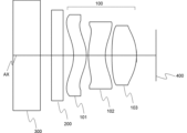
- FIG. 2 is a schematic cross-sectional view showing an optical system when the attachment lens of the present embodiment is used.
- FIG. FIG. 11 is a diagram showing surfaces R1 to R11 and thicknesses (distances) d1 to d10 in a numerical example.
- the attachment lens 100 includes, from the observation object side, a first lens 101 having a positive refractive power, a second lens 102 having a negative refractive power, and a third lens 103 having a positive refractive power.
- Fig. 1 shows an example in which the attachment lens 100 is attached to an imaging lens (the arrangement surface of the imaging lens is indicated by 400 in Fig. 1) that observes an observation object arranged on a sample stage 300 via a flat optical element 200.
- the optical axes AX of the attachment lens 100, the flat optical element 200, and the imaging lens are arranged so as to substantially coincide with the observation site of the observation object.
- the observation object is arranged on the surface of the sample stage 300 on the attachment lens 100 side or on the opposite side.
- Both surfaces of the first lens 101, the second lens 102, and the third lens 103 are aspheric.
- the attachment lens 100 satisfies the following expressions (1), (2), (3), (4), (5), and (6).
- the Abbe number is a value vd defined by the following formula using the refractive index nd for the Fraunhofer d line (587.56 nm), the refractive index nF for the F line (486.1 nm), and the refractive index nC for the C line (656.3 nm).
- ⁇ d ( nd ⁇ 1)/(n F ⁇ n C )
- a lens when a lens has positive refractive power, it means that the power of the lens for the d-line, i.e., the reciprocal of the focal length of the lens for the d-line, is positive, and when a lens has negative refractive power, it means that the power of the lens for the d-line, i.e., the reciprocal of the focal length of the lens for the d-line, is negative.
- the above formulas (1) and (4) define the ratio of the focal length of the first lens 101 and the focal length of the second lens 102 to the total focal length of the attachment lens 100, respectively.
- the ratio of the focal length of the third lens 103 to the total focal length of the attachment lens 100 will be described later, but it is sufficient to adjust the attachment lens 100 so that the desired total focal length f is obtained within a range that satisfies the above formulas (1) and (4).
- f1/f may be 4.33 or more, 4.34 or more, 4.51 or more, 4.62 or more, or 4.90 or more.
- f1/f may be 4.94 or less, 4.63 or less, 4.52 or less, or 4.35 or less.
- f2/f may be -3.18 or more, -3.05 or more, -3.01 or more, -3.00 or more, -2.88 or more, or -2.76 or more.
- f2/f may be -2.80 or less, -2.87 or less, -3.00 or less, or -3.17 or less.
- f, f1, and f2 are not particularly limited, since they can be adjusted as appropriate by changing the size of the optical system, that is, by scaling, while maintaining the relationship between the components of the attachment lens 100.
- f may be, for example, 1.10 mm or more and 10.0 mm or less, 1.20 mm or more and 5.00 mm or less, or 1.30 mm or more and 2.00 mm or less.
- f1 and f2 are designed to satisfy the above formulas (1) and (4), respectively.
- the magnification ratio of the attachment lens means the ratio of the size of an image when the attachment lens is attached to the size of an image when the attachment lens is not attached.
- the magnification ratio ⁇ is determined according to the focal length f 400 of the imaging lens, the focal length f of the attachment lens, the distance between the imaging lens and the attachment lens, etc.
- the magnification ratio ⁇ of the attachment lens 100 is preferably greater than 1.00, more preferably greater than 1.10, and even more preferably greater than 1.20.
- the focal length f of the attachment lens 100 may be appropriately adjusted so that ⁇ falls within the above range depending on the focal length f 400 of the imaging lens, etc.
- the above formulas (2) and (5) define the values of the power ratio to the refractive index of each lens in the first lens 101 and the second lens 102 normalized by the power (1/f) of the attachment lens 100, respectively.
- the sum of the power ratio to the refractive index of each lens approaches 0, the flatness of the image surface of the entire optical system is improved, that is, the image curvature is suppressed.
- the sum of the power ratio to the refractive index of each lens, or the value obtained by normalizing the sum by the power of the entire optical system, is also called the Petzval sum.
- the Petzval sum in the attachment lens 100 can be brought close to 0 by appropriately adjusting the value of the power ratio to the refractive index of the third lens 103 normalized by the power (1/f) of the attachment lens 100, and the deterioration of the flatness of the image surface of the attachment lens 100 can be suppressed.
- ⁇ 1/n1 may be within the range of formula (2) above, 0.130 or more, 0.140 or more, 0.144 or more, or 0.150 or more. Also, ⁇ 1/n1 may be within the range of formula (2) above, 0.155 or less, 0.145 or less, 0.142 or less, 0.140 or less, or 0.135 or less.
- ⁇ 2/n2 may be -0.230 or more, -0.220 or more, -0.210 or more, -0.205 or more, or -0.190 or more within the range of formula (5) above. Also, ⁇ 2/n2 may be -0.180 or less, -0.190 or less, -0.200 or less, or -0.210 or less within the range of formula (5) above.
- n1 is not particularly limited as long as ⁇ 1/n1 satisfies the above formula (2), but may be, for example, 1.20 or more and 2.00 or less, preferably 1.20 or more and 1.80 or less, more preferably 1.40 or more and 1.70 or less, and even more preferably 1.45 or more and 1.60 or less.
- n2 is not particularly limited as long as ⁇ 2/n2 satisfies the above formula (5), but may be, for example, 1.30 or more and 2.10 or less, preferably 1.40 or more and 1.90 or less, more preferably 1.50 or more and 1.80 or less, and even more preferably 1.55 or more and 1.75 or less.
- n1 and n2 are not particularly limited, but it is preferable that n2 is larger, and it is more preferable that n2 is 0.05 or more or 0.10 or more larger than n1.
- the upper limit of the difference between n2 and n1 is not particularly limited, and may be, for example, 0.50, 0.40, 0.30, or 0.20.
- the above formulas (3) and (6) define the ratio of power to Abbe number of each lens in the first lens 101 and the second lens 102, respectively, normalized by the power (1/f) of the attachment lens 100.
- the occurrence of chromatic aberration in the entire optical system can be suppressed.
- the attachment lens 100 since ⁇ 1/ ⁇ 1 and ⁇ 2/ ⁇ 2 are defined by the above formulas (3) and (6), respectively, by appropriately adjusting the value of the power ratio to Abbe number of the third lens 103 normalized by the power (1/f) of the attachment lens 100, the sum in the attachment lens 100 can be brought close to 0, and chromatic aberration in the attachment lens 100 can be reduced.
- ⁇ 1/ ⁇ 1 may be 0.0035 or more, 0.0038 or more, 0.0039 or more, or 0.0040 or more within the range of formula (3) above. Also, ⁇ 1/ ⁇ 1 may be 0.0045 or less, 0.0042 or less, 0.0040 or less, or 0.0039 or less within the range of formula (3) above.
- ⁇ 2/ ⁇ 2 may be -0.0190 or more, -0.0185 or more, -0.0170 or more, -0.0160 or more, or -0.0150 or more within the range of the above formula (6). Also, ⁇ 2/ ⁇ 2 may be -0.0130 or less, -0.0140 or less, -0.0150 or less, or -0.0160 or less within the range of the above formula (6).
- v1 is not particularly limited as long as ⁇ 1/v1 satisfies the above formula (3), but may be, for example, 20 or more and 100 or less, preferably 30 or more and 90 or less, and more preferably 40 or more and 70 or less.
- v2 is not particularly limited as long as ⁇ 2/v2 satisfies the above formula (6), but may be, for example, 5.0 or more and 80 or less, preferably 10 or more and 60 or less, and more preferably 15 or more and 40 or less.
- the magnitude relationship between v1 and v2 is not particularly limited, but it is preferable that v1 is larger, and it is more preferable that v1 is 10 or more or 20 or more larger than v2.
- the upper limit of the difference between v1 and v2 is not particularly limited, and may be, for example, 100, 80, 60, 50, or 40.
- the attachment lens 100 further satisfies the following expressions (7) and (8).
- P in the above formula (7) is a value corresponding to the Petzval sum.
- the first lens 101, the second lens 102, and the third lens 103 are aspheric lenses, so if the first lens 101 and the second lens respectively satisfy the above formulas (2) and (5), a high level of flatness can be achieved for the entire optical system. If P satisfies the above formula (7), a higher level of flatness can be achieved for the entire optical system.
- P may be 0.050 or more, 0.100 or more, 0.200 or more, 0.300 or more, or 0.400 or more within the range of formula (7) above.
- P is preferably 0.500 or less, more preferably 0.490 or less, and even more preferably 0.482 or less within the range of formula (7) above.
- Q in the above formula (8) is a value that mainly relates to the chromatic aberration of the attachment lens 100.
- the first lens 101, the second lens 102, and the third lens 103 are aspheric lenses, so if the first lens 101 and the second lens respectively satisfy the above formulas (3) and (6), the occurrence of chromatic aberration can be suppressed in the entire optical system.
- Q satisfy the above formula (8) the occurrence of chromatic aberration can be further reduced in the entire optical system.
- Q is within the range of the above formula (8) and is preferably -0.0040 or more, more preferably -0.0030 or more, even more preferably -0.0010 or more, and even more preferably 0.0000 or more.
- Q is within the range of the above formula (8) and is preferably 0.0042 or less or 0.0040 or less.
- Q may be 0.0038 or less, or 0.0035 or less.
- the attachment lens 100 may satisfy the following formulas (2A), (3A), (5A), (6A), (7A), and (8A) instead of the above formulas (2), (3), (5), (6), (7), and (8).
- 1/f1n1 may be within the range of formula (2A) above, 0.090 or more, 0.094 or more, 0.095 or more, or 0.098 or more. Also, 1/f1n1 may be within the range of formula (2A) above, 0.105 or less, 0.98 or less, 0.095 or less, 0.093 or less, or 0.090 or less.
- 1/f1 ⁇ 1 may be 0.0023 or more, 0.0025 or more, 0.0026 or more, or 0.0027 or more within the range of formula (3A) above. Also, 1/f1 ⁇ 1 may be 0.0030 or less, 0.0028 or less, 0.0026 or less, or 0.0025 or less within the range of formula (3A) above.
- 1/f2n2 may be -0.150 or more, -0.142 or more, -0.140 or more, -0.130 or more, or -0.127 or more within the range of formula (5A) above. Also, 1/f2n2 may be -0.120 or less, -0.125 or less, -0.135 or less, or -0.140 or less within the range of formula (5A) above.
- 1/f2 ⁇ 2 may be -0.0125 or more, -0.0110 or more, -0.0105 or more, or -0.0100 or more within the range of formula (6A) above. Also, 1/f2 ⁇ 2 may be -0.0085 or less, -0.0090 or less, -0.0100 or less, or -0.0105 or less within the range of formula (6A) above.
- P' and Q' are values obtained by dividing P and Q by f, respectively.
- P' may be 0.030 or more, 0.070 or more, 0.130 or more, 0.200 or more, or 0.250 or more.
- P' is preferably 0.340 or less, more preferably 0.330 or less, and even more preferably 0.320 or less.
- Q' is preferably -0.0028 or more, more preferably -0.0020 or more, even more preferably -0.0010 or more, and even more preferably 0.0000 or more.
- Q' is preferably 0.0029 or less or 0.0028 or less.
- Q' may be 0.0025 or less, or 0.0023 or less.
- the attachment lens 100 further satisfies the following formulas (9), (10), and (11). It is preferable that the attachment lens 100 satisfies the following formulas (9), (10), and (11) in addition to the above formulas (1) to (6), and it is even more preferable that the attachment lens 100 satisfies the following formulas (9), (10), and (11) in addition to the above formulas (1) to (8).
- the above formulas (9) to (11) define the characteristics of the third lens 103. Because the first lens 101 and the second lens 102 of the attachment lens 100 satisfy the above formulas (1) to (6), the overall optical performance does not deteriorate even when the attachment lens 100 is attached to an existing imaging lens, and minute objects can be observed with high resolution. By appropriately adjusting the characteristics of the third lens 103, the desired characteristics can be realized in the attachment lens 100, but by having the third lens 103 satisfy the above formulas (9) to (11), deterioration of the flatness of the image surface of the entire optical system including the imaging lens and the attachment lens, and the occurrence of chromatic aberration can be further suppressed.
- the above formula (9) defines the ratio of the focal length of the third lens 103 to the total focal length of the attachment lens 100.
- f3/f may be 1.15 or more, 1.20 or more, or 1.24 or more within the range of the above formula (9). Also, f3/f may be 1.35 or less, 1.30 or less, or 1.28 or less within the range of the above formula (9).
- the value of f3 is not particularly limited, as it can be adjusted appropriately by scaling the attachment lens 100.
- the above formula (10) defines the ratio of the power to the refractive index of the third lens 103 normalized by the power (1/f) of the attachment lens 100.
- ⁇ 3/n3 may be within the range of formula (10) above, 0.100 or more, 0.300 or more, 0.400 or more, 0.450 or more, or 0.500 or more. Also, ⁇ 3/n3 may be within the range of formula (10) above, 0.580 or less, 0.550 or less, or 0.530 or less.
- n3 is not particularly limited, but may be, for example, 1.20 or more and 2.00 or less, preferably 1.20 or more and 1.80 or less, more preferably 1.40 or more and 1.70 or less, and even more preferably 1.45 or more and 1.60 or less.
- the magnitude relationship between n1, n2, and n3 is not particularly limited, but n3 is preferably smaller than n2.
- n3 may be the same as n1, or may be in the range of n1 ⁇ 0.10.
- the above formula (11) defines the ratio of the power of the third lens 103 to the Abbe number normalized by the power (1/f) of the attachment lens 100.
- ⁇ 3/ ⁇ 3 may be 0.0050 or more, 0.0100 or more, or 0.0140 or more within the range of formula (11) above. Also, ⁇ 3/ ⁇ 3 may be 0.0190 or less, 0.0180 or less, or 0.0150 or less within the range of formula (11) above.
- v3 is not particularly limited, but may be, for example, 20 or more and 100 or less, preferably 30 or more and 90 or less, and more preferably 40 or more and 70 or less.
- the magnitude relationship between v1, v2, and v3 is not particularly limited, but v3 is preferably larger than v2.
- v3 may be the same as v1, or may be in the range of n1 ⁇ 5.0.
- the attachment lens 100 may satisfy the following expressions (10A) and (11A) instead of the above expressions (10) and (11). (10A) 0.000 ⁇ 1/f3n3 ⁇ 0.400 (11A) 0.0000 ⁇ 1/f3 ⁇ 3 ⁇ 0.0140
- 1/f3n3 may be 0.060 or more, 0.200 or more, 0.250 or more, 0.300 or more, or 0.330 or more within the range of the above formula (10A). Also, 1/f3n3 may be 0.380 or less, 0.370 or less, or 0.360 or less within the range of the above formula (10A).
- 1/f3 ⁇ 3 may be 0.0030 or more, 0.0070 or more, or 0.0090 or more within the range of formula (11A) above. Also, 1/f3 ⁇ 3 may be 0.0130 or less, 0.0120 or less, or 0.0100 or less within the range of formula (11A) above.
- the materials constituting the first lens 101, the second lens 102, and the third lens 103 are not particularly limited, and may be, for example, an inorganic material such as glass, an organic material such as resin, or a composite material that combines an inorganic material and an organic material.
- the first lens 101, the second lens 102, and the third lens 103 are not particularly limited as long as they are made of a material that transmits the wavelength of light used for observation, but it is preferable that they are made of a non-fluorescent material.
- a non-fluorescent material when used as an attachment lens for an analytical device that uses ultraviolet light, for example, it is possible to prevent each lens from generating fluorescence due to the ultraviolet light and the fluorescence from becoming measurement noise.
- the first lens 101, the second lens 102, and the third lens 103 are formed from a non-fluorescent material, they can be suitably used as attachment lenses for an analytical device that uses ultraviolet light.
- the attachment lens 100 preferably satisfies the following formulas (1'), (2'), (3'), (4'), (5'), and (6'), and more preferably satisfies the following formulas (7') and (8'), or the following formulas (9'), (10'), and (11'), and even more preferably satisfies the following formulas (7'), (8'), (9'), (10'), and (11').
- the attachment lens 100 can be suitably used as an attachment lens for an analytical device that uses ultraviolet light, and the deterioration of the flatness of the image surface of the entire optical system including the imaging lens and the attachment lens and the occurrence of chromatic aberration can be further suppressed.
- the attachment lens 100 may satisfy the following formulas (2A'), (3A'), (5A'), (6A'), (7A'), (8A'), (10A') and (11A') instead of the above formulas (2'), (3'), (5'), (6'), (7'), (8'), (10') and (11').
- the values of f1/f, ⁇ 1/n1, ⁇ 1/ ⁇ 1, f2/f, ⁇ 2/n2, ⁇ 2/ ⁇ 2, P, Q, f3/f, ⁇ 3/n3, ⁇ 3/ ⁇ 3, f, n1, n2, n3, ⁇ 1, ⁇ 2, and ⁇ 3 may be within the range of the above formulas (1') to (11') obtained by arbitrarily combining the upper and lower limit values exemplified in the above formulas (1) to (11).
- the values of 1/f1n1, 1/f1v1, 1/f2n2, 1/f2v2, P', Q', 1/f3n3, and 1/f3v3 may be within a range obtained by arbitrarily combining the upper and lower limit values exemplified in the above formulas (2A), (3A), (5A), (6A), (7A), (8A), (10A), and (11A).
- the refractive index, Abbe number, and lens shape of each lens may be limited to a certain extent, and by limiting the numerical ranges of the above formulas (1) to (11) to the ranges of the above formulas (1') to (11') and (2A'), (3A'), (5A'), (6A'), (7A'), (8A'), (10A'), and (11A'), it is possible to further suppress the deterioration of the flatness of the image surface of the entire optical system including the imaging lens and attachment lens, and the occurrence of chromatic aberration.
- the attachment lens 100 is used by being attached to an imaging lens, and an observation target is observed through the attachment lens 100.
- the imaging lens is not particularly limited, and may be, for example, an imaging lens of an information processing terminal such as a smartphone or a tablet, or an imaging lens of a camera or a microscope.
- FIG. 1 shows an example in which a flat optical element 200 is inserted between the object to be observed and the first lens 101 of the attachment lens 100.
- the flat optical element 200 is an optical element having a substantially flat shape, and may be, for example, a protective lens for protecting the attachment lens 100, a wavelength filter for transmitting or blocking a specific wavelength, a polarizing plate, or a retardation plate.
- the attachment lens 100 is composed of three lenses and does not require a large number of lenses, so the overall thickness of the attachment lens tends to be thin. Therefore, even when it is necessary to reduce the focal length f or when it is necessary to narrow the distance between the attachment lens 100 and the object of observation, it is easy to design an optical system in which an optical element other than the attachment lens 100 is inserted between the object of observation.
- the attachment lens 100 can be suitably used in applications where the optical design is difficult, such as inserting another optical element such as the flat optical element 200 between the object of observation and the first lens 101. It goes without saying that the attachment lens 100 can also be suitably used in applications where no other optical element is inserted between the object of observation and the first lens 101.
- the attachment lens 100 may be used, for example, for fluorescence analysis or luminescence analysis.
- the flat optical element 200 may be a wavelength filter that selectively transmits light of a wavelength emitted from a fluorescent substance or a luminescent substance contained in the object of observation.
- the wavelength filter may block light of an excitation light wavelength for the fluorescent substance.
- the attachment lens of this embodiment can be used for purposes other than those described above, so long as it is attached to an imaging lens.
- the attachment lens of this embodiment may be used in a form in which the flat optical element 200 in FIG. 1 is omitted, or another optical element may be inserted between the object to be observed and the first lens 101 in place of or in addition to the flat optical element 200.
- R1 to R10 respectively refer to the first principal surface of the sample stage 300, the second principal surface of the sample stage 300, the first principal surface of the flat optical element 200, the second principal surface of the flat optical element 200, the first principal surface of the first lens 101, the second principal surface of the first lens 101, the first principal surface of the second lens 102, the second principal surface of the second lens 102, the first principal surface of the third lens 103, and the second principal surface of the third lens 103.
- R11 also refers to the position of the imaging lens.
- the object to be observed is placed on surface R1.
- the refractive index and Abbe number of the flat optical element 200 can be obtained from a general commercially available UV cut filter or the like.
- the refractive index and Abbe number of the second lens 102 can be obtained from a commercially available lens or the like.
- An example of such a second lens 102 is Iupizeta manufactured by Mitsubishi Gas Chemical Company, Ltd.
- At least numerical examples 1 and 3 are numerical examples in which all lenses are made of non-fluorescent materials.
- R1, R2, R3, and R4 are flat surfaces.
- R5, R6, R7, R8, R9, and R10 are aspheric surfaces, and each surface is expressed by the following aspheric function.
- the optical axis direction is z
- the direction perpendicular to the optical axis is y
- K is the cone coefficient
- R is the radius of curvature
- a04, a06, a08, a10, a12, a14, and a16 are aspheric coefficients.
- the cone coefficient K in the above formula is set to 0, and the radii of curvature R of the surfaces R5 to R10 are set to the values shown in the table below.
- a negative radius of curvature means that the surface has a convex curvature to the right in FIG.
- the focal length f, effective F-number, and half angle of view ⁇ were the values shown in the table below as the overall characteristics of the attachment lens consisting of the first lens 101, the second lens 102, and the third lens 103. From the above, it was found that in each numerical example, even when attached to an existing imaging lens, the overall optical performance is not deteriorated, and it is possible to observe fine objects with high resolution.
- the optical system comprises, from the object side, a first lens having a positive refractive power, a second lens having a negative refractive power, and a third lens having a positive refractive power, Both surfaces of the first lens, the second lens, and the third lens are aspheric, The following formulas (1), (2), (3), (4), (5), and (6) are satisfied. Attachment lens.
- 100 attachment lens
- 101 first lens
- 102 second lens
- 103 third lens
- 200 flat optical element
- 300 sample stage
- 400 imaging lens placement surface
Landscapes
- Physics & Mathematics (AREA)
- General Physics & Mathematics (AREA)
- Optics & Photonics (AREA)
- Chemical & Material Sciences (AREA)
- Analytical Chemistry (AREA)
- Lenses (AREA)
Priority Applications (3)
| Application Number | Priority Date | Filing Date | Title |
|---|---|---|---|
| EP24780113.7A EP4692888A1 (en) | 2023-03-27 | 2024-03-25 | Attachment lens |
| JP2025510810A JPWO2024203995A1 (cg-RX-API-DMAC7.html) | 2023-03-27 | 2024-03-25 | |
| CN202480021132.4A CN120917360A (zh) | 2023-03-27 | 2024-03-25 | 附接透镜 |
Applications Claiming Priority (2)
| Application Number | Priority Date | Filing Date | Title |
|---|---|---|---|
| JP2023050146 | 2023-03-27 | ||
| JP2023-050146 | 2023-03-27 |
Publications (1)
| Publication Number | Publication Date |
|---|---|
| WO2024203995A1 true WO2024203995A1 (ja) | 2024-10-03 |
Family
ID=92906473
Family Applications (1)
| Application Number | Title | Priority Date | Filing Date |
|---|---|---|---|
| PCT/JP2024/011563 Ceased WO2024203995A1 (ja) | 2023-03-27 | 2024-03-25 | アタッチメントレンズ |
Country Status (4)
| Country | Link |
|---|---|
| EP (1) | EP4692888A1 (cg-RX-API-DMAC7.html) |
| JP (1) | JPWO2024203995A1 (cg-RX-API-DMAC7.html) |
| CN (1) | CN120917360A (cg-RX-API-DMAC7.html) |
| WO (1) | WO2024203995A1 (cg-RX-API-DMAC7.html) |
Citations (7)
| Publication number | Priority date | Publication date | Assignee | Title |
|---|---|---|---|---|
| JPS62231919A (ja) * | 1986-04-02 | 1987-10-12 | Canon Inc | コンバ−タ−レンズ |
| JPH02304513A (ja) * | 1989-05-19 | 1990-12-18 | Canon Inc | コンバーターレンズ |
| JP2001100097A (ja) * | 1999-09-29 | 2001-04-13 | Fuji Photo Optical Co Ltd | 近距離撮影用アタッチメントレンズ |
| JP2001147369A (ja) * | 1999-11-22 | 2001-05-29 | Canon Inc | クローズアップレンズ |
| JP2002214529A (ja) | 2001-01-15 | 2002-07-31 | Sony Corp | 広角コンバージョンレンズ及び撮像装置 |
| JP2017097205A (ja) * | 2015-11-26 | 2017-06-01 | 株式会社ニコン | コンバータレンズ、コンバータレンズを備える撮像装置及びコンバータレンズの製造方法 |
| JP2020144177A (ja) | 2019-03-05 | 2020-09-10 | オリンパス株式会社 | コンバージョンレンズ及びこれを有する撮像装置 |
-
2024
- 2024-03-25 JP JP2025510810A patent/JPWO2024203995A1/ja active Pending
- 2024-03-25 WO PCT/JP2024/011563 patent/WO2024203995A1/ja not_active Ceased
- 2024-03-25 CN CN202480021132.4A patent/CN120917360A/zh active Pending
- 2024-03-25 EP EP24780113.7A patent/EP4692888A1/en active Pending
Patent Citations (7)
| Publication number | Priority date | Publication date | Assignee | Title |
|---|---|---|---|---|
| JPS62231919A (ja) * | 1986-04-02 | 1987-10-12 | Canon Inc | コンバ−タ−レンズ |
| JPH02304513A (ja) * | 1989-05-19 | 1990-12-18 | Canon Inc | コンバーターレンズ |
| JP2001100097A (ja) * | 1999-09-29 | 2001-04-13 | Fuji Photo Optical Co Ltd | 近距離撮影用アタッチメントレンズ |
| JP2001147369A (ja) * | 1999-11-22 | 2001-05-29 | Canon Inc | クローズアップレンズ |
| JP2002214529A (ja) | 2001-01-15 | 2002-07-31 | Sony Corp | 広角コンバージョンレンズ及び撮像装置 |
| JP2017097205A (ja) * | 2015-11-26 | 2017-06-01 | 株式会社ニコン | コンバータレンズ、コンバータレンズを備える撮像装置及びコンバータレンズの製造方法 |
| JP2020144177A (ja) | 2019-03-05 | 2020-09-10 | オリンパス株式会社 | コンバージョンレンズ及びこれを有する撮像装置 |
Non-Patent Citations (1)
| Title |
|---|
| See also references of EP4692888A1 |
Also Published As
| Publication number | Publication date |
|---|---|
| EP4692888A1 (en) | 2026-02-11 |
| CN120917360A (zh) | 2025-11-07 |
| JPWO2024203995A1 (cg-RX-API-DMAC7.html) | 2024-10-03 |
Similar Documents
| Publication | Publication Date | Title |
|---|---|---|
| US10989899B2 (en) | Optical imaging lens | |
| US10823938B2 (en) | Optical imaging lens | |
| US11061204B2 (en) | Optical imaging lens comprising four lens of −+−+ refractive powers | |
| US7460307B2 (en) | Projector lens system | |
| JP6362294B1 (ja) | 撮像レンズ | |
| US20200209524A1 (en) | Optical imaging lens | |
| US11609408B2 (en) | Optical imaging lens | |
| JP6362295B1 (ja) | 撮像レンズ | |
| US20060285227A1 (en) | Optical system and optical apparatus having the same | |
| CN110244433B (zh) | 光学成像系统 | |
| JP2010134416A (ja) | リアフォーカス広角レンズ系及びそれを用いた電子撮像装置 | |
| US7253972B2 (en) | Telephoto lens system | |
| US20220121008A1 (en) | Optical imaging lens | |
| US7843651B2 (en) | Wide-angle lens system | |
| US6580568B2 (en) | Telephoto lens system | |
| JP2016170340A (ja) | 撮像レンズ | |
| US20200326517A1 (en) | Optical imaging lens | |
| JP4738879B2 (ja) | 画像読取用レンズおよび画像読取装置 | |
| JP2006349948A (ja) | 光学系及びそれを有する光学機器 | |
| US20230204914A1 (en) | Optical imaging lens | |
| JP2011076021A (ja) | 広角レンズ、光学機器、および広角レンズの製造方法 | |
| JP5544559B1 (ja) | 撮像光学系 | |
| US20220163771A1 (en) | Optical imaging lens | |
| WO2024203995A1 (ja) | アタッチメントレンズ | |
| JP2016061948A (ja) | 投写用ズームレンズおよび投写型表示装置 |
Legal Events
| Date | Code | Title | Description |
|---|---|---|---|
| 121 | Ep: the epo has been informed by wipo that ep was designated in this application |
Ref document number: 24780113 Country of ref document: EP Kind code of ref document: A1 |
|
| WWE | Wipo information: entry into national phase |
Ref document number: 2025510810 Country of ref document: JP |
|
| WWE | Wipo information: entry into national phase |
Ref document number: 202480021132.4 Country of ref document: CN |
|
| WWE | Wipo information: entry into national phase |
Ref document number: 202517097445 Country of ref document: IN |
|
| WWE | Wipo information: entry into national phase |
Ref document number: 2024780113 Country of ref document: EP |
|
| NENP | Non-entry into the national phase |
Ref country code: DE |
|
| WWP | Wipo information: published in national office |
Ref document number: 202480021132.4 Country of ref document: CN |
|
| ENP | Entry into the national phase |
Ref document number: 2024780113 Country of ref document: EP Effective date: 20251027 |
|
| WWP | Wipo information: published in national office |
Ref document number: 202517097445 Country of ref document: IN |
|
| ENP | Entry into the national phase |
Ref document number: 2024780113 Country of ref document: EP Effective date: 20251027 |
|
| ENP | Entry into the national phase |
Ref document number: 2024780113 Country of ref document: EP Effective date: 20251027 |
|
| ENP | Entry into the national phase |
Ref document number: 2024780113 Country of ref document: EP Effective date: 20251027 |
|
| ENP | Entry into the national phase |
Ref document number: 2024780113 Country of ref document: EP Effective date: 20251027 |
|
| ENP | Entry into the national phase |
Ref document number: 2024780113 Country of ref document: EP Effective date: 20251027 |
|
| ENP | Entry into the national phase |
Ref document number: 2024780113 Country of ref document: EP Effective date: 20251027 |
|
| ENP | Entry into the national phase |
Ref document number: 2024780113 Country of ref document: EP Effective date: 20251027 |
|
| WWP | Wipo information: published in national office |
Ref document number: 2024780113 Country of ref document: EP |