WO2024203959A1 - 還元剤およびガスの製造方法 - Google Patents
還元剤およびガスの製造方法 Download PDFInfo
- Publication number
- WO2024203959A1 WO2024203959A1 PCT/JP2024/011495 JP2024011495W WO2024203959A1 WO 2024203959 A1 WO2024203959 A1 WO 2024203959A1 JP 2024011495 W JP2024011495 W JP 2024011495W WO 2024203959 A1 WO2024203959 A1 WO 2024203959A1
- Authority
- WO
- WIPO (PCT)
- Prior art keywords
- reducing agent
- carbon dioxide
- oxygen carrier
- gas
- ray diffraction
- Prior art date
- Legal status (The legal status is an assumption and is not a legal conclusion. Google has not performed a legal analysis and makes no representation as to the accuracy of the status listed.)
- Ceased
Links
Images


Classifications
-
- B—PERFORMING OPERATIONS; TRANSPORTING
- B01—PHYSICAL OR CHEMICAL PROCESSES OR APPARATUS IN GENERAL
- B01J—CHEMICAL OR PHYSICAL PROCESSES, e.g. CATALYSIS OR COLLOID CHEMISTRY; THEIR RELEVANT APPARATUS
- B01J23/00—Catalysts comprising metals or metal oxides or hydroxides, not provided for in group B01J21/00
- B01J23/10—Catalysts comprising metals or metal oxides or hydroxides, not provided for in group B01J21/00 of rare earths
-
- B—PERFORMING OPERATIONS; TRANSPORTING
- B01—PHYSICAL OR CHEMICAL PROCESSES OR APPARATUS IN GENERAL
- B01J—CHEMICAL OR PHYSICAL PROCESSES, e.g. CATALYSIS OR COLLOID CHEMISTRY; THEIR RELEVANT APPARATUS
- B01J23/00—Catalysts comprising metals or metal oxides or hydroxides, not provided for in group B01J21/00
- B01J23/70—Catalysts comprising metals or metal oxides or hydroxides, not provided for in group B01J21/00 of the iron group metals or copper
- B01J23/76—Catalysts comprising metals or metal oxides or hydroxides, not provided for in group B01J21/00 of the iron group metals or copper combined with metals, oxides or hydroxides provided for in groups B01J23/02 - B01J23/36
- B01J23/83—Catalysts comprising metals or metal oxides or hydroxides, not provided for in group B01J21/00 of the iron group metals or copper combined with metals, oxides or hydroxides provided for in groups B01J23/02 - B01J23/36 with rare earths or actinides
-
- B—PERFORMING OPERATIONS; TRANSPORTING
- B01—PHYSICAL OR CHEMICAL PROCESSES OR APPARATUS IN GENERAL
- B01J—CHEMICAL OR PHYSICAL PROCESSES, e.g. CATALYSIS OR COLLOID CHEMISTRY; THEIR RELEVANT APPARATUS
- B01J27/00—Catalysts comprising the elements or compounds of halogens, sulfur, selenium, tellurium, phosphorus or nitrogen; Catalysts comprising carbon compounds
- B01J27/20—Carbon compounds
- B01J27/22—Carbides
- B01J27/224—Silicon carbide
-
- C—CHEMISTRY; METALLURGY
- C01—INORGANIC CHEMISTRY
- C01B—NON-METALLIC ELEMENTS; COMPOUNDS THEREOF; METALLOIDS OR COMPOUNDS THEREOF NOT COVERED BY SUBCLASS C01C
- C01B32/00—Carbon; Compounds thereof
- C01B32/40—Carbon monoxide
-
- C—CHEMISTRY; METALLURGY
- C01—INORGANIC CHEMISTRY
- C01G—COMPOUNDS CONTAINING METALS NOT COVERED BY SUBCLASSES C01D OR C01F
- C01G25/00—Compounds of zirconium
-
- C—CHEMISTRY; METALLURGY
- C01—INORGANIC CHEMISTRY
- C01G—COMPOUNDS CONTAINING METALS NOT COVERED BY SUBCLASSES C01D OR C01F
- C01G49/00—Compounds of iron
Definitions
- the present invention relates to a reducing agent and a method for producing a gas, and more specifically, to a reducing agent that can be used, for example, in a chemical looping method, and a method for producing a gas using such a reducing agent.
- the chemical looping method refers to a method in which the reverse water gas shift reaction is divided into two reactions, a reduction reaction with hydrogen and a production reaction of carbon monoxide from carbon dioxide, and these reactions are bridged by an oxygen carrier (e.g., metal oxide: MO x ) (see the following formula).
- MO x-1 represents a state in which the metal oxide is partially or completely reduced.
- the present invention provides a reducing agent that can be stably used for a long period of time in a reaction at high temperature, and a method for producing a gas using such a reducing agent.
- a reducing agent for reducing carbon dioxide to produce carbon values contains an oxygen carrier having oxygen ion conductivity, which contains at least two metal elements belonging to Group 3 or Group 4 of the periodic table, including lanthanides and actinides.
- the oxygen carrier has an electrical conductivity of 1 ⁇ 10 ⁇ 7 S/cm or more in a pure oxygen atmosphere at a temperature of 700° C., and when X-ray diffraction measurement is performed on the reducing agent in a measurement range of 10° to 90.5°, the full width at half maximum of all peaks observed in the X-ray diffraction profile is less than 1.5°.
- a reducing agent that can be stably used for a long period of time in reactions at high temperatures can be obtained.
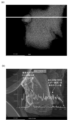
- FIG. 1(a) is an example of an image obtained by STEM-EDS measurement of a reducing agent in which an oxygen carrier and a sub-compound exist independently
- FIG. 1(b) is a graph showing a line profile of the mapping of each element on the white line in FIG. 1(a).
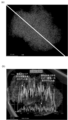
- FIG. 2(a) is an example of an image obtained by STEM-EDS measurement of a reducing agent in which an oxygen carrier and a sub-compound are dissolved
- FIG. 2(b) is a graph showing a line profile of the mapping of each element on the white line in FIG. 2(a).
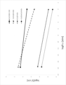
- FIG. 3 is a graph showing an example of the change in electrical conductivity due to the change in oxygen partial pressure.
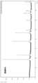
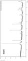
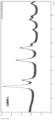
- FIG. 4 is an X-ray diffraction profile of the reducing agent obtained in Example 2.
- FIG. 5 is an X-ray diffraction profile of the reducing agent obtained in Example 4.
- FIG. 6 is an X-ray diffraction profile of the reducing agent obtained in Example 5.
- FIG. 7 is an X-ray diffraction profile of the reducing agent obtained in Example 6.
- FIG. 8 is an X-ray diffraction profile of the reducing agent obtained in Comparative Example 2.
- the reducing agent of the present embodiment is used when producing a product gas containing carbon monoxide (carbon valuable) by reducing carbon dioxide by contacting a raw material gas containing carbon dioxide with the reducing agent (by making the reducing agent act on the raw material gas) (i.e., it is used in the gas production method of the present embodiment). Furthermore, the reducing agent oxidized by contact with carbon dioxide can be reduced (regenerated) by contacting with a reducing gas containing hydrogen (reducing material).
- the raw material gas and the reducing gas are alternately passed through a reaction tube (reaction vessel) filled with the reducing agent of this embodiment, whereby carbon dioxide is converted to carbon monoxide by the reducing agent, and the reducing agent in an oxidized state is regenerated by the reducing gas.
- the reducing agent of the present embodiment contains an oxygen carrier having oxygen ion conductivity.
- the oxygen carrier is a compound that can cause reversible oxygen deficiency, and loses oxygen element from itself through reduction. When the compound comes into contact with carbon dioxide in an oxygen-deficient state (reduced state), it acts to remove the oxygen element from the carbon dioxide and reduce it.
- the oxygen carrier in this embodiment contains at least two kinds of metal elements belonging to Group 3 or Group 4 of the periodic table, including lanthanides and actinides. In such an oxygen carrier, the crystal lattice is distorted by containing two or more kinds of metal elements, and oxygen element is smoothly transferred between the oxygen carrier and the other substance (e.g., carbon dioxide, hydrogen).
- the conversion efficiency from carbon dioxide to carbon monoxide also referred to as carbon dioxide conversion rate
- the conversion efficiency from hydrogen to water also referred to as hydrogen conversion rate
- the carbon dioxide conversion rate and the hydrogenation rate can be determined by the methods described in the examples.
- the oxygen carrier has an electrical conductivity of 1 ⁇ 10 ⁇ 7 S/cm or more in a pure oxygen atmosphere at a temperature of 700° C.
- a reducing agent containing an oxygen carrier having such electrical conductivity can sufficiently increase the migration speed of oxygen ions in the oxygen carrier, so that oxygen elements are efficiently released by contact with a reducing gas, oxygen vacancies are smoothly induced, and the induced oxygen vacancies facilitate the deprivation of oxygen elements from carbon dioxide.
- the electrical conductivity in a pure oxygen atmosphere at a temperature of 700° C. may be 1 ⁇ 10 ⁇ 1 S/cm or less, or may be 1 ⁇ 10 ⁇ 2 S/cm or less.
- under a pure oxygen atmosphere refers to a condition in which the oxygen concentration is 99% by volume or more.
- the full width at half maximum of all peaks observed in the X-ray diffraction profile is less than 1.5°.
- the full width at half maximum of all peaks may be less than 1.5°, but is preferably 1.25° or less, and more preferably 1° or less.
- the full width at half maximum of the peak is preferably 0.1° or more, and more preferably 0.5° or more.
- the reducing agent to be measured by X-ray diffraction can be accurately measured if it has a mass of about 50 mg.
- the timing for measuring the electrical conductivity and the X-ray diffraction was both before the reducing agent was used in the reaction with the gas.
- the reducing agent of the present embodiment preferably further contains an element belonging to Groups 6 to 14 of the periodic table.
- the element belonging to Groups 6 to 14 of the periodic table may be, for example, indium (In), tin (Sn), technetium (Tc), silver (Ag), or the like, or may be an element exemplified below.
- the elements belonging to Groups 6 to 14 of the periodic table more preferably include elements belonging to Groups 8 to 12 of the periodic table, and more preferably include iron (Fe), nickel (Ni), copper (Cu), zinc (Zn), gallium (Ga), and silicon (Si). These elements may be used alone or in combination of two or more.
- the electrical conductivity of the oxygen carrier in a pure oxygen atmosphere at a temperature of 700° C.
- ⁇ B/ ⁇ A is ⁇ A [S/cm] and the electrical conductivity in an argon gas atmosphere containing 1% by volume of carbon monoxide is ⁇ B [S/cm], it is preferable that ⁇ B/ ⁇ A is less than 85.
- ⁇ B/ ⁇ A may be less than 85, but is preferably 80 or less, and more preferably 60 or less.
- the ratio ⁇ B/ ⁇ A may be 10 or more, or 20 or more.
- the reducing agent of the present embodiment preferably contains an element belonging to Groups 6 to 14 of the periodic table as a sub-compound containing the element.
- the secondary compounds include oxides, nitrides, oxynitrides, carbides, etc.
- the secondary compounds include NiO, Fe 2 O 3 , SiC, etc.
- the oxygen carrier and the sub-compound are observed individually, as shown in FIG. 1, and it is preferable that the sub-compound is in the form of particles and in contact with the oxygen carrier.
- This makes it possible to sufficiently increase the reactivity between the oxygen element and the hydrogen element in the crystal lattice of the oxygen carrier. As a result, it is possible to further improve the carbon dioxide conversion rate and the hydrogen conversion rate of the reducing agent.
- the oxygen carrier and the sub-compound are in a solid solution, they cannot be observed individually, as shown in FIG.
- the peaks derived from the oxygen carrier and the peaks derived from the sub-compounds observed in the X-ray diffraction profile are preferably shifted by less than 0.3° in 2 ⁇ with respect to the peaks observed in the X-ray diffraction profile when X-ray diffraction measurement is performed on the oxygen carrier alone and the sub-compound alone, respectively.
- the amount of this shift is more preferably 0.25° or less, even more preferably 0.2° or less, and particularly preferably 0.15° or less.
- the amount of shift may be 0.05° or more, or may be 0.1° or more.
- the average particle size of the sub-compound particles is preferably 1 nm to 10 ⁇ m, more preferably 3 nm to 8 ⁇ m, and even more preferably 5 nm to 6 ⁇ m. This increases the area of the interface formed between the sub-compound particles and the oxygen carrier, allowing the hydrogen element activated by the sub-compound to move more smoothly through the oxygen carrier. This allows the reactivity between the oxygen element and the hydrogen element in the crystal lattice of the oxygen carrier to be sufficiently increased.
- the average particle size of the particles can be determined by acquiring volume-based particle size distribution data using a laser diffraction/scattering type particle size distribution measuring device (e.g., "Partica LA-960" manufactured by Horiba, Ltd.) and processing the data. The measurement is usually performed in a wet manner.
- the crystal structure of the oxygen carrier is stabilized and the heat resistance temperature is increased by sufficiently dissolving each metal element in the oxygen carrier.
- the reducing agent of the present embodiment can be used even at high temperatures exceeding 650° C.
- the metal elements constituting the oxygen carrier are alloyed and tend to form a stable crystal structure, so that the initial activity is likely to be maintained even if the oxidation-reduction of the reducing agent is repeated.
- the packing density of the reducing agent is preferably 4 g/mL or less, more preferably 0.5 g/mL to 3 g/mL or less, and even more preferably 1 g/mL to 2.5 g/mL or less. If the packing density is too low, the gas passage speed becomes too fast, and the time during which the reducing agent is in contact with the raw material gas and the reducing gas decreases. As a result, the carbon dioxide conversion rate and hydrogen conversion rate by the reducing agent tend to decrease. On the other hand, if the packing density is too high, the gas passage speed becomes too slow, making it difficult for the reaction to proceed and requiring a long time to produce the product gas.
- the pore volume of the reducing agent is preferably 0.1 cm 3 /g or more, more preferably 1 cm 3 /g or more and 30 cm 3 /g or less, and even more preferably 5 cm 3 /g or more and 20 cm 3 /g or less. If the pore volume is too small, it becomes difficult for the raw material gas and the reducing gas to penetrate into the inside of the reducing agent. As a result, the contact area between the reducing agent and the raw material gas and the reducing gas decreases, and the carbon dioxide conversion rate and the hydrogen conversion rate by the reducing agent tend to decrease. On the other hand, even if the pore volume is increased beyond the upper limit, no further increase in effect can be expected, and depending on the type of reducing agent, the mechanical strength tends to decrease.
- the shape of the reducing agent is not particularly limited, but is preferably, for example, granular, since the packing density of the reducing agent can be easily adjusted to the above range if the reducing agent is granular.
- granular is a concept including powder, particle, lump, pellet, etc., and the form may be any of spherical, plate-like, polygonal, crushed, columnar, needle-like, and scale-like.
- the average particle size of the reducing agent is preferably 1 ⁇ m or more and 5 mm or less, more preferably 10 ⁇ m or more and 1 mm or less, and even more preferably 20 ⁇ m or more and 0.5 mm or less. If the reducing agent has such an average particle size, it is easy to adjust the packing density to the above range.
- the average particle size means the average particle size of 200 arbitrary reducing agents in one visual field observed by an electron microscope.
- the "particle size” means the maximum length of the distance between two points on the contour line of the reducing agent.
- the maximum length of the distance between two points on the contour line of the end face is taken as the "particle size”.
- the average particle size means the average particle size of the secondary particles.
- the BET specific surface area of the reducing agent is preferably 1 m2 /g or more and 500 m2 /g or less, more preferably 3 m2 /g or more and 450 m2 /g or less, and even more preferably 5 m2 /g or more and 400 m2 /g or less.
- the BET specific surface area can be determined by a low-temperature gas adsorption method using a dynamic constant pressure method in accordance with the BET method (preferably the BET multipoint method).
- the oxygen capacity of the reducing agent can be maintained at a high level over a wide range from low temperature (about 400° C.) to high temperature (about 850° C.)
- the reducing agent of this embodiment can efficiently convert carbon dioxide to carbon monoxide over a wide temperature range, and can be efficiently reduced by a reducing gas containing hydrogen.
- the oxygen capacity of the oxygen carrier contained in the reducing agent at 400° C. is preferably 0.1% by mass or more and 40% by mass or less, and more preferably 0.5% by mass or more and 30% by mass or less.
- the oxygen capacity of the oxygen carrier contained in the reducing agent at low temperatures is within the above range, it means that the oxygen capacity is sufficiently high even at temperatures during actual operation (temperatures exceeding 650° C.), and it can be said that the reducing agent has extremely high carbon dioxide conversion rates and hydrogen conversion rates.
- the method for producing the reducing agent is not particularly limited, but examples thereof include the sol-gel method, coprecipitation method, solid phase method, and hydrothermal synthesis method.
- the reducing agent can be produced as follows. First, a salt of a metal element constituting the reducing agent is dissolved in water to prepare an aqueous solution. Next, this aqueous solution is gelled, and then dried and baked. That is, the reducing agent of this embodiment can be produced easily and reliably by the so-called sol-gel method.
- the aqueous solution may be prepared by using, for example, acidic water adjusted to be acidic with citric acid, acetic acid, malic acid, tartaric acid, hydrochloric acid, nitric acid, or a mixture thereof.
- Examples of the salt of a metal element include nitrates, sulfates, chlorides, hydroxides, carbonates, and compounds thereof, among which nitrates are preferred. Furthermore, hydrates of the salt of a metal element may be used as needed.
- the gel is dried at a temperature of preferably 20° C. to 200° C., more preferably 50° C. to 150° C., for a time of preferably 0.5 hours to 20 hours, more preferably 1 hour to 15 hours. By drying in this manner, the gel can be dried uniformly.
- the gel is preferably fired at a temperature of 300° C. to 1200° C., more preferably 700° C. to 1000° C., for a time of 1 hour to 24 hours, more preferably 1.5 hours to 20 hours.
- the gel is preferably converted into an oxide by firing, but can be easily converted into a reducing agent by firing under the above firing conditions. In addition, firing under the above firing conditions can prevent excessive particle growth of the reducing agent. Until the above-mentioned firing temperature is reached, the temperature is increased at a rate of 1° C./min to 20° C./min, preferably 2° C./min to 10° C./min, which can promote the growth of the reducing agent particles and prevent the cracking of the crystals (particles).
- the reducing agent can also be produced as follows. First, oxides containing the respective metal elements constituting the reducing agent are mixed and pulverized. For pulverization, for example, a ball mill, a bead mill, a jet mill, a hammer mill, a rod mill, etc. can be used. In addition, this pulverization may be performed by either a dry method or a wet method. Next, the crushed aggregate is crushed and then calcined at a temperature of preferably 300° C. to 1200° C., more preferably 700° C. to 1000° C., for a time of preferably 1 hour to 24 hours, more preferably 1.5 hours to 20 hours.
- the reducing agent containing the secondary compound may be produced by adding the secondary compound to the aqueous solution or by mixing the secondary compound with the oxide, with the former being preferred.
- the reducing agent of the present embodiment can be used in, for example, a chemical looping method as described above.
- the reducing agent of the present embodiment can be used in an application for reducing carbon dioxide through contact to generate carbon monoxide (carbon value) as described above. More specifically, it is preferable to carry out a reduction reaction of carbon dioxide and a reduction reaction of a reducing agent, and it is preferable to use the reducing agent so as to circulate between the reduction reaction of carbon dioxide and the reduction reaction of the reducing agent. Note that in the reduction reaction of the reducing agent, a reducing gas containing other reducing substances is used.
- the reducing agent of this embodiment is preferably used in the so-called reverse water gas shift reaction.
- the reverse water gas shift reaction is a reaction that produces carbon monoxide and water from carbon dioxide and hydrogen.
- the reverse water gas shift reaction is carried out separately into a reduction reaction of the reducing agent (first process) and a reduction reaction of carbon dioxide (second process), with the reduction reaction of the reducing agent being the reaction shown in the following formula (A) and the reduction reaction of carbon dioxide being the reaction shown in the following formula (B).
- x is usually 2. That is, in the reduction reaction of the reducing agent, hydrogen, which is a type of reducing substance, is oxidized to produce water, and in the reduction reaction of carbon dioxide, carbon dioxide is reduced to produce carbon monoxide, which is a type of carbon valuable.
- the reaction temperature in the reduction reaction of the reducing agent may be any temperature at which the reduction reaction can proceed, but is preferably a temperature higher than 650° C., more preferably 700° C. or higher, even more preferably 750° C. or higher, and particularly preferably 800° C. or higher. Within this temperature range, the reduction reaction of the reducing agent can proceed efficiently.
- the upper limit of the reaction temperature is preferably 1050° C. or less, more preferably 1000° C. or less, even more preferably 950° C. or less, particularly preferably 900° C. or less, and most preferably 850° C. or less. By setting the upper limit of the reaction temperature in the above range, it is possible to improve economic efficiency.
- the lower limit and the upper limit can be combined in any manner to define the range of the reaction temperature.
- the amount of hydrogen (reducing gas) to be brought into contact with the reducing agent in an oxidized state is preferably 1 mmol to 50 mmol per 1 g of the reducing agent, more preferably 2.5 mmol to 35 mmol, and even more preferably 5 mmol to 20 mmol.
- the reducing agent of this embodiment has a high hydrogen utilization rate because oxygen elements can be smoothly introduced and removed. Therefore, the reducing agent of this embodiment is sufficiently reduced (regenerated) with a small amount of hydrogen. This contributes to reducing the energy required for hydrogen production, and thus also to reducing carbon dioxide generated when obtaining energy.
- the hydrogen utilization rate (%) is a value expressed as a percentage of the amount (number of moles) of carbon monoxide produced relative to the amount (number of moles) of hydrogen introduced into contact with 1 g of reducing agent.
- the reaction temperature in the reduction reaction of carbon dioxide is preferably a temperature exceeding 650° C., more preferably 700° C. or higher, even more preferably 750° C. or higher, and particularly preferably 800° C. or higher. Within this temperature range, the reduction reaction of carbon dioxide can proceed efficiently.
- the upper limit of the reaction temperature is preferably 1050° C. or less, more preferably 1000° C. or less, even more preferably 950° C. or less, particularly preferably 900° C. or less, and most preferably 850° C. or less.
- the reducing agent can perform the reduction reaction of carbon dioxide to carbon monoxide with high efficiency even at low temperatures, so that the reduction reaction of carbon dioxide can be set at a relatively low temperature. Furthermore, by setting the upper limit of the reaction temperature in the above range, not only can waste heat be easily utilized, but also further economic efficiency can be improved.
- the lower limit and the upper limit can be combined in any manner to define the range of the reaction temperature.
- the amount of carbon dioxide brought into contact with the reducing agent is preferably 1 mmol to 50 mmol per 1 g of the reducing agent, more preferably 2.5 mmol to 30 mmol, and even more preferably 5 mmol to 20 mmol.
- the reducing agent of this embodiment allows smooth inflow and outflow of oxygen elements. Therefore, the reducing agent of this embodiment has a high carbon dioxide conversion rate (hence, a large amount of carbon monoxide is produced), and from this viewpoint, it also contributes to the reduction of carbon dioxide.
- the reducing agent can be regenerated with a small amount of hydrogen.
- the amount of carbon monoxide produced in the reducing agent of this embodiment is preferably about 0.3 mmol or more and 1 mmol or less per 1 g of the reducing agent.
- the reduction product (carbon valuable product) obtained by the reduction reaction of carbon dioxide contains carbon monoxide, but may contain other substances other than carbon monoxide, or may be a mixture of carbon monoxide and other substances.
- a specific example of the other substances is methane.
- the reduction products such as carbon monoxide obtained by the reduction reaction of carbon dioxide are further converted into organic substances by microbial fermentation or the like. Examples of microbial fermentation include anaerobic fermentation. Examples of the obtained organic substances include methanol, ethanol, acetic acid, butanol, derivatives thereof, or mixtures thereof, and compounds of C5 or more such as isoprene.
- the reduced products such as carbon monoxide may be converted by metal oxides, etc., into C1 to C20 compounds including hydrocarbons and alcohols that are conventionally synthesized by petrochemistry.
- Specific compounds that can be obtained include methane, ethane, propylene, methanol, ethanol, propanol, acetaldehyde, diethyl ether, acetic acid, butyric acid, diethyl carbonate, butadiene, etc.
- the reducing agent of the present embodiment preferably has the following properties. That is, when a reducing agent is filled to a height of 40 cm in a stainless steel reaction tube having an inner diameter of 8 mm and a pressure gauge disposed in the flow path, and nitrogen gas having a concentration of 100% by volume is passed through at 30 mL/min, the pressure increase over 10 minutes is preferably 0.03 MPaG or less, and more preferably 0.01 MPaG or less.
- a reducing agent exhibiting such characteristics can be determined to have a packing density and a pore volume that satisfy the above ranges, and can sufficiently increase the carbon dioxide conversion rate and the hydrogen conversion rate.
- a reducing agent that can be stably used for a long period of time in a reaction at high temperature, and a method for producing a gas using this reducing agent.
- the reducing agent of the present embodiment can withstand use at high temperatures, and therefore enables more efficient conversion of carbon dioxide to carbon monoxide (carbon value) through a chemical looping reaction at high temperatures. Furthermore, it may be provided in the following aspects:
- a reducing agent that reduces carbon dioxide to produce carbon values comprising an oxygen carrier having oxygen ion conductivity, the oxygen carrier containing at least two metal elements belonging to Group 3 or Group 4 of the periodic table, including lanthanides and actinides, the oxygen carrier having an electrical conductivity of 1 x 10⁻⁷ S/cm or more in a pure oxygen atmosphere at a temperature of 700°C, and when X-ray diffraction measurement is performed on the reducing agent in a measurement range of 10° to 90.5°, the full width at half maximum of all peaks observed in the X-ray diffraction profile is less than 1.5°.
- the reducing agent described in (1) above further contains an element belonging to Groups 6 to 14 of the periodic table, and the oxygen carrier has an electrical conductivity of ⁇ A [S/cm] in a pure oxygen atmosphere at a temperature of 700°C and an electrical conductivity of ⁇ B [S/cm] in an argon gas atmosphere containing 1% by volume of carbon monoxide, where ⁇ B/ ⁇ A is less than 85.
- the reducing agent according to (2) above further contains an auxiliary compound containing an element belonging to Groups 6 to 14 of the periodic table, and when the reducing agent is subjected to a scanning transmission electron microscope-energy dispersive X-ray spectroscopy (STEM-EDS) measurement, the oxygen carrier and the auxiliary compound are observed separately, and the auxiliary compound is in the form of particles and in contact with the oxygen carrier.
- STEM-EDS scanning transmission electron microscope-energy dispersive X-ray spectroscopy
- the reducing agent contains at least two metal elements belonging to Group 3 or Group 4 of the periodic table, including lanthanides and actinides, and contains an oxygen carrier having oxygen ion conductivity, the oxygen carrier having an electric conductivity of 1 x 10⁻⁷ S/cm or more in a pure oxygen atmosphere at a
- containing a metal element does not only mean that a single metal element is contained, but also that two or more metal elements are in an alloy state, or that the metal element is in a compound state.
- the compound includes various states such as oxides, nitrides, chlorides, sulfides, and salts including nitrates.
- the reducing agent and gas producing method of the present invention may have any other additional configuration compared to the above-mentioned embodiment, may be replaced with any configuration that exhibits a similar function, or some configurations may be omitted.
- a gas containing hydrogen has been described as a representative reducing gas.
- the reducing gas may also be a gas containing at least one selected from hydrocarbons (e.g., methane, ethane, acetylene, etc.) and ammonia as a reducing substance instead of or in addition to hydrogen.
- Example 2 Production of reducing agent (Example 1) First, predetermined amounts of cerium (III) nitrate hexahydrate and zirconium nitrate dihydrate were each weighed out. Next, 6.06 g of citric acid (manufactured by Fujifilm Wako Pure Chemical Industries, Ltd., purity: 99.5%) was weighed and dissolved in 96 mL of deionized water to obtain an aqueous citric acid solution. The precursor (metal nitrate salt) was then added to the aqueous citric acid solution at room temperature while stirring to prepare an aqueous precursor solution. The molar ratio of Ce:Zr in the aqueous precursor solution was 0.9:0.1.
- ethylene glycol manufactured by Fujifilm Wako Pure Chemical Industries, Ltd., purity: 99.5%
- the temperature was maintained at 80° C. with continuous stirring until a viscous gel was formed, after which the gel was transferred to a drying oven.
- the gel was dried at 120° C. for 5 hours.
- the resulting swollen mass of organic and inorganic compounds was pulverized, and the temperature was raised from room temperature to 450° C. at a rate of 8° C./min in an air atmosphere, and then calcined at 450° C. for 4 hours. Thereafter, the temperature was further raised to 950° C. at a rate of 8° C./min, and then calcined at 950° C. for 8 hours.
- the fired mass was mechanically pulverized to obtain the target reducing agent composed of the oxygen carrier alone.
- the reducing agent was in granular form. In order to facilitate filling into the reaction tube or to satisfy the requirement of pressure rise described in the section on [Properties of the Reducing Agent], the reducing agent was compressed into tablets for use in the tests, as necessary.
- Example 2 to 6 and Comparative Examples 1 and 2 A reducing agent composed of an oxygen carrier alone or an oxygen carrier and a sub-compound was produced in the same manner as in Example 1, except for changing the type and amount of the oxygen carrier precursor used and/or adding a sub-compound.
- the sub-compound was added to the precursor aqueous solution in the form of particles.
- the resulting reducing agent was granular.
- the diffractometer was set with a divergence slit at 1/2°, a divergence longitudinal limiting slit at 10 mm, a scattering slit at 2°, and a receiving slit at 0.15 mm.
- the goniometer radius was 145 mm.
- the prepared reducing agent sample was irradiated with X-rays under conditions of a tube voltage of 40 kV and a tube current of 15 mA.
- the measurement was performed by setting the scanning angle of the goniometer to a range of 10° to 90.5°, the scanning speed to 3.5°/min, and the measurement step to 0.01. The measurement was performed in air at room temperature.
- the data obtained without separation of K ⁇ 1 and K ⁇ 2 was analyzed.
- the data was analyzed using software (High Score, manufactured by PANanalytical). If it is difficult to distinguish the baseline, the software may be used to correct it.
- the highest intensity of the diffraction peak was taken as the apex, and the distance between the two points at half the intensity of the maximum peak value was taken as the full width at half maximum.
- STEM-EDS Measurement The reducing agent was ultrasonically dispersed in ethanol, dropped onto a grid, and then dried. Observation and EDS analysis were performed using STEM (mapping ⁇ line profiling). For the line profile, a line was drawn so as to intersect with the interface between the oxygen carrier and the sub-compound observed in the element mapping of the STEM-EDS measurement, and the count number of each element at a certain point on the line was plotted.
- STEM-EDS: EDAX (TEAM) ⁇ Parameters Acceleration voltage: 200 kV
- EDS mapping resolution 256 x 200 Dwell: 200
- Particle size distribution measurement (wet method) The particle size distribution was measured using a laser diffraction/scattering type particle size distribution measuring device ("Partica LA-960" manufactured by Horiba, Ltd.) in a wet flow cell.
- the flow cell was made of synthetic quartz, the light source was a semiconductor laser (650 nm) of 5 mW and an LED (405 nm) of 3 mW, and the detector was a ring-shaped silicon photodiode.
- the measurement was performed at a temperature of 25° C. and a humidity of 20%, on a dispersion obtained by dispersing about 10 mg of the reducing agent in about 180 mL of purified water (pH 6.8 to 7.2).
- the measurement was carried out at least three times, and the median particle diameters obtained by each particle size distribution measurement were averaged to obtain the average particle diameter.
- the electrical conductivity measured in the pure oxygen atmosphere was designated as " ⁇ A", and the electrical conductivity measured in the carbon monoxide-containing atmosphere was designated as " ⁇ B".
- Data was analyzed using software (Microsoft's "Excel").
- the reducing agent consisting only of an oxygen carrier was used as is for the electrical conductivity measurement.
- an oxygen carrier was separately produced in the same manner as described above without adding the secondary compound to the precursor aqueous solution, and this oxygen carrier was used for the electrical conductivity measurement.
- the conversion rate was calculated from the time when the amount of carbon monoxide generated per unit second became 0 mmol or more after the start of flowing carbon dioxide gas (feed gas) until the value of the following formula calculated based on the signal detected by a quadrupole mass spectrometer fell below 80. The average value calculated during this period was defined as the carbon dioxide conversion rate. Note that the region where the amount of carbon monoxide generated was 0 mmol or less was not used in calculating the conversion rate.
- the amount of carbon monoxide produced in each cycle was measured when the carbon monoxide concentration detected by NDIR (non-dispersive infrared) reached 2.0% or more after carbon dioxide gas (raw material gas) was started to flow.
- the carbon monoxide concentration detected by NDIR was recorded every 5.0 seconds, and the amount of carbon monoxide produced was calculated from the carbon monoxide concentration recorded during this period by quadrature by division. Note that the area where the carbon monoxide concentration was less than 2.0% was not used in the calculation of the amount of carbon monoxide produced.
- the full width at half maximum of all peaks observed in the X-ray diffraction profile of the reducing agent obtained in each Example is less than 1.5°.
- the full width at half maximum of at least one peak observed in the X-ray diffraction profile of the reducing agent obtained in each Comparative Example is 1.5° or more.
- the X-ray diffraction profiles of the reducing agents obtained in Examples 2, 4, 5, and 6 and Comparative Example 2 are shown in FIGS. 4 to 8, respectively.
Landscapes
- Chemical & Material Sciences (AREA)
- Organic Chemistry (AREA)
- Inorganic Chemistry (AREA)
- Engineering & Computer Science (AREA)
- Materials Engineering (AREA)
- Chemical Kinetics & Catalysis (AREA)
- Carbon And Carbon Compounds (AREA)
Priority Applications (1)
| Application Number | Priority Date | Filing Date | Title |
|---|---|---|---|
| JP2025510784A JPWO2024203959A1 (cg-RX-API-DMAC7.html) | 2023-03-24 | 2024-03-22 |
Applications Claiming Priority (2)
| Application Number | Priority Date | Filing Date | Title |
|---|---|---|---|
| JP2023047485 | 2023-03-24 | ||
| JP2023-047485 | 2023-03-24 |
Publications (1)
| Publication Number | Publication Date |
|---|---|
| WO2024203959A1 true WO2024203959A1 (ja) | 2024-10-03 |
Family
ID=92905195
Family Applications (1)
| Application Number | Title | Priority Date | Filing Date |
|---|---|---|---|
| PCT/JP2024/011495 Ceased WO2024203959A1 (ja) | 2023-03-24 | 2024-03-22 | 還元剤およびガスの製造方法 |
Country Status (2)
| Country | Link |
|---|---|
| JP (1) | JPWO2024203959A1 (cg-RX-API-DMAC7.html) |
| WO (1) | WO2024203959A1 (cg-RX-API-DMAC7.html) |
Citations (6)
| Publication number | Priority date | Publication date | Assignee | Title |
|---|---|---|---|---|
| WO2012057162A1 (ja) * | 2010-10-26 | 2012-05-03 | 三井金属鉱業株式会社 | 一酸化炭素の製造方法及び製造装置 |
| US20210284540A1 (en) * | 2018-07-18 | 2021-09-16 | University Of Florida Research Foundation, Inc. | Facile co2 sequestration and fuel production from a hydrocarbon |
| WO2021192872A1 (ja) * | 2020-03-25 | 2021-09-30 | 積水化学工業株式会社 | 還元剤およびガスの製造方法 |
| WO2021192871A1 (ja) * | 2020-03-25 | 2021-09-30 | 積水化学工業株式会社 | 還元剤およびガスの製造方法 |
| WO2023167288A1 (ja) * | 2022-03-03 | 2023-09-07 | 積水化学工業株式会社 | 還元剤およびガスの製造方法 |
| WO2023167287A1 (ja) * | 2022-03-03 | 2023-09-07 | 積水化学工業株式会社 | 還元剤およびガスの製造方法 |
-
2024
- 2024-03-22 JP JP2025510784A patent/JPWO2024203959A1/ja active Pending
- 2024-03-22 WO PCT/JP2024/011495 patent/WO2024203959A1/ja not_active Ceased
Patent Citations (6)
| Publication number | Priority date | Publication date | Assignee | Title |
|---|---|---|---|---|
| WO2012057162A1 (ja) * | 2010-10-26 | 2012-05-03 | 三井金属鉱業株式会社 | 一酸化炭素の製造方法及び製造装置 |
| US20210284540A1 (en) * | 2018-07-18 | 2021-09-16 | University Of Florida Research Foundation, Inc. | Facile co2 sequestration and fuel production from a hydrocarbon |
| WO2021192872A1 (ja) * | 2020-03-25 | 2021-09-30 | 積水化学工業株式会社 | 還元剤およびガスの製造方法 |
| WO2021192871A1 (ja) * | 2020-03-25 | 2021-09-30 | 積水化学工業株式会社 | 還元剤およびガスの製造方法 |
| WO2023167288A1 (ja) * | 2022-03-03 | 2023-09-07 | 積水化学工業株式会社 | 還元剤およびガスの製造方法 |
| WO2023167287A1 (ja) * | 2022-03-03 | 2023-09-07 | 積水化学工業株式会社 | 還元剤およびガスの製造方法 |
Also Published As
| Publication number | Publication date |
|---|---|
| JPWO2024203959A1 (cg-RX-API-DMAC7.html) | 2024-10-03 |
Similar Documents
| Publication | Publication Date | Title |
|---|---|---|
| Valderrama et al. | LaNi1-xMnxO3 perovskite-type oxides as catalysts precursors for dry reforming of methane | |
| Toniolo et al. | Structural investigation of LaCoO3 and LaCoCuO3 perovskite-type oxides and the effect of Cu on coke deposition in the partial oxidation of methane | |
| TWI433723B (zh) | Catalyst precursors and catalysts using them | |
| KR101994152B1 (ko) | 탄소 침적의 감소를 위해, 금속이온이 치환된 페로브스카이트 금속산화물 촉매 및 이의 제조 방법, 그리고 이를 이용한 메탄 개질 반응 방법 | |
| KR102129274B1 (ko) | 공융용매를 이용한 금속 복합 산화물의 제조방법 | |
| US20100102278A1 (en) | Low temperature water gas shift catalyst | |
| KR102270807B1 (ko) | 금속산화물을 이용한 이산화탄소 전환 방법 | |
| EP4129920A1 (en) | Reducing agent, and method for producing gas | |
| JP5982189B2 (ja) | 水分解用光触媒 | |
| EP4487949A1 (en) | Reducing agent, and gas production method | |
| Albaladejo-Fuentes et al. | Tailoring the properties of BaTi0. 8Cu0. 2O3 catalyst selecting the synthesis method | |
| Roy et al. | Activating cobalt inverse spinel oxides via Fe substitution for enhanced water splitting reaction | |
| WO2021192872A1 (ja) | 還元剤およびガスの製造方法 | |
| Alkhoori et al. | Exsolved LaNiRuO3 perovskite-based catalysts for CO2 methanation reaction | |
| Strazzolini et al. | Design of Ni-promoted Ca2Fe2O5/modified ceria as oxygen carrier for fast and carbon-resistant chemical-looping steam methane reforming | |
| JP4719181B2 (ja) | 炭化水素改質用触媒 | |
| KR20190067146A (ko) | 탄소 침적을 감소시킬 수 있는, 금속이온이 치환된 페로브스카이트 금속산화물 촉매의 제조 방법 및 이를 이용한 메탄 개질 반응 방법 | |
| Barison et al. | Novel Ru/La0. 75Sr0. 25Cr0. 5Mn0. 5O3-δ catalysts for propane reforming in IT-SOFCs | |
| EP4219403A1 (en) | Oxygen carrier, method for producing oxygen carrier, and method for producing gas | |
| JP2005046808A (ja) | 水素生成触媒 | |
| KR20250097287A (ko) | 페로브스카이트 촉매, 그 제조방법 및 그 응용 | |
| JP2023106808A (ja) | NiAl2O4とγ-Al2O3とZrO2とが複合化した複合酸化物、当該複合酸化物の還元物である活性材料、及び当該活性材料の再生方法 | |
| WO2025063248A1 (ja) | 酸素キャリア、酸素キャリアの製造方法及びガスの製造方法 | |
| JP2006116372A (ja) | 一酸化炭素選択酸化触媒 | |
| Carrillo et al. | Exploring the stability of Fe–Ni alloy nanoparticles exsolved from double-layered perovskites for dry reforming of methane, Catalysts, 2021, 11, 741 |
Legal Events
| Date | Code | Title | Description |
|---|---|---|---|
| 121 | Ep: the epo has been informed by wipo that ep was designated in this application |
Ref document number: 24780077 Country of ref document: EP Kind code of ref document: A1 |
|
| WWE | Wipo information: entry into national phase |
Ref document number: 2025510784 Country of ref document: JP |
|
| NENP | Non-entry into the national phase |
Ref country code: DE |
|
| 122 | Ep: pct application non-entry in european phase |
Ref document number: 24780077 Country of ref document: EP Kind code of ref document: A1 |