WO2024203845A1 - 光拡散装置 - Google Patents
光拡散装置 Download PDFInfo
- Publication number
- WO2024203845A1 WO2024203845A1 PCT/JP2024/011288 JP2024011288W WO2024203845A1 WO 2024203845 A1 WO2024203845 A1 WO 2024203845A1 JP 2024011288 W JP2024011288 W JP 2024011288W WO 2024203845 A1 WO2024203845 A1 WO 2024203845A1
- Authority
- WO
- WIPO (PCT)
- Prior art keywords
- light
- optical fiber
- sheath
- light emitting
- diffusion device
- Prior art date
- Legal status (The legal status is an assumption and is not a legal conclusion. Google has not performed a legal analysis and makes no representation as to the accuracy of the status listed.)
- Ceased
Links
Images







Classifications
-
- A—HUMAN NECESSITIES
- A61—MEDICAL OR VETERINARY SCIENCE; HYGIENE
- A61N—ELECTROTHERAPY; MAGNETOTHERAPY; RADIATION THERAPY; ULTRASOUND THERAPY
- A61N5/00—Radiation therapy
- A61N5/06—Radiation therapy using light
- A61N5/067—Radiation therapy using light using laser light
Definitions
- the present invention relates to a light diffusion device for use in medical equipment.
- a conventional light diffusion device includes an optical fiber consisting of a core located at the radial center and a cladding located on the outer periphery of the core, and that emits laser light incident on the base end BE of the optical fiber from the tip end T of the optical fiber and the outer periphery of the tip side T (see, for example, Patent Document 1).
- the optical fiber of the conventional light diffusion device has a light transmission section that transmits the laser light incident on the base end BE, and a light emission section at the tip side T that emits the laser light transmitted through the light transmission section.
- Light diffusion devices are used in photodynamic therapy (PDT) and photoimmunotherapy (PIT), which are light-based cancer treatments.
- PDT photodynamic therapy
- PIT photoimmunotherapy
- the tip T of an optical fiber is inserted into the human body and laser light is irradiated onto drugs that have been administered to the body and have reached the cancer cells.
- a diffuser irradiates light laterally at the tip T of the optical fiber, but since light is usually irradiated in all circumferential directions, there is a concern that the light may hit healthy cells as well as cancer cells.
- One of the objectives of the present invention is to provide a light diffusion device that can limit the irradiation area while suppressing heat generation at the light emitting section and its vicinity.
- a light diffusing device is a light diffusing device comprising an optical fiber having a core located on a radial center side and a clad located on an outer peripheral side of the core, the light diffusing device diffusing light incident on a base end of the optical fiber and emitting the light from a tip end side of the optical fiber
- the optical fiber is made of plastic and has a light transmitting section that transmits light incident from a base end portion toward a tip end portion, and a light emitting section that emits the light transmitted through the light transmitting section from an outer peripheral surface at the tip side, and the light emitting section is treated to suppress heat generation
- a reflecting member having a light reflectance of 80% or more is provided on an outer peripheral surface of the light emitting portion in a region other than a region that becomes a light emitting port and on a tip surface of the light emitting portion
- the reflective member includes particles having light reflectivity, The particles include barium sulfate.
- a protective member may be provided that covers and seals the reflective member.
- At least a portion of the cladding in the light-emitting portion may be removed.
- a rough surface may be formed on the outer peripheral surface of the light-emitting portion from which the cladding has been removed, and at least one of the surface roughness indices Rp, Rz, and Ra of the outer peripheral surface may be equal to or less than the wavelength of the light emitted from the light-emitting portion.
- the reflecting member extending in the axial direction may be provided in an arc-shaped region of a predetermined central angle ⁇ on the outer peripheral surface of the optical fiber, and the remaining arc-shaped region where the reflecting member is not provided may serve as the light exit port.
- the central angle ⁇ may be 180° or more.
- the optical fiber includes a first sheath that is opaque to light and surrounds at least the light emitting portion of the optical fiber, an opening is provided in a region of the first sheath that can face the light exit port,
- the optical fiber may be rotatable relative to the first sheath in the circumferential direction.
- the optical fiber includes a first sheath that is opaque to light and surrounds at least the light emitting portion of the optical fiber, an opening is provided in a region of the first sheath that can face the light exit port,
- the optical fiber may be movable relative to the first sheath in the axial direction.
- a balloon-type second sheath having optical transparency may be provided on the outside of the first sheath.
- a light diffusion device that can limit the irradiation area while suppressing heat generation at the light emitting portion and its vicinity.
- FIG. 1 is a schematic diagram of a light diffusing device according to a first embodiment which is an exemplary aspect of the present invention.
- 4 is a cross-sectional view taken along a plane including the axis x of the light exit portion of the optical fiber and its vicinity in the light diffusing device according to the first embodiment, and is a cross-sectional view taken along the line BB in FIG. 3.
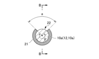
- 3 is a cross-sectional view taken along a plane perpendicular to the axis x of the light emission portion of the optical fiber in the light diffusing device according to the first embodiment, and is a cross-sectional view taken along the line AA in FIG. 2.
- 2 is an enlarged cross-sectional view showing a main part of an optical fiber in the light diffusing device according to the first embodiment.
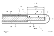
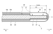
- FIG. 7 is a cross-sectional view taken along a plane including the axis x of the light output portion of an optical fiber and its vicinity in a light diffusion device according to a second embodiment which is an exemplary aspect of the present invention, and is a cross-sectional view taken along the line D-D in FIG. 7 is a cross-sectional view taken along a plane perpendicular to the axis x of a portion of a light emission portion of an optical fiber in a light diffusing device according to a second embodiment, and is a cross-sectional view taken along the CC section in FIG. 6.
- 13 is a perspective view of a light exit portion of an optical fiber in a light diffusing device according to a second embodiment and its vicinity.
- FIG. 7 is a cross-sectional view of the same cross section as FIG. 6 , illustrating an example of a state in which a light emission (irradiation) region in a circumferential direction is narrowed in a light diffusing device according to a second embodiment.
- 6 is a cross-sectional view of the same cross section as FIG. 5 , illustrating an example of a state in which a light emission (irradiation) region in the axial direction is changed in a light diffusing device according to a second embodiment.
- 7 is a cross-sectional view of the same cross section as FIG. 5 , illustrating another example of a state in which a light emission (irradiation) region in the axial direction is changed in the light diffusing device according to the second embodiment.
- FIG. 11 is a cross-sectional view taken along a plane including the axis x of a light exit portion of an optical fiber and its vicinity in a light diffusing device according to a third embodiment which is an exemplary aspect of the present invention.
- FIG. 13 is a perspective view of a light exit portion of an optical fiber in a light diffusing device according to a third embodiment and its vicinity.
- Fig. 1 is a schematic diagram of a light diffusing device 1 according to a first embodiment
- Fig. 2 is a cross-sectional view taken along a plane including a light emitting portion 12 of an optical fiber in the light diffusing device 1 and its vicinity
- Fig. 3 is a cross-sectional view taken along a plane perpendicular to the axis x of the portion of the light emitting portion 12.
- Fig. 2 is a cross-sectional view taken along the B-B section in Fig. 3
- Fig. 3 is a cross-sectional view taken along the A-A section in Fig. 2.
- the base end side B of the optical fiber is indicated by an arrow B
- the tip side T is indicated by an arrow T.
- the light diffusion device 1 of this embodiment is used in photodynamic therapy (PDT) and photoimmunotherapy (PIT), which are cancer treatment methods.
- Photoimmunotherapy in particular is a procedure for treating cancer by administering to the human body a drug consisting of an antibody that binds to cancer cells and a substance that reacts to light, and then irradiating the drug that has bound to the cancer cells with laser light to destroy the cancer cells.
- the light diffusion device 1 is a device that emits light incident on the base end BE of the optical fiber 10 from the tip side T, and a laser oscillator 30 is connected to the base end BE of the base end B of the optical fiber 10 as a light source for generating laser light.
- the laser oscillator 30 has a semiconductor laser, and generates laser light by passing electricity through the semiconductor laser to cause laser oscillation.
- the laser oscillator 30 generates laser light having a wavelength of 500 nm or more and 900 nm or less.
- the optical fiber 10 is made of a plastic (resin) material. As shown in FIG. 3, the optical fiber 10 is a single-core optical fiber that is made up of a core 10a located in the center in the radial direction and a cladding 10b located on the outer periphery of the core 10a.
- the optical fiber 10 has a relative refractive index difference between the core 21 and the cladding 22 of 2% or more and 11% or less.
- the optical fiber 10 has an outer diameter of 500 ⁇ m, an outer diameter of the core 10a of 480 ⁇ m, and a thickness of the cladding 10b of 10 ⁇ m.
- the outer diameter of the cladding 10b of the optical fiber 10 is 102 ⁇ m or more and 1100 ⁇ m or less.
- the outer diameter of the core 10a of the optical fiber 10 is 100 ⁇ m or more and 1000 ⁇ m or less.
- the thickness of the cladding 10b is 1 ⁇ m or more and 50 ⁇ m or less.
- the optical fiber 10 has a light transmission section 11 that transmits the laser light incident from the base end BE toward the tip side T, and a light emission section 12 that causes the laser light transmitted through the light transmission section 11 to exit from the outer circumferential surface by removing the cladding 10b within a predetermined range in the extension direction of the tip side T.
- a reflective member 21 is provided on a portion of the outer peripheral surface of the light emitting portion 12 and on the tip surface. More specifically, as shown in Figure 3, a reflective member 21 extending in the axial x direction is provided in an arc-shaped region of a predetermined central angle ⁇ on the outer peripheral surface of the optical fiber 10. The remaining arc-shaped region a where the reflective member 21 is not provided becomes the light exit port 22.
- the reflective member 21 is a member that blocks light that attempts to exit from the outer peripheral surface of the light emitting portion 12 other than the light exit port 22 in the circumferential direction, and also reflects it to emit it from the light exit port 22.
- the central angle ⁇ that defines the area in which the reflective member 21 is provided is set to, for example, 120°.
- this central angle ⁇ is preferably 180° or more (i.e., the area a that becomes the irradiation range is 180° or less), and more preferably 210° or more (i.e., the area a that becomes the irradiation range is 150° or less).
- the reflective member 21 has a light reflectance of 80% or more, preferably 90% or more, and more preferably 95% or more.
- a reflective member 21 with high light reflectance it is possible to limit the irradiation area and irradiate light with high efficiency while suppressing heat generation at the light emitting section 12 and its vicinity.
- the reflection of light reflectance referred to here includes both regular reflection and diffuse reflection.
- the reflective member 21 be as thin as possible.
- the diameter of the light emitting portion 12 of the light diffusion device 1 (the diameter formed by the optical fiber 10 and the reflective member 21 in the light emitting portion 12; the same applies below) can be reduced, which increases the flexibility of the procedure, such as making it possible to insert the reflective member 21 into a small-diameter needle catheter, pass it through small blood vessels in the body, or access organs through small blood vessels.
- the diameter of the light emitting portion 12 of the light diffusion device 1 is 1 mm or less. By making the diameter of the light emitting portion 12 of the light diffusion device 1 1 mm or less, it can be inserted into a general needle catheter. Also, in the second embodiment described later, a general needle catheter can be processed and used as the first sheath.
- the thickness of the reflective member 21 is preferably 500 nm or less, and more preferably 300 nm or less.
- the reflective member 21 does not have to be layered, and may be formed, for example, in a block shape.
- the material of the reflective member 21 there are no particular restrictions on the material of the reflective member 21 as long as it satisfies the above conditions for light reflectance, but it is preferable for it to contain light-reflective particles, as this allows for a high light reflectance to be achieved even though it is a thin film.
- Particles having light reflectivity that are suitable for use as the material of the reflective member 21 include barium sulfate, titanium oxide, silica, alumina, calcium carbonate, and various other porous bodies (e.g., porous polytetrafluoroethylene (PTFE)).
- barium sulfate, titanium oxide, silica, and alumina are preferred, and barium sulfate is particularly preferred because it has an extremely high light reflectance (approximately 97% to 98%).
- the light-reflective particles can be formed by applying a coating liquid made by mixing an adhesive resin such as polyvinyl alcohol, epoxy resin, or silicone resin with a solvent such as water or alcohol to the area to be coated, and then drying and hardening the coating film to form the reflective member 21.
- a coating liquid made by mixing an adhesive resin such as polyvinyl alcohol, epoxy resin, or silicone resin with a solvent such as water or alcohol
- the area a in the circumferential direction where the reflective member 21 is not provided can be sealed before applying the coating liquid, and the seal can be removed after drying and hardening to form the light exit port 22.
- a protective member (not shown) that covers and seals the reflective member 21 may be provided to prevent the formed layer from falling off.
- a protective member By sealing the reflective member 21 with a protective member, it is possible to prevent the reflective member 21 from falling off, and even if the reflective member 21 is not biocompatible, it can be isolated by a biocompatible protective member.
- the protective member may be sealed so as to cover the entire reflective member 21, or may be sealed with a tube that covers the entire circumference of the optical fiber 10 including the light exit port 22.
- a tubular protective member it is desirable to seal the end of the tip side T and fill the inside with air to seal it.
- the material of the protective member includes nylon, polyamide, PTFE, ethylene-tetrafluoroethylene copolymer (ETFE), polyvinyl chloride, polyvinylidene chloride, urethane resin, and silicone resin, but nylon and silicone resin, which have excellent biocompatibility, are particularly preferred.
- the protective member may be omitted.
- FIG. 4 is an enlarged cross-sectional view showing a main portion of the optical fiber 10.
- the light emitting portion 12 is formed with a length L from the tip portion T of the optical fiber 10 within a range of, for example, 10 mm to 100 mm.
- the light emitting portion 12 is a portion where the cladding 10b is removed from at least a portion of the circumferential direction of the tip side T of the optical fiber 10 and over the axial direction of the tip side T of the optical fiber 10 to expose the core 10a.
- the cladding 10b is removed over the circumferential direction of the tip side T of the optical fiber 10 to expose the core 10a.
- a rough surface is formed on at least a portion of the outer peripheral surface of the exposed core 10a as a treatment for allowing light to leak out.
- This rough surface is an uneven portion 12a with a height difference equal to or less than the wavelength of the laser light transmitted through the optical transmission section 11.
- the uneven portion 12a is formed over the entire surface of the exposed core 10a.
- the uneven portion 12a is formed on the outer peripheral surface side of the core 10a, for example, by etching.
- the height difference between the peaks and valleys of the uneven portion 12a is within a range of 0.1 to 1 times the wavelength of the laser light transmitted through the optical transmission section 11.
- the period of the peaks and valleys of the uneven shape of the uneven portion 12a is equal to or less than the wavelength of the laser light transmitted through the optical transmission section 11.
- the uneven portion 12a is formed such that the height difference H is large on the tip side T compared to the base end B of the light emitting portion 12.
- the radial size D of the portion of the light emitting portion 12 excluding the uneven portion 12a of the core 10a is formed to be small on the tip side T compared to the base end B of the light emitting portion 12.
- the height difference H of the uneven portion 12a gradually increases from the base end BE to the tip end T of the light emitting portion 12
- the radial size D of the portion of the light emitting portion 12 excluding the uneven portion 12a of the core 10a gradually decreases from the base end BE to the tip end T of the light emitting portion.
- the radial size D of the portion of the light emitting portion 12 excluding the uneven portion 12a of the core 10a is, for example, 75% of the size of the end of the tip side T of the light emitting portion 12 relative to the end of the base end B of the light emitting portion 12.
- the light emitting section 12 exposes the core 10a, and a rough surface is formed on the core, making it possible to emit laser light uniformly from the entire outer peripheral surface of the exposed core 10a. Also, because the light emitting section 12 is formed by exposing the core 10a, it is possible to emit laser light of the required output even with a small height difference in the uneven section 12a. Also, because the area of the interface between the outer peripheral surface of the core 10a in the light emitting section 12 and the air is reduced, it is possible to reduce the thermal resistance at the interface and the amount of heat generated.
- the uneven portion 12a of the light emitting portion 12 is formed with a large difference in height between the tip side T and the base side B of the light emitting portion 12, making it easier to emit laser light from the tip side of the light emitting portion 12 and making it possible to emit laser light more uniformly throughout the entire axial direction of the light emitting portion 12.
- the radial size of the portion of the core 10a in the light emitting portion 12 excluding the uneven portion 12a is smaller on the tip side T than on the base side B of the light emitting portion 12, and in this embodiment, the end of the tip side T is 75% of the end of the base side B of the light emitting portion 12, making it possible to reduce the amount of laser light emitted from the tip end TE of the optical fiber 10.
- At least a portion of the outer peripheral surface of the exposed core 10a is formed with an uneven portion 12a having a height difference equal to or less than the wavelength of the light transmitted through the optical transmission section 11. This allows the laser light to be emitted uniformly from the light emitting section 12 of the optical fiber 10, and reduces the amount of heat generated when the laser light is emitted, making it possible to efficiently emit the laser light from the light emitting section 12.
- the period of the uneven shape of the uneven portion 12a is equal to or less than the wavelength of the laser light transmitted through the optical transmission portion 11, which makes it possible to increase the amount of light emitted from the light emitting portion 12.
- the surface roughness of the rough surface (uneven portion 12a) formed on at least a part of the outer peripheral surface of the light emitting portion 12 is preferably such that at least one of the surface roughness indices Rp (maximum peak height of the roughness curve), Rz (maximum height roughness), and Ra (arithmetic mean roughness) is equal to or less than the wavelength of the light emitted from the light emitting portion 12.
- Rp, Rz, and Ra are as specified in the Japanese Industrial Standard JIS B0601:2013.
- the outer peripheral surface of the light emitting portion 12 a rough surface (uneven portion 12a) with an appropriate surface condition as described above, it is possible to suppress heat generation in the light emitting portion 12 and its vicinity.
- Rp, Rz, and Ra it is sufficient that any one of them is equal to or less than the wavelength of the light emitted from the light emitting portion 12 (emitted light), but it is more preferable that two of them are equal to or less than the wavelength of the emitted light, and it is most preferable that all three are equal to or less than the wavelength of the emitted light.
- the laser oscillator 30 when the laser oscillator 30 is operated to cause laser light to be incident on the base end BE of the optical fiber 10, the laser light is transmitted through the light transmission section 11 and emitted from the light emission section 12.
- the laser light emitted radially from the light emission section 12 of the optical fiber 10 to the tip end TE and in all directions in the circumferential direction is emitted from the light emission port 22, partly directly and partly after being reflected by the reflecting member 21. That is, the laser light transmitted through the light transmission section 11 is collected within a certain range in the circumferential direction by the light emission section 12 and emitted from the side of the optical fiber 10. Therefore, the transmitted laser light can be efficiently irradiated onto the target to be irradiated, such as cancer cells.
- the intensity of the laser light is desirable to be relatively high in order to achieve high treatment effectiveness and high time efficiency; specifically, for example, an output of about 400 mW/cm is desirable.
- the light emitting section 12 is treated to suppress heat generation as described above, and is provided with a reflective member 21 with an extremely high light reflectance of 80% or more, thereby suppressing heat generation in the light emitting section 12 and its vicinity.
- the particle size of barium sulfate is an important factor in obtaining an extremely high light reflectance of 80% or more.
- the average particle size of barium sulfate in general commercial products is approximately 0.3 ⁇ m to 15 ⁇ m.
- it is desirable that the gaps between the particles are small and densely packed.
- it may be composed of barium sulfate with a relatively close average particle size range (e.g., 0.3 ⁇ m to 0.5 ⁇ m), or it may be composed of barium sulfate with a wide range of average particle sizes (e.g., 0.3 ⁇ m to 15 ⁇ m).
- the average particle size here means the particle size (volume average particle size) at which the volume cumulative value is 50% in the particle size distribution measured by the laser diffraction scattering method.
- the reflective member 21 may be formed with a reflective coating (e.g., silicone resin with barium sulfate particles dispersed therein to form a flexible film), a reflective film (e.g., polyethylene terephthalate (PET) coated with silicone resin containing barium sulfate), or a flexible or non-flexible plate-like or three-dimensional shape.
- a reflective coating e.g., silicone resin with barium sulfate particles dispersed therein to form a flexible film
- a reflective film e.g., polyethylene terephthalate (PET) coated with silicone resin containing barium sulfate
- PET polyethylene terephthalate
- the inventors created a light diffusion device similar to the light diffusion device 1 of this embodiment using a reflective member 21 made of barium sulfate particles with a light reflectance of 98%, and examined the heat generation. Specifically, when the output of the laser oscillator 30 was set to 400 mW/cm and the temperature rise was confirmed after 10 minutes of irradiation, the temperature rose by only 2.4°C, from an initial value of 24.2°C to a maximum value of 27.6°C.
- Fig. 5 is a cross-sectional view of the light output portion 12 of the optical fiber 10 in the light diffusion device 2 according to the second embodiment and its vicinity including the axis x
- Fig. 6 is a cross-sectional view of the light output portion 12 perpendicular to the axis x.
- Fig. 5 is a cross-sectional view of the CC section in Fig. 6,
- Fig. 6 is a cross-sectional view of the D-D section in Fig. 5.
- Fig. 7 is a perspective view of the light output portion 12 of the optical fiber 10 in the light diffusion device 2 and its vicinity.
- the light diffusion device 2 according to this embodiment has a configuration substantially similar to that of the light diffusion device 1 according to the first embodiment, so for an overview of the light diffusion device 2, refer to Fig. 1.
- the light diffusion device 2 according to the second embodiment has the same configuration as the light diffusion device 1 according to the first embodiment, except for the addition of the first sheath 23. Therefore, the components having the same functions as the light diffusion device 1 according to the first embodiment are given the same reference numerals as in Figures 1 to 4, and the description thereof will be omitted.
- the light diffusion device 2 of this embodiment includes a light-transmitting protective sheath 27 and a light-impermeable first sheath 23 that surround at least the light-emitting portion 12 of the optical fiber 10.
- the protective sheath 27 corresponds to the member described as the "protective member" in the first embodiment, and is, for example, a nylon tube.
- the protective sheath 27 follows the steps of each layer while drawing a gentle curve.
- the protective sheath (protective member) be made of a material with the flexibility to follow the steps in this way; for example, it may have a flat shape that does not follow the steps. If it is to function as the protective member described above, it is sufficient that it has at least the function of covering and sealing the reflective member 21, regardless of whether it follows the steps or not. Note that the protective sheath 27 is not shown in Figure 7 (it is also omitted in Figure 12 of the third embodiment described later).
- the first sheath 23 is generally called a catheter, and is usually a cylindrical medical tube with a diameter of 20 mm or less, or a square tube with one side of 20 mm or less.
- An opening 24 is provided in the area of the first sheath 23 that can face the light exit port 22.
- the opening 24 is a rectangular opening that corresponds to the arc-shaped area ⁇ 1 having approximately the same central angle (i.e., 360°- ⁇ ) as the arc-shaped area a that becomes the light exit port 22.
- the central angles corresponding to the areas where the light exit port 22 and the opening 24 exist do not necessarily have to be the same, but it is desirable that they are the same, or that the central angle corresponding to the area ⁇ 1 where the opening 24 exists is larger than the central angle corresponding to the area where the light exit port 22 exists.
- the first sheath 23 itself may be made of a light-opaque material, or a light-opaque layer may be formed on the inner or outer peripheral surface of the sheath made of a light-transmissive material.
- a light-opaque layer it is preferable to form it from a metal such as stainless steel, which not only blocks light but also actively reflects it, ultimately allowing the light to exit from the opening 24, resulting in high efficiency.
- the opening 24 may be a window-like region where the first sheath 23 does not have a rectangular shape, or only this region may be made of a light-transmitting material.
- the second sheath 26 is provided on the outside of the first sheath 23, as in the third embodiment described below, there is no problem with the opening 24 being a window-like region where nothing is present, but when the present embodiment is used for treatment or when the second sheath 26 does not provide sufficient sealing, it is preferable to seal the inside and outside of the first sheath 23 in order to protect the light exit 22 of the optical fiber 10 and the reflective member 21.
- the window-like area of the opening 24 can be made of a light-transmitting material, or the entire opening 24 can be covered with a sealing tube and the end of the tip side T of the tube can be sealed.
- the inside of the first sheath 23 can be filled with air, and the light emission port 22 and the reflective member 21 of the optical fiber 10 can be protected.
- the optical fiber 10 is rotatable relative to the first sheath 23 in the circumferential direction.
- a torque coil 25 is wound around the light transmission section 11 of the optical fiber 10.
- the torque coil 25 is a metal (e.g., stainless steel) coating that gives the optical fiber 10 torque properties, and regulates the position (twist) of the optical fiber 10, particularly in the rotational direction.
- the light diffusion device 2 is provided with a torque coil 25, so that the rotation operation of the optical fiber 10 relative to the first sheath 23 outside the subject's body is reflected as the same rotation operation inside the body. Note that if the optical fiber 10 itself is made of a material that has torque properties, the torque coil 25 may be omitted.
- Figure 8 is a cross-sectional view of the same cross section as Figure 6, showing an example of a state in which the light emission (irradiation) area in the circumferential direction is narrowed in the light diffusion device 2 of this embodiment.
- FIG. 8 shows an example of a state in which the optical fiber 10 is rotated counterclockwise in FIG. 6 relative to the first sheath 23 from the state shown in FIG. 6.
- the state shown in FIG. 8 of the light emitted from the light emission port 22 of the optical fiber 10 in the circumferential direction, light in a certain region ⁇ 3 on the left side is blocked by the first sheath 23, and only light in region ⁇ 2 is emitted from the opening 24. Therefore, in the state shown in FIG. 8, the light emission (irradiation) region in the circumferential direction is narrowed.
- the optical fiber 10 is movable in the axial x direction relative to the first sheath 23 in both directions, toward the tip side T and the base side B.
- Figures 9 and 10 are cross-sectional views of the same cross section as Figure 5, showing an example of a state in which the light emission (irradiation) area in the axial x direction is changed in the light diffusion device 2 of this embodiment.
- Figure 9 shows an example of a state in which the optical fiber 10 has been moved from the state shown in Figure 5 to the tip side T relative to the first sheath 23.
- the light (total area Lmax) emitted from the light emission port 22 of the optical fiber 10 in the axial x direction a certain area of light on the tip side T is blocked by the first sheath 23, and only light from area L2 is emitted from the opening 24. Therefore, in the state shown in Figure 9, the light emission (irradiation) area in the axial x direction is narrowed.
- FIG. 10 shows an example of a state in which the optical fiber 10 has been moved from the state shown in FIG. 5 to the base end side B relative to the first sheath 23.
- the light (total area Lmax) emitted from the light emission port 22 of the optical fiber 10 a very small area of light on the tip side T is blocked by the first sheath 23, and only the light in area L1 is emitted from the opening 24.
- the light diffusion device 2 of this embodiment includes a first sheath 23 with an opening 24, and the optical fiber 10 is configured to rotate circumferentially and move in the axial x direction relative to the first sheath 23, allowing the practitioner to easily adjust the width (size in the circumferential direction) and length (size in the axial x direction) of the light emission (irradiation) area.
- the adjustment of the optical fiber 10 relative to the first sheath 23 in the circumferential direction and the axial x direction can be performed directly by the practitioner, but by providing a control mechanism equipped with mechanical and/or electrical mechanisms, the practitioner can adjust the width and length of the light emission (irradiation) area more precisely and accurately.
- Fig. 11 is a cross-sectional view of the light emitting portion 12 of the optical fiber 10 in the light diffusing device 3 according to the third embodiment, taken along a plane including the axis x of the light emitting portion 12 and its vicinity
- Fig. 12 is a perspective view of the light emitting portion 12 and its vicinity. Since the light diffusing device 3 according to this embodiment has a configuration substantially similar to that of the light diffusing device 1 according to the first embodiment, refer to Fig. 1 for an overview of the light diffusing device 3.
- the light diffusion device 3 according to the third embodiment has the same configuration as the light diffusion device 2 according to the second embodiment, except for the addition of the second sheath 26. Therefore, the components having the same functions as the light diffusion device 1 according to the first embodiment and the light diffusion device 2 according to the second embodiment are given the same reference numerals as in Figures 1 to 10, and the description thereof will be omitted.
- the light diffusion device 3 of this embodiment is provided with a balloon-shaped second sheath 26 that is optically transparent on the outside of the first sheath 23.
- the second sheath 26 is provided in a balloon shape with the opening 24 of the first sheath 23 approximately in the center.
- the second sheath 26 is, overall, spherical and slightly flattened in the direction of the axis x.
- the second sheath 26 is configured with a roughly spherical spherical portion 26a exposed to the outside, and a through hole 26b that passes through the center in the axial x direction when viewed from one side in the axial x direction (side T or side B) provided in the spherical portion 26a.
- the second sheath 26 has an overall doughnut shape, with the area surrounded by the outer periphery of the through hole 26b and the inner surface of the spherical portion 26a forming a sealed space 26c.
- the first sheath 23 is inserted into this through hole 26b, and the inner surface of the through hole 26b is bonded to the outer surface of the first sheath 23 with the opening 24 in a predetermined position. If the inside and outside of the first sheath 23 are not sealed, or are not sealed sufficiently, the inside and outside of the first sheath 23 can be sealed by sealing the gap between the inner surface of the through hole 26b and the outer surface of the first sheath 23.
- the sealed space 26c is deflated when the light diffusion device 3 is inserted into the body, and after the end portion (near the tip) of the tip side T of the light diffusion device 3 reaches a specified tube inside the body, it is inflated with a liquid such as water, for example, so that the tip portion of the light diffusion device 3 stops inside the tube.
- a liquid such as water, for example
- the second sheath 26 can be appropriately selected and used from a material, structure, and configuration similar to that of a conventionally known light-transmitting balloon.
- the inside of the first sheath 23 can be filled with air, and the light exit port 22 of the optical fiber 10 and the reflective member 21 can be protected.
- the shape of the light exit port is exemplified as a slit extending in the axial direction of the optical fiber, but is not limited to this.
- a reflecting member may be provided around the entire circumference of the light exit portion, and one or more perforations may be provided on the exit side surface of the reflecting member, with the perforations serving as the light exit port.
- the shape of the perforations may also be arbitrary, and may be circular, rectangular, or another shape.
Landscapes
- Health & Medical Sciences (AREA)
- Engineering & Computer Science (AREA)
- Biomedical Technology (AREA)
- Nuclear Medicine, Radiotherapy & Molecular Imaging (AREA)
- Optics & Photonics (AREA)
- Pathology (AREA)
- Physics & Mathematics (AREA)
- Radiology & Medical Imaging (AREA)
- Life Sciences & Earth Sciences (AREA)
- Animal Behavior & Ethology (AREA)
- General Health & Medical Sciences (AREA)
- Public Health (AREA)
- Veterinary Medicine (AREA)
- Light Guides In General And Applications Therefor (AREA)
Priority Applications (3)
| Application Number | Priority Date | Filing Date | Title |
|---|---|---|---|
| CN202480018619.7A CN120882455A (zh) | 2023-03-31 | 2024-03-22 | 光扩散装置 |
| DE112024001565.4T DE112024001565T5 (de) | 2023-03-31 | 2024-03-22 | Lichtstreuungsvorrichtung |
| JP2025510714A JPWO2024203845A1 (https=) | 2023-03-31 | 2024-03-22 |
Applications Claiming Priority (2)
| Application Number | Priority Date | Filing Date | Title |
|---|---|---|---|
| JP2023-059367 | 2023-03-31 | ||
| JP2023059367 | 2023-03-31 |
Publications (1)
| Publication Number | Publication Date |
|---|---|
| WO2024203845A1 true WO2024203845A1 (ja) | 2024-10-03 |
Family
ID=92906364
Family Applications (1)
| Application Number | Title | Priority Date | Filing Date |
|---|---|---|---|
| PCT/JP2024/011288 Ceased WO2024203845A1 (ja) | 2023-03-31 | 2024-03-22 | 光拡散装置 |
Country Status (4)
| Country | Link |
|---|---|
| JP (1) | JPWO2024203845A1 (https=) |
| CN (1) | CN120882455A (https=) |
| DE (1) | DE112024001565T5 (https=) |
| WO (1) | WO2024203845A1 (https=) |
Citations (5)
| Publication number | Priority date | Publication date | Assignee | Title |
|---|---|---|---|---|
| JPH02259453A (ja) * | 1988-12-02 | 1990-10-22 | Biomedical Sensors Ltd | 光導波路センサ及び該センサの製造方法 |
| JP2016174660A (ja) * | 2015-03-19 | 2016-10-06 | テルモ株式会社 | 光ファイバ |
| WO2020115843A1 (ja) * | 2018-12-05 | 2020-06-11 | オリンパス株式会社 | 光照射処置具 |
| WO2023047711A1 (ja) * | 2021-09-27 | 2023-03-30 | 株式会社カネカ | 光照射医療装置 |
| WO2023100737A1 (ja) * | 2021-12-02 | 2023-06-08 | 古河電気工業株式会社 | 光拡散装置 |
Family Cites Families (1)
| Publication number | Priority date | Publication date | Assignee | Title |
|---|---|---|---|---|
| US7862219B2 (en) | 2008-10-22 | 2011-01-04 | Advanced Photodynamic Technologies, Inc. | Optical fiber light diffusing device |
-
2024
- 2024-03-22 JP JP2025510714A patent/JPWO2024203845A1/ja active Pending
- 2024-03-22 WO PCT/JP2024/011288 patent/WO2024203845A1/ja not_active Ceased
- 2024-03-22 CN CN202480018619.7A patent/CN120882455A/zh active Pending
- 2024-03-22 DE DE112024001565.4T patent/DE112024001565T5/de active Pending
Patent Citations (5)
| Publication number | Priority date | Publication date | Assignee | Title |
|---|---|---|---|---|
| JPH02259453A (ja) * | 1988-12-02 | 1990-10-22 | Biomedical Sensors Ltd | 光導波路センサ及び該センサの製造方法 |
| JP2016174660A (ja) * | 2015-03-19 | 2016-10-06 | テルモ株式会社 | 光ファイバ |
| WO2020115843A1 (ja) * | 2018-12-05 | 2020-06-11 | オリンパス株式会社 | 光照射処置具 |
| WO2023047711A1 (ja) * | 2021-09-27 | 2023-03-30 | 株式会社カネカ | 光照射医療装置 |
| WO2023100737A1 (ja) * | 2021-12-02 | 2023-06-08 | 古河電気工業株式会社 | 光拡散装置 |
Also Published As
| Publication number | Publication date |
|---|---|
| CN120882455A (zh) | 2025-10-31 |
| JPWO2024203845A1 (https=) | 2024-10-03 |
| DE112024001565T5 (de) | 2026-04-16 |
Similar Documents
| Publication | Publication Date | Title |
|---|---|---|
| US5908415A (en) | Phototherapy methods and apparatus | |
| US6270492B1 (en) | Phototherapeutic apparatus with diffusive tip assembly | |
| JP4122323B2 (ja) | 光力学治療のためのバルーンカテーテル | |
| US5527308A (en) | Laser illuminator | |
| JP2006507016A (ja) | 円錐形拡散システムを使用する光送出デバイス、およびその形成方法 | |
| KR20000015834A (ko) | 컬럼부에 빛을 조사하는, 개선된 광역학 요법 및 장치 | |
| US20220047884A1 (en) | Light irradiation device and light irradiation system | |
| JP6751486B2 (ja) | 光免疫療法に使用するための光拡散装置 | |
| WO2021075140A1 (ja) | 光照射デバイス、及び、光照射システム | |
| JP6677632B2 (ja) | 組織照射装置、ならびにそれを用いた方法およびキット | |
| US10018784B2 (en) | Fiber-optic device and process for manufacturing the device | |
| WO2024203845A1 (ja) | 光拡散装置 | |
| WO2021019981A1 (ja) | カテーテル、及び、光照射システム | |
| JP2023043181A5 (https=) | ||
| US12434071B2 (en) | Light irradiation medical device | |
| JP7718934B2 (ja) | 光照射医療装置 | |
| JP2008220435A (ja) | 光照射ファイバ | |
| JP7687889B2 (ja) | 光照射医療装置 | |
| WO2024204739A1 (ja) | カテーテル、並びにこれを備えるカテーテルセット及び光拡散装置 | |
| JP7053547B2 (ja) | 医療用ライトガイド及びその製造方法 | |
| JP2021065257A (ja) | 光照射デバイス、及び、光照射システム | |
| WO2026077542A1 (en) | Device for treatment of body tissue | |
| JP2024136906A (ja) | 光照射医療装置 | |
| WO2023281918A1 (ja) | 光照射医療装置 | |
| JP2024139234A (ja) | 光照射医療装置 |
Legal Events
| Date | Code | Title | Description |
|---|---|---|---|
| 121 | Ep: the epo has been informed by wipo that ep was designated in this application |
Ref document number: 24779963 Country of ref document: EP Kind code of ref document: A1 |
|
| WWE | Wipo information: entry into national phase |
Ref document number: 202480018619.7 Country of ref document: CN |
|
| ENP | Entry into the national phase |
Ref document number: 2025510714 Country of ref document: JP Kind code of ref document: A |
|
| WWE | Wipo information: entry into national phase |
Ref document number: 2025510714 Country of ref document: JP |
|
| WWP | Wipo information: published in national office |
Ref document number: 202480018619.7 Country of ref document: CN |
|
| WWE | Wipo information: entry into national phase |
Ref document number: 112024001565 Country of ref document: DE |
|
| 122 | Ep: pct application non-entry in european phase |
Ref document number: 24779963 Country of ref document: EP Kind code of ref document: A1 |