WO2024203788A1 - ステントデリバリー装置 - Google Patents
ステントデリバリー装置 Download PDFInfo
- Publication number
- WO2024203788A1 WO2024203788A1 PCT/JP2024/011177 JP2024011177W WO2024203788A1 WO 2024203788 A1 WO2024203788 A1 WO 2024203788A1 JP 2024011177 W JP2024011177 W JP 2024011177W WO 2024203788 A1 WO2024203788 A1 WO 2024203788A1
- Authority
- WO
- WIPO (PCT)
- Prior art keywords
- inner sheath
- stent
- tube
- distal end
- operating
- Prior art date
- Legal status (The legal status is an assumption and is not a legal conclusion. Google has not performed a legal analysis and makes no representation as to the accuracy of the status listed.)
- Ceased
Links
Images









Classifications
-
- A—HUMAN NECESSITIES
- A61—MEDICAL OR VETERINARY SCIENCE; HYGIENE
- A61F—FILTERS IMPLANTABLE INTO BLOOD VESSELS; PROSTHESES; DEVICES PROVIDING PATENCY TO, OR PREVENTING COLLAPSING OF, TUBULAR STRUCTURES OF THE BODY, e.g. STENTS; ORTHOPAEDIC, NURSING OR CONTRACEPTIVE DEVICES; FOMENTATION; TREATMENT OR PROTECTION OF EYES OR EARS; BANDAGES, DRESSINGS OR ABSORBENT PADS; FIRST-AID KITS
- A61F2/00—Filters implantable into blood vessels; Prostheses, i.e. artificial substitutes or replacements for parts of the body; Appliances for connecting them with the body; Devices providing patency to, or preventing collapsing of, tubular structures of the body, e.g. stents
- A61F2/82—Devices providing patency to, or preventing collapsing of, tubular structures of the body, e.g. stents
- A61F2/848—Devices providing patency to, or preventing collapsing of, tubular structures of the body, e.g. stents having means for fixation to the vessel wall, e.g. barbs
-
- A—HUMAN NECESSITIES
- A61—MEDICAL OR VETERINARY SCIENCE; HYGIENE
- A61F—FILTERS IMPLANTABLE INTO BLOOD VESSELS; PROSTHESES; DEVICES PROVIDING PATENCY TO, OR PREVENTING COLLAPSING OF, TUBULAR STRUCTURES OF THE BODY, e.g. STENTS; ORTHOPAEDIC, NURSING OR CONTRACEPTIVE DEVICES; FOMENTATION; TREATMENT OR PROTECTION OF EYES OR EARS; BANDAGES, DRESSINGS OR ABSORBENT PADS; FIRST-AID KITS
- A61F2/00—Filters implantable into blood vessels; Prostheses, i.e. artificial substitutes or replacements for parts of the body; Appliances for connecting them with the body; Devices providing patency to, or preventing collapsing of, tubular structures of the body, e.g. stents
- A61F2/95—Instruments specially adapted for placement or removal of stents or stent-grafts
- A61F2/962—Instruments specially adapted for placement or removal of stents or stent-grafts having an outer sleeve
- A61F2/966—Instruments specially adapted for placement or removal of stents or stent-grafts having an outer sleeve with relative longitudinal movement between outer sleeve and prosthesis, e.g. using a push rod
Definitions
- the present invention relates to a stent delivery device used to place a stent in the body.
- EUS-BD endoscopic ultrasound-guided biliary drainage
- EUS-BD is a procedure in which an ultrasound endoscope is inserted into the body lumen (digestive tract such as the duodenum, stomach, or esophagus), and while observing ultrasound images in real time, a puncture needle is used to puncture the bile duct (common bile duct or intrahepatic bile duct) or gallbladder from the inside of the body lumen, and a guidewire is inserted into the bile duct through this puncture hole, after which a tubular object (stent) is inserted and placed along the guidewire to serve as a bypass route connecting the inside of the body lumen with the inside of the bile duct or gallbladder.
- This procedure allows for biliary drainage by implanting a tubular object inside the body.
- Patent Document 1 describes an example of a dilator that expands a puncture hole formed by a puncture needle under an ultrasonic endoscope.
- Patent Document 2 describes a stent delivery device that places a stent inside the body in a puncture hole expanded by a dilator.
- the distal end of the stent delivery device must have both the characteristics of insertability (penetrability) to reliably break through a puncture hole formed in the body lumen wall, and operability (guidewire tracking ability) to flexibly proceed along a guidewire.
- the puncture hole for placing the stent is formed so as to penetrate the body lumen wall, such as the stomach wall or bile duct wall, via the abdominal cavity.
- the intrahepatic bile duct is surrounded by hepatic parenchymal cells, and the distal end of the stent delivery device needs moderate rigidity (axial pushability) to break through a puncture hole formed in the body lumen wall leading to the intrahepatic bile duct.
- the distal end of the stent delivery device needs moderate flexibility to proceed smoothly along the guidewire.
- the present invention was made in consideration of the above problems, and aims to provide a stent delivery device that achieves both dilation of the puncture hole and placement of a stent with a single device, and has excellent insertability, operability, and ultrasonic visibility.
- the stent delivery device of the present invention is a stent delivery device for placing a stent in a puncture hole formed in a lumen wall of a body, comprising: an inner sheath made of a flexible tubular member and having a stent placement section on the outer periphery of a distal end of which the stent is attached so as to be movable in the axial direction; an outer sheath made of a flexible tubular member and attached to the outer periphery of the inner sheath so as to be movable in the axial direction relative to the inner sheath, and used as an extrusion member for pushing the stent attached to the stent placement section distally; an operating wire attached to the distal end of the inner sheath and extending along the inner sheath; The device is fixed to the proximal end of the inner sheath and is connected to the proximal end of the operating wire.
- the tube member constituting the inner sheath has a first tube section whose flexibility does not change substantially even when subjected to a compressive force in the axial direction, and a second tube section that is continuous with the distal end of the first tube section and is made of a porous tube that is compressed and hardened according to the degree of compressive force acting in the axial direction and returns to its original state and becomes soft when the compressive force is released.
- the operating device displaces the operating wire in the axial direction to apply a compressive force that compresses the second tube section in the axial direction and a deflection force that deflects the second tube section in a releasable manner.
- the second tube portion constituting the distal side of the inner sheath can be put into a hard state by applying a compressive force, and into a soft state by releasing the compressive force.
- the second tube portion that has been put into a hard state by applying a compressive force is less likely to bend or buckle, and therefore the insertability into the puncture hole in the body lumen wall can be improved.
- the second tube portion that has been put into a soft state by releasing the compressive force can be flexibly deflected according to the deflection force, and therefore the operability can be improved.
- the second tube portion is made of a porous tube having a porous structure with excellent ultrasonic visibility, the second tube portion constituting the distal side of the inner sheath can be clearly confirmed by an ultrasonic endoscope. Therefore, according to the above configuration, a stent delivery device with excellent insertability, operability, and ultrasonic visibility can be provided.
- the stent delivery device in the above configuration, is provided with at least two of the operating wires, and each of the at least two operating wires has one end and the other end constituting the proximal end of the operating wire, and a folded-back intermediate portion constituting the distal end of the operating wire and folded back at the distal end of the inner sheath, and the folded-back intermediate portions of the at least two operating wires may be disposed at different positions in the circumferential direction of the inner sheath, radially spaced from the central axis of the inner sheath, in the cross section of the distal end of the inner sheath.
- the above configuration eliminates the need to provide a wire fixing member for fixing the operating wire to the distal end of the inner sheath, reducing the number of parts and the labor required during manufacturing. It also eliminates the need to reserve an area for the wire fixing member, reducing structural limitations.
- the stent delivery device may have a tapered metal tip attached to the distal end of the inner sheath.
- the above configuration improves the ease of insertion into a puncture hole formed in the wall of a body lumen and the ability to break through body tissue.
- the stent placement section may be provided in the first tube section, and the stent attached to the stent placement section of the inner sheath may be positioned proximally relative to the second tube section.
- the above configuration allows the stent to be positioned proximal to the second tube portion, which is made of a porous tube. This allows the stent to be transported stably without being affected by changes in the state of the second tube portion, which can become hard or soft when operated with the operating device, and allows the second tube portion to be operated without being affected by the positioning of the stent.
- the stent delivery device according to the present invention in the above configuration, may be used for ultrasound endoscopically guided biliary drainage.
- the above configuration provides a stent delivery device that is used in endoscopic ultrasound-guided biliary drainage (EUS-BD) to puncture the body lumen wall and place a stent transdigestively in the bile duct or gallbladder, and that has excellent insertability, operability, and ultrasonic visibility.
- EUS-BD endoscopic ultrasound-guided biliary drainage
- FIG. 2 is a plan view of a stent delivery device with a stent mounted thereon in an embodiment of the present invention.
- FIG. 2 is a plan view showing a state in which an outer sheath has been removed from a stent delivery device in an embodiment of the present invention. This is a cross-sectional view taken along line AA in FIG.
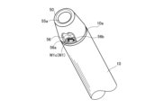
- FIG. 2 is a perspective view showing the vicinity of the distal end of an inner sheath constituting a stent delivery device in an embodiment of the present invention, and is a perspective view showing typically the vicinity of the distal end of the inner sheath.
- FIG. 2 is a perspective view showing the vicinity of the distal end of an inner sheath constituting a stent delivery device in an embodiment of the present invention, and is a see-through view for explaining the inside of the inner sheath.
- 11A to 11C are diagrams illustrating the bending motion of a movable part of an inner sheath constituting a stent delivery device in an embodiment of the present invention.
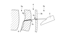
- FIG. 2 is a diagram for explaining the structure of the distal end portion of the inner sheath in an embodiment of the present invention, showing a state in which a stent is not attached to the distal end portion of the inner sheath.
- FIG. 13 is a diagram for explaining the structure of the distal end portion of the inner sheath in an embodiment of the present invention, and illustrates the state in which the second tube portion is compressed when both of the two operating wires are pulled proximally.
- FIG. 2 is a diagram for explaining the structure of the distal end portion of the inner sheath in an embodiment of the present invention, showing a state in which a stent is attached to the distal end portion of the inner sheath.
- 1 is a plan view showing an outer sheath of a stent delivery device according to an embodiment of the present invention.
- FIG. 1 is a plan view showing a stent attached to a stent delivery device in an embodiment of the present invention.
- FIG. 1 is a plan view showing an operating device of a stent delivery device in an embodiment of the present invention.
- 1 is a plan view showing a second rack member and a second operating knob included in the operating device of the stent delivery device in an embodiment of the present invention.
- FIG. 3 is a plan view showing a first rack member and a first operating knob included in an operating device of a stent delivery device in an embodiment of the present invention.
- FIG. 1 is a plan view showing a state in which a distal end portion of an inner sheath is deflected in one direction by an operating device of a stent delivery device in an embodiment of the present invention.
- FIG. 13 is a plan view showing a state in which the distal end portion of the inner sheath is deflected in another direction by the operating device of the stent delivery device in the embodiment of the present invention.
- FIG. 1 is a plan view showing a state in which a distal end portion of an inner sheath is compressed by an operating device of a stent delivery device in an embodiment of the present invention.
- FIG. 2 is a conceptual diagram showing an example of use of the stent delivery device in this embodiment, illustrating the first step of stent placement.
- FIG. 2 is a conceptual diagram showing an example of use of the stent delivery device in this embodiment, illustrating the second step of stent placement.
- FIG. 1 is a plan view showing a state in which a distal end portion of an inner sheath is compressed by an operating device of a stent delivery device in an embodiment of the present invention.
- FIG. 2 is a conceptual diagram showing an example of use of the stent delivery device in this embodiment, illustrating
- FIG. 13 is a conceptual diagram showing an example of use of the stent delivery device in this embodiment, illustrating the third step of stent placement.
- FIG. 13 is a conceptual diagram showing an example of use of the stent delivery device in this embodiment, illustrating the fourth step of stent placement.
- FIG. 13 is a conceptual diagram showing an example of use of the stent delivery device in this embodiment, illustrating the fifth step of stent placement.
- FIG. 13 is a conceptual diagram showing an example of use of the stent delivery device in this embodiment, illustrating the sixth step of stent placement.
- a stent delivery device according to an embodiment of the present invention will be described with reference to the drawings.
- the inside of the patient's body is defined as the distal side
- the side closest to the user is defined as the proximal side, based on the user of the stent delivery device.
- the drawings referred to in this specification are not necessarily drawn to exact scale with respect to the actual dimensions, and some parts have been exaggerated or simplified to show the configuration according to the present invention in a schematic manner.
- Figure 1 is a plan view of a stent delivery device 1 with a stent 70 attached in an embodiment of the present invention.
- the stent delivery device 1 in this embodiment is used to place a stent 70 in a puncture hole formed in the wall of a lumen in the body.
- the stent delivery device 1 is generally configured to include an inner sheath 10, an outer sheath 30, a connecting member 60, a Y connector 66, and an operating device 100.
- the stent delivery device 1 also has operating wires W1, W2 (see, for example, Figures 4A and 4B) arranged along the axial direction of the inner sheath 10 so that the operating device 100 can deflect and compress the movable part 20 of the inner sheath 10.
- the inner sheath 10 is a long member made of a flexible material and has a tubular structure with an inner cavity formed along the axial direction.
- the inner sheath 10 has a movable part 20 at the distal end (upper side in Figure 1) that is inserted into the body, which can be deflected left and right.
- a tip chip 50 is attached to the distal end 10a of the inner sheath 10.
- the proximal end 10b of the inner sheath 10 is connected to the operating device 100 (see Figure 9).
- the distal end of the inner sheath 10 can be fitted with a stent 70.
- the stent 70 is formed in a tubular shape, and the distal end of the inner sheath 10 can be fitted to the distal end of the inner sheath 10 by inserting the distal end of the inner sheath 10 through a through hole formed inside the stent 70.
- the stent 70 fitted to the inner sheath 10 is placed in the stent placement section 15, which is a predetermined range of the distal end of the inner sheath 10.
- the stent 70 attached to the distal end of the inner sheath 10 is restricted from moving proximally by the outer sheath 30 disposed on the proximal side of the stent 70.
- the stent 70 is pushed out by the outer sheath 30 and comes out of the distal end 10a and tip tip 50 of the inner sheath 10.
- the outer sheath 30 is attached so as to fit over the proximal end (lower side in FIG. 1) of the inner sheath 10.
- the outer sheath 30 is composed of a tube member with a lumen formed along the axial direction.
- the inner sheath 10 is inserted into the lumen of the outer sheath 30, and the outer sheath 30 is freely movable in the axial direction relative to the inner sheath 10.
- the proximal end of the outer sheath 30 is provided with a connector 35 that is detachably attached to the connector 65 of the connection member 60.
- the connecting member 60 is a member that protects the proximal end of the inner sheath 10 and is configured so that a Y connector 66 can be connected to introduce a contrast agent or a guide wire into the inner cavity of the inner sheath 10.
- the connecting member 60 is a hollow member, and the inner sheath 10 is inserted inside the connecting member 60.
- the proximal end 60b of the connecting member 60 is connected to the distal end 100a of the operating device 100.
- the distal end of the connecting member 60 is provided with a connector 65 that is detachably attached to the connector 35 of the outer sheath 30.
- the operating device 100 is a device for an operator to operate, and is placed outside the body during use.
- the distal end 100a of the operating device 100 is fixed to the proximal end 10b of the inner sheath 10 and the proximal end 60b of the connecting member 60 (see FIG. 9).
- operating wires W1, W2 are attached to the distal end of the inner sheath 10, and the operating device 100 is configured to be able to deflect and compress the movable part 20 of the inner sheath 10 by displacing the operating wires W1, W2 in the axial direction.
- Figure 2 is a plan view showing a state in which the outer sheath 30 has been removed from the stent delivery device 1 in an embodiment of the present invention.
- Figure 3 is a cross-sectional view taken along line A-A in Figure 2.
- the inner sheath 10 is a flexible, long, thin member. When placing the stent 70, the distal end of the inner sheath 10 can be inserted into the body to reach the desired location inside the body.
- the distal end of the inner sheath 10 is provided with a stent placement section 15 for mounting the stent 70.
- the stent placement section 15 is located on the distal side of the outer sheath 30 when the inner sheath 10 is inserted through the outer sheath 30, and the position of the stent placement section 15 can be adjusted appropriately by adjusting the length of the outer sheath 30. Note that the stent placement section 15 may be determined so that the stent 70 can be stably held by providing a section with an outer diameter larger than the through hole of the stent 70 at the distal end of the inner sheath 10.
- the distal end of the inner sheath 10 is provided with a movable part 20 that can be bent and compressed using the operating device 100. Note that bending in this specification includes curving in the shape of a bow.
- the inner sheath 10 has a tubular structure with a lumen formed along its extension direction.
- a main lumen 11 is formed along the axial direction of the inner sheath 10 at approximately the center of the cross-section of the inner sheath 10.
- the main lumen 11 is formed so as to open at the distal end 10a and the proximal end 10b of the inner sheath 10.
- Wire lumens 11a, 11b, 12a, 12b for inserting the first and second operating wires W1, W2 are formed in the tube wall between the outer peripheral surface of the inner sheath 10 and the main lumen 11.
- the inner sheath 10 is formed with a pair of wire lumens 11a, 11b and a pair of wire lumens 12a, 12b, i.e., a total of four wire lumens 11a, 11b, 12a, 12b.
- Each of the wire lumens 11a, 11b, 12a, 12b is formed to open at the distal end 10a and proximal end 10b of the inner sheath 10, similar to the main lumen 11.
- a first operating wire W1 is inserted through the pair of wire lumens 11a, 11b, and a second operating wire W2 is inserted through the pair of wire lumens 12a, 12b.
- the pair of wire lumens 11a, 11b and the pair of wire lumens 12a, 12b are respectively provided at positions that are mutually opposite, approximately 180 degrees, with respect to the central axis of the inner sheath 10.
- the inner sheath 10 is preferably set to appropriate dimensions according to the placement site of the stent 70, and although there is no particular limitation, the radial dimension can be, for example, about 2 to 20 mm, and the axial dimension can be, for example, about 20 to 300 cm.
- the range of the movable part 20 can be appropriately set according to the placement site of the stent 70, and although there is no particular limitation, it can be, for example, in the range of about 2 to 10 cm from the distal end 10a of the inner sheath 10 (i.e., the dimension L1 in Figure 2 is about 2 to 10 cm).
- the material of the inner sheath 10 is preferably a flexible material that allows the inner sheath 10 to be flexibly deformed when inserted into the body and is also a material that is not harmful to the human body, and may be a biocompatible polymer material such as polyurethane, polyethylene, polypropylene, or a fluororesin such as polytetrafluoroethylene, and it is particularly preferable to use polytetrafluoroethylene.
- the inner sheath 10 in this embodiment is configured to include a first tube portion (solid structure portion) 21 on the proximal side and a second tube portion (porous structure portion) 22 on the distal side, as will be described later with reference to Figures 6A, 6B, and 6C.
- the inner sheath 10 may be provided with a braided layer in which a reinforcing member made of braided wire material such as stainless steel is arranged.
- the inner sheath 10 may have multiple lumens or may be a multi-layer tube.
- Figure 4A is a perspective view showing the vicinity of the distal end 10a of the inner sheath 10 constituting the stent delivery device 1 in an embodiment of the present invention, and is a perspective view that typically shows the vicinity of the distal end 10a of the inner sheath 10.
- Figure 4B is a perspective view showing the vicinity of the distal end of the inner sheath constituting the stent delivery device in an embodiment of the present invention, and is a see-through view for explaining the inside of the inner sheath. Note that the main lumen 11 is omitted in Figure 4B.
- Figure 5 is a view for explaining the bending operation of the movable part 20 of the inner sheath 10 constituting the stent delivery device 1 in an embodiment of the present invention.
- the distal end 10a of the inner sheath 10 is provided with a tip tip 50 made of, for example, metal.
- the tip tip 50 protects the distal end 10a of the inner sheath 10 and also serves to reduce the insertion resistance of the inner sheath 10 into the body.
- the tip tip 50 is fixed to the distal end 10a of the inner sheath 10.
- by forming the tip tip 50 into a tapered shape it is possible to improve the ease of insertion into a puncture hole formed in the wall of a lumen in the body and the ability to break through body tissue.
- the distal tip 50 has a through hole 55a along its central axis.
- the through hole 55a is connected to the main lumen 11 of the inner sheath 10, and the main lumen 11 of the inner sheath 10 is connected to the outside through this through hole 55a.
- the distal tip 50 has a pair of recesses 56, 57 formed on its proximal side.
- Wire insertion holes 56a, 56b are formed in the recess 56.
- wire insertion holes 57a, 57b are formed in the recess 57.
- the wire insertion holes 56a, 56b, 57a, 57b are provided to correspond to the opening positions of the wire lumens 11a, 11b, 12a, 12b that open at the distal end 10a of the inner sheath 10, respectively, and the first and second operating wires W1, W2 inserted into the wire lumens 11a, 11b, 12a, 12b are inserted into the wire insertion holes 56a, 56b, 57a, 57b, respectively.
- first operating wire W1 is inserted through the wire lumens 11a and 11b
- second operating wire W2 is inserted through the wire lumens 12a and 12b.
- the first operating wire W1 and the second operating wire W2 are made of a metal (stainless steel, etc.) that is flexible enough to bend in accordance with the curvature of the inner sheath 10 including the movable part 20.
- the first operating wire W1 which is inserted through the wire lumens 11a and 11b, is inserted through the wire insertion holes 56a and 56b of the distal tip 50, which are provided corresponding to the wire lumens 11a and 11b.
- the first operating wire W1 is folded back at the folded back intermediate portion W1c, which corresponds to approximately halfway along the axial direction of the wire, in the recess 56 of the distal tip 50.
- the folded back intermediate portion W1c as a reference, the operating wire W1a on one end side is inserted through the wire lumen 11a via the wire insertion hole 56a, and the operating wire W1b on the other end side is inserted through the wire lumen 11b via the wire insertion hole 56b.
- the operating wires W1a and W1b are pulled proximally, and the folded back intermediate portion W1c is configured to engage with the distal tip 50 due to the tensile force.
- the second operating wire W2 which is inserted through the wire lumens 12a and 12b, is inserted through the wire insertion holes 57a and 57b of the distal tip 50, which are provided corresponding to the wire lumens 12a and 12b.
- the second operating wire W2 is folded back at the folded back intermediate portion W2c, which corresponds to approximately halfway along the axial direction of the wire, in the recess 57 of the distal tip 50.
- the folded back intermediate portion W2c as a reference, the operating wire W2a on one end side is inserted through the wire lumen 12a via the wire insertion hole 57a, and the operating wire W2b on the other end side is inserted through the wire lumen 12b via the wire insertion hole 57b.
- the operating wires W2a and W2b are pulled proximally, and the folded back intermediate portion W2c is configured to engage with the distal tip 50 by the tensile force.
- the operation wire W1a on one end side constituting the first operation wire W1 extends along the inner sheath 10 while being inserted into the wire lumen 11a, and the proximal end of the operation wire W1a is guided inside the operation device 100.
- the operation wire W1b on the other end side constituting the first operation wire W1 extends along the inner sheath 10 while being inserted into the wire lumen 11b, and the proximal end of the operation wire W1b is guided inside the operation device 100.
- the proximal end of the operation wire W1a and the proximal end of the operation wire W1b are connected and fixed to the first rack member 200 of the operation device 100.
- the operation wire W2a at one end of the second operation wire W2 extends along the inner sheath 10 while being inserted into the wire lumen 12a, and the proximal end of the operation wire W2a is guided inside the operation device 100.
- the operation wire W2b at the other end of the second operation wire W2 extends along the inner sheath 10 while being inserted into the wire lumen 12b, and the proximal end of the operation wire W2b is guided inside the operation device 100.
- the proximal end of the operation wire W2a and the proximal end of the operation wire W2b are connected and fixed to the second rack member 300 of the operation device 100.
- the longitudinal middle portion 10c including the proximal end of the inner sheath 10 is preferably flexible and deformable to match the path along which the stent 70 is transported inside the body, and has excellent mechanical strength such as rigidity.
- the movable portion 20 located at the distal end of the inner sheath 10 is preferably flexible and deflectable by the user's operation.
- the distal end of the inner sheath 10 where the movable portion 20 is provided is preferably capable of deflecting in response to the deflection operation by the operating device 100, and preferably has higher flexibility than the middle portion 10c of the inner sheath 10.
- the inner sheath 10 in this embodiment has a portion with excellent flexibility on the distal side constituting the movable portion 20, and a portion with excellent mechanical strength on the proximal side including the intermediate portion 10c.
- the inner sheath 10 in this embodiment has both flexibility and rigidity, making it easy to operate.
- Figure 6A is a diagram for explaining the structure of the distal end of the inner sheath 10 in an embodiment of the present invention, and is a diagram showing a state in which a stent 70 is not attached to the distal end of the inner sheath 10.
- Figure 6B is a diagram for explaining the structure of the distal end of the inner sheath in an embodiment of the present invention, and is a diagram showing a state in which the second tube portion is compressed when both of the two operating wires are pulled proximally.
- Figure 6C is a diagram for explaining the structure of the distal end of the inner sheath in an embodiment of the present invention, and is a diagram showing a state in which a stent 70 is attached to the distal end of the inner sheath 10. Note that the proximal side of the stent 70 is omitted in Figure 6C.
- the tube member constituting the inner sheath 10 has a first tube portion 21 on the proximal side and a second tube portion 22 that is connected to the distal end of the first tube portion 21 so as to be continuous with it.
- the first tube section 21 is a solid structural section whose flexibility does not change substantially even when subjected to a compressive force in the axial direction.
- the first tube section 21 is disposed mainly in the middle section 10c of the inner sheath 10 and constitutes the inner sheath 10.
- the second tube section 22 is a porous structure section made of a porous tube that is compressed and hardened according to the degree of compressive force acting in the axial direction, and returns to its original soft state when the compressive force is released.
- the second tube section 22 is continuous with the first tube section 21, and constitutes the range from the boundary section 23 with the first tube section 21 to the distal end 10a of the inner sheath 10.
- the length of the second tube portion 22 from the distal end 10a of the inner sheath 10 to the boundary portion 23 is not particularly limited, and the dimension L2 in the longitudinal direction of the second tube portion 22 may be shorter or longer than the dimension in the longitudinal direction of the movable portion 20 (dimension L1 in FIG. 2), or may be the same.
- the movable portion 20 can be provided so as to include at least a portion of the second tube portion 22.
- Both the first tube portion 21 and the second tube portion 22 can be made of a biocompatible polymeric material, such as polyurethane, polyethylene, polypropylene, or a fluororesin such as polytetrafluoroethylene.
- the first tube portion 21 and the second tube portion 22 are preferably made of the same material, but may be made of different materials.
- the inner sheath 10 is preferably made of the first tube portion 21 and the second tube portion 22, both of which are made of polytetrafluoroethylene.
- the first tube portion 21 and the second tube portion 22 may each be a single-layer tube made of a single material, or may be made by laminating multiple layers made of different materials.
- a specific example of the first tube portion 21 made by laminating multiple layers is a configuration in which a polytetrafluoroethylene tube constituting the inner layer is covered with a fluororesin heat-shrinkable tube.
- the second tube section 22 is characterized by being porous and containing more pores than the first tube section 21.
- the first tube section 21 and the second tube section 22 each have different physical properties, as exemplified below.
- the specific gravity of the first tube section 21 is not particularly limited, but is preferably 0.80 to 2.20.
- the specific gravity of the second tube section 22 is not particularly limited, but is preferably 0.10 to 2.00.
- the ratio of the specific gravity of the first tube section 21 to the specific gravity of the second tube section 22 (second tube section 22/first tube section 21) is preferably 0.30 to 0.95, more preferably 0.40 to 0.90, and even more preferably 0.50 to 0.90 in at least a portion of the length of the inner sheath 10.
- the proximal side of the inner sheath 10 has excellent rigidity due to the action of the first tube section 21, and the distal side of the inner sheath 10 has excellent flexibility due to the action of the second tube section 22.
- the specific gravity test method complies with the liquid weighing method described in JIS Z 8807, and the standard substance is water.
- the ratio of the radial crushing strength of the first tube section 21 to the radial crushing strength of the second tube section 22 is preferably 0.20 or more and less than 1.0.
- the ratio of the radial crushing strength is 0.50 or more and less than 1.0, a certain radial crushing strength can be secured even in the second tube section 22, and the inner sheath 10 has excellent mechanical strength.
- the ratio of the radial crushing strength is 0.20 or more and less than 0.50, the inner sheath 10 has excellent mechanical strength and flexibility.
- the radial crushing strength was measured by performing a radial compression test using a bending and crushing rigidity measuring device, and measuring the reaction force when pressed 0.5 mm.
- the tube length was 10 mm
- the shape of the compressed section was flat
- the pressing speed was 1.0 mm/min.
- the ratio of the bending stress in the first tube section 21 to the bending stress in the second tube section 22 is preferably 0.10 or more and less than 1.0.
- the ratio of the bending stress is 0.40 or more and less than 1.0, a certain bending stress can be secured in the second tube section 22 as well, and the inner sheath 10 has excellent mechanical strength.
- the ratio of the bending stress is 0.10 or more and less than 0.40, the inner sheath 10 has excellent mechanical strength and flexibility.
- the bending stress was measured by performing a bending test using a bending and crushing stiffness measuring device and measuring the reaction force when pressed 5.0 mm.
- the tube length is 100 mm
- the compressed section shape is cylindrical with a diameter of 10 mm
- the support distance is 60 mm
- the support member shape is cylindrical with a diameter of 10 mm
- the pressing speed is 50 mm/min.
- the ratio of the kink resistance of the first tube section 21 to the kink resistance of the second tube section 22 is preferably 20% or more and less than 100%, more preferably 20-90%, and even more preferably 20-80%.
- the kink resistance is measured by performing a buckling test using a vice and measuring the distance between the vises when the tube is completely buckled. A 300 mm long tube is bent and clamped in a vice with a width of about 200 mm, and the distance between the vises is gradually reduced until the tube is completely buckled. The distance between the vises when the tube buckles is the measured value. The smaller this measured value, the more kink resistant the tube is.
- the structure of the boundary 23 between the first tube section 21 and the second tube section 22 is not particularly limited.
- a transition section whose structure changes gradually may be provided at the boundary 23 between the first tube section 21 and the second tube section 22.
- the longitudinal dimension of the transition section is not particularly limited.
- the load is not concentrated at a single point when the inner sheath 10 is bent, so the inner sheath 10 is less likely to break or be crushed when bent, and the kink resistance of the inner sheath 10 is improved.
- the radial crushing strength of the inner sheath 10 is improved by the action of the first tube section 21, and the rigidity of the inner sheath 10 can be increased.
- the second tube portion 22 itself may be gradually changed to a structure having greater flexibility as it approaches the distal side of the inner sheath 10. This increases flexibility and bendability as it approaches the distal side of the inner sheath 10, improving the operational responsiveness of the movable portion 20 provided at the distal end of the inner sheath 10. Furthermore, the flexibility and bendability of the inner sheath 10 gradually increases toward the distal side without any sudden changes, resulting in a configuration that is suited to the movable portion 20, which bends more significantly on the distal side, and allowing the movable portion 20 to be deflected smoothly.
- the inner and outer circumferential surfaces of the inner sheath 10 are smooth without any seams or steps in the first tube portion 21, the second tube portion 22, and the boundary portion 23 between the first tube portion 21 and the second tube portion 22.
- various treatment tools can be smoothly inserted into the main lumen 11.
- the outer circumferential surface of the inner sheath 10 can be smoothly inserted into a puncture hole formed in the wall of a lumen in the body or a channel of an endoscope, and the stent 70 can be smoothly attached to and removed from the inner sheath 10.
- the insertion resistance of the inner sheath 10 increases in this portion, and operability is significantly reduced.
- the method of manufacturing the inner sheath 10 is not particularly limited, and examples of the method include extrusion molding, injection molding, and a method of wrapping a film into a tube shape. If necessary, stretching, chemical treatment, plasma treatment, laser treatment, electronic cross-linking, etc. may be performed.
- an unsintered tube may be manufactured by extrusion molding, and only the portion corresponding to the first tube portion 21 may be sintered. Then, the portion corresponding to the second tube portion 22 may be stretched to make it porous, and then sintered to manufacture the inner sheath 10 having the first tube portion 21 and the second tube portion 22 as an integrated tube.
- the second tube portion 22 is preferably isotropic in the radial direction of the inner sheath 10. This allows the second tube portion 22 to have similar flexibility in any direction, making it easier to position the movable portion 20, which includes at least a portion of the second tube portion 22.
- the second tube section 22 is a porous tube and is configured to include numerous voids (holes) therein.
- voids holes
- the folded-back intermediate portions W1c, W2c of the two operating wires W1, W2 are engaged so as to be folded back at the distal end 10a of the inner sheath 10, and the operating wires W1, W2 can be displaced in the axial direction by the operating device 100.
- the deflection operation of the movable part 20 can be performed by moving either the first rack member 200 or the second rack member 300 proximally, but a compression operation can also be performed by simultaneously moving both the first rack member 200 and the second rack member 300 proximally.
- both the first rack member 200 and the second rack member 300 move proximally at the same time, both of the two operating wires W1 and W2 are pulled proximally at the same time, and a force that pulls the distal end 10a of the inner sheath 10 proximally acts on the distal end 10a of the inner sheath 10.
- This force acts as a compressive force that compresses the inner sheath 10 in the axial direction.
- the first tube portion 21 is hardly compressed and its axial length does not change, while the second tube portion 22 is subjected to an axial compressive force and compressed so that its axial length (dimension L3 in FIG. 6B) becomes shorter than its length when no compressive force is applied (dimension L2 in FIG. 6A).
- first tube portion 21 is also compressed to a certain extent so that its axial length becomes shorter, but the second tube portion 22, which is made of a porous structure, is more significantly affected by the axial compressive force, and the characteristics of the second tube portion 22 change significantly.
- the second tube portion 22 When the second tube portion 22 is subjected to a compressive force, it becomes harder and has higher rigidity than the second tube portion 22 when it is not subjected to a compressive force. Furthermore, when the axial compressive force applied by the two operating wires W1 and W2 is released, the second tube portion 22 returns to its original state, becomes soft, and recovers its flexibility.
- the stent delivery device 1 in this embodiment can be freely changed between a state in which the second tube portion 22 is hard and has high rigidity, and a state in which the second tube portion 22 is soft and has high flexibility, by operating the operating device 100.
- the rigidity of the second tube portion 22 is high, and the insertability into the puncture hole is improved.
- the second tube portion 22 is soft, the flexibility of the second tube portion 22 is high, and the second tube portion 22 can be flexibly deflected.
- the stent 70 is also mounted on the stent placement section 15 at the distal end of the inner sheath 10.
- the stent 70 mounted on the stent placement section 15 is preferably mounted at a position that does not cover the movable section 20 so as not to interfere with the deflection of the movable section 20.
- the stent placement section 15 is provided on the first tube section 21, and the stent 70 mounted on the stent placement section 15 of the inner sheath 10 is disposed proximal to the boundary section 23 between the first tube section 21 and the second tube section 22.
- the second tube section 22 can be changed between a hard state and a soft state by the operation of the operating device 100, but by disposing the stent 70 proximal to the boundary section 23, the stent 70 can be transported stably without being affected by the change in state of the second tube section 22, and the movable section 20 provided on the second tube section 22 can be smoothly operated without being affected by the positioning of the stent 70.
- the second tube portion 22 is made of a porous structure containing many voids (holes) therein, and has a structure that is easily visible in an ultrasound image that visualizes a reflected signal from the interface of materials.
- the second tube portion 22 made of a porous structure has excellent ultrasound visibility.
- connection member 60 is configured to integrally include a tubular first protective member 61, a branching member 62, and a tubular second protective member 63, and is disposed on the distal side of the operating device 100.
- the connection member 60 is a hollow member formed separately from the inner sheath 10 and the operating device 100, and is made of a metal such as stainless steel.
- the inner sheath 10 is inserted and fixed inside the first protective member 61 and the second protective member 63, and in this section the inner sheath 10 is protected by the first protective member 61 and the second protective member 63.
- the branching member 62 is interposed between the first protective member 61 and the second protective member 63 to protect the inner sheath 10, and is configured to allow a Y connector 66 that communicates with the main lumen 11 of the inner sheath 10 to be attached.
- the main lumen 11 is blocked at the position where it communicates with the Y connector 66 or proximal thereto, so that contrast medium, etc. introduced into the main lumen 11 does not leak from the proximal end 10b of the inner sheath 10.
- the Y connector 66 is a hollow member formed separately from the inner sheath 10, the operating device 100, and the connection member 60.
- the Y connector 66 is formed, for example, by injection molding of resin.
- the Y connector 66 has a sleeve portion that is inserted into the branching member 62 and is bifurcated into a first port portion 67 and a second port portion 68.
- the first port portion 67 has an opening with a valve or the like on its proximal side.
- a contrast agent or the like can be introduced from the opening of the first port portion 67, so that a contrast agent or the like can be introduced into the main lumen 11 of the inner sheath 10.
- the second port portion 68 has an opening whose opening diameter can be adjusted by the handle portion 69.
- a guidewire or the like can be introduced from the opening of the second port portion 68, so that the guidewire or the like can be introduced into the main lumen 11 of the inner sheath 10.
- connection member 60 The proximal end 60b of the connection member 60 is connected to the distal end 100a of the operating device 100.
- a connector 65 is provided at the distal end of the connection member 60.
- the inner sheath 10 can be inserted into the inside of the connector 65, and the inner sheath 10 extends from the distal end opening 65a of the connector 65 through the inside of the connection member 60 to the operating device 100.
- the connector 65 is configured to be detachable from the connector 35 provided at the proximal end of the outer sheath 30.
- the connector 65 is made of, for example, polycarbonate, high-density polyethylene, polymethylpentene, polyacetal, polyamide, polypropylene, etc.
- the method of connecting the distal end of the connection member 60 to the connector 65 is not particularly limited, and for example, bonding with an adhesive, fusion, crimping, etc. can be used.
- Figure 7 is a plan view showing the outer sheath 30 of the stent delivery device 1 in an embodiment of the present invention.
- the outer sheath 30 is a flexible, long, thin-diameter member.
- the outer sheath 30 is made of a tube member that can be attached to the outer periphery of the inner sheath 10, and is used as an extrusion member that pushes the stent 70 attached to the stent placement section 15 of the inner sheath 10 distally.
- the lumen formed inside the outer sheath 30 opens at a distal end opening 30a located at the distal end of the outer sheath 30 and a proximal end opening 30b located at the proximal end of the outer sheath 30.
- a connector 35 is provided at the proximal end of the outer sheath 30.
- a base end opening 35b is formed at the proximal end of the connector 35.
- the inner sheath 10 can be inserted into the lumen of the outer sheath 30 by inserting the distal end 10a (distal tip 50) of the inner sheath 10 from this base end opening 35b. That is, inside the connector 35 and outer sheath 30 shown in FIG. 7, a through hole is formed that communicates from the base end opening 35b to the distal end opening 30a, and the inner diameter of the through hole is equal to or greater than the maximum outer diameter of the inner sheath 10.
- the connector 35 is configured to be detachable from the connector 65 provided at the distal end of the connection member 60.
- the connector 35 of the outer sheath 30 is attached to the connector 65 of the connection member 60, the outer sheath 30 is fixed to the connection member 60 and the inner sheath 10 and cannot move in the axial direction.
- the connector 35 of the outer sheath 30 is detached from the connector 65 of the connection member 60, the outer sheath 30 is separated from the connection member 60 and becomes movable relative to the inner sheath 10 in the axial direction.
- the material of the tube member that constitutes the outer sheath 30 is not particularly limited, and may be, for example, a fluororesin such as polytetrafluoroethylene, polyethylene, polyurethane, polyamide, or the like.
- the connector 35 is made of, for example, polycarbonate, high-density polyethylene, polymethylpentene, polyacetal, polyamide, polypropylene, or the like.
- the method of connecting the proximal end of the outer sheath 30 and the connector 35 is not particularly limited, and may be, for example, adhesive bonding, fusion, crimping, or the like.
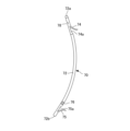
- the stent 70 is configured to have a flexible tube body 72.
- the tube body 72 has a through hole formed therein, and has a distal end opening 72a that opens at the distal end of the tube body 72, and a proximal end opening 72b that opens at the proximal end of the tube body 72.
- the tube body 72 can be configured from a plastic tube made of, for example, a fluororesin such as polytetrafluoroethylene, polyethylene, polyurethane, polyamide, or the like.
- the distal end of the tube body 72 is tapered so that its outer diameter and inner diameter decrease toward the distal side, and the inner diameter of the distal end opening 72a is smaller than the inner diameter of the tube body 72.
- a side hole 78 is formed on the proximal side of the distal end opening 72a of the tube body 72. The side hole 78 is connected to a through hole inside the tube body 72.
- a distal end flap 74 is formed proximal to the side hole 78.
- the distal end flap 74 is formed by cutting the outer periphery of the tube body 72 in the axial direction along the flap opening 74a and raising the cut piece to the outside of the tube body 72.
- the through hole of the tube body 72 is in communication with the outside through the flap opening 74a.
- the distal end opening 72a, the side hole 78, and the flap opening 74a have the function of taking in bile and the like into the inside of the stent 70.
- the distal end flap 74 gradually protrudes outward from the base end of the distal end flap 74 in the proximal end direction so that when the stent 70 is inserted distally into a puncture hole in the body lumen wall, it is folded along the inner wall of the puncture hole toward the tube body 72.
- the distal end flap 74 is positioned so that it spreads outward within the body lumen (e.g., the intrahepatic bile duct), and functions as an engagement member that hooks onto the body lumen wall (e.g., the intrahepatic bile duct wall).
- a proximal end flap 75 is formed on the distal side of the proximal end opening 72b of the tube body 72.
- the proximal end flap 75 is formed by cutting the outer periphery of the tube body 72 in the axial direction along the flap opening 75a and raising the cut piece to the outside of the tube body 72.
- the through hole of the tube body 72 is connected to the outside through the flap opening 75a.
- the proximal end opening 72b and the flap opening 75a have the function of discharging bile and the like that has been taken into the internal through hole from the distal side of the stent 70.
- the proximal end flap 75 gradually protrudes outward from the base end of the proximal end flap 75 in the direction of the distal end.
- the proximal end flap 75 is disposed so as to spread outward within the body lumen (e.g., the stomach) and functions as an engagement member that hooks onto the wall of the body lumen (e.g., the stomach wall).
- a marker 76 may be provided on the distal side of the proximal end flap 75.
- the marker 76 may be colored so that it is visible in an image captured by an endoscopic camera.
- the marker 76 may be formed by attaching a metal ring made of, for example, platinum, gold, or a platinum-iridium alloy so that its position can be detected in an X-ray fluoroscopic image.
- the tube body 72 is preferably formed into an arc shape with a predetermined radius of curvature, for example, so as to fit the shape of the placement site inside the body.
- the predetermined radius of curvature is not particularly limited, but is preferably 40 to 200 mm.
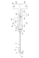
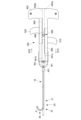
- Figure 9 is a plan view showing the operating device 100 of the stent delivery device 1 in an embodiment of the present invention.
- Figure 9 shows the internal configuration of the operating device 100 in a see-through manner.
- Figure 10A is a plan view showing the second rack member 300 and the second operating knob 520 included in the operating device 100 of the stent delivery device 1 in an embodiment of the present invention.
- Figure 10B is a plan view showing the first rack member 200 and the first operating knob 510 included in the operating device 100 of the stent delivery device 1 in an embodiment of the present invention.
- the operating device 100 includes a flat controller housing 400 having an internal cavity, a first rack member 200 and a second rack member 300 housed within the controller housing 400, and a pinion member 500 disposed between the first rack member 200 and the second rack member 300.
- the controller housing 400 is formed in a roughly T-shape with an internal cavity, and has a roughly rectangular main body 410, a support handle portion 420 integrally provided at the proximal end, which is one end side in the longitudinal direction of the main body 410, and a wire insertion portion 430 at the distal end, which is the other end side in the longitudinal direction of the main body 410, through which the first operating wire W1 and the second operating wire W2 are respectively inserted.
- the longitudinal direction of the main body 410 is the direction along the extension direction of the operating wires W1, W2 inserted into the inner sheath 10.
- the longitudinal direction referred to below is based on the longitudinal direction of this main body 410.
- the controller housing 400 has a symmetrical shape with the longitudinal center line C passing through the center of the width of the main body 410 as the line of symmetry.
- the controller housing 400 is configured, for example, by combining a halved base and a lid body, which are roughly divided into two equal halves in the thickness direction, in a removable manner.
- the base and lid body that configure the controller housing 400 can be secured together by screwing, gluing, etc., when stacked facing each other.
- the base and lid body are roughly the same shape and are each made of resin, etc.
- a first slide guide portion 406 and a second slide guide portion 407 are formed on both side surfaces of the controller housing 400.
- An opening is formed on the side surface of the first slide guide portion 406 for exposing the first operation knob 510 of the first rack member 200 to the side, and an opening is formed on the side surface of the second slide guide portion 407 for exposing the second operation knob 520 of the second rack member 300 to the side.
- the support handle portion 420 of the controller housing 400 includes a first handle portion 421 and a second handle portion 422, each of which is substantially rectangular and extends laterally perpendicular to the main body portion 410.
- the support handle portion 420 and the main body portion 410 form a substantially T-shape.
- the proximal edge 423 of the support handle portion 420 includes a support portion 423a against which the operator's palm rests.
- This support portion 423a is formed into a gently curved surface that is generally convex from one end to the other toward the proximal side. Corners 423b, 423c continuing to both ends of the support portion 423a are chamfered. Because the support portion 423a is gently curved and each corner 423b, 423c is chamfered, the operator can easily place his or her palm against the support portion 423a without feeling uncomfortable, thereby improving the operability of the operating device 100.
- the distal end edges of the first handle portion 421 and the second handle portion 422 that constitute the support handle portion 420 respectively constitute finger locking portions 421a, 422a on which the operator's fingers can be hooked.
- These finger locking portions 421a, 422a are formed into gently curved surfaces that are roughly concave toward the proximal side.
- the outer corners 421b, 422b that are continuous with the finger locking portions 421a, 422a are chamfered.
- the support handle portion 420 forms an approximately T-shape together with the main body portion 410, but it may be any shape that has a surface that can be pressed against the palm, such as a shape that forms an approximately L-shape together with the main body portion 410, or it may be any shape that has a structure that allows fingers to be engaged, such as a finger insertion ring that can be supported by passing the fingers through.
- the wire insertion portion 430 has a thin tubular sleeve portion 431 protruding from the distal end of the controller housing 400, a wire inlet 432 that communicates from the inside of the sleeve portion 431 to the inside of the controller housing 400, and a gate portion 433 disposed adjacent to the wire inlet 432.
- the gate portion 433 includes a pair of cylindrical portions 433a, 433b provided on the controller housing 400.
- the cylindrical portions 433a, 433b that constitute the gate portion 433 may be formed of rotatable rollers.
- the inner sheath 10 has its proximal end 10b fixed inside the sleeve portion 431 and is connected to the controller housing 400.
- the means for fixing the inner sheath 10 to the sleeve portion 431 but for example, a means can be used in which the proximal end 10b of the inner sheath 10 is pressed into the sleeve portion 431 and then glued or welded to the inner surface of the sleeve portion 431.
- a heat shrink tube or the like can be used to cover the boundary position between the controller housing 400 and the inner sheath 10, and the cover can be integrated with the controller housing 400.
- the connecting member 60 has its proximal end 60b fixed to the outer periphery of the sleeve portion 431 and is connected to the controller housing 400.
- the means for fixing the inner sheath 10 to the sleeve portion 431 is not particularly limited, but for example, a means can be used in which the sleeve portion 431 is press-fitted into the proximal end 60b of the connecting member 60 and then glued or welded to the inner surface of the proximal end 60b of the connecting member 60.
- the connecting member 60 and the controller housing 400 may be formed integrally.
- the proximal ends of the first operating wire W1 and the second operating wire W2 are passed from inside the sleeve portion 431 through the wire inlet 432 and between the cylindrical portions 433a, 433b of the gate portion 433, and introduced into the controller housing 400. As described below, the first operating wire W1 is fixed to the first rack member 200, and the second operating wire W2 is fixed to the second rack member 300.
- the controller housing 400 has therein a first guide portion 451 that guides the first rack member 200 so that it can be displaced back and forth in the longitudinal direction, and a second guide portion 452 that guides the second rack member 300 so that it can be displaced back and forth in the longitudinal direction.
- the first guide section 451 is formed by two partition walls 441a, 442a extending in the longitudinal direction provided at the center of the controller housing 400, the first slide guide section 406, and a guide wall section 443 within the support handle section 420.
- the second guide section 452 is formed by partition walls 441b, 442b, the second slide guide section 407, and a guide wall section 444 within the support handle section 420.
- a coil spring 455 is disposed on the proximal side of the first guide portion 451, and a coil spring 456 is disposed on the proximal side of the second guide portion 452.
- the coil springs 455, 456 bias the first rack member 200 and the second rack member 300 that have moved to the proximal side, respectively, and serve to return the first rack member 200 and the second rack member 300 to a neutral position in which they are positioned symmetrically on the left and right.
- the coil springs may be disposed on the distal side of the first guide portion 451 and the distal side of the second guide portion 452, or a configuration may be adopted in which no coil springs are provided.
- the partition wall portions 441a and 441b form a partition wall on the distal side in the longitudinal direction, and the proximal ends of the partition wall portions 441a and 441b are connected by a U-shaped curved portion 441c near the position where the pinion member 500 is disposed.
- the partition wall portions 442a and 442b form a partition wall on the proximal side in the longitudinal direction, and the distal ends of the partition wall portions 442a and 442b are connected by a U-shaped curved portion 442c near the position where the pinion member 500 is disposed.
- the curved portion 441c and the curved portion 442c are arranged to be spaced apart in the longitudinal direction, and a space in which the pinion member 500 is disposed is formed.
- the base of the controller housing 400 has a groove 460 between the curved portions 441c and 442c. Although not shown, a groove is also provided at the opposing position of the lid of the controller housing 400. This forms grooves that extend along the longitudinal direction so as to face each other vertically.
- the pinion member 500 is disposed between the curved portions 441c and 442c with its pivot shaft 502 fitted into the groove formed by the groove 460 (and the opposing groove of the lid), and is supported so as to be movable along the longitudinal direction and rotatable.
- the first operating wire W1 and the second operating wire W2 are introduced into the controller housing 400 from the proximal end 10b of the inner sheath 10, branched at cylindrical wire guides 434a and 434b, and guided to the first guide portion 451 and the second guide portion 452, respectively.
- the wire guides 434a and 434b may be composed of rotatable rollers.
- the first operating wire W1 guided to the first guide portion 451 is connected to the first rack member 200.
- the second operating wire W2 guided to the second guide portion 452 is connected to the second rack member 300.
- the first rack member 200 and the second rack member 300 are housed within the controller housing 400 so that they can be moved back and forth in the longitudinal direction of the main body 410, and so that the teeth 220, 320 face each other.
- the first rack member 200 and the second rack member 300 each have an elongated rectangular parallelepiped rack body 210, 310 and a tooth section 220, 320 consisting of a large number of teeth provided on the side surfaces of the rack body sections 210, 310 that face each other.
- the first rack member 200 and the second rack member 300 are installed in the first guide section 451 and the second guide section 452, respectively, with the tooth sections 220, 320 facing each other.
- the rack body 210 of the first rack member 200 has a guide piece 212 on its outer side surface 211 that extends in the longitudinal direction of the rack body 210.
- This guide piece 212 is inserted into an opening formed in the side surface of the first slide guide portion 406.
- a first operation knob 510 that protrudes through this opening to the side of the controller housing 400 is integrally provided on the rack body 210 of the first rack member 200.
- the rack body 310 of the second rack member 300 has a guide piece 312 on its outer side surface 311 that extends in the longitudinal direction of the rack body 310.
- This guide piece 312 is inserted into an opening formed in the side surface of the second slide guide portion 407.
- a second operation knob 520 that protrudes through this opening to the side of the controller housing 400 is integrally provided on the rack body 310 of the second rack member 300.
- the first and second operating knobs 510 and 520 have a rectangular plate shape similar to the first and second handle portions 421 and 422 constituting the support handle portion 420, respectively, and are formed integrally with the first and second rack members 200 and 300, respectively.
- the first and second operating knobs 510 and 520 may have any shape, for example, a rod shape, a ring shape, a trigger shape, etc.
- the first and second operating knobs 510 and 520 may be formed separately from the first and second rack members 200 and 300, respectively, and then fixed to the first and second rack members 200 and 300, respectively.
- the distal edges (left side in Figs. 10A and 10B) of the first operation knob 510 and the second operation knob 520 respectively constitute finger locks 510a, 520a on which the operator's fingers can be hooked.
- These finger locks 510a, 520a are formed into gently curved surfaces that are generally concave toward the proximal side.
- the outer corners 510b, 520b that are continuous with the finger locks 510a, 520a are chamfered.
- Each finger lock 510a, 520a is curved into a concave shape so that the operator can easily hook the fingers on the finger locks 510a, 520a, making it easy to operate the first operation knob 510 and the second operation knob 520.
- each finger retaining portion 510a, 520a is formed with an inner convex portion 510c, 520c that is shaped to smoothly transition to the first rack member 200 and the second rack member 300, respectively.
- These inner convex portions 510c, 520c make it difficult for fingers placed on each finger retaining portion 510a, 520a to come into contact with the main body portion 410 of the controller housing 400, and thus the operability of the first operating knob 510 and the second operating knob 520 is not hindered.
- the first operating knob 510 and the second operating knob 520 are operated by pulling them proximally (towards the support handle portion 420) with fingers hooked on the finger engagement portions 510a, 520a.
- the first rack member 200 is displaced integrally to the proximal side, and in sync with this, the second rack member 300 is displaced distally in the opposite direction.
- the second rack member 300 is displaced integrally to the proximal side, and in sync with this, the first rack member 200 is displaced distally in the opposite direction.
- the index finger can be placed on the finger retaining portion 510a of the first operation knob 510 and the middle finger can be placed on the finger retaining portion 520a of the second operation knob 520, and the first operation knob 510 and the second operation knob 520 can be pulled and operated with each finger.
- the first rack member 200 has a wire fixing portion 511 on its back surface for fixing the proximal end of the first operating wire W1.
- the second rack member 300 has a wire fixing portion 521 on its front surface for fixing the proximal end of the second operating wire W2.
- Each wire fixing portion 511, 521 has the same structure, and the operating wires W1, W2 can be fixed to the first rack member 200 and the second rack member 300, respectively, by screw fastening.
- the wire fixing portion 521 of the second rack member 300 has a groove 521a extending in the longitudinal direction formed on the surface of the rack main body 310, a thin metal tube 521b fitted into this groove 521a, and a threaded portion 521c.
- the threaded portion 521c has a female thread 521d fixed in a recess 310a opening into the outer side surface 311 of the rack main body 310, and a hexagonal socket bolt 521e screwed into the female thread 521d.
- the second operating wire W2 is folded back at the recess 57 of the tip tip 50, and the operating wires W2a and W2b constituting the second operating wire W2 are guided inside the operating device 100.
- the proximal ends of these operating wires W2a and W2b come into contact with the outside of the wire guide 434b and are guided into the groove 521a, and are inserted into the metal tube 521b through the groove 521a.
- the second operating wire W2 is crimped and fixed in the metal tube 521b by crimping the metal tube 521b with the bolt 521e screwed into the female thread 521d.
- the operating wires W2a and W2b protruding to the proximal side of the metal tube 521b are appropriately cut off.
- the proximal end of the second operating wire W2 (the proximal ends of both operating wires W2a and W2b) can be fixed to the second rack member 300 together with the metal tube 521b.
- the tension of the operating wires W2a and W2b can be finely adjusted by loosening the bolt 521e and moving the metal tube 521b and the operating wires W2a and W2b in the longitudinal direction.
- the wire fixing portion 511 of the first rack member 200 is provided on the back side of the rack main body 210, and has a groove 511a, a metal tube 511b fitted into the groove 511a, and a threaded portion 511c formed by a female thread 511d and a bolt 511e.
- the threaded portion 511c is fixed in a recess 210a that opens into the outer side surface 211 of the rack main body 210.
- the first operating wire W1 is folded back at the recess 56 of the distal tip 50, and the operating wires W1a and W1b constituting the first operating wire W1 are guided inside the operating device 100.
- the proximal ends of these operating wires W1a and W1b come into contact with the outside of the wire guide 434a and are guided into the groove 511a, and are inserted into the metal tube 511b through the groove 511a.
- the first operating wire W1 is crimped and fixed in the metal tube 511b by crimping the metal tube 511b with the bolt 511e screwed into the female thread 511d.
- the operating wires W1a and W1b protruding to the proximal side of the metal tube 511b are appropriately cut off.
- the proximal end of the first operating wire W1 (the proximal ends of both operating wires W1a and W1b) can be fixed to the first rack member 200 together with the metal tube 511b.
- the tension of the operating wires W1a and W1b can be finely adjusted by loosening the bolt 511e and moving the metal tube 511b and the operating wires W1a and W1b in the longitudinal direction.
- the pinion member 500 is disposed between the curved portion 441c and the curved portion 442c. As shown in FIG. 9, the pinion member 500 is composed of a gear portion 501 that meshes with each tooth portion 220, 320, and a pivot shaft member 502 that is located approximately at the center of the gear portion 501 and serves as the pivot shaft of the pinion member 500.
- the rotating shaft member 502 of the pinion member 500 is supported by the controller housing 400 with both ends fitted into the recessed groove portion 460 of the controller housing 400. This allows the pinion member 500 to move in the longitudinal direction between the curved portion 441c and the curved portion 442c along the groove formed by the recessed groove portion 460 and to rotate with the gear portion 501 meshing with the respective tooth portions 220, 320 of the first rack member 200 and the second rack member 300.
- the first rack member 200 and the second rack member 300 are adjusted in their engagement with the pinion member 500 so that the longitudinal center of each tooth portion 220, 320 engages with the pinion member 500 while their positions in the reciprocating displacement direction are aligned with each other.
- the first rack member 200 and the second rack member 300 are reciprocatingly displaced in opposite directions relative to the pinion member 500 because the tooth portions 220, 320 are meshed with the pinion member 500.
- the displacement range of the first rack member 200 is restricted by the first guide portion 451, so that separation from the pinion member 500 is prevented.
- the displacement range of the second rack member 300 is restricted by the second guide portion 452, so that separation from the pinion member 500 is prevented.
- the first rack member 200 When the first operating knob 510 is pulled proximally, the first rack member 200 is displaced integrally to the proximal side. At this time, the gear portion 501 meshes with the tooth portion 220, causing the pinion member 500 to rotate. The rotation of the pinion member 500 is transmitted to the second rack member 300 via the meshing of the gear portion 501 with the tooth portion 320, and the second rack member 300 is displaced in the opposite direction, to the distal side.
- the second rack member 300 is displaced integrally to the proximal side.
- the gear portion 501 and the tooth portion 320 mesh, causing the pinion member 500 to rotate.
- the rotation of the pinion member 500 is transmitted to the first rack member 200 via the meshing of the gear portion 501 and the tooth portion 220, and the first rack member 200 is displaced in the opposite direction, to the distal side.
- the first operating knob 510 and the second operating knob 520 are slid so as to be displaced relative to the support handle portion 420 in the longitudinal direction.
- the first operating knob 510 and the second operating knob 520 are integrally provided on the first rack member 200 and the second rack member 300, respectively, and are therefore operated so as to be displaced in opposite directions together with the first rack member 200 and the second rack member 300, respectively.
- Fig. 11 is a plan view showing a state in which the distal end of the inner sheath 10 is deflected in one direction by the operating device 100 of the stent delivery device 1 in an embodiment of the present invention.
- Fig. 12 is a plan view showing a state in which the distal end of the inner sheath 10 is deflected in the other direction by the operating device 100 of the stent delivery device 1 in an embodiment of the present invention.
- Fig. 13 is a plan view showing a state in which the distal end of the inner sheath 10 is compressed by the operating device 100 of the stent delivery device 1 in an embodiment of the present invention.
- the outer sheath 30 and the connecting member 60 are omitted from Figs. 11 to 13.
- the position of the distal end of the inner sheath 10 in the neutral state is shown by a dotted line.
- the movable part 20 of the inner sheath 10 is in a neutral state in which it extends straight and is not deflected.
- the first rack member 200 and the second rack member 300 are positioned in a neutral position in which the positions of the displacement direction are aligned with each other, similar to the first operating knob 510 and the second operating knob 520.
- the first operating wire W1 and the second operating wire W2 are both adjusted to be in a state in which tension is generated.
- the force exerted when either the first operating knob 510 or the second operating knob 520 is pulled proximally is transmitted to at least one of the first operating wire W1 and the second operating wire W2, causing the movable part 20 of the inner sheath 10 to deflect.
- the first rack member 200 When the first operating knob 510 is pulled proximally as shown in FIG. 11 from the neutral state shown in FIG. 9, the first rack member 200 is displaced integrally proximally (direction D11 in FIG. 11), and in sync with this, the second rack member 300 is displaced in the opposite direction, distally (direction D21 in FIG. 11). Following this displacement of the first rack member 200 and the second rack member 300, the first operating wire W1 is pulled proximally and the second operating wire W2 is pushed distally. Following the movement of the operating wires W1 and W2, the movable part 20 of the inner sheath 10 is deflected toward the first operating knob 510 side, which is the operating side (direction of arrow ⁇ shown in FIG. 5).
- the coil spring 455 provided on the proximal side of the first guide portion 451 exerts a force on the first rack member 200 that tends to return it to the distal side as the distance of movement to the proximal side increases. This allows the first operating knob 510 and the second operating knob 520 to return to their original neutral positions when the force pulling the first operating knob 510 to the proximal side is released.
- the operating device 100 may be provided with a mechanism for fixing and releasing the state in which the first rack member 200 is displaced to the proximal side and the second rack member 300 is displaced to the distal side in the opposite direction, so that the movable part 20 of the inner sheath 10 can be appropriately maintained in a state in which it is biased toward the first operating knob 510 (in the direction of the arrow ⁇ shown in FIG. 5).
- the second rack member 300 is displaced integrally proximally (in the direction of D22 in FIG. 12), and in sync with this, the first rack member 200 is displaced distally in the opposite direction (in the direction of D12 in FIG. 12).
- the second operating wire W2 is pulled proximally and the first operating wire W1 is pushed distally.
- the movable part 20 of the inner sheath 10 is deflected toward the second operating knob 520 side, which is the operating side (in the direction of arrow ⁇ shown in FIG. 5).
- the second rack member 300 is subjected to a force tending to return to the distal side as the distance of movement to the proximal side increases due to the coil spring 456 provided on the proximal side of the second guide portion 452.
- the first operation knob 510 and the second operation knob 520 return to their original neutral positions.
- the operating device 100 may be provided with a mechanism for fixing and releasing the state in which the second rack member 300 is displaced to the proximal side and the first rack member 200 is displaced to the distal side in the opposite direction, so that the movable part 20 of the inner sheath 10 can be appropriately maintained in a state in which it is biased toward the second operation knob 520 side (in the direction of the arrow ⁇ shown in FIG. 5).
- both the first operating knob 510 and the second operating knob 520 are pulled proximally from the neutral state shown in FIG. 9 as shown in FIG. 13, both the first rack member 200 and the second rack member 300 move proximally (directions D13 and D23 in FIG. 13).
- the pinion member 500 does not rotate while meshed with the first rack member 200 and the second rack member 300, but moves proximally along the groove formed by the concave groove portion 460.
- the first rack member 200 and the second rack member 300 are subjected to a force tending to return to the distal side as the distance of movement to the proximal side increases by the coil springs 455, 456 provided on the proximal side of the first guide portion 451 and the second guide portion 452, respectively.
- the first operation knob 510 and the second operation knob 520 return to their original neutral positions.
- the operating device 100 may be provided with a mechanism for fixing and releasing the state in which the first rack member 200 and the second rack member 300 are both displaced to the proximal side, so that the second tube portion 22 constituting the distal end portion of the inner sheath 10 is appropriately maintained in a state in which it is compressed in the axial direction and becomes hard.
- the distal end of the inner sheath 10 of the stent delivery device 1 in this embodiment is configured to have both the operability to flexibly move along the guidewire (guidewire tracking ability) and the insertability to reliably break through the puncture hole formed in the body lumen wall (penetration ability).
- the distal end portion (movable portion 20) of the inner sheath 10 can be deflected in a direction corresponding to the respective operating directions of the first operating knob 510 and the second operating knob 520 via each operating wire W1, W2.
- both the first operating knob 510 and the second operating knob 520 are operated proximally so as to simultaneously move the first rack member 200 and the second rack member 300 proximally, both operating wires W1 and W2 are pulled proximally and the second tube section 22 made of a porous tube is compressed in the axial direction, resulting in an increase in the rigidity of the second tube section 22 and an improvement in the insertability of the distal end section (second tube section 22) of the inner sheath 10.
- Figures 14 to 19 are conceptual diagrams showing an example of how the stent delivery device 1 of this embodiment can be used, and are diagrams showing the first to sixth steps of stent placement, respectively.
- FIG. 14 to 19 show schematic cross-sections of the inside of the body including the stomach 3a and the intrahepatic bile duct 5a.
- the following describes the application of the stent delivery device 1 of this embodiment to placing a stent 70 that punctures the body lumen wall (stomach wall 3b and intrahepatic bile duct wall 5b) using an EUS-BD technique to allow bile to flow from the intrahepatic bile duct 5a to the stomach 3a.
- the guide wire 6 is inserted through the puncture hole 3c formed in the stomach wall 3b and the puncture hole 5c formed in the intrahepatic bile duct wall 5b, and the distal end of the guide wire 6 that has reached the intrahepatic bile duct 5a is curved in a direction along the intrahepatic bile duct 5a.
- a stent delivery device 1 with a stent 70 attached to its distal end is prepared, and a guide wire 6 is inserted from its distal end 10a through the second port portion 68.
- the distal end of the stent delivery device 1 is inserted into the stomach 3a along the guide wire 6 through the channel of the ultrasonic endoscope 2.
- the distal end of the stent delivery device 1 is guided to the vicinity of the puncture hole 3c formed in the stomach wall 3b.
- the distal end of the stent delivery device 1 is pushed along the guide wire 6 to insert the inner sheath 10 into the puncture hole 3c.
- the tapered tip 50 is inserted into the puncture hole 3c so as to expand the puncture hole 3c
- the inner sheath 10 is further pushed along the guide wire 6 so that the inner sheath 10 located proximal to the tip 50 is inserted into the puncture hole 3c.
- the distal end flap 74 of the stent 70 is also inserted into the puncture hole 3c, but since the distal end flap 74 gradually protrudes outward from its base end in the proximal end direction, it can be smoothly inserted into the puncture hole 3c.
- the distal end of the inner sheath 10 is configured with a second tube portion 22 made of a porous structure.
- the first operating knob 510 and the second operating knob 520 of the operating device 100 are both appropriately retracted proximally to compress the second tube portion 22 and adjust it so that it becomes hard, while pushing forward the inner sheath 10. This improves the insertability of the inner sheath 10, and the distal end of the inner sheath 10 can easily break through the puncture hole 3c against the insertion resistance.
- the distal tip 50 attached to the inner sheath 10 is inserted through the puncture hole 3c formed in the stomach wall 3b and guided to the vicinity of the puncture hole 5c formed in the intrahepatic bile duct wall 5b.
- the distal end of the stent delivery device 1 is pushed further along the guide wire 6 to insert the inner sheath 10 into the puncture hole 5c.
- the tapered tip 50 is inserted into the puncture hole 5c so as to expand the puncture hole 5c, and the inner sheath 10 is further pushed along the guide wire 6 so that the inner sheath 10 located proximal to the tip 50 is inserted into the puncture hole 5c.
- the distal end flap 74 of the stent 70 is also inserted into the puncture hole 5c, but since the distal end flap 74 gradually protrudes outward from its base end in the proximal end direction, it can be smoothly inserted into the puncture hole 5c.
- the first operation knob 510 and the second operation knob 520 of the operating device 100 are both appropriately retracted proximally to compress the second tube portion 22 and adjust it so that it becomes hard, while pushing the inner sheath 10 forward. This improves the insertability of the inner sheath 10, and the distal end of the inner sheath 10 can easily break through the puncture hole 5c against the insertion resistance.
- the intrahepatic bile duct wall 5b interposed between the abdominal cavity 4 and the intrahepatic bile duct 5a contains hepatic parenchymal cells, and the insertion resistance when inserting the distal end of the inner sheath 10 is relatively large, so it is useful to compress the second tube portion 22 as described above to improve the insertability of the inner sheath 10 while breaking through the puncture hole 5c.
- the first and second operating knobs 510 and 520 of the operating device 100 are both released from retraction, and then either the first or second operating knob 510 or 520 is retracted proximally to deflect the movable part 20 of the inner sheath 10 so that it follows the curved guide wire 6, thereby allowing the distal end of the inner sheath 10 to be smoothly pushed along the guide wire 6.
- the distal end (tip 50) of the inner sheath 10 is pushed through the puncture hole 5c deep into the intraductal bile duct 5a, and the stent 70 attached to the distal end of the inner sheath 10 is inserted into the puncture hole 3c formed in the stomach wall 3b and the puncture hole 5c formed in the intrahepatic bile duct wall 5b, so that the distal end flap 74 is positioned inside the intrahepatic bile duct 5a and the proximal end flap 75 is positioned inside the stomach 3a.
- the inner sheath 10 is pulled out from the through hole of the tube body 72 of the stent 70, so that the stent 70 is completely removed from the outer circumference of the inner sheath 10.
- the connector 35 of the outer sheath 30 is removed from the connector 65 of the connection member 60, so that the outer sheath 30 is movable relative to the inner sheath 10, and while fixing the position of the outer sheath 30, the inner sheath 10 is pulled so as to move relatively axially to the proximal side, so that the inner sheath 10 is housed within the outer sheath 30.
- the outer sheath 30 functions as a push-out member for the stent 70, and the distal end of the outer sheath 30 abuts against the proximal end of the stent 70, so that the inner sheath 10 can be pulled out from the through hole of the tube body 72 of the stent 70 while maintaining the position of the stent 70.
- the inner sheath 10 is housed within the outer sheath 30, and the stent 70 is completely removed from the outer periphery of the inner sheath 10.
- the guide wire 6 is pulled out from the through hole of the tube body 72 of the stent 70, and the guide wire 6 and the ultrasonic endoscope 2 are removed from the body. This completes the placement of the stent 70, which allows bile to flow from the intrahepatic bile duct 5a to the stomach 3a, as shown in FIG. 19.
- the above-mentioned series of steps may be performed while checking the positions of the distal end of the inner sheath 10 and the stent 70 with an ultrasonic endoscopic image.
- the second tube portion 22 located at the distal end of the inner sheath 10 is made of a porous structure, and therefore has excellent ultrasonic visibility. Therefore, the position of the second tube portion 22 located at the distal end of the inner sheath 10 can be easily and reliably grasped with an ultrasonic endoscopic image, and the stent 70 can be safely and reliably placed at the desired position.
- the stent 70 may be placed while checking the positions of the markers 76 provided on the stent 70 with an image captured by an endoscopic camera or an X-ray fluoroscopic image, as necessary.
- the stent delivery device 1 in the above-described embodiment is a stent delivery device 1 for placing a stent 70 in a puncture hole 3c, 5c formed in the body lumen wall, and includes an inner sheath 10, an outer sheath 30, operating wires W1, W2, and an operating device 100.
- the inner sheath 10 is made of a flexible tubular member and has a stent placement section 15 on the outer periphery of the distal end where the stent 70 is mounted so that it can move axially.
- the outer sheath 30 is made of a flexible tubular member and is attached to the outer periphery of the inner sheath 10 so that it can move axially relative to the inner sheath 10, and is used as an extrusion member that pushes the stent 70 attached to the stent placement section 15 distally.
- the operating wires W1 and W2 are attached to the distal end of the inner sheath 10 and extend along the inner sheath 10.
- the operating device 100 is fixed to the proximal end 10b of the inner sheath 10 and is connected to the proximal ends of the operating wires W1 and W2.
- the tube member that constitutes the inner sheath 10 has a first tube section 21 whose flexibility does not change substantially even when subjected to a compressive force in the axial direction, and a second tube section 22 that is continuous with the distal end of the first tube section 21 and is made of a porous tube that becomes hard when compressed according to the degree of compressive force acting in the axial direction, and returns to its original state and becomes soft when the compressive force is released.
- the operating device 100 displaces the operating wires W1 and W2 in the axial direction to apply a compressive force that compresses the second tube portion 22 in the axial direction and a deflection force that deflects the second tube portion 22 in a releasable manner.
- the second tube portion 22 constituting the distal side of the inner sheath 10 can be put into a hard state by applying a compressive force, and into a soft state by releasing the compressive force.
- the second tube portion 22 that has been put into a hard state by applying a compressive force is less likely to bend or buckle, improving the insertability into the puncture holes 3c, 5c in the body lumen wall.
- the second tube portion 22 that has been put into a soft state by releasing the compressive force can be flexibly deflected in response to a deflection force, improving operability.
- the second tube portion 22 is made of a porous tube having a porous structure with excellent ultrasonic visibility, the second tube portion 22 constituting the distal side of the inner sheath 10 can be clearly confirmed by the ultrasonic endoscope 2.
- the stent delivery device 1 in the above-described embodiment is provided with at least two operating wires W1, W2, as in the above-described embodiment, and the at least two operating wires W1, W2 may each have one end and the other end constituting the proximal end of the operating wires W1, W2, and a folded-back intermediate portion W1c, W2c constituting the distal end of the operating wires W1, W2 and folded back at the distal end of the inner sheath 10.
- the folded intermediate portions W1c, W2c of at least two of the operating wires W1, W2 may be disposed at different positions in the circumferential direction of the inner sheath 10, radially spaced apart from the central axis of the inner sheath 10, in the cross section of the distal end of the inner sheath 10.
- the above configuration eliminates the need to provide a wire fixing member for fixing the operating wires W1, W2 to the distal end of the inner sheath 10, reducing the number of parts and the number of manufacturing steps, and also eliminates the need to secure an area for the wire fixing member, reducing structural limitations.
- the stent delivery device 1 may have a tapered metal tip 50 attached to the distal end 10a of the inner sheath 10.
- the above configuration improves the ease of insertion into the puncture holes 3c, 5c formed in the body lumen wall and the ability to break through body tissue.
- the stent delivery device 1 may have the stent placement section 15 provided in the first tube section 21, and the stent 70 mounted in the stent placement section 15 of the inner sheath 10 may be positioned proximally of the second tube section 22.
- the above configuration allows the stent 70 to be positioned proximal to the second tube portion 22, which is made of a porous tube. This allows the stent 70 to be transported stably without being affected by changes in the state of the second tube portion 22, which can be changed between a hard state and a soft state by operation of the operating device 100, and allows the second tube portion 22 to be operated without being affected by the positioning of the stent 70.
- the stent delivery device 1 may be used for endoscopic ultrasound-guided biliary drainage (EUS-BD).
- EUS-BD endoscopic ultrasound-guided biliary drainage
- the above configuration provides a stent delivery device 1 that is excellent in insertability, operability, and ultrasonic visibility for use in EUS-BD to puncture the body lumen wall and place a stent 70 in the bile duct or gallbladder via the digestive tract.
Landscapes
- Health & Medical Sciences (AREA)
- Engineering & Computer Science (AREA)
- Biomedical Technology (AREA)
- Cardiology (AREA)
- Oral & Maxillofacial Surgery (AREA)
- Transplantation (AREA)
- Heart & Thoracic Surgery (AREA)
- Vascular Medicine (AREA)
- Life Sciences & Earth Sciences (AREA)
- Animal Behavior & Ethology (AREA)
- General Health & Medical Sciences (AREA)
- Public Health (AREA)
- Veterinary Medicine (AREA)
- Media Introduction/Drainage Providing Device (AREA)
Priority Applications (1)
| Application Number | Priority Date | Filing Date | Title |
|---|---|---|---|
| JP2025510683A JPWO2024203788A1 (https=) | 2023-03-31 | 2024-03-22 |
Applications Claiming Priority (2)
| Application Number | Priority Date | Filing Date | Title |
|---|---|---|---|
| JP2023058977 | 2023-03-31 | ||
| JP2023-058977 | 2023-03-31 |
Publications (1)
| Publication Number | Publication Date |
|---|---|
| WO2024203788A1 true WO2024203788A1 (ja) | 2024-10-03 |
Family
ID=92906342
Family Applications (1)
| Application Number | Title | Priority Date | Filing Date |
|---|---|---|---|
| PCT/JP2024/011177 Ceased WO2024203788A1 (ja) | 2023-03-31 | 2024-03-22 | ステントデリバリー装置 |
Country Status (2)
| Country | Link |
|---|---|
| JP (1) | JPWO2024203788A1 (https=) |
| WO (1) | WO2024203788A1 (https=) |
Cited By (1)
| Publication number | Priority date | Publication date | Assignee | Title |
|---|---|---|---|---|
| CN120514515A (zh) * | 2025-06-06 | 2025-08-22 | 广州医科大学附属第一医院(广州呼吸中心) | 一种血管支架输送系统及其输送方法 |
Citations (3)
| Publication number | Priority date | Publication date | Assignee | Title |
|---|---|---|---|---|
| JP2015518741A (ja) * | 2012-05-17 | 2015-07-06 | エックスルミナ, インコーポレイテッド | 隣接する組織層を横断するアクセスのための方法およびデバイス |
| JP2017064295A (ja) * | 2015-10-02 | 2017-04-06 | 日本ゼオン株式会社 | カテーテルおよびステントデリバリ装置 |
| WO2020195582A1 (ja) * | 2019-03-22 | 2020-10-01 | 国立大学法人滋賀医科大学 | 可動型カテーテル |
-
2024
- 2024-03-22 JP JP2025510683A patent/JPWO2024203788A1/ja active Pending
- 2024-03-22 WO PCT/JP2024/011177 patent/WO2024203788A1/ja not_active Ceased
Patent Citations (3)
| Publication number | Priority date | Publication date | Assignee | Title |
|---|---|---|---|---|
| JP2015518741A (ja) * | 2012-05-17 | 2015-07-06 | エックスルミナ, インコーポレイテッド | 隣接する組織層を横断するアクセスのための方法およびデバイス |
| JP2017064295A (ja) * | 2015-10-02 | 2017-04-06 | 日本ゼオン株式会社 | カテーテルおよびステントデリバリ装置 |
| WO2020195582A1 (ja) * | 2019-03-22 | 2020-10-01 | 国立大学法人滋賀医科大学 | 可動型カテーテル |
Cited By (1)
| Publication number | Priority date | Publication date | Assignee | Title |
|---|---|---|---|---|
| CN120514515A (zh) * | 2025-06-06 | 2025-08-22 | 广州医科大学附属第一医院(广州呼吸中心) | 一种血管支架输送系统及其输送方法 |
Also Published As
| Publication number | Publication date |
|---|---|
| JPWO2024203788A1 (https=) | 2024-10-03 |
Similar Documents
| Publication | Publication Date | Title |
|---|---|---|
| EP0815895B1 (en) | Tubular medical device | |
| EP2512319B1 (en) | Advancing system | |
| US10531787B2 (en) | Steerable multilumen catheter shaft | |
| EP2478927B1 (en) | Catheter | |
| JP7115686B2 (ja) | カテーテル | |
| EP2234663A1 (en) | Structure for use as part of a medical device | |
| US7914520B2 (en) | Medical catheters of modular construction | |
| JPH0984878A (ja) | カテーテルチューブ | |
| WO2024203788A1 (ja) | ステントデリバリー装置 | |
| WO2009120622A1 (en) | Flexible endoscope with core member | |
| JP4589484B2 (ja) | 内視鏡用可撓管 | |
| JP4475747B2 (ja) | 内視鏡用可撓管 | |
| JP7502214B2 (ja) | カテーテルシステム | |
| JPWO2018043719A1 (ja) | 医療用器具 | |
| CN120227220A (zh) | 一种引导头结构及输送系统 | |
| CN116726347A (zh) | 一种介入类可调弯导管 | |
| JPWO2018043718A1 (ja) | 医療用器具 |
Legal Events
| Date | Code | Title | Description |
|---|---|---|---|
| 121 | Ep: the epo has been informed by wipo that ep was designated in this application |
Ref document number: 24779907 Country of ref document: EP Kind code of ref document: A1 |
|
| ENP | Entry into the national phase |
Ref document number: 2025510683 Country of ref document: JP Kind code of ref document: A |
|
| WWE | Wipo information: entry into national phase |
Ref document number: 2025510683 Country of ref document: JP |
|
| NENP | Non-entry into the national phase |
Ref country code: DE |
|
| 122 | Ep: pct application non-entry in european phase |
Ref document number: 24779907 Country of ref document: EP Kind code of ref document: A1 |