WO2024203667A1 - 車速推定装置、位置算出装置及びプログラム - Google Patents
車速推定装置、位置算出装置及びプログラム Download PDFInfo
- Publication number
- WO2024203667A1 WO2024203667A1 PCT/JP2024/010881 JP2024010881W WO2024203667A1 WO 2024203667 A1 WO2024203667 A1 WO 2024203667A1 JP 2024010881 W JP2024010881 W JP 2024010881W WO 2024203667 A1 WO2024203667 A1 WO 2024203667A1
- Authority
- WO
- WIPO (PCT)
- Prior art keywords
- vehicle speed
- speed
- vehicle
- scale factor
- acceleration
- Prior art date
- Legal status (The legal status is an assumption and is not a legal conclusion. Google has not performed a legal analysis and makes no representation as to the accuracy of the status listed.)
- Ceased
Links
Images


Classifications
-
- G—PHYSICS
- G01—MEASURING; TESTING
- G01P—MEASURING LINEAR OR ANGULAR SPEED, ACCELERATION, DECELERATION, OR SHOCK; INDICATING PRESENCE, ABSENCE, OR DIRECTION, OF MOVEMENT
- G01P21/00—Testing or calibrating of apparatus or devices covered by the preceding groups
- G01P21/02—Testing or calibrating of apparatus or devices covered by the preceding groups of speedometers
-
- G—PHYSICS
- G01—MEASURING; TESTING
- G01P—MEASURING LINEAR OR ANGULAR SPEED, ACCELERATION, DECELERATION, OR SHOCK; INDICATING PRESENCE, ABSENCE, OR DIRECTION, OF MOVEMENT
- G01P3/00—Measuring linear or angular speed; Measuring differences of linear or angular speeds
- G01P3/42—Devices characterised by the use of electric or magnetic means
- G01P3/44—Devices characterised by the use of electric or magnetic means for measuring angular speed
- G01P3/48—Devices characterised by the use of electric or magnetic means for measuring angular speed by measuring frequency of generated current or voltage
- G01P3/481—Devices characterised by the use of electric or magnetic means for measuring angular speed by measuring frequency of generated current or voltage of pulse signals
-
- G—PHYSICS
- G01—MEASURING; TESTING
- G01P—MEASURING LINEAR OR ANGULAR SPEED, ACCELERATION, DECELERATION, OR SHOCK; INDICATING PRESENCE, ABSENCE, OR DIRECTION, OF MOVEMENT
- G01P7/00—Measuring speed by integrating acceleration
-
- G—PHYSICS
- G01—MEASURING; TESTING
- G01S—RADIO DIRECTION-FINDING; RADIO NAVIGATION; DETERMINING DISTANCE OR VELOCITY BY USE OF RADIO WAVES; LOCATING OR PRESENCE-DETECTING BY USE OF THE REFLECTION OR RERADIATION OF RADIO WAVES; ANALOGOUS ARRANGEMENTS USING OTHER WAVES
- G01S19/00—Satellite radio beacon positioning systems; Determining position, velocity or attitude using signals transmitted by such systems
- G01S19/01—Satellite radio beacon positioning systems transmitting time-stamped messages, e.g. GPS [Global Positioning System], GLONASS [Global Orbiting Navigation Satellite System] or GALILEO
- G01S19/03—Cooperating elements; Interaction or communication between different cooperating elements or between cooperating elements and receivers
- G01S19/07—Cooperating elements; Interaction or communication between different cooperating elements or between cooperating elements and receivers providing data for correcting measured positioning data, e.g. DGPS [differential GPS] or ionosphere corrections
-
- G—PHYSICS
- G01—MEASURING; TESTING
- G01S—RADIO DIRECTION-FINDING; RADIO NAVIGATION; DETERMINING DISTANCE OR VELOCITY BY USE OF RADIO WAVES; LOCATING OR PRESENCE-DETECTING BY USE OF THE REFLECTION OR RERADIATION OF RADIO WAVES; ANALOGOUS ARRANGEMENTS USING OTHER WAVES
- G01S19/00—Satellite radio beacon positioning systems; Determining position, velocity or attitude using signals transmitted by such systems
- G01S19/38—Determining a navigation solution using signals transmitted by a satellite radio beacon positioning system
- G01S19/39—Determining a navigation solution using signals transmitted by a satellite radio beacon positioning system the satellite radio beacon positioning system transmitting time-stamped messages, e.g. GPS [Global Positioning System], GLONASS [Global Orbiting Navigation Satellite System] or GALILEO
- G01S19/42—Determining position
- G01S19/45—Determining position by combining measurements of signals from the satellite radio beacon positioning system with a supplementary measurement
-
- G—PHYSICS
- G01—MEASURING; TESTING
- G01S—RADIO DIRECTION-FINDING; RADIO NAVIGATION; DETERMINING DISTANCE OR VELOCITY BY USE OF RADIO WAVES; LOCATING OR PRESENCE-DETECTING BY USE OF THE REFLECTION OR RERADIATION OF RADIO WAVES; ANALOGOUS ARRANGEMENTS USING OTHER WAVES
- G01S19/00—Satellite radio beacon positioning systems; Determining position, velocity or attitude using signals transmitted by such systems
- G01S19/38—Determining a navigation solution using signals transmitted by a satellite radio beacon positioning system
- G01S19/39—Determining a navigation solution using signals transmitted by a satellite radio beacon positioning system the satellite radio beacon positioning system transmitting time-stamped messages, e.g. GPS [Global Positioning System], GLONASS [Global Orbiting Navigation Satellite System] or GALILEO
- G01S19/52—Determining velocity
Definitions
- This disclosure relates to a vehicle speed estimation device and a program.
- Patent Document 1 discloses a technology that estimates a speed error from the correlation between the difference between the vehicle speed calculated from the wheel speed and the vehicle speed calculated by GPS, and the vehicle acceleration, and corrects the vehicle speed calculated from the wheel speed based on the speed error.
- This disclosure has been made in consideration of the above facts, and aims to provide a vehicle speed estimation device, a position calculation device, and a program that can calculate the actual vehicle speed with high accuracy by correcting the vehicle speed calculated using a wheel speed sensor.
- the vehicle speed estimation device includes a first vehicle speed calculation unit that calculates a first vehicle speed of the vehicle using a wheel speed sensor, a second vehicle speed calculation unit that calculates a second vehicle speed of the vehicle based on a signal from a positioning satellite, a scale factor estimation unit that estimates a scale factor corresponding to the first vehicle speed from the ratio between the first vehicle speed and the second vehicle speed and the relationship with the first vehicle speed, and a vehicle speed estimation unit that estimates an actual vehicle speed of the vehicle by multiplying the first vehicle speed by the scale factor.
- the vehicle speed estimation device of the first aspect can provide a vehicle speed estimation device that can calculate the actual vehicle speed with high accuracy by correcting the vehicle speed calculated using the wheel speed sensor.
- the scale factor estimation unit divides the vehicle's speed range into a number of ranges and estimates a scale factor for each of the speed ranges.
- the vehicle speed estimation device of the second aspect makes it possible to provide a vehicle speed estimation device that can simplify the process of estimating the scale factor compared to when the scale factor is estimated for each first vehicle speed.
- the vehicle speed estimation device includes an acceleration calculation unit that calculates acceleration from the first vehicle speed, and the scale factor estimation unit estimates a scale factor corresponding to the first vehicle speed from the ratio between the first vehicle speed and the second vehicle speed and the relationship between the first vehicle speed and the acceleration.
- the vehicle speed estimation device of the third aspect makes it possible to provide a vehicle speed estimation device that can calculate the actual vehicle speed with greater accuracy than when the error in the first vehicle speed is not corrected using the vehicle acceleration.
- the vehicle speed estimation device includes an acceleration calculation unit that calculates the acceleration of the vehicle using an acceleration sensor, and the scale factor estimation unit estimates a scale factor corresponding to the first vehicle speed and acceleration from the ratio between the first vehicle speed and the second vehicle speed and the relationship between the first vehicle speed and the acceleration.
- the vehicle speed estimation device of the fourth aspect makes it possible to provide a vehicle speed estimation device that can calculate the actual vehicle speed with greater accuracy than when the error in the first vehicle speed is not corrected using the vehicle acceleration.
- the vehicle speed estimation unit estimates the actual vehicle speed based on the scale factor according to the first vehicle speed, and when the acceleration exceeds the threshold value, shifts the time for referring to the first vehicle speed by an amount corresponding to the time offset and outputs the actual vehicle speed.
- the vehicle speed estimation device of the sixth aspect makes it possible to calculate the actual vehicle speed with greater accuracy, regardless of the magnitude of acceleration.
- the position calculation device is a vehicle speed estimation device that estimates an actual vehicle speed of a vehicle, and a position calculation device that calculates a position of the vehicle from the actual vehicle speed estimated by the vehicle speed estimation device.
- the vehicle speed estimation device includes a first vehicle speed calculation unit that calculates a first vehicle speed of the vehicle using a wheel speed sensor, a second vehicle speed calculation unit that calculates a second vehicle speed of the vehicle based on a signal from a positioning satellite, a scale factor estimation unit that estimates a scale factor according to the first vehicle speed from the relationship between the ratio of the first vehicle speed to the second vehicle speed and the first vehicle speed, and a vehicle speed estimation unit that estimates the actual vehicle speed of the vehicle by multiplying the first vehicle speed by the scale factor.
- the seventh aspect of the position calculation device makes it possible to provide a position calculation device that can calculate the vehicle position with high accuracy based on the vehicle speed with high accuracy.
- the program according to the eighth aspect causes a computer to function as a first vehicle speed calculation unit that calculates a first vehicle speed of the vehicle using a wheel speed sensor, a second vehicle speed calculation unit that calculates a second vehicle speed of the vehicle based on a signal from a positioning satellite, a scale factor estimation unit that estimates a scale factor corresponding to the first vehicle speed from the relationship between the ratio between the first vehicle speed and the second vehicle speed and the first vehicle speed, and a vehicle speed estimation unit that estimates the actual vehicle speed of the vehicle by multiplying the first vehicle speed by the scale factor.
- the eighth aspect of the program it is possible to provide a program that can calculate the actual vehicle speed with high accuracy by correcting the vehicle speed calculated using the wheel speed sensor.
- FIG. 1 is a block diagram showing an example of a configuration of a vehicle speed estimation system according to a first embodiment.
- 1 is a schematic block diagram of a vehicle speed estimation device according to a first embodiment.
- FIG. 4 is an explanatory diagram showing a relationship between an actual vehicle speed and a scale factor for a wheel speed according to the first embodiment.
- FIG. 2 is an explanatory diagram for explaining an example of an operation flow of the vehicle speed estimation device according to the first embodiment.
- FIG. 11 is an explanatory diagram for explaining an example of an operation flow of the vehicle speed estimation device according to the second embodiment.
- FIG. 13 is a block diagram showing an example of the configuration of a vehicle speed estimation system according to a third embodiment.
- FIG. 13 is an explanatory diagram for explaining an example of an operation flow of the vehicle speed estimation device according to the third embodiment.
- FIG. 13 is a block diagram showing an example of the configuration of a vehicle speed estimation system according to a fourth embodiment.
- FIG. 13 is a block diagram showing an example of the configuration of a vehicle speed estimation system according to a fifth embodiment.
- FIG. 13 is a block diagram showing an example of the configuration of a vehicle speed estimation system according to a sixth embodiment.
- FIG. 23 is an explanatory diagram for explaining a time lag according to the sixth embodiment.
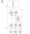
- Fig. 1 is a block diagram showing an example of a system configuration of a vehicle speed estimation system 10 according to the first embodiment.
- the vehicle speed estimation system 10 includes a wheel speed sensor 50, a Global Navigation Satellite System (GNSS) receiver 60, a vehicle speed estimation device 100, and a position calculation device 200.
- GNSS Global Navigation Satellite System
- the wheel speed sensor 50 is mounted on the vehicle and detects the number of pulses generated by the rotation of the tires per unit time. The detected number of pulses is then passed to the first vehicle speed calculation unit 110.
- the vehicle speed estimation device 100 is a device that estimates the speed of a vehicle.
- the vehicle speed estimation device 100 is mounted on the vehicle that estimates the vehicle speed. Note that the vehicle speed estimation device 100 is not limited to being entirely mounted on the vehicle that estimates the vehicle speed, and some of the components of the vehicle speed estimation device 100 may be provided in another device that is connected to the vehicle via a network (not shown).
- the position calculation device 200 is a device that calculates the position of the vehicle based on the vehicle speed estimated by the vehicle speed estimation device 100.
- the position calculation device 200 is mounted on the vehicle whose position is to be calculated.
- the position calculation device 200 is not limited to being mounted on the vehicle, but may be provided on another device connected to the vehicle via a network (not shown).
- the position calculation device 200 is not limited to being provided as a device separate from the vehicle speed estimation device 100, but the vehicle speed estimation device 100 may have its functions.
- the vehicle speed estimation device 100 and the position calculation device 200 shown in FIG. 1 can be configured as a computer including a CPU, a RAM, and a ROM that stores programs and various data for executing each processing routine described below. Since the vehicle speed estimation device 100 and the position calculation device 200 are basically general computer configurations, the vehicle speed estimation device 100 will be described as a representative example.
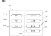
- FIG. 2 is a block diagram showing the hardware configuration of the vehicle speed estimation device 100.
- the vehicle speed estimation device 100 has a CPU (Central Processing Unit) 101, a ROM (Read Only Memory) 102, a RAM (Random Access Memory) 103, a storage 104, an input unit 105, a display unit 106, and a communication unit 107.
- a CPU Central Processing Unit
- ROM Read Only Memory
- RAM Random Access Memory
- CPU 101 is a central processing unit that executes various programs and controls each part. That is, CPU 101 reads programs from ROM 102 or storage 104, and executes the programs using RAM 103 as a working area. CPU 101 controls each of the above components and performs various calculation processes according to the programs recorded in ROM 102 or storage 104. In this embodiment, programs are stored in ROM 102 or storage 104.
- ROM 102 stores various programs and various data.
- RAM 103 temporarily stores programs or data as a working area.
- Storage 104 is composed of a HDD (Hard Disk Drive) or SSD (Solid State Drive) and stores various programs including the operating system and various data.
- the input unit 105 includes a pointing device such as a mouse and a keyboard, and is used to perform various input operations.
- the display unit 106 is, for example, a liquid crystal display.
- the display unit 106 displays various information under the control of the CPU 101.
- the display unit 106 may also function as the input unit 105 by employing a touch panel system.
- the communication unit 107 is for communicating with the wheel speed sensor 50, the GNSS receiver 60, the position calculation device 200, etc.
- the vehicle speed estimation device 100 realizes various functions using the above hardware resources.
- the functional configuration realized by the vehicle speed estimation device 100 will be explained using FIG. 1.
- the vehicle speed estimation device 100 functionally includes a first vehicle speed calculation unit 110, a second vehicle speed calculation unit 120, a scale factor estimation unit 130, and a vehicle speed estimation unit 140.
- the second vehicle speed calculation unit 120 calculates the second vehicle speed of the vehicle based on the signal from the positioning satellite received by the GNSS receiver 60.
- the second vehicle speed is also referred to as the "GNSS speed”.
- the calculated GNSS speed is then passed to the scale factor estimation unit 130.
- the GNSS speed calculated based on the signal from the positioning satellite is more accurate than the wheel speed.
- the GNSS speed calculated based on the signal from the positioning satellite is easily affected by the visibility of the positioning satellite from the vehicle and the surrounding environment of the vehicle such as buildings, but the vehicle speed calculated from the Doppler information is known to have a small offset component and high accuracy.
- the scale factor estimation unit 130 estimates a scale factor according to the wheel speed from the relationship between the ratio of the wheel speed to the GNSS speed (GNSS speed/wheel speed: the numerator is the GNSS speed and the denominator is the wheel speed) and the wheel speed. Specifically, the scale factor is estimated by calculating the ratio of the wheel speed to the GNSS speed and correcting the calculated ratio from the relationship with the wheel speed shown in Figure 3.
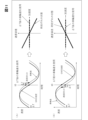
- Figure 3 is an explanatory diagram showing the relationship between the actual vehicle speed and the scale factor for the wheel speed.
- the actual speed in Figure 3 is the correct value of the vehicle speed measured by a measuring instrument.
- the points in Figure 3 are the wheel speeds, and the straight lines are the estimated scale factors.
- the scale factor is estimated from the relationship between the wheel speed and the actual vehicle speed calculated using the least squares method, but is not limited to this.
- a scale factor function is created by converting the slope and the point of contact with the axis into a linear expression.
- the scale factor is then estimated by inputting the wheel speed into this function.
- the scale factor may be estimated by correcting the wheel speed according to the wheel speed taking into account changes in the tire radius, and then calculating the ratio between the wheel speed and the GNSS speed.
- the scale factor function is not limited to a linear expression.
- the tire radius varies depending on the type of tire, air pressure, wear rate, etc., so the scale factor is estimated from the condition of the tires mounted on the vehicle to calculate the vehicle's actual speed.
- the tire radius changes depending on the speed of the vehicle while it is moving due to changes in centrifugal force and temperature (air pressure). Therefore, the faster the speed, the greater the error between the wheel speed and the actual vehicle speed.
- the scale factor designed for a low speed range is continued to be used in a high speed range, the vehicle's position error will continue to occur in the rear direction of the vehicle, and the position error will increase. Therefore, by estimating the scale factor according to the speed of the vehicle while it is moving, it is possible to improve the accuracy of the calculation of the vehicle's actual speed.
- the vehicle speed estimation unit 140 estimates the actual vehicle speed by multiplying the wheel speed by a scale factor.
- the ratio between the wheel speed and the GNSS speed is 1.04.
- the wheel speed scale factor at 25 m/s is, for example, 0.998
- This value becomes the scale factor estimated by the scale factor estimation unit 130.
- the position calculation device 200 calculates the position of the vehicle based on the actual vehicle speed calculated by the vehicle speed estimation device 100. That is, in dead reckoning, which calculates the vehicle speed using the wheel speed, the position calculation device 200 calculates the vehicle's position along the road based on how far the vehicle has traveled at the wheel speed.
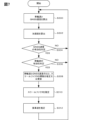
- FIG. 4 is an explanatory diagram showing an example of the flow of operations performed by the CPU 101 of the vehicle speed estimation device 100 of the first embodiment.
- step S100 the first vehicle speed calculation unit 110 calculates the vehicle's wheel speed from the tire pulse count and tire circumference received from the wheel speed sensor 50, and the second vehicle speed calculation unit 120 calculates the vehicle's GNSS speed based on the signal from the positioning satellite received by the GNSS receiver 60. Then, the process proceeds to the next step S102.
- step S102 the second vehicle speed calculation unit 120 determines the validity of the GNSS speed. For example, the accuracy of the GNSS speed is determined from the DOP (Dilution Of Precision) or residual error. If it is determined that the GNSS speed is valid, the process proceeds to the next step S104. On the other hand, if it is not determined that the GNSS speed is valid, the process returns to step S100 described above.
- DOP Deution Of Precision
- step S104 the first vehicle speed calculation unit 110 determines whether the wheel speed is valid. For example, it determines whether the acceleration is equal to or less than a threshold value, or whether the wheel speed is equal to or greater than a threshold value. If the acceleration exceeds the threshold value, or if the wheel speed is less than the threshold value, it does not determine that the wheel speed is valid. If it is determined that the wheel speed is valid, it proceeds to the next step S106. On the other hand, if it is not determined that the wheel speed is valid, it returns to the above-mentioned step S100 again.
- step S106 the ratio between the wheel speed and the GNSS speed and the scale factor function described above are estimated or updated. Then, the process proceeds to the next step S108.
- step S108 the scale factor is estimated from the wheel speed using a scale factor function. Then, the process proceeds to the next step S110.
- step S110 the wheel speed is multiplied by a scale factor to estimate the actual vehicle speed. This process is then repeated.
- This process may be repeated continuously or may be initiated at various times.
- the actual vehicle speed can be calculated with high accuracy by correcting the vehicle speed calculated using the wheel speed sensor 50.
- the actual vehicle speed can be calculated with high accuracy by taking into account the change in tire radius, which varies depending on the vehicle speed. Then, the vehicle position can be calculated based on the calculated actual vehicle speed with high accuracy.
- the scale factor estimating unit 130 estimates a scale factor for each wheel speed, but in the second embodiment, the scale factor estimating unit 130 estimates a scale factor for each speed range. Note that the following description will focus on the differences from the first embodiment described above, and descriptions of overlapping parts will be simplified or omitted.
- the scale factor estimation unit 130 estimates the scale factor for multiple divided speed ranges. For example, although not shown, the speed range is divided into three: a low speed range from 0 m/s to less than 10 m/s, a medium speed range from 10 m/s to less than 20 m/s, and a high speed range from 20 m/s or more. The scale factor estimation unit 130 then estimates the scale factor for one speed in each speed range. Here, one speed includes the center point of each speed range, etc. The scale factors for each speed range are connected by an approximation line, and a scale factor function is created based on the approximation line. This makes it possible to estimate the scale factor from various wheel speeds. Note that the speed range is not limited to being divided into three, and may be two or more.
- FIG. 5 is an explanatory diagram showing an example of the flow of operations performed by the CPU 101 of the vehicle speed estimation device 100 of the second embodiment.
- step S200 the first vehicle speed calculation unit 110 calculates the vehicle's wheel speed from the tire pulse count and tire circumference received from the wheel speed sensor 50, and the second vehicle speed calculation unit 120 calculates the vehicle's GNSS speed based on the signal from the positioning satellite received by the GNSS receiver 60. Then, the process proceeds to the next step S202.
- step S202 the second vehicle speed calculation unit 120 determines the validity of the GNSS speed. For example, the accuracy of the GNSS speed is determined from the DOP (Dilution Of Precision) or residual error. If it is determined that the GNSS speed is valid, the process proceeds to the next step S204. On the other hand, if it is not determined that the GNSS speed is valid, the process returns to step S200 described above.
- DOP Deution Of Precision
- step S204 the first vehicle speed calculation unit 110 determines whether the wheel speed is valid. For example, it determines whether the acceleration is equal to or less than a threshold value, or whether the wheel speed is equal to or greater than a threshold value. If the acceleration exceeds the threshold value, or if the wheel speed is less than the threshold value, it does not determine that the wheel speed is valid. If it is determined that the wheel speed is valid, it proceeds to the next step S206. On the other hand, if it is not determined that the wheel speed is valid, it returns to the above-mentioned step S200 again.
- step S206 the process branches to low speed range, medium speed range, or high speed range for each wheel speed calculated in step S200 described above. Then, the process proceeds to step S208, step S210, or step S212, respectively.
- step S208, S210, and S212 the ratio between the wheel speed and the GNSS speed is estimated or updated. Then, the process proceeds to the next step, S214.
- step S214 the scale factor function is estimated or updated. Then, the process proceeds to the next step S216.
- step S216 the scale factor is estimated from the wheel speed using a scale factor function. Then, the process proceeds to the next step S218.
- step S218 the wheel speed is multiplied by the scale factor to estimate the actual vehicle speed. This process is then repeated.
- the scale factor estimation unit 130 does not take into account the vehicle acceleration (longitudinal acceleration) when estimating the scale factor, but the third embodiment differs in that the scale factor estimation unit 130 estimates the scale factor taking acceleration into account. Note that the following description will focus on the differences from the first embodiment described above, and descriptions of overlapping parts will be simplified or omitted.
- the vehicle speed estimation device 100 functionally includes an acceleration calculation unit 150, as shown in FIG. 6.
- the acceleration calculation unit 150 calculates the acceleration (longitudinal acceleration) from the wheel speed.
- the acceleration is calculated using known techniques. For example, the acceleration is calculated by estimating the slope of the speed change from the time difference of the wheel speed or time series data.
- the scale factor estimation unit 130 estimates a scale factor according to the wheel speed from the ratio of the wheel speed to the GNSS speed and the relationship between the wheel speed and acceleration.
- the wheel speed error has a negative correlation in proportion to the acceleration. In other words, as the acceleration increases, the error increases. Also, the error changes in proportion to the wheel speed. In other words, the scale factor estimation unit 130 estimates the wheel speed error using the following formula. Then, the scale factor is estimated using the corrected wheel speed after correcting the error caused by acceleration.
- V1 is the vehicle speed pulse speed before correction
- x is the acceleration of the vehicle
- ⁇ is a coefficient
- e is an estimate of the error in the wheel speed
- ⁇ e is an estimate of the coefficient ⁇ .
- the estimate ⁇ e is estimated, for example, by applying the least squares method to the formula (1). By using the least squares method, the processing time for obtaining the estimate ⁇ e can be shortened.
- the corrected wheel speed is calculated by subtracting the estimated error value from the wheel speed.
- FIG. 7 is an explanatory diagram showing an example of the operation flow of the vehicle speed estimation device 100 of the third embodiment.
- step S300 the first vehicle speed calculation unit 110 calculates the vehicle's wheel speed from the tire pulse count and tire circumference received from the wheel speed sensor 50, and the second vehicle speed calculation unit 120 calculates the vehicle's GNSS speed based on the signal from the positioning satellite received by the GNSS receiver 60. Then, the process proceeds to the next step S302.
- step S302 the acceleration calculation unit 150 calculates the acceleration from the wheel speed. Then, the process proceeds to the next step S304.
- step S304 the second vehicle speed calculation unit 120 determines the validity of the GNSS speed. For example, the accuracy of the GNSS speed is determined from the DOP (Dilution Of Precision) or residual error. If it is determined that the GNSS speed is valid, the process proceeds to the next step S306. On the other hand, if it is not determined that the GNSS speed is valid, the process returns to step S300 described above.
- DOP Deution Of Precision
- step S306 the first vehicle speed calculation unit 110 determines whether the wheel speed is valid. For example, it determines whether the acceleration is equal to or less than a threshold value, or whether the wheel speed is equal to or greater than a threshold value. If the acceleration exceeds the threshold value, or if the wheel speed is less than the threshold value, it does not determine that the wheel speed is valid. If it is determined that the wheel speed is valid, it proceeds to the next step S308. On the other hand, if it is not determined that the wheel speed is valid, it returns to the above-mentioned step S300 again.
- step S308 the ratio between the wheel speed and the GNSS speed and the scale factor function described above are estimated or updated. Then, the process proceeds to the next step S310.
- step S310 the scale factor is estimated from the wheel speed using a scale factor function. Then, the process proceeds to the next step S312.
- step S312 the wheel speed is multiplied by the scale factor to estimate the actual vehicle speed. This process is then repeated.
- the fourth embodiment will be described with reference to Fig. 8.
- the acceleration calculation unit 150 estimates the acceleration, but the fourth embodiment is different in that the acceleration is calculated using an acceleration sensor. Note that the following description will focus on the differences from the first embodiment described above, and descriptions of overlapping parts will be simplified or omitted.
- the vehicle speed estimation system 10 further includes an acceleration sensor 70.
- the acceleration sensor 70 is mounted on the vehicle and detects the acceleration (longitudinal acceleration) of the vehicle. The detected acceleration is then passed to the acceleration calculation unit 150.
- the acceleration calculation unit 150 acquires the acceleration (forward/backward acceleration) detected by the acceleration sensor 70.
- the scale factor estimation unit 130 estimates a scale factor according to the wheel speed from the ratio of the wheel speed to the GNSS speed and the relationship between the wheel speed and the acceleration, as in the third embodiment described above.
- the scale factor is estimated taking into account the acceleration, but in the fifth embodiment, when the acceleration is equal to or less than a threshold value, the scale factor is estimated to estimate the actual vehicle speed in the same manner as in the first embodiment, but when the acceleration exceeds the threshold value, the actual vehicle speed is estimated from the speed change due to the acceleration without using the scale factor.
- the following description will focus on the differences from the above-mentioned embodiments, and descriptions of the overlapping parts will be simplified or omitted.
- the vehicle speed estimation device 100 functionally includes a speed change calculation unit 160, as shown in FIG. 9.
- the speed change calculation unit 160 calculates the speed change amount, which is the amount of change in speed, by integrating the acceleration.
- the scale factor estimation unit 130 estimates a scale factor according to the wheel speed from the relationship between the ratio of the wheel speed to the GNSS speed and the wheel speed, as in the first embodiment described above. In other words, when the acceleration is small, the scale factor is estimated while ignoring the acceleration, and when the acceleration is large, the scale factor is not estimated.
- the acceleration threshold value it is desirable for the acceleration threshold value to be a value small enough to be considered as roughly constant speed driving.
- the vehicle speed estimation unit 140 estimates the actual vehicle speed based on a scale factor corresponding to the wheel speed estimated by the scale factor estimation unit 130. In other words, when the acceleration is negligibly small, the actual vehicle speed is estimated using a scale factor, as in the first embodiment.
- the vehicle speed estimation unit 140 estimates the actual vehicle speed by adding the speed change based on the acceleration to the wheel speed.
- the actual vehicle speed estimated based on the scale factor when the acceleration exceeds the threshold value is used as the initial value, and the vehicle speed is estimated by adding the speed change.
- the sixth embodiment when the acceleration is equal to or less than a threshold value, the actual vehicle speed is estimated by estimating a scale factor taking the speed into consideration as in the first embodiment, but when the acceleration exceeds the threshold value, the magnitude of the time difference between the wheel speed and the GNSS speed is estimated, and the time for referring to the wheel speed is corrected.
- This embodiment is different from the above-mentioned embodiments in that the following description will be focused on the differences from the above-mentioned embodiments, and the description of the overlapping parts will be simplified or omitted.
- the vehicle speed estimation device 100 functionally includes a time lag calculation unit 170, as shown in FIG. 10.
- the time offset calculation unit 170 calculates the amount of time offset between the wheel speed and the GNSS speed from the difference between the wheel speed and the GNSS speed, corrected by a scale factor according to the speed with respect to the acceleration.
- the scale factor estimation unit 130 is the same as in the fifth embodiment.
- the vehicle speed estimation unit 140 estimates the actual vehicle speed based on the scale factor corresponding to the wheel speed estimated by the scale factor estimation unit 130. Also, as shown in FIG. 11, the actual vehicle speed is output as the vehicle speed at time t0 by shifting the time for referencing the wheel speed by an amount corresponding to the time offset estimated by the time offset calculation unit 170.
- Figure 11 shows the relationship of the speed error to acceleration when there is a time lag between the wheel speed corrected by a scale factor according to the speed and the GNSS speed.
- Figure 11 (A) shows the case when the wheel speed is delayed
- Figure 11 (B) shows the case when the wheel speed is advanced.
- the speed error is ⁇ T x.
- the sign of ⁇ T changes depending on whether the time lag is advanced or delayed, and the slope of the speed error is proportional to ⁇ T (see the solid lines in the right diagrams of Figure 11 (A) and 11 (B)).
- the magnitude of the time shift ⁇ T is calculated in the following procedure.
- the scale factor estimation unit 130 estimates a scale factor according to the speed only when the acceleration is equal to or less than a threshold value, as in the fifth embodiment described above.
- the time shift calculation unit 170 observes whether the speed error or scale factor changes to positive or negative when the acceleration exceeds the threshold value, and finds the slope with respect to the acceleration by applying the least squares method. This slope is the magnitude of the time shift ⁇ T. Furthermore, whether the slope is positive or negative corresponds to an advance or delay in the time shift.
- the sixth embodiment differs in that the magnitude of the time shift ⁇ T is calculated and the time shift is corrected, thereby reducing the error that depends on acceleration.
- the time of the currently referenced GNSS speed is shown as t0, and this is the case when the time of the wheel speed is shifted by ⁇ T.
- the wheel speed is delayed, so in order to obtain the speed at the same time as the GNSS speed at time t0, the wheel speed ⁇ T later can be referenced as the wheel speed at time t0.
- the wheel speed is advanced, so the wheel speed ⁇ T earlier can be referenced as the wheel speed at time t0.
- the acceleration is integrated over the time interval in which the reference time is shifted and added to the original wheel speed, the same effect as shifting the reference time can be obtained.
- the time for which the wheel speed is referenced can be directly shifted, or the vehicle speed can be estimated by adding the amount of speed change obtained by integrating the acceleration during the time interval of the time difference, and the same effect can be obtained.
- the vehicle speed estimation device 100 and the position calculation device 200 according to the embodiment have been described above as examples.
- the embodiment may be in the form of a program for causing a computer to execute the functions of each unit of the vehicle speed estimation device 100 and the position calculation device 200.
- the embodiment may be in the form of a non-transitory storage medium that stores these programs and is readable by a computer.
- the processing according to the embodiment is realized by a software configuration using a computer by executing a program, but this is not limited to this.
- the embodiment may be realized, for example, by a hardware configuration or a combination of a hardware configuration and a software configuration.
Landscapes
- Physics & Mathematics (AREA)
- General Physics & Mathematics (AREA)
- Engineering & Computer Science (AREA)
- Radar, Positioning & Navigation (AREA)
- Remote Sensing (AREA)
- Computer Networks & Wireless Communication (AREA)
- Navigation (AREA)
- Regulating Braking Force (AREA)
Priority Applications (2)
| Application Number | Priority Date | Filing Date | Title |
|---|---|---|---|
| CN202480014403.3A CN120752540A (zh) | 2023-03-24 | 2024-03-20 | 车速推定装置、位置计算装置以及程序 |
| US19/317,337 US20250389750A1 (en) | 2023-03-24 | 2025-09-03 | Vehicle speed estimation device, position calculation device, and storage medium storing program |
Applications Claiming Priority (2)
| Application Number | Priority Date | Filing Date | Title |
|---|---|---|---|
| JP2023049068A JP7770353B2 (ja) | 2023-03-24 | 2023-03-24 | 車速推定装置、位置算出装置及びプログラム |
| JP2023-049068 | 2023-03-24 |
Related Child Applications (1)
| Application Number | Title | Priority Date | Filing Date |
|---|---|---|---|
| US19/317,337 Continuation US20250389750A1 (en) | 2023-03-24 | 2025-09-03 | Vehicle speed estimation device, position calculation device, and storage medium storing program |
Publications (1)
| Publication Number | Publication Date |
|---|---|
| WO2024203667A1 true WO2024203667A1 (ja) | 2024-10-03 |
Family
ID=92904893
Family Applications (1)
| Application Number | Title | Priority Date | Filing Date |
|---|---|---|---|
| PCT/JP2024/010881 Ceased WO2024203667A1 (ja) | 2023-03-24 | 2024-03-20 | 車速推定装置、位置算出装置及びプログラム |
Country Status (4)
| Country | Link |
|---|---|
| US (1) | US20250389750A1 (https=) |
| JP (1) | JP7770353B2 (https=) |
| CN (1) | CN120752540A (https=) |
| WO (1) | WO2024203667A1 (https=) |
Cited By (1)
| Publication number | Priority date | Publication date | Assignee | Title |
|---|---|---|---|---|
| CN120526606A (zh) * | 2025-07-23 | 2025-08-22 | 吉林大学 | 基于数据融合和滤波算法的车速估计方法及系统 |
Citations (7)
| Publication number | Priority date | Publication date | Assignee | Title |
|---|---|---|---|---|
| JPH11173870A (ja) * | 1997-12-10 | 1999-07-02 | Matsushita Electric Ind Co Ltd | 走行距離検出装置 |
| JP2002002240A (ja) * | 2000-06-20 | 2002-01-08 | Kenwood Corp | 車両の走行状態監視装置 |
| JP2011059065A (ja) * | 2009-09-14 | 2011-03-24 | Sony Corp | 速度算出装置、速度算出方法及びナビゲーション装置 |
| JP2016109479A (ja) * | 2014-12-03 | 2016-06-20 | 古野電気株式会社 | 車速演算装置および車速演算方法 |
| JP2017147825A (ja) * | 2016-02-16 | 2017-08-24 | 株式会社東芝 | 列車速度位置算出装置、列車運転支援装置、および列車運転制御装置 |
| JP2019203732A (ja) * | 2018-05-22 | 2019-11-28 | 株式会社小野測器 | 状態計測装置 |
| US20200132192A1 (en) * | 2018-10-24 | 2020-04-30 | Hyundai Motor Company | System and method for estimating wheel speed of vehicle |
-
2023
- 2023-03-24 JP JP2023049068A patent/JP7770353B2/ja active Active
-
2024
- 2024-03-20 WO PCT/JP2024/010881 patent/WO2024203667A1/ja not_active Ceased
- 2024-03-20 CN CN202480014403.3A patent/CN120752540A/zh active Pending
-
2025
- 2025-09-03 US US19/317,337 patent/US20250389750A1/en active Pending
Patent Citations (7)
| Publication number | Priority date | Publication date | Assignee | Title |
|---|---|---|---|---|
| JPH11173870A (ja) * | 1997-12-10 | 1999-07-02 | Matsushita Electric Ind Co Ltd | 走行距離検出装置 |
| JP2002002240A (ja) * | 2000-06-20 | 2002-01-08 | Kenwood Corp | 車両の走行状態監視装置 |
| JP2011059065A (ja) * | 2009-09-14 | 2011-03-24 | Sony Corp | 速度算出装置、速度算出方法及びナビゲーション装置 |
| JP2016109479A (ja) * | 2014-12-03 | 2016-06-20 | 古野電気株式会社 | 車速演算装置および車速演算方法 |
| JP2017147825A (ja) * | 2016-02-16 | 2017-08-24 | 株式会社東芝 | 列車速度位置算出装置、列車運転支援装置、および列車運転制御装置 |
| JP2019203732A (ja) * | 2018-05-22 | 2019-11-28 | 株式会社小野測器 | 状態計測装置 |
| US20200132192A1 (en) * | 2018-10-24 | 2020-04-30 | Hyundai Motor Company | System and method for estimating wheel speed of vehicle |
Cited By (1)
| Publication number | Priority date | Publication date | Assignee | Title |
|---|---|---|---|---|
| CN120526606A (zh) * | 2025-07-23 | 2025-08-22 | 吉林大学 | 基于数据融合和滤波算法的车速估计方法及系统 |
Also Published As
| Publication number | Publication date |
|---|---|
| CN120752540A (zh) | 2025-10-03 |
| US20250389750A1 (en) | 2025-12-25 |
| JP2024137521A (ja) | 2024-10-07 |
| JP7770353B2 (ja) | 2025-11-14 |
Similar Documents
| Publication | Publication Date | Title |
|---|---|---|
| JP5460148B2 (ja) | 測位装置及びプログラム | |
| EP2400268B1 (en) | Track information generating device, track information generating method, and computer-readable storage medium | |
| EP1837627B1 (en) | Methods and systems for implementing an iterated extended kalman filter within a navigation system | |
| EP2180292B1 (en) | Apparatus and method for correcting the output signal of an angular velocity sensor | |
| EP2519803B1 (en) | Technique for calibrating dead reckoning positioning data | |
| US11079494B2 (en) | Positioning device | |
| EP2023084A2 (en) | Position correction apparatus | |
| EP2169351B1 (en) | Apparatus and method for correcting an angular velocity sensor. | |
| US20150153460A1 (en) | Sequential Estimation in a Real-Time Positioning or Navigation System Using Historical States | |
| US6766247B2 (en) | Position determination method and navigation device | |
| KR101177374B1 (ko) | 상호작용 다중모델 필터를 이용한 차량 위치 추정방법 | |
| US20250389750A1 (en) | Vehicle speed estimation device, position calculation device, and storage medium storing program | |
| US11280917B2 (en) | Information processing system, storage medium storing information processing program, and control method | |
| JP3218876B2 (ja) | 車両用現在位置検出装置 | |
| US10723360B2 (en) | Apparatus and method for estimating radius of curvature of vehicle | |
| JP5686703B2 (ja) | 移動体回転半径測定装置及び方法 | |
| JP2019184566A (ja) | 車両および車両位置推定装置 | |
| JP6248559B2 (ja) | 車両用走行軌跡算出装置 | |
| US9605958B2 (en) | Method and device for determining the inclined position of a vehicle | |
| KR102734826B1 (ko) | 차량 속도 추정 장치 및 방법 | |
| CA3284823A1 (en) | Vehicle speed estimation device, position calculation device, and program | |
| JP7523861B2 (ja) | 測位装置 | |
| JP3169213B2 (ja) | 移動速度検出方法及び装置、車両のすべり角検出装置 | |
| JP5753026B2 (ja) | 移動体横流れ量計測装置及び方法 | |
| JP2007108071A (ja) | 車載装置 |
Legal Events
| Date | Code | Title | Description |
|---|---|---|---|
| 121 | Ep: the epo has been informed by wipo that ep was designated in this application |
Ref document number: 24779790 Country of ref document: EP Kind code of ref document: A1 |
|
| WWE | Wipo information: entry into national phase |
Ref document number: 202480014403.3 Country of ref document: CN |
|
| WWP | Wipo information: published in national office |
Ref document number: 202480014403.3 Country of ref document: CN |
|
| NENP | Non-entry into the national phase |
Ref country code: DE |
|
| 122 | Ep: pct application non-entry in european phase |
Ref document number: 24779790 Country of ref document: EP Kind code of ref document: A1 |