WO2024203642A1 - 眼科装置、および眼科装置制御プログラム - Google Patents
眼科装置、および眼科装置制御プログラム Download PDFInfo
- Publication number
- WO2024203642A1 WO2024203642A1 PCT/JP2024/010814 JP2024010814W WO2024203642A1 WO 2024203642 A1 WO2024203642 A1 WO 2024203642A1 JP 2024010814 W JP2024010814 W JP 2024010814W WO 2024203642 A1 WO2024203642 A1 WO 2024203642A1
- Authority
- WO
- WIPO (PCT)
- Prior art keywords
- measurement
- image
- eye
- reflected light
- ophthalmic device
- Prior art date
- Legal status (The legal status is an assumption and is not a legal conclusion. Google has not performed a legal analysis and makes no representation as to the accuracy of the status listed.)
- Ceased
Links
Images




Classifications
-
- A—HUMAN NECESSITIES
- A61—MEDICAL OR VETERINARY SCIENCE; HYGIENE
- A61B—DIAGNOSIS; SURGERY; IDENTIFICATION
- A61B3/00—Apparatus for testing the eyes; Instruments for examining the eyes
- A61B3/10—Objective types, i.e. instruments for examining the eyes independent of the patients' perceptions or reactions
- A61B3/103—Objective types, i.e. instruments for examining the eyes independent of the patients' perceptions or reactions for determining refraction, e.g. refractometers, skiascopes
-
- A—HUMAN NECESSITIES
- A61—MEDICAL OR VETERINARY SCIENCE; HYGIENE
- A61B—DIAGNOSIS; SURGERY; IDENTIFICATION
- A61B3/00—Apparatus for testing the eyes; Instruments for examining the eyes
- A61B3/10—Objective types, i.e. instruments for examining the eyes independent of the patients' perceptions or reactions
- A61B3/103—Objective types, i.e. instruments for examining the eyes independent of the patients' perceptions or reactions for determining refraction, e.g. refractometers, skiascopes
- A61B3/1035—Objective types, i.e. instruments for examining the eyes independent of the patients' perceptions or reactions for determining refraction, e.g. refractometers, skiascopes for measuring astigmatism
Definitions
- the present disclosure relates to an ophthalmic device that measures the ocular characteristics of a subject's eye, and an ophthalmic device control program.
- an ocular refraction measuring device or a wavefront aberration measuring device that measures the ocular characteristics of a test eye by irradiating the test eye with measurement light and detecting the fundus reflection.
- the intermediate light-projecting body e.g., the cornea, vitreous body, or crystalline lens
- opacity e.g., cataracts
- the technical objective of this disclosure is to provide an ophthalmic device and an ophthalmic device control program that can effectively detect fundus reflected light.
- the present disclosure is characterized by having the following configuration.
- An ophthalmic device for measuring ocular characteristics of a test eye comprising: a measurement optical system having a measurement light source and an image sensor, which measures the ocular characteristics by capturing a pattern image of fundus reflected light of measurement light emitted from the measurement light source with the image sensor; a focus adjustment means for moving a focus position of the image sensor in the optical axis direction of the image sensor; and a control means for controlling the focus adjustment means to move the focus position when the pattern image is not detected from the measurement image acquired by the image sensor.
- An ophthalmic device control program executed in an ophthalmic device that measures ocular characteristics of a test eye characterized in that, when executed by a control means of the ophthalmic device, the program causes the ophthalmic device to execute a measurement step of measuring the ocular characteristics by capturing, as a pattern image, fundus reflected light of measurement light emitted from a measurement light source using an image sensor, and, if the pattern image is not detected from the measurement image acquired by the image sensor, a focus adjustment step of moving the focus position of the image sensor in the optical axis direction of the image sensor.
- fundus reflected light can be detected effectively.
- FIG. 1 is a diagram showing the external configuration of the present embodiment.
- FIG. 2 is a diagram showing the internal configuration of the present embodiment.
- FIG. 2 is a diagram illustrating a control system of the present embodiment.
- 4 is a flowchart showing a control operation of the present embodiment.
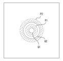
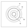
- FIG. 13 is a diagram showing a measurement image in this embodiment.
- FIG. 13 is a diagram showing a measurement image in this embodiment.
- FIG. 13 is a diagram showing a measurement image in this embodiment.
- FIG. 13 is a diagram showing a measurement image in this embodiment.
- FIG. 13 is a diagram showing a measurement image in this embodiment.
- the ophthalmic device of this embodiment measures the ocular refractive power of a subject.
- the ophthalmic device 1 includes a base 2, a measurement unit 3, a face support unit 4, a display unit 75, an operation unit 76, a drive unit 5, and a control unit 70.
- the base 2 supports the measurement unit 3.
- the measurement unit 3 includes an optical system used to measure the subject's eye.
- the face support unit 4 is used to fix the subject's face in front of the measurement unit 3.
- the face support unit 4 is fixed to the base 2 and supports the subject's face.
- the drive unit 5 moves the measurement unit 3 three-dimensionally relative to the base 2.
- the display unit 75 displays the ocular refractive power of the subject's eye on a screen.
- the display unit 75 may function as a touch panel that also serves as an operation unit.
- the operation unit 76 accepts operations from the examiner.
- the optical system provided in the measurement unit 3 will be described with reference to Fig. 2.
- the measurement unit 3 includes, for example, a measurement optical system 100, a fixation target optical system 130, an observation optical system 150, and an index optical system 160. It also includes half mirrors 116 and 117 that branch and combine the optical paths of each optical system, an objective lens 118, a focus adjustment unit 125 that drives some of the optical systems, and a fixation target adjustment unit 135.
- the light source side is upstream and the test eye side is downstream.
- the measurement optical system 100 is used to objectively measure the ocular refractive power of the subject's eye E. For example, the following values are acquired as the measurement results of the ocular refractive power: SPH: spherical power, CYL: cylindrical power, and AXIS: astigmatism axis angle.
- the measurement optical system 100 has a light projecting optical system 100a and a light receiving optical system 100b.
- the light projection optical system 100a has a measurement light source 111 and a relay lens 112, and projects spot-shaped measurement light onto the fundus of the test eye E through the center of the pupil or the corneal apex of the test eye E.
- the measurement light source 111 may be an SLD light source, an LED light source, or another light source. In this embodiment, infrared light is used as the measurement light.
- a prism 115 is placed on the common path of the light projecting optical system 100a and the light receiving optical system 100b.
- the prism 115 is rotated around the optical axis, causing the projected light beam on the pupil to rotate eccentrically at high speed.
- the projected light beam is rotated eccentrically in a region on the pupil of ⁇ 2 mm to ⁇ 4 mm. This region becomes the measurement region for the eye refractive power in this embodiment.
- the light receiving optical system 100b includes a hole mirror 114, a relay lens 120, a light receiving aperture 121, a collimator lens 122, a ring lens 123, and an image sensor 124.
- the light receiving optical system 100b extracts the reflected light beam of the measurement light beam reflected from the fundus in a ring shape through the periphery of the pupil.
- the ring lens 123 is disposed at a pupil conjugate position
- the image sensor 124 is disposed at a fundus conjugate position.
- the ocular refractive power is derived by analyzing the ring image formed on the image sensor 124 via the ring lens 123.
- the ring lens of this embodiment has a lens portion formed in a double concentric circle shape, and the image sensor 124 receives a double ring image.
- the ring lens 123 may be a single ring, or may be three or more rings.
- the measurement light is rotated eccentrically at high speed on the pupil, so that an analysis process is performed on the output image from the image sensor 124 based on an exposure time that is sufficiently long compared to the rotation period, or on an additive image of image data sequentially output from the image sensor 124, to derive the ocular refractive power.
- the values of SPH: spherical power, CYL: cylindrical power, and AXIS: astigmatism axis angle are obtained as the results of the analysis process.
- the measurement light beam from the measurement light source 111 passes through the relay lens 112, the hole of the hole mirror 114, and the prism 115, and is reflected by the half mirror 116 and the half mirror 117, respectively, so that it becomes coaxial with the optical axis L1, and then reaches the fundus via the objective lens 118.
- the reflected light beam from the fundus passes through the optical path that the measurement light beam passed through, is reflected by the mirror of the hole mirror 114, and reaches the image sensor 124 via the ring lens 123.
- the measurement optical system 100 is not limited to the above configuration, and may be configured to project the measurement light into a ring shape onto the test eye, and capture the reflected light as a pattern image with the image sensor 124.
- the focus adjustment unit 125 adjusts the focus position of the measurement optical system 100 (for example, the light receiving optical system 100b) with respect to the test eye E.
- the focus adjustment unit 125 includes a drive unit 126 such as a motor.
- the focus adjustment unit 125 can move the measurement light source 111, the light receiving aperture 121, the collimator lens 122, the ring lens 123, and the image sensor 124 of the measurement optical system 100 together along the optical axis L4.
- the focus adjustment unit 125 can move the measurement light source 111 and the image sensor 124 in fundus conjugate with each other by moving according to the ocular refractive power of the test eye E. For example, when the test eye is farsighted, the image sensor 124, etc.
- the hole mirror 114 and the ring lens 123 are pupil conjugate with a constant magnification.
- the movement position of the focus adjustment unit 125 is detected by a potentiometer, the number of steps of a motor, or the like.
- the fixation target optical system 130 presents a fixation target to the subject's eye E.
- the fixation target is presented on the optical axis of the measurement optical system 100.
- the fixation target optical system 130 is used to fixate the subject's eye E. It is also used to apply fogging and accommodation load to the subject's eye.
- the fixation target optical system 130 includes at least a light source 131 and a fixation target plate 132.
- the fixation target plate 132 may be disposed at a position conjugate with the fundus.
- the fixation light beam from the light source 131 passes through the fixation target plate 132, the lens 133, the lens 134, and the half mirror 116 on the optical axis L2, and is reflected by the half mirror 117 to become coaxial with the optical axis L1.
- the fixation light beam further passes through the objective lens 118 to reach the fundus.
- the fixation target adjustment unit 135 can move the light source 131 and the fixation target plate 132 of the fixation target optical system 130 together along the optical axis.
- the fixation target adjustment unit includes a drive unit 136 such as a motor.
- the fixation target adjustment unit 135 can change the presentation distance of the fixation target plate 132 relative to the subject's eye E (i.e., the presentation position of the fixation target) by moving the drive unit 135 according to the ocular refractive power of the subject's eye E, for example.
- the observation optical system 150 is used to capture a front image of the anterior segment of the subject's eye E.
- the observation optical system 150 includes an image sensor 151 and the like.
- the image sensor 151 may be disposed at a pupil conjugate position.
- An observation image of the anterior segment may be acquired as the front image.
- the observation image is used for alignment and the like.
- an index image point image and Mayer ring image projected onto the cornea from the index projection optical system 160 is captured by the observation optical system 150.
- the index projection optical system 160 is used to align the measurement unit 3 with respect to the subject's eye.
- the index projection optical system 160 includes, for example, a plurality of point light sources 161 and a ring light source 162.
- the point light source 161 projects an infinite index by irradiating the cornea with parallel light.
- the point light source 161 emits infrared light. However, it may be visible light.
- the point light sources 161 are arranged symmetrically in the vertical direction and the horizontal direction with respect to the optical axis L1. For example, in this embodiment, two point light sources are provided on each side. This allows four point image indices to be projected onto the cornea.
- the shape of the indices is not limited to this, and may include linear indices. Also, the number of indices is not limited to this, and may be composed of three or more point image indices.
- the ring light source 162 projects a finite index by irradiating the cornea with diffuse light.
- the ring light source 162 emits infrared light. However, it may be visible light.
- the ring light source 162 is arranged in a ring shape with the optical axis L1 as the center.
- a ring index (so-called Mayer ring) is thereby projected onto the cornea.
- the working distance may be adjusted by moving the measuring unit 3 in the forward/backward direction so that the Purkinje image by the point light source 161 and the Mayer ring image by the ring light source 162 are captured at a predetermined ratio.
- the control unit 70 controls various aspects of the device 1.
- the control unit 70 includes, for example, a general CPU (Central Processing Unit) 71, a ROM 72, a RAM 73, and the like.
- the ROM 72 stores an ophthalmic device control program for controlling the ophthalmic device 1, initial values, and the like.
- the RAM 73 temporarily stores various information.
- the control unit 70 is connected to the light sources, driving units, imaging elements, face support unit 4, driving unit 5, display unit 75, operation unit 76, storage unit (e.g., non-volatile memory) 74, and the like of the measurement unit 3.
- the storage unit 74 is, for example, a non-transient storage medium that can retain the stored contents even if the power supply is cut off.
- a hard disk drive, a flash ROM, a removable USB flash memory, and the like can be used as the storage unit 74.
- Step S1 Alignment
- the control unit 70 starts alignment.
- the control unit 70 starts presenting a fixation target and acquiring an anterior eye image.
- the control unit 70 adjusts the subject's eye E and the ophthalmic device 1 to a predetermined positional relationship based on the observation image of the anterior eye acquired by the observation optical system 150. More specifically, the control unit 70 performs alignment in the XY directions based on the alignment index detected in the observation image so that the optical axis L1 coincides with the corneal apex of the subject's eye E.
- the control unit 70 also performs alignment in the Z direction so that the distance between the subject's eye E and the ophthalmic device 1 is a predetermined working distance.
- Step S2 Preliminary measurement
- the control unit 70 When the alignment is completed, the control unit 70 starts the preliminary measurement.
- the control unit 70 presents a fixation target by arranging the fixation target plate 132 at an initial position that is an optically sufficiently far distance from the subject's eye E and corresponds to the far point of the eye of 0D (diopter).
- the control unit 70 also controls the focus adjustment unit 125 to arrange the focus position of the image sensor 124 (measurement optical system 100) at a position corresponding to 0D, which is the initial position.
- the control unit 70 causes the light source 111 to irradiate the measurement light beam, and causes the image sensor 124 to capture the reflected light beam of the measurement light beam as a ring image.
- the measurement image captured by the image sensor 124 is stored in the storage unit 74 or the like.
- Step S3 Ring image detected
- the control unit 70 judges whether or not a ring image due to fundus reflection light can be detected from the measurement image acquired in the preliminary measurement. For example, the control unit 70 judges whether a ring image can be detected in each meridian direction by performing edge detection processing on the measurement image stored in the storage unit 74.
- the position of the ring image may be detected by cutting the waveform of the luminance signal at a predetermined threshold value and determining the midpoint of the waveform at the cutting position, the peak of the waveform of the luminance signal, the center of gravity position of the luminance signal, or the like. Please refer to JP 2012-075646 A for a method of detecting a ring image.
- the control unit 70 determines that the ring image cannot be detected and proceeds to processing in step S4.
- the control unit 70 determines whether the detected ring image is caused by fundus reflection or internal reflection. In this case, the control unit 70 may determine whether the ring image is caused by fundus reflection or internal reflection based on discrimination information of ring images caused by internal reflection stored in the memory unit 74.
- the discrimination information is, for example, information such as the size, width, edges, chipping, and brightness of the ring image.
- the diopter of the ring image caused by internal reflection may be stored as discrimination information, and a ring image detected at a specific diopter may be determined to be highly likely to be an internal reflection.
- the width W (see FIG. 5B) of the ring image due to internally reflected light is narrower than the fundus reflected light
- the width (number of pixels) of the ring image may be stored as a threshold value as discrimination information, and a ring image whose width is less than the threshold value may be determined to be highly likely to be an internal reflection.
- the shape of the edges of the ring image due to internal reflection can be stored as discrimination information, and ring images with edges above a threshold value can be determined to be highly likely to be due to internal reflection.
- Fundus reflected light may be vignetted by the iris, resulting in a missing ring image (see chip K in Figure 5B), but internally reflected light is not vignetted, so if a ring image is missing, it may be determined that there is a high possibility of a fundus reflection.
- the outer ring is more likely to be missing, so the determination may be made based on the state of the outer ring.
- control unit 70 If the control unit 70 detects a ring image due to internal reflection, it will proceed to step S4 assuming that a ring image due to fundus reflection cannot be detected, but if a ring image due to fundus reflection is detected, it will proceed to processing in step S7.
- Step S4 Focus position adjustment
- the control unit 70 determines that the ring image due to the fundus reflected light cannot be detected from the measurement image, it controls the focus adjustment unit 125 to adjust the focus position of the image pickup element 124 (measurement optical system 100). For example, the control unit 70 adjusts the focus position to any of +5D, -5D, -10D, -15D, and -20D by moving the image pickup element 124 and the measurement light source 111 in the optical axis direction by the focus adjustment unit 125.
- the intervals of the diopters do not have to be 5D, and may be every 1D, every 10D, or any number of D. Also, the intervals do not have to be equal.
- Step S5 Obtaining measurement image
- the control unit 70 acquires a measurement image based on the light reception signal of the image sensor 124.
- the acquired measurement image is stored in the storage unit 74 or the like.
- Step S6 Measurement image analysis
- the control unit 70 analyzes the measurement image acquired after adjusting the focus position.
- the ring image of the fundus reflected light is focused and the possibility of detecting the ring image is increased by adjusting the focus position of the image sensor 124 to a position corresponding to the refractive power of the test eye.
- the focus position is changed to a position of -5D (see FIG. 6A) or to a position of -10D (see FIG. 6B)
- the ring image of the fundus reflected light is focused and easier to detect when the focus position is closer to the refractive power of the test eye.
- the control unit 70 After analyzing the measurement image, the control unit 70 returns to the process of step S3 and determines whether a ring image due to fundus reflected light is detected. The control unit 70 repeats the processes of steps S3 to S6 until a ring image due to fundus reflected light is detected. When repeating the processes of steps S3 to S6, the control unit 70 adjusts the focus adjustment unit 125 to a focus position where no measurement image is acquired. For example, when shifting the focus position every 5D, the focus position is adjusted to a position where no measurement image is acquired, either +5D, -5D, -10D, -15D, or -20D, and a measurement image is acquired. The position of 0D was already acquired during the preliminary measurement in step S2. If a ring image due to fundus reflected light is detected at any focus position, the control unit 70 proceeds to the process of step S7.
- control unit 70 may repeat the processes of steps S4 to S6 multiple times before proceeding to step 3.
- the control unit 70 may also proceed to step S3 after acquiring and analyzing measurement images at all focus positions for each 5D. In such a case, the control unit 70 may compare multiple measurement images to select the measurement image with the highest detection accuracy of a ring image caused by fundus reflected light.
- Step S7 Determine focus position
- the control unit 70 calculates the eye refractive power based on the measurement image in which it has been determined that a ring image can be detected by the preliminary measurement or focus adjustment, and sets the position corresponding to that refractive power as the focus position for the main measurement.
- ocular refractive power For example, if the subject's eye E is an emmetropic eye (i.e., spherical power is 0D), the reflected light beam from the fundus Ef enters the ring lens 123 as a parallel light beam (approximately parallel light beam). As a result, a ring image of the same size as the ring lens 123 is formed on the imaging element 124. On the other hand, if the subject's eye E is a hyperopic eye (e.g., spherical power is +3D, etc.), a ring image enlarged according to the spherical power is formed on the imaging element 124.
- a hyperopic eye e.g., spherical power is +3D, etc.
- the subject's eye E is a myopic eye (e.g., spherical power is -3D, etc.)
- a ring image reduced according to the spherical power is formed on the imaging element 124.
- the subject eye E is an astigmatic eye (e.g., the cylindrical power is -2D and the astigmatism axis angle is 45 degrees, etc.)
- a ring image that is elliptical according to the cylindrical power and tilted according to the astigmatism axis angle is formed on the image sensor 124.
- the control unit 70 thins the image data of the ring image and identifies the position of the ring image in each meridian direction. For example, the position of the ring image may be identified by detecting a luminance signal and determining its peak value, center of gravity position, etc. Next, the control unit 70 approximates the ring image using the least squares method or the like based on the identified position of the ring image, and determines the ocular refractive power in each meridian direction from the shape of the approximated ring image.
- step S4 if the focus position is adjusted to a position other than 0D, the eye refractive power is calculated by adding the adjusted diopter to the diopter obtained by analyzing the ring image. The focus position for this measurement is determined based on the eye refractive power thus obtained.
- Step S8 Main measurement
- the control unit 70 controls the focus adjustment unit 125 to achieve the focus position determined in step S7, and performs the main measurement.
- the control unit 70 may also perform a fogging operation to release the accommodation of the subject's eye.
- the control unit 70 moves the fixation target plate 132 to a fogging start position where the subject's eye E is focused based on the ocular refractive power of the subject's eye E obtained in step S7. This allows the fixation target to be clearly observed by the subject's eye E.
- the control unit 70 moves the fixation target plate 132 to a fogging completion position corresponding to a predetermined amount of fogging. At this time, the fixation target plate 132 is moved in a direction optically farther away (away) from the subject's eye E from the fogging start position toward the fogging completion position.
- fogging of the subject's eye E is completed.
- the ocular refractive power of the subject's eye E approaches the true value from the ocular refractive power obtained in the preliminary measurement, and the adjustment of the subject's eye E is released.
- the control unit 70 calculates the ocular refractive power based on the measurement image acquired under fogging conditions.
- the method of calculating the ocular refractive power is the same as in step S7.
- the control unit 70 calculates the final refractive power of the test eye by summing up the diopter based on the adjustment amount of the focus position and the analysis result of the ring image.
- Step S10 Output of results
- the control unit 70 outputs the measurement result of the eye refractive power in the main measurement to a display unit, a printer, etc.
- the control unit 70 displays the eye refractive power (SPH, CYL, AXIS) of the subject's eye E on the display unit.
- control unit 70 may adjust the light intensity of the measurement light source 111 or the gain of the image sensor 124. This may make it easier to detect the ring image. If the control unit 70 cannot detect a ring image, the control unit 70 may adjust the light intensity of the measurement light source 111 or the gain of the image sensor 124 as a first stage of processing, and if the ring image cannot be detected again, the control unit 70 may control the focus adjustment unit 125 as a second stage of processing to adjust the focus position of the image sensor 124. In this way, the control unit 70 may perform step-by-step control to shorten the measurement time as much as possible.
- the control unit 70 may detect internal reflection in the measurement image by moving the focus adjustment unit 125 to a predetermined position where internal reflection occurs.
- ring images due to internally reflected light may be identified and excluded from detection candidates, making it easier to detect ring images due to other fundus reflected light. For example, if it is known that internal reflection occurs at positions (conjugate positions) corresponding to +25D, +4D, -5D, -16D, and -25D, the focus position may be adjusted to these positions to acquire the measurement image.
- the focus adjustment unit 125 moves the image sensor 124 in the optical axis direction (the direction of the optical axes L1, L3, L4, etc.), this is not limited thereto.
- the focus adjustment unit 125 may be configured to adjust the focus position of the image sensor 124 by inserting and removing an optical element such as a lens onto and from the optical axis of the image sensor 124.
- the ocular refractive power of the test eye is measured by detecting the fundus reflected light from the test eye as a ring image, but it may also be detected as a pattern image of another shape.
- the wavefront aberration of the test eye may be measured by acquiring the fundus reflected light as a Shack-Hartmann image. In this case, too, it is possible to determine whether it is fundus reflected light or internally reflected light based on the brightness or sharpness of the Shack-Hartmann image.
Landscapes
- Life Sciences & Earth Sciences (AREA)
- Health & Medical Sciences (AREA)
- Medical Informatics (AREA)
- Biophysics (AREA)
- Ophthalmology & Optometry (AREA)
- Engineering & Computer Science (AREA)
- Biomedical Technology (AREA)
- Heart & Thoracic Surgery (AREA)
- Physics & Mathematics (AREA)
- Molecular Biology (AREA)
- Surgery (AREA)
- Animal Behavior & Ethology (AREA)
- General Health & Medical Sciences (AREA)
- Public Health (AREA)
- Veterinary Medicine (AREA)
- Eye Examination Apparatus (AREA)
Priority Applications (2)
| Application Number | Priority Date | Filing Date | Title |
|---|---|---|---|
| JP2025510594A JPWO2024203642A1 (https=) | 2023-03-31 | 2024-03-19 | |
| EP24779767.3A EP4691344A1 (en) | 2023-03-31 | 2024-03-19 | Ophthalmic device and ophthalmic device control program |
Applications Claiming Priority (2)
| Application Number | Priority Date | Filing Date | Title |
|---|---|---|---|
| JP2023058641 | 2023-03-31 | ||
| JP2023-058641 | 2023-03-31 |
Publications (1)
| Publication Number | Publication Date |
|---|---|
| WO2024203642A1 true WO2024203642A1 (ja) | 2024-10-03 |
Family
ID=92904809
Family Applications (1)
| Application Number | Title | Priority Date | Filing Date |
|---|---|---|---|
| PCT/JP2024/010814 Ceased WO2024203642A1 (ja) | 2023-03-31 | 2024-03-19 | 眼科装置、および眼科装置制御プログラム |
Country Status (3)
| Country | Link |
|---|---|
| EP (1) | EP4691344A1 (https=) |
| JP (1) | JPWO2024203642A1 (https=) |
| WO (1) | WO2024203642A1 (https=) |
Citations (3)
| Publication number | Priority date | Publication date | Assignee | Title |
|---|---|---|---|---|
| JP2007282671A (ja) | 2006-04-12 | 2007-11-01 | Nidek Co Ltd | 眼科装置 |
| JP2012075646A (ja) | 2010-09-30 | 2012-04-19 | Nidek Co Ltd | 眼屈折力測定装置 |
| JP2021040850A (ja) * | 2019-09-10 | 2021-03-18 | 株式会社トプコン | 眼科装置、及びその制御方法 |
-
2024
- 2024-03-19 JP JP2025510594A patent/JPWO2024203642A1/ja active Pending
- 2024-03-19 WO PCT/JP2024/010814 patent/WO2024203642A1/ja not_active Ceased
- 2024-03-19 EP EP24779767.3A patent/EP4691344A1/en active Pending
Patent Citations (3)
| Publication number | Priority date | Publication date | Assignee | Title |
|---|---|---|---|---|
| JP2007282671A (ja) | 2006-04-12 | 2007-11-01 | Nidek Co Ltd | 眼科装置 |
| JP2012075646A (ja) | 2010-09-30 | 2012-04-19 | Nidek Co Ltd | 眼屈折力測定装置 |
| JP2021040850A (ja) * | 2019-09-10 | 2021-03-18 | 株式会社トプコン | 眼科装置、及びその制御方法 |
Non-Patent Citations (1)
| Title |
|---|
| See also references of EP4691344A1 |
Also Published As
| Publication number | Publication date |
|---|---|
| JPWO2024203642A1 (https=) | 2024-10-03 |
| EP4691344A1 (en) | 2026-02-11 |
Similar Documents
| Publication | Publication Date | Title |
|---|---|---|
| CN102525399B (zh) | 眼测定装置 | |
| US10188282B2 (en) | Subjective optometry apparatus | |
| US12133687B2 (en) | Ophthalmic apparatus | |
| JP6613103B2 (ja) | 眼科装置 | |
| JP7024295B2 (ja) | 自覚式検眼装置 | |
| JPH10108837A (ja) | 眼科測定装置 | |
| JP2017086652A (ja) | 自覚式検眼装置 | |
| JP7459491B2 (ja) | 眼科測定装置 | |
| JP4426837B2 (ja) | 眼調節機能測定装置 | |
| JP6922338B2 (ja) | 自覚式検眼装置 | |
| JP2016220860A (ja) | 眼科測定装置 | |
| JP7608944B2 (ja) | 眼科装置 | |
| JP2018171140A (ja) | 自覚式検眼装置及び自覚式検眼プログラム | |
| JP2018038788A (ja) | 自覚式検眼装置及び自覚式検眼プログラム | |
| JP2017042312A (ja) | 眼科装置 | |
| JP7844996B2 (ja) | 検眼装置 | |
| WO2024203642A1 (ja) | 眼科装置、および眼科装置制御プログラム | |
| JP2020137915A (ja) | 自覚式検眼装置及び自覚式検眼プログラム | |
| JP7480552B2 (ja) | 眼科装置および眼軸長演算プログラム | |
| WO2019069578A1 (ja) | 視覚検査装置 | |
| JP7589625B2 (ja) | 眼科装置 | |
| JP2017086653A (ja) | 自覚式検眼装置 | |
| JP2017086654A (ja) | 自覚式検眼装置及び自覚式検眼プログラム | |
| JP7480553B2 (ja) | 眼科装置 | |
| JP7714897B2 (ja) | 眼科装置及び眼科プログラム |
Legal Events
| Date | Code | Title | Description |
|---|---|---|---|
| 121 | Ep: the epo has been informed by wipo that ep was designated in this application |
Ref document number: 24779767 Country of ref document: EP Kind code of ref document: A1 |
|
| ENP | Entry into the national phase |
Ref document number: 2025510594 Country of ref document: JP Kind code of ref document: A |
|
| WWE | Wipo information: entry into national phase |
Ref document number: 2025510594 Country of ref document: JP |
|
| WWE | Wipo information: entry into national phase |
Ref document number: 2024779767 Country of ref document: EP |
|
| NENP | Non-entry into the national phase |
Ref country code: DE |
|
| ENP | Entry into the national phase |
Ref document number: 2024779767 Country of ref document: EP Effective date: 20251031 |
|
| ENP | Entry into the national phase |
Ref document number: 2024779767 Country of ref document: EP Effective date: 20251031 |
|
| ENP | Entry into the national phase |
Ref document number: 2024779767 Country of ref document: EP Effective date: 20251031 |
|
| ENP | Entry into the national phase |
Ref document number: 2024779767 Country of ref document: EP Effective date: 20251031 |
|
| ENP | Entry into the national phase |
Ref document number: 2024779767 Country of ref document: EP Effective date: 20251031 |
|
| ENP | Entry into the national phase |
Ref document number: 2024779767 Country of ref document: EP Effective date: 20251031 |
|
| ENP | Entry into the national phase |
Ref document number: 2024779767 Country of ref document: EP Effective date: 20251031 |
|
| ENP | Entry into the national phase |
Ref document number: 2024779767 Country of ref document: EP Effective date: 20251031 |
|
| WWP | Wipo information: published in national office |
Ref document number: 2024779767 Country of ref document: EP |