WO2024203102A1 - 送信装置および送信方法、並びに、受信装置および受信方法 - Google Patents
送信装置および送信方法、並びに、受信装置および受信方法 Download PDFInfo
- Publication number
- WO2024203102A1 WO2024203102A1 PCT/JP2024/008689 JP2024008689W WO2024203102A1 WO 2024203102 A1 WO2024203102 A1 WO 2024203102A1 JP 2024008689 W JP2024008689 W JP 2024008689W WO 2024203102 A1 WO2024203102 A1 WO 2024203102A1
- Authority
- WO
- WIPO (PCT)
- Prior art keywords
- signal
- complex
- frame
- time synchronization
- frequency
- Prior art date
- Legal status (The legal status is an assumption and is not a legal conclusion. Google has not performed a legal analysis and makes no representation as to the accuracy of the status listed.)
- Ceased
Links
Images



Classifications
-
- H—ELECTRICITY
- H04—ELECTRIC COMMUNICATION TECHNIQUE
- H04B—TRANSMISSION
- H04B1/00—Details of transmission systems, not covered by a single one of groups H04B3/00 - H04B13/00; Details of transmission systems not characterised by the medium used for transmission
- H04B1/69—Spread spectrum techniques
-
- H—ELECTRICITY
- H04—ELECTRIC COMMUNICATION TECHNIQUE
- H04L—TRANSMISSION OF DIGITAL INFORMATION, e.g. TELEGRAPHIC COMMUNICATION
- H04L27/00—Modulated-carrier systems
-
- H—ELECTRICITY
- H04—ELECTRIC COMMUNICATION TECHNIQUE
- H04L—TRANSMISSION OF DIGITAL INFORMATION, e.g. TELEGRAPHIC COMMUNICATION
- H04L7/00—Arrangements for synchronising receiver with transmitter
Definitions
- This disclosure relates to a transmitting device and a transmitting method, and a receiving device and a receiving method, and in particular to a transmitting device and a transmitting method, and a receiving device and a receiving method that enable more suitable detection of frame positions.
- ELTRES registered trademark
- LPWA Low Power Wide Area
- base stations and terminals achieve time synchronization using the Global Navigation Satellite System (GNSS) to send and receive data frames between each other.
- GNSS Global Navigation Satellite System
- Time synchronization using GNSS has issues such as high power consumption, time required for synchronization depending on the situation, and inability to achieve synchronization indoors.
- the transmitting side transmits a modulated signal that includes a synchronization sequence
- the receiving side detects the frame position by calculating the correlation between the received signal and a known synchronization sequence.
- Patent document 1 discloses a method for generating a transmission signal for estimating a frame position by allocating a modulation signal and a narrowband synchronization signal to two different axes in a complex signal space.
- the transmitting device of the first aspect of the present disclosure is a transmitting device including a modulated signal generating unit that generates a complex modulated signal including a synchronization sequence, a CW signal generating unit that generates a complex CW signal having an arbitrary frequency, a frame generating unit that generates a time synchronization frame for time synchronization with a receiving device by superimposing the complex modulated signal on the complex CW signal, and a transmitting unit that transmits the time synchronization frame as a transmission signal to the receiving device.
- the transmission method is a transmission method in which a transmitting device generates a complex modulated signal including a synchronization sequence, generates a complex CW signal having an arbitrary frequency, superimposes the complex modulated signal on the complex CW signal to generate a time synchronization frame for time synchronization with a receiving device, and transmits the time synchronization frame as a transmission signal to the receiving device.
- the receiving device is a receiving device that includes a frame position detection unit that detects the frame position of a time synchronization frame by detecting the frequency peak of the complex CW signal through frequency analysis of a transmission signal from a transmitting device that generates a time synchronization frame by superimposing a complex CW signal having an arbitrary frequency on a complex modulated signal including a synchronization sequence.
- the receiving method is a receiving method in which a receiving device detects the frame position of a time synchronization frame by detecting the frequency peak of a complex CW signal through frequency analysis of a transmission signal from a transmitting device that generates a time synchronization frame by superimposing a complex CW signal having an arbitrary frequency on a complex modulated signal including a synchronization sequence.
- a complex modulated signal including a synchronization sequence is generated, a complex CW signal having an arbitrary frequency is generated, and a time synchronization frame for time synchronization with a receiving device is generated by superimposing the complex modulated signal on the complex CW signal, and the time synchronization frame is transmitted to the receiving device as a transmission signal.
- a transmitting device generates a time synchronization frame by superimposing a complex CW signal having an arbitrary frequency on a complex modulated signal including a synchronization sequence, and a frequency peak of the complex CW signal is detected by frequency analysis of the transmitted signal, thereby detecting the frame position of the time synchronization frame.
- FIG. 1 is a diagram illustrating an example of the configuration of a wireless communication system to which the technology disclosed herein can be applied.
- FIG. 2 is a block diagram showing a configuration example of a transmission device. 13 is a flowchart illustrating a time synchronization frame generation process.
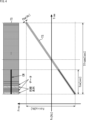
- FIG. 2 is a diagram illustrating a configuration of a transmission signal.
- FIG. 2 is a block diagram showing a configuration example of a receiving device.
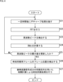
- 11 is a flowchart illustrating a frame position detection process.
- ELTRES registered trademark
- a base station and a terminal realize time synchronization using a Global Navigation Satellite System (GNSS) to transmit and receive data frames to each other.
- GNSS Global Navigation Satellite System
- Time synchronization using the GNSS has problems such as high power consumption, time required for synchronization depending on the situation, and inability to achieve synchronization indoors.
- the transmitting side transmits a modulated signal that includes a synchronization sequence
- the receiving side detects the frame position by calculating the correlation between the received signal and a known synchronization sequence.
- ELTRES (registered trademark) data frames have high sensitivity and interference wave resistance, and the same or better communication performance is required for time synchronization frames. However, if you try to achieve the communication performance required for ELTRES (registered trademark) using the preamble method, the amount of processing becomes enormous, and the receiving terminal requires many calculation circuits.
- a time synchronization frame is generated by superimposing a complex CW signal of any frequency onto a complex modulated signal containing a synchronization sequence, thereby achieving high communication performance and reception processing with a small amount of processing.
- FIG. 1 is a diagram showing an example configuration of a wireless communication system to which the technology according to the present disclosure can be applied.
- a transmitting device 100 as a base station and a receiving device 200 as a terminal device transmit and receive data frames using the ELTRES (registered trademark) method, which is one of the LPWA communication standards.
- ELTRES registered trademark
- the transmitting device 100 acquires time information by receiving GNSS signals from GNSS satellites.
- the transmitting device 100 transmits a time synchronization frame based on the time information to the receiving device 200 using the downlink.
- the receiving device 200 performs time synchronization with the transmitting device 100 by using the time synchronization frame from the transmitting device 100.
- the receiving device 200 can achieve time synchronization with the transmitting device 100 by using a downlink without using GNSS, making it possible to achieve synchronization even indoors or semi-indoors.
- GNSS GNSS chip
- FIG. 2 is a block diagram showing an example of the configuration of the transmitting device 100.
- the transmitting device 100 includes a CW signal generating unit 110, a modulated signal generating unit 120, a transmission signal generating unit 130, and a transmitting unit 140.
- the CW signal generating unit 110 generates a complex CW (Continuous Wave) signal, which is a complex sine wave signal having an arbitrary frequency.
- the frequency of the complex CW signal is, for example, 0 Hz (DC component only), but may be any frequency as long as it does not deviate from the objective of the technology disclosed herein.
- the CW signal generating unit 110 has an amplifier 111, and multiplies the amplitude of the complex CW signal by a predetermined factor as necessary before supplying it to the transmission signal generating unit 130.
- the modulation signal generator 120 generates a complex modulation signal that includes the transmission data and a synchronization sequence.
- an adder 121 In the modulated signal generating unit 120, an adder 121 generates modulated data by evenly distributing a synchronization sequence (synchronization signal) generated, for example, by pseudorandom numbers within the frames that make up the transmission data.
- the modulator 122 generates a complex modulated signal by performing ⁇ /2 BPSK (Binary Phase-Shift Keying) modulation, which is a type of phase shift keying, on the modulated data generated by the adder 121.
- the modulated signal generating unit 120 has an amplifier 123, which multiplies the amplitude of the complex modulated signal by a specified factor as necessary and supplies it to the transmission signal generating unit 130.
- the complex modulated signal generated by the modulated signal generating unit 120 may be composed of only a synchronization sequence, or may be configured to include a synchronization sequence and other data sequences such as transmission data.
- the modulation method for the complex modulated signal is not limited to ⁇ /2 BPSK modulation, and other modulation methods can be adopted as long as they do not deviate from the objective of the technology disclosed herein.
- the transmission signal generating unit 130 functions as a frame generating unit that generates a time synchronization frame for time synchronization with the receiving device 200 by superimposing the complex CW signal from the CW signal generating unit 110 on the complex modulated signal from the modulated signal generating unit 120.
- the superposition unit 131 superposes a complex CW signal on the complex modulated signal.
- the transmission signal generation unit 130 generates a time synchronization frame by superposing a carrier signal on the complex modulated signal on which the complex CW signal is superposed.
- the chirp modulation unit 132 performs chirp modulation processing by using a chirp signal that changes the center frequency linearly over the elapsed time of the frame as the carrier signal.
- the transmission signal generation unit 130 then supplies the time synchronization frame that has been subjected to chirp modulation processing to the transmission unit 140 as a transmission signal.
- the transmitting unit 140 appropriately amplifies the transmission signal from the transmission signal generating unit 130 and transmits it to the receiving device 200.
- step S11 the CW signal generator 110 generates a complex CW signal of an arbitrary frequency.
- step S12 the modulation signal generation unit 120 generates a complex modulation signal including a synchronization sequence.
- step S13 the transmission signal generating unit 130 (superimposing unit 131) generates a time synchronization frame by superimposing the complex CW signal generated by the CW signal generating unit 110 on the complex modulated signal generated by the modulated signal generating unit 120.
- the complex CW signal and the complex modulated signal are both complex signals, the complex CW signal component becomes a single very narrowband signal component in the time synchronization frame.
- step S14 the transmission signal generation unit 130 (chirp modulation unit 132) generates a transmission signal by performing chirp modulation processing on the complex modulated signal on which the complex CW signal is superimposed.
- step S15 the transmitter 140 transmits the transmission signal generated by the transmission signal generator 130.
- Figure 4 shows a time synchronization frame TS as a chirp-modulated transmission signal, with a center frequency of Fc [Hz], a frame period of Tframe [sec], a chirp width of Fchirp [Hz], and a bandwidth of Fbw [Hz].
- the time synchronization frame TS is configured to have a center frequency of Fc in the middle of the frame period Tframe.
- a complex CW signal is superimposed on a complex modulated signal in which a synchronization sequence (synchronization signal) generated by pseudo-random numbers is evenly distributed within the frame that constitutes the transmission data.
- a synchronization sequence synchronization signal
- the complex CW signal and the complex modulated signal are both complex signals, as shown in Figure 4, in the time synchronization frame TS, the transmission power of the complex CW signal component (CW) is concentrated at one specific frequency.
- the complex CW signal may be superimposed (combined) with at least any time domain of the frame period Tframe of the complex modulated signal, as long as it does not deviate from the objective of the technology disclosed herein.
- the complex CW signal may be combined with the entire time domain of the frame period Tframe of the complex modulated signal, or may be combined with a part of that time domain.
- the complex CW signal is combined with the time domain of the period Tcw [sec] from the beginning of the time synchronization frame TS.
- the complex CW signal may be combined without depending on the phase of the complex modulated signal.
- the complex CW signal when the complex CW signal is superimposed on the complex modulated signal, it is not necessary to match the phase of the complex modulated signal.
- a time synchronization frame is generated by superimposing a complex CW signal having an arbitrary frequency on a complex modulated signal including a synchronization sequence, so that the time synchronization frame includes a narrowband synchronization signal in which transmission power is concentrated in one narrow band.
- a performance improvement of about 3 dB can be achieved. This makes it possible to increase noise resistance when performing FFT on the signal received on the receiving side to detect the peak of the narrowband synchronization signal, thereby achieving high communication performance while enabling the receiving side to more appropriately detect the frame position, as described below.
- FIG. 5 is a block diagram showing an example of the configuration of the receiving device 200. As shown in FIG.
- the receiving device 200 of FIG. 5 the configuration from receiving radio waves to converting them into a digital IQ signal is omitted. That is, as shown in FIG. 5, the receiving device 200 includes a first buffer 210, a CW detection unit 220, a peak update unit 230, a storage unit 240, a second buffer 250, and a demodulation unit 260.
- the first buffer 210 stores, as an input signal, a digital IQ signal (a transmission signal from the transmitting device 100) converted from the radio waves received by the receiving device 200.
- the CW detection unit 220 detects the frequency peaks of the complex CW signal from the input signal in the first buffer 210.
- a dechirp processing unit 221 applies dechirp processing to the input signal in the first buffer 210 at regular time intervals, and an LPF (Low Pass Filter) 222 removes high-frequency components.
- An FFT (Fast Fourier Transform) unit 223 performs an FFT on the signal from which the high-frequency components have been removed, and a peak detection unit 224 detects the frequency peaks of the complex CW signal. The detected frequency peaks and the frequency offset contained in the input signal are supplied to a peak update unit 230.
- the peak update unit 230 updates the maximum value of the frequency peak of the complex CW signal based on the frequency peaks detected at regular intervals by the CW detection unit 220.
- the S/N ratio calculation unit 231 calculates the S/N ratio of the analysis result by FFT based on the frequency peak from the CW detection unit 220, and the S/N ratio update unit 232 updates the maximum value of the frequency peak based on the calculated S/N ratio.
- the S/N ratio update unit 232 updates the maximum value of the frequency peak and turns ON, the frequency offset from the CW detection unit 220 is supplied to the storage unit 240.
- the CW detection unit 220 and the peak update unit 230 constitute a frame position detection unit FD that detects the frame position of the time synchronization frame by detecting the frequency peak of the complex CW signal through frequency analysis of the transmission signal from the transmission device 100. This makes it possible to roughly detect the frame position of the time synchronization frame in the transmission signal from the transmission device 100.
- the storage unit 240 stores the input signal when a frequency peak of the complex CW signal is detected in the second buffer 250.
- the maximum value of the frequency peak is updated by the peak update unit 230 and the switch 241 is turned ON, and the input signal in the first buffer 210 is supplied to the dechirp processing unit 242.
- the dechirp processing unit 242 performs dechirp processing on the input signal at regular intervals, and the LPF 243 removes high-frequency components.
- the frequency shift unit 244 corrects the frequency offset from the CW detection unit 220 for the signal from which the high-frequency components have been removed, and the RRC (Root Raised Cosine) filter 245 suppresses inter-symbol interference in the signal from which the frequency offset has been corrected, and supplies the signal to the second buffer 250.
- the demodulation unit 260 performs time synchronization with the transmitting device 100 and demodulation of the transmission data using the input signal stored in the second buffer 250 when a frequency peak of the complex CW signal is detected.
- the demodulation unit 260 is configured to include a synchronization processing unit 310, a fading correction unit 320, a phase correction unit 330, a BPSK demapper 340, and an LDPC unit 350.
- the synchronization processing unit 310 performs time synchronization processing with the transmitting device 100 by performing correlation calculations using the synchronization sequence stored in the second buffer 250 and contained in the input signal (transmission signal) when the frequency peak of the complex CW signal is detected.
- the sample extraction unit 311 extracts the input signal when a frequency peak of the complex CW signal is detected, shifting it by the sample time, and the correlation calculation unit 312 calculates the cross-correlation with a known synchronization sequence.
- the FFT unit 313 performs an FFT on the calculated correlation value
- the peak search unit 314 searches for a peak value from the analysis results by FFT
- the maximum peak selection unit 315 selects the maximum value of the peak values. This makes it possible to detect the frame position of the time synchronization frame with high accuracy in the transmission signal from the transmitting device 100.
- the fading correction unit 320 calculates the amount of correction for the frequency characteristic distortion caused by fading based on the results of the FFT analysis in the synchronization processing unit 310.
- the phase correction unit 330 corrects the phase rotation of the input signal (digital IQ signal) stored in the second buffer 250 based on the amount of correction calculated by the fading correction unit 320.
- the BPSK demapper 340 performs BPSK demodulation by demapping the input signal with the phase rotation corrected, and the LDPC unit 350 performs error correction on the BPSK demodulated data using an LDPC (Low Density Parity Check) code.
- LDPC Low Density Parity Check
- the process in FIG. 6 begins, for example, when the digital IQ signal (input signal) converted from the radio waves received by the receiving device 200 starts to be stored in the first buffer 210.
- step S21 the CW detection unit 220 performs dechirp processing on the input signal in the first buffer 210 at regular intervals, such as every 20 msec.
- step S22 the CW detection unit 220 performs an FFT on the dechirp signal that has been subjected to the dechirp processing.
- step S23 the CW detection unit 220 detects the frequency peaks of the complex CW signal based on the results of the FFT analysis.
- step S24 the peak update unit 230 calculates the S/N ratio of the analysis result by FFT based on the frequency peak detected by the CW detection unit 220. In this way, the S/N ratio calculated for the input signal at regular time intervals is stored in a memory (not shown).
- step S25 the peak update unit 230 compares the calculated S/N ratio with past S/N ratios stored in a memory (not shown) to determine whether the maximum value of the frequency peak of the complex CW signal has been updated.
- step S25 If the maximum frequency peak value has not been updated in step S25, i.e., the calculated SNR is smaller than the previous SNR, the process returns to step S21 and steps S21 to S25 are repeated for the input signal of the next time unit (e.g., 20 msec).
- the next time unit e.g. 20 msec
- step S25 if it is determined in step S25 that the maximum frequency peak has been updated, i.e., if the calculated S/N ratio is greater than the previous S/N ratio, proceed to step S26.
- step S26 the peak update unit 230 detects the frame position of the input signal where the maximum value of the frequency peak of the complex CW signal has been updated as the frame position of the time synchronization frame. This makes it possible to roughly detect the frame position of the time synchronization frame in the transmission signal from the transmitting device 100.
- step S27 the synchronization processing unit 310 performs time synchronization processing by correlation calculation using the synchronization sequence contained in the complex modulation signal component of the input signal when the frame position of the time synchronization frame stored in the second buffer 250 is detected. This makes it possible to detect the frame position of the time synchronization frame with high accuracy in the transmission signal from the transmitting device 100.
- the above process makes it possible to roughly detect the frame position of the time synchronization frame even in an unsynchronized state (a state in which it is unknown when the time synchronization frame will arrive) by detecting the frequency peak of the complex CW signal by FFT of the transmission signal from the transmitting device 100. Then, by performing correlation calculations using the synchronization sequence contained in the complex modulated signal component and the known synchronization sequence, it is possible to detect the frame position of the time synchronization frame with high accuracy.
- the present disclosure can have the following configurations.
- a modulation signal generating unit that generates a complex modulation signal including a synchronization sequence
- a CW signal generating unit that generates a complex CW signal having an arbitrary frequency
- a frame generating unit that generates a time synchronization frame for time synchronization with a receiving device by superimposing the complex CW signal on the complex modulated signal
- a transmitting unit that transmits the time synchronization frame as a transmission signal to the receiving device.
- the transmitting device generating a complex modulated signal including a synchronization sequence; Generate a complex CW signal having an arbitrary frequency; generating a time synchronization frame for time synchronization with a receiving device by superimposing the complex CW signal on the complex modulated signal; a transmission method for transmitting the time synchronization frame as a transmission signal to the receiving device.
- a receiving device comprising: a frame position detection unit that detects a frame position of a time synchronization frame by detecting a frequency peak of a complex CW signal through frequency analysis of a transmission signal from a transmitting device that generates a time synchronization frame by superimposing a complex CW signal having an arbitrary frequency on a complex modulated signal including a synchronization sequence.
- the receiving device (9) The receiving device according to (8), wherein the frame position detection unit detects the time synchronization frame by updating a maximum value of the frequency peak of the complex CW signal through the frequency analysis at regular time intervals. (10) The receiving device according to (9), wherein the frame position detection unit updates a maximum value of the frequency peak of the complex CW signal based on an S/N ratio of an analysis result of the frequency analysis performed at regular intervals. (11) The receiving device according to any one of (8) to (10), further comprising a synchronization processing unit that performs time synchronization processing with the transmitting device by correlation calculation using the synchronization sequence contained in the transmission signal when the frequency peak of the complex CW signal is detected.
- the receiving device A receiving method for detecting a frame position of a time synchronization frame by detecting a frequency peak of a transmission signal from a transmitting device that generates a time synchronization frame by superimposing a complex CW signal having an arbitrary frequency on a complex modulated signal including a synchronization sequence.
- 10 wireless communication system 100 transmitter, 110 CW signal generator, 120 modulation processing generator, 130 transmission signal generator, 140 transmitter, 200 receiver, 220 CW detector, 230 peak updater, FD frame position detector, 240 storage, 260 demodulator, 310 synchronization processor
Landscapes
- Engineering & Computer Science (AREA)
- Computer Networks & Wireless Communication (AREA)
- Signal Processing (AREA)
- Synchronisation In Digital Transmission Systems (AREA)
Priority Applications (1)
| Application Number | Priority Date | Filing Date | Title |
|---|---|---|---|
| JP2025510163A JPWO2024203102A1 (https=) | 2023-03-30 | 2024-03-07 |
Applications Claiming Priority (2)
| Application Number | Priority Date | Filing Date | Title |
|---|---|---|---|
| JP2023055662 | 2023-03-30 | ||
| JP2023-055662 | 2023-03-30 |
Publications (1)
| Publication Number | Publication Date |
|---|---|
| WO2024203102A1 true WO2024203102A1 (ja) | 2024-10-03 |
Family
ID=92905545
Family Applications (1)
| Application Number | Title | Priority Date | Filing Date |
|---|---|---|---|
| PCT/JP2024/008689 Ceased WO2024203102A1 (ja) | 2023-03-30 | 2024-03-07 | 送信装置および送信方法、並びに、受信装置および受信方法 |
Country Status (2)
| Country | Link |
|---|---|
| JP (1) | JPWO2024203102A1 (https=) |
| WO (1) | WO2024203102A1 (https=) |
Citations (2)
| Publication number | Priority date | Publication date | Assignee | Title |
|---|---|---|---|---|
| WO2020175018A1 (ja) * | 2019-02-28 | 2020-09-03 | ソニーセミコンダクタソリューションズ株式会社 | 通信装置、通信方法、通信プログラム、送信装置、及び通信システム |
| WO2022190589A1 (ja) * | 2021-03-08 | 2022-09-15 | ソニーセミコンダクタソリューションズ株式会社 | 受信装置およびその受信方法 |
-
2024
- 2024-03-07 JP JP2025510163A patent/JPWO2024203102A1/ja active Pending
- 2024-03-07 WO PCT/JP2024/008689 patent/WO2024203102A1/ja not_active Ceased
Patent Citations (2)
| Publication number | Priority date | Publication date | Assignee | Title |
|---|---|---|---|---|
| WO2020175018A1 (ja) * | 2019-02-28 | 2020-09-03 | ソニーセミコンダクタソリューションズ株式会社 | 通信装置、通信方法、通信プログラム、送信装置、及び通信システム |
| WO2022190589A1 (ja) * | 2021-03-08 | 2022-09-15 | ソニーセミコンダクタソリューションズ株式会社 | 受信装置およびその受信方法 |
Also Published As
| Publication number | Publication date |
|---|---|
| JPWO2024203102A1 (https=) | 2024-10-03 |
Similar Documents
| Publication | Publication Date | Title |
|---|---|---|
| US5936961A (en) | Signalling packet for communication system with reference modulated in accordance with a time-dependent law | |
| US5809063A (en) | Coherent detection architecture for remote calibration of coherent systems using direct sequence spread spectrum transmission of reference and calibration signals | |
| EP3353969B1 (en) | Frequency tracking with sparse pilots | |
| US6680969B1 (en) | Methods for estimating doppler spreads including autocorrelation function hypotheses and related systems and receivers | |
| EP0884878A2 (en) | Synchronization of frame, symbol clock, and carrier in multicarrier receivers | |
| US6574283B1 (en) | Communication method, transmission and reception apparatuses, and cellular radio communication system | |
| US20100183054A1 (en) | Method for the robust synchronization of a multi-carrier receiver using filter banks and corresponding receiver and transceiver | |
| JP3079950B2 (ja) | 直交周波数分割多重変調信号の受信装置及び伝送方法 | |
| CN1115590A (zh) | 扩频通信接收机 | |
| US9356648B1 (en) | Frequency offset acquisition for wireless communications | |
| US20110075764A1 (en) | Full range offset correction for coherent optical ofdm systems | |
| KR20010041149A (ko) | 주파수 동기 신호를 검출하기 위한 방법 및 장치 | |
| CA2951891C (en) | Blanking using signal-based thresholding schemes | |
| US8208880B2 (en) | Frequency control device, frequency control method, base station apparatus, and mobile station apparatus | |
| JP4659317B2 (ja) | チャンネル自己相関関数仮説を用いるドップラ拡散推定 | |
| US6950456B2 (en) | High-speed cell searching apparatus and method using DPSK-based distributed sample acquisition | |
| US6389040B1 (en) | Apparatus and method for generating a frequency offset estimate for communication systems having frequency selecting fading channels | |
| WO2024203102A1 (ja) | 送信装置および送信方法、並びに、受信装置および受信方法 | |
| JP2001230702A (ja) | スペクトラム拡散通信同期捕捉回路 | |
| US9444671B2 (en) | Antenna direction adjustment method and OFDM reception device | |
| EP1168674A2 (en) | Low signal to noise ratio acquisition and link characterization techniques for VSAT spread spectrum modems | |
| JPH07154129A (ja) | Lms方式のアダプティブアレイアンテナ装置 | |
| Im et al. | Fine Frequency Offset Synchronization Scheme for Internet of Things Devices in 5G non-terrestrial network | |
| US20250338232A1 (en) | Methods for Synchronization in a Non-Terrestrial Network | |
| JP3577104B2 (ja) | データ伝送方法 |
Legal Events
| Date | Code | Title | Description |
|---|---|---|---|
| 121 | Ep: the epo has been informed by wipo that ep was designated in this application |
Ref document number: 24779236 Country of ref document: EP Kind code of ref document: A1 |
|
| ENP | Entry into the national phase |
Ref document number: 2025510163 Country of ref document: JP Kind code of ref document: A |
|
| WWE | Wipo information: entry into national phase |
Ref document number: 2025510163 Country of ref document: JP |
|
| REG | Reference to national code |
Ref country code: BR Ref legal event code: B01A Ref document number: 112025020455 Country of ref document: BR |
|
| NENP | Non-entry into the national phase |
Ref country code: DE |
|
| 122 | Ep: pct application non-entry in european phase |
Ref document number: 24779236 Country of ref document: EP Kind code of ref document: A1 |