WO2024202813A1 - 振動型ジャイロ素子およびジャイロスコープ - Google Patents
振動型ジャイロ素子およびジャイロスコープ Download PDFInfo
- Publication number
- WO2024202813A1 WO2024202813A1 PCT/JP2024/006970 JP2024006970W WO2024202813A1 WO 2024202813 A1 WO2024202813 A1 WO 2024202813A1 JP 2024006970 W JP2024006970 W JP 2024006970W WO 2024202813 A1 WO2024202813 A1 WO 2024202813A1
- Authority
- WO
- WIPO (PCT)
- Prior art keywords
- electrodes
- wiring
- vibrator
- wirings
- primary
- Prior art date
- Legal status (The legal status is an assumption and is not a legal conclusion. Google has not performed a legal analysis and makes no representation as to the accuracy of the status listed.)
- Ceased
Links
Images


Classifications
-
- G—PHYSICS
- G01—MEASURING; TESTING
- G01C—MEASURING DISTANCES, LEVELS OR BEARINGS; SURVEYING; NAVIGATION; GYROSCOPIC INSTRUMENTS; PHOTOGRAMMETRY OR VIDEOGRAMMETRY
- G01C19/00—Gyroscopes; Turn-sensitive devices using vibrating masses; Turn-sensitive devices without moving masses; Measuring angular rate using gyroscopic effects
- G01C19/56—Turn-sensitive devices using vibrating masses, e.g. vibratory angular rate sensors based on Coriolis forces
- G01C19/567—Turn-sensitive devices using vibrating masses, e.g. vibratory angular rate sensors based on Coriolis forces using the phase shift of a vibration node or antinode
- G01C19/5677—Turn-sensitive devices using vibrating masses, e.g. vibratory angular rate sensors based on Coriolis forces using the phase shift of a vibration node or antinode of essentially two-dimensional [2D] vibrators, e.g. ring-shaped vibrators
- G01C19/5684—Turn-sensitive devices using vibrating masses, e.g. vibratory angular rate sensors based on Coriolis forces using the phase shift of a vibration node or antinode of essentially two-dimensional [2D] vibrators, e.g. ring-shaped vibrators the devices involving a micromechanical structure
-
- G—PHYSICS
- G01—MEASURING; TESTING
- G01C—MEASURING DISTANCES, LEVELS OR BEARINGS; SURVEYING; NAVIGATION; GYROSCOPIC INSTRUMENTS; PHOTOGRAMMETRY OR VIDEOGRAMMETRY
- G01C19/00—Gyroscopes; Turn-sensitive devices using vibrating masses; Turn-sensitive devices without moving masses; Measuring angular rate using gyroscopic effects
- G01C19/56—Turn-sensitive devices using vibrating masses, e.g. vibratory angular rate sensors based on Coriolis forces
- G01C19/5607—Turn-sensitive devices using vibrating masses, e.g. vibratory angular rate sensors based on Coriolis forces using vibrating tuning forks
- G01C19/5621—Turn-sensitive devices using vibrating masses, e.g. vibratory angular rate sensors based on Coriolis forces using vibrating tuning forks the devices involving a micromechanical structure
-
- G—PHYSICS
- G01—MEASURING; TESTING
- G01C—MEASURING DISTANCES, LEVELS OR BEARINGS; SURVEYING; NAVIGATION; GYROSCOPIC INSTRUMENTS; PHOTOGRAMMETRY OR VIDEOGRAMMETRY
- G01C19/00—Gyroscopes; Turn-sensitive devices using vibrating masses; Turn-sensitive devices without moving masses; Measuring angular rate using gyroscopic effects
- G01C19/56—Turn-sensitive devices using vibrating masses, e.g. vibratory angular rate sensors based on Coriolis forces
- G01C19/5642—Turn-sensitive devices using vibrating masses, e.g. vibratory angular rate sensors based on Coriolis forces using vibrating bars or beams
-
- G—PHYSICS
- G01—MEASURING; TESTING
- G01C—MEASURING DISTANCES, LEVELS OR BEARINGS; SURVEYING; NAVIGATION; GYROSCOPIC INSTRUMENTS; PHOTOGRAMMETRY OR VIDEOGRAMMETRY
- G01C19/00—Gyroscopes; Turn-sensitive devices using vibrating masses; Turn-sensitive devices without moving masses; Measuring angular rate using gyroscopic effects
- G01C19/56—Turn-sensitive devices using vibrating masses, e.g. vibratory angular rate sensors based on Coriolis forces
- G01C19/5719—Turn-sensitive devices using vibrating masses, e.g. vibratory angular rate sensors based on Coriolis forces using planar vibrating masses driven in a translation vibration along an axis
- G01C19/5726—Signal processing
-
- G—PHYSICS
- G01—MEASURING; TESTING
- G01C—MEASURING DISTANCES, LEVELS OR BEARINGS; SURVEYING; NAVIGATION; GYROSCOPIC INSTRUMENTS; PHOTOGRAMMETRY OR VIDEOGRAMMETRY
- G01C19/00—Gyroscopes; Turn-sensitive devices using vibrating masses; Turn-sensitive devices without moving masses; Measuring angular rate using gyroscopic effects
- G01C19/56—Turn-sensitive devices using vibrating masses, e.g. vibratory angular rate sensors based on Coriolis forces
- G01C19/5776—Signal processing not specific to any of the devices covered by groups G01C19/5607 - G01C19/5719
-
- G—PHYSICS
- G01—MEASURING; TESTING
- G01C—MEASURING DISTANCES, LEVELS OR BEARINGS; SURVEYING; NAVIGATION; GYROSCOPIC INSTRUMENTS; PHOTOGRAMMETRY OR VIDEOGRAMMETRY
- G01C25/00—Manufacturing, calibrating, cleaning, or repairing instruments or devices referred to in the other groups of this subclass
- G01C25/005—Manufacturing, calibrating, cleaning, or repairing instruments or devices referred to in the other groups of this subclass initial alignment, calibration or starting-up of inertial devices
Definitions
- This invention relates to a vibration type gyro element having a vibrator and electrodes, and a gyroscope having the same.
- gyroscopes equipped with a vibration-type gyro element that has a vibrator and electrodes are known. Such a gyroscope is disclosed, for example, in JP 2009-115559 A.
- the angular velocity detected by the gyroscope contains a bias component.
- the bias component is also called zero-point output or offset, and is generated by various factors such as the asymmetry of the vibration-type gyro element and the characteristics of the circuit. Therefore, in the gyroscope described in the above-mentioned Patent Document 1, the primary drive electrode and the secondary drive electrode are swapped, and the primary detection electrode and secondary detection electrode are swapped, and the bias component is cancelled by taking the difference between the output signals of the gyroscope before and after the electrode swap.
- the bias component may not be canceled and remain.
- a bias component is generated due to electrical crosstalk (inflow of unnecessary electrical signals due to electrical coupling) corresponding to the resistance components of the electrodes and the wiring corresponding to the electrodes, but because the resistance components are different before and after the electrode swap, the magnitude of the bias component differs before and after the electrode swap.
- This invention has been made to solve the problems described above, and one object of the invention is to provide a vibration type gyro element and a gyroscope that can fully cancel bias components due to electrical crosstalk corresponding to resistance components in a switching configuration.
- a vibration type gyro element comprises a vibrator, a plurality of electrodes arranged on the vibrator, and a plurality of wirings provided corresponding to the plurality of electrodes, the plurality of electrodes including a primary drive electrode for exciting a primary vibration in the vibrator, a primary detection electrode for detecting the primary vibration, a secondary detection electrode for detecting a secondary vibration of the vibrator, and a secondary drive electrode for driving the vibrator to cancel the secondary vibration, and a switching unit is provided for switching between the primary drive electrode and its wiring and either the secondary drive electrode and its wiring or the secondary detection electrode and its wiring, and switching between the primary detection electrode and its wiring and either the secondary detection electrode and its wiring or the secondary drive electrode and its wiring, and adjusting at least one of the wiring pattern, the number of bonding wires provided on the wiring, and other electrical elements that increase or decrease the electrical resistance, thereby matching the resistance components between the electrodes and their wirings to be switched between the switching unit
- matching the resistance components is a broad term that includes not only the case where the resistance components are completely equal, but also the case where the resistance components are almost equal.
- the area between the switching unit and the vibrator means that it includes all of the electrodes expected to perform the functions of exciting the primary vibration of the vibrator, detecting the primary vibration, detecting the secondary vibration, and canceling the secondary vibration from the switching unit onwards on the vibrator, as well as all of the wiring connected to perform the functions of each electrode, and does not mean only a portion of it.
- the wiring pattern, the number of bonding wires provided in the wiring, and at least one of the other electrical elements that increase or decrease the electrical resistance are adjusted to match the resistance components between the switching unit and the vibrator in the electrodes and their wiring to be swapped.
- This allows the resistance components of the electrodes and their wiring performing each function to be matched before and after the swap, reducing the difference in bias components due to electrical crosstalk corresponding to the resistance components that are superimposed on the output signals before and after the swap.
- This allows the bias components due to electrical crosstalk corresponding to the resistance components to be sufficiently canceled when the output signals before and after the swap are differentiated.
- the detection accuracy of angular velocity can be improved in a gyroscope equipped with a vibration type gyro element.
- the number of bonding wires is preferably made the same for the wirings to be replaced, thereby matching the resistance components between the switching section and the vibrator for the electrodes to be replaced and their wirings.
- the bonding wires have a different thickness from the wirings, and therefore the resistance values are also different. Also, even if the total distance of the wiring is the same, the resistance value can differ only depending on the presence or absence of bonding wires. Therefore, by making the number of bonding wires the same for the wirings to be replaced as described above, the influence of providing bonding wires themselves, which is caused by the thickness, can be suppressed, and the resistance components can be easily matched for the electrodes to be replaced and their wirings. Note that in this specification, making the numbers the same is a concept that also includes making the numbers zero.
- the lengths of the bonding wires it is preferable to make the lengths of the bonding wires the same for the wirings to be swapped, so that the resistance components of the electrodes to be swapped and their wirings between the switching unit and the vibrator are matched. With this configuration, it is easier to match the resistance components of the electrodes to be swapped and their wirings.
- the first bonding wire and the other bonding wire are not parallel to each other or are spaced apart.
- This configuration unlike when the first bonding wire and the other bonding wire are parallel and arranged nearby, makes it possible to prevent mutual induction from occurring between the first bonding wire and the other bonding wire, and therefore makes it possible to prevent mutual induction between the first bonding wire and the other bonding wire from adversely affecting the output signal.
- switches as switching units for switching between the electrodes and their wiring are provided on the entrance side and the exit side, and the resistance components of the electrodes and their wiring to be switched between the entrance side switch and the exit side switch are matched.
- the resistance components can be matched between the entrance side switch and the exit side switch, so that the bias components due to electrical crosstalk corresponding to the resistance components can be sufficiently canceled.
- the electrodes to be replaced are provided in equal numbers of two or more and are connected in series by wiring, and the electrodes to be replaced and their wiring in the range connected in series have their resistance components matched between the switching unit and the vibrator.
- the cross-sectional areas of the wirings to be replaced are preferably matched to match the resistance components between the switching section and the vibrator for the electrodes to be replaced and their wirings.
- the vibrating gyro element according to the first aspect preferably further comprises a fixed portion and a support portion that connects the vibrator and the fixed portion and supports the vibrator so that it can vibrate, the wiring is provided on the fixed portion, the electrodes are provided on the vibrator and the support portion, and the electrodes and their wiring to be replaced that are provided on the vibrator, the fixed portion, and the support portion match each other's resistance components between the switching portion and the vibrator.
- the vibrator can be easily vibrated, and the electrodes and their wiring to be replaced can match each other's resistance components.
- a gyroscope comprises a vibration type gyro element and a calculation unit that calculates an angular velocity based on an output signal from the vibration type gyro element.
- the vibration type gyro element comprises a vibrator, a plurality of electrodes arranged on the vibrator, and a plurality of wirings provided corresponding to the plurality of electrodes.
- the plurality of electrodes include a primary drive electrode that excites the vibrator to a primary vibration, a primary detection electrode that detects the primary vibration, a secondary detection electrode that detects the secondary vibration of the vibrator, and a secondary drive electrode that drives the vibrator to cancel the secondary vibration.
- a switching unit is provided that switches between the primary drive electrode and its wiring and either the secondary drive electrode and its wiring or the secondary detection electrode and its wiring, and switches between the primary detection electrode and its wiring and either the secondary detection electrode and its wiring or the secondary drive electrode and its wiring.
- the resistance components of the wirings to be swapped are matched between the switching unit and the vibrator by adjusting the pattern of the multiple wirings, the number of bonding wires provided on the multiple wirings, and at least one of the other electrical elements that increase or decrease the electrical resistance.
- This allows the resistance components of the electrodes performing each function and their wiring to be matched before and after the swap, reducing the difference in bias components due to electrical crosstalk corresponding to the resistance components that are superimposed on the output signals before and after the swap.
- This allows the bias components due to electrical crosstalk corresponding to the resistance components to be sufficiently canceled when the output signals before and after the swap are differentiated.
- the detection accuracy of angular velocity can be improved in a gyroscope equipped with a vibration type gyro element.
- the bias component due to electrical crosstalk corresponding to the resistance component can be sufficiently canceled.
- FIG. 1 is a plan view showing an entire vibrating gyro element according to an embodiment.
- FIG. 2 is a cross-sectional view taken along line II-II in FIG.
- FIG. 2 is an enlarged view of a portion surrounded by a dashed line in FIG. 1 .
- FIG. 2 is a block diagram illustrating a gyroscope according to one embodiment.
- FIG. 2 illustrates a primary vibration of a transducer according to one embodiment.
- FIG. 2 illustrates a secondary vibration of a transducer according to one embodiment.
- FIG. 2 is a plan view showing a state before replacement of the vibration type gyro element according to the embodiment.
- 11 is a plan view showing a state after the vibration type gyro element according to the embodiment is replaced.
- FIG. 1 is a plan view showing a wiring state of a vibration type gyro element according to an embodiment.
- FIG. 10 is a partially enlarged view of FIG.
- FIG. 1 A vibration type gyro element 100 according to a first embodiment and a gyroscope 101 including the vibration type gyro element 100 will be described with reference to FIGS. 1 to 10.
- FIG. 1 A vibration type gyro element 100 according to a first embodiment and a gyroscope 101 including the vibration type gyro element 100 will be described with reference to FIGS. 1 to 10.
- FIG. 1 A vibration type gyro element 100 according to a first embodiment and a gyroscope 101 including the vibration type gyro element 100 will be described with reference to FIGS. 1 to 10.
- the radial direction of the vibrator 20 may be referred to as the radial direction, the outer periphery of the vibrator 20 as the circumferential direction, and the direction intersecting the radial and circumferential directions as the axial direction.
- the center side of the vibrator 20 may be referred to as the inside or inner side, and the outer periphery side as the outside or outer side.
- the side where the upper yoke 61 (see FIG. 2) is provided may be referred to as the top or upper side
- the side where the lower yoke 63 (see FIG. 2) is provided may be referred to as the bottom or lower side.
- each component shown below may be referred to as the front surface, and the bottom surface as the back surface.
- the virtual line extended from the radial direction does not necessarily need to intersect with the center of the vibrator 20.
- the circumferential direction is not necessarily a curve with a constant curvature.
- one or more primary drive electrodes may be collectively referred to as primary drive electrodes PD, and one or more primary detection electrodes may be collectively referred to as primary detection electrodes PPO.
- one or more secondary drive electrodes may be collectively referred to as secondary drive electrodes SD, and one or more secondary detection electrodes may be collectively referred to as secondary detection electrodes SPO.
- the vibration type gyro element 100 includes a fixed portion 10, a vibrator 20, multiple support portions 30, multiple electrodes 40a to 40p, a magnetic field application portion 60, and multiple wirings 70 (see Figure 9).
- the vibration type gyro element 100 is an electromagnetically driven vibration type gyro element that includes the magnetic field application portion 60.
- the fixed part 10 has an opening 10a in the center. Inside the opening 10a, the vibrator 20, multiple support parts 30, multiple electrodes 40a-40p, and a magnetic field application part 60 (see FIG. 2) are arranged. Also, as shown in FIG. 2, the fixed part 10 is a member having a layered structure in which a first silicon layer 51, a silicon oxide layer (insulating layer) 52, and a second silicon layer 53 are layered in this order. Furthermore, a silicon oxide film (insulating layer) 54 is formed on the surface of the second silicon layer 53. Furthermore, multiple wirings 70 are formed on the surface of the silicon oxide film 54.
- the support section 30 is a member obtained by processing the second silicon layer 53, and is formed integrally with the vibrator 20.
- the support section 30 also connects the vibrator 20 to the fixed section 10, and supports the vibrator 20 in a cantilever fashion. In other words, the support section 30 supports the vibrator 20 so that it can vibrate.
- each of the multiple support parts 30 includes a first leg 31 and a second leg 32.
- Each of the first leg 31 and the second leg 32 has a first end 30a and a second end 30b.
- the first ends 30a (the two first ends 30a) of the first leg 31 and the second leg 32 are connected to different positions of the vibrator 20 with a first interval between them.
- the second ends 30b (the two second ends 30b) of the first leg 31 and the second leg 32 are connected to different positions of the fixed part 10 with a second interval between them that is narrower than the first interval.
- the first leg 31 has a first portion 31a extending from the first end 30a radially outward of the vibrator 20, and a second portion 31c bent at a first inflection portion 31b, which is one end of the first portion 31a, and extending parallel to the outer periphery of the vibrator 20.
- the first leg 31 has a third portion 31e bent at a second inflection portion 31d, which is one end of the second portion 31c, and extending radially outward of the vibrator 20 to reach the second end 30b.
- the second portion 31c of the first leg 31 and the second portion 32c of the second leg 32 each extend to the second inflection portions 31d, 32d so as to approach each other.
- the third portion 31e of the first leg 31 and the third portion 32e of the second leg 32 each extend in parallel from the second inflection portions 31d, 32d to the second end 30b with a predetermined gap between them.
- the first leg 31 and the second leg 32 are also disposed symmetrically with respect to an imaginary line that passes through the center of the vibrator 20 and the space between the third portions 31e, 32e.
- Each of the electrodes 40a to 40p is a conductive member formed in a loop shape on the surface of the vibrator 20.
- Each of the electrodes 40a to 40p is formed so as to extend from the vibrator 20 to the support portion 30.
- the electrode 40d extends from the second end 30b of the first leg 31, through the vibrator 20 between the first leg 31 and the first end 30a, and through the second leg 32, to the second end 30b of the second leg 32.
- the electrode 40d is formed on the surface of the silicon oxide film 54.
- the electrodes 40a to 40c and 40e to 40p other than the electrode 40d.
- the electrodes 40a to 40p may be collectively referred to as the electrodes 40.
- the electrodes 40 are arranged on the surface of the vibrator 20 in a row spaced apart from each other in the circumferential direction of the vibrator 20. In addition, multiple rows (two rows in this embodiment) of electrodes 40 are arranged on the surface of the vibrator 20 so that they extend in parallel with a space between them in the circumferential direction of the vibrator 20.
- the electrodes 40 include a primary drive electrode PD that excites the vibrator 20 to a primary vibration in cos2 ⁇ mode, a primary detection electrode PPO that detects the primary vibration, a secondary detection electrode SPO that detects the secondary vibration of the vibrator 20, and a secondary drive electrode SD that drives the vibrator 20 to cancel the secondary vibration.
- the rows of electrodes 40 arranged on the surface of the vibrator 20 in at least one row (two rows in this embodiment) in the circumferential direction of the vibrator 20 include one or more primary drive electrodes PD, primary detection electrodes PPO, secondary detection electrodes SPO, and secondary drive electrodes SD (four of each in this embodiment).
- two electrodes 40 are formed on the surfaces of the support 30 and the vibrator 20 so as to extend in parallel with a gap between them.
- two electrodes 40d, 40l are formed on the surfaces of the support 30 and the vibrator 20 so as to extend in parallel with a gap between them.
- parallel does not only refer to the case where two members are arranged parallel to each other, but also includes the case where two members are arranged with a gap between them so that they do not contact or cross each other.
- the electrode 40d arranged on the outside is the primary drive electrode PD
- the electrode 40l arranged on the inside is the primary detection electrode PPO.
- the electrode 40e arranged on the outside is the secondary drive electrode SD
- the electrode 40m arranged on the inside is the secondary detection electrode SPO.
- the primary drive electrode PD and the primary detection electrode PPO are arranged in the same orientation
- the secondary drive electrode SD and the secondary detection electrode SPO are arranged in the same orientation.
- the primary drive electrodes PD and the secondary drive electrodes SD are alternately arranged in the same row, and the primary detection electrodes PPO and the secondary detection electrodes SPO are alternately arranged in the same row. That is, pairs of primary drive electrodes PD and primary detection electrodes PPO and pairs of secondary drive electrodes SD and secondary detection electrodes SPO are alternately arranged along the circumferential direction. Also, the same number of pairs of primary drive electrodes PD and primary detection electrodes PPO and pairs of secondary drive electrodes SD and secondary detection electrodes SPO are provided.
- a pair of primary drive electrodes PD and primary detection electrodes PPO and the pair of primary drive electrodes PD and primary detection electrodes PPO closest to it are arranged at positions 90 degrees apart from each other.
- a pair of secondary drive electrodes SD and secondary detection electrodes SPO and the pair of secondary drive electrodes SD and secondary detection electrodes SPO closest to it are arranged at positions 90 degrees apart from each other.
- a pair of primary drive electrodes PD and primary detection electrodes PPO and the pair of secondary drive electrodes SD and secondary detection electrodes SPO closest to it are arranged at positions 45 degrees apart from each other.
- the four primary drive electrodes PD are electrically connected in series.
- the four primary detection electrodes PPO are electrically connected in series.
- the four secondary drive electrodes SD are electrically connected in series.
- the four secondary detection electrodes SPO are electrically connected in series.
- the magnetic field application unit 60 includes an upper yoke 61, a magnet 62, and a lower yoke 63.
- the upper yoke 61 and the lower yoke 63 are each a cylindrical member with a bottom made of a magnetic material such as iron.
- the upper yoke 61 and the lower yoke 63 are arranged so that the cylindrical portion of the upper yoke 61 and the cylindrical portion of the lower yoke 63 face each other with a gap in the axial direction.
- the vibrator 20 is arranged between the cylindrical portion of the upper yoke 61 and the cylindrical portion of the lower yoke 63.
- the vibrator 20 is arranged between the cylindrical portion of the upper yoke 61 and the cylindrical portion of the lower yoke 63 with a gap in the axial direction from each other. Note that the magnetic field application unit 60 is not shown in FIG. 1 and FIG. 3.
- the magnet 62 has a north pole on one side, either the top or bottom, and a south pole on the other.
- the magnet 62 is held by the upper yoke 61 or the lower yoke 63, or both, and is fixedly positioned radially inside the vibrator 20.
- the magnetic flux flowing from one magnetic pole of the magnet 62 passes through one of the upper yoke 61 and the lower yoke 63, and reaches the vibrator 20 and the electrodes 40a to 40p formed on its surface.
- the magnetic flux then passes through the vibrator 20 and the electrodes 40a to 40p, and flows into the other magnetic pole of the magnet 62 via the other of the upper yoke 61 and the lower yoke 63.
- the magnetic field application unit 60 applies a magnetic field to the multiple electrodes 40a-40p in a direction that intersects with the surface of the vibrator 20 (in this case, the axial direction).
- the magnetic field application unit 60 is supported by a support substrate (not shown) so that it maintains its radial and axial position relative to the vibrator 20.
- the multiple wirings 70 are provided corresponding to the multiple electrodes 40a to 40p.
- the multiple wirings 70 are provided on the fixed portion 10. Note that the multiple wirings 70 are not shown in Figures 1 and 3. The multiple wirings 70 will be described in detail later.
- the vibration type gyro element 100 excluding the magnetic field application unit 60, is a MEMS (Micro Electro Mechanical Systems) element obtained by processing a known SOI (Silicon On Insulator) substrate using, for example, micromachining technology that applies semiconductor microfabrication technology.
- MEMS Micro Electro Mechanical Systems
- This MEMS element is formed, for example, as follows: An SOI substrate having a first silicon layer 51, a silicon oxide layer 52, and a second silicon layer 53 is thermally oxidized to form a silicon oxide film 54 on the surface of the second silicon layer 53.
- a mask pattern (not shown) is used to form a plurality of electrodes 40a-40p and a plurality of wirings 70 on the surface of the silicon oxide film 54.
- a film of a conductive material such as aluminum is applied to the surface of the silicon oxide film 54 through the mask pattern to form the plurality of electrodes 40a-40p and a plurality of wirings 70.
- the silicon oxide film 54 and the second silicon layer 53 are etched and removed down to the silicon oxide layer 52. Through this process, the original shapes of the support portion 30 and the vibrator 20 are formed.
- a mask pattern (not shown) corresponding to the opening 10a of the fixed portion 10 is used to etch and remove the first silicon layer 51 located below the support 30 and the vibrator 20. Furthermore, the same mask pattern is used to etch and remove the silicon oxide layer 52, obtaining the aforementioned MEMS element.
- the etching of the first silicon layer 51 and the silicon oxide layer 52 may be dry etching or wet etching. In either case, however, it is preferable to use an etchant that has high etching selectivity with respect to the layer that serves as the base for the etching layer.
- Fig. 4 shows only the primary drive electrode PD, the primary detection electrode PPO, the secondary drive electrode SD, and the secondary detection electrode SPO of the vibration type gyro element 100 in a simplified manner.
- the gyroscope 101 includes a vibration type gyro element 100, a primary AC power source 110, a primary detection unit 120, a secondary AC power source 130, a secondary detection unit 140, a calculation unit 150, a switching control unit 160, and a number of switches 170.
- a primary AC power supply 110 is electrically connected to the four primary drive electrodes PD connected in series.
- a primary detection unit 120 is electrically connected to the four primary detection electrodes PPO connected in series.
- a secondary AC power supply 130 is electrically connected to the four secondary drive electrodes SD connected in series.
- a secondary detection unit 140 is electrically connected to the four secondary detection electrodes SPO connected in series.
- a calculation unit 150 is electrically connected to the secondary AC power supply 130.
- a Lorentz force is applied to the primary drive electrode PD in a direction that intersects with the direction of the magnetic field applied from the magnetic field application unit 60 and the direction in which the AC current Ip flows.
- the Lorentz force acts in a direction parallel to the surface of the vibrator 20.
- the vibrator 20 provided with the primary drive electrode PD is deformed by receiving this Lorentz force.
- the vibrator 20 vibrates at the same frequency. In this case, the vibrator 20 vibrates in a direction parallel to its surface.
- the frequency of the AC current Ip By setting the frequency of the AC current Ip to match the resonant frequency of the vibrator 20, the primary vibration of the cos2 ⁇ mode is excited in the vibrator 20.
- an AC current Ip is passed through each of the four primary drive electrodes PD so as to excite the primary vibration of the cos2 ⁇ mode in the vibrator 20.
- the AC current Ip is set to flow in opposite directions between two primary drive electrodes PD positioned 90 degrees apart, that is, in the clockwise and counterclockwise directions as viewed from above.
- the primary detection electrode PPO detects the primary vibration and generates a voltage signal whose magnitude corresponds to the amplitude. This voltage signal is fed back to the primary detection unit 120. Based on the voltage signal generated at the primary detection electrode PPO, the primary detection unit 120 outputs an output signal to the primary AC power supply 110. Based on the output signal from the primary detection unit 120, the primary AC power supply 110, specifically, the amplitude and frequency of the AC current Ip, is controlled so that the vibration frequency and amplitude of the vibrator 20 are constant.
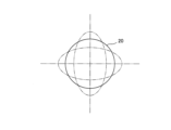
- the annular oscillator 20 periodically undergoes primary vibrations so as to form an ellipse with mutually perpendicular principal axes. Meanwhile, when an angular velocity is applied to the oscillator 20, a Coriolis force is generated, and a new vibration is excited by the Coriolis force in the direction of 45 degrees from the principal axis of the primary vibration shown in Figure 5. This vibration is called secondary vibration, and its vibration state is shown in Figure 6.
- a magnetic field is also applied to the secondary detection electrode SPO in a direction intersecting its surface. Furthermore, in response to the vibration of the vibrator 20, the secondary detection electrode SPO also vibrates in a direction parallel to its surface. As a result, a sinusoidal AC voltage is generated in the secondary detection electrode SPO according to the strength of the magnetic field and the movement speed during vibration. The voltage detected in the secondary detection electrode SPO is proportional to the magnitude of the secondary vibration excited by the Coriolis force, so the voltage generated also differs depending on the magnitude of the applied angular velocity.
- the secondary detection unit 140 detects the voltage generated at the secondary detection electrode SPO and outputs an output signal corresponding to the magnitude of this voltage to the secondary AC power supply 130.
- the output signal of the secondary detection unit 140 is input to the secondary AC power supply 130. Based on this output signal, the secondary AC power supply 130 supplies an AC current to the secondary drive electrode SD so as to cancel out the secondary vibration generated in the vibrator 20, thereby suppressing the secondary vibration. In other words, feedback control is performed so that the output of the secondary detection electrode SPO becomes zero.
- the secondary AC power supply 130 also inputs an output signal based on the output current to the calculation unit 150.
- the calculation unit 150 can calculate the angular velocity based on the output signal of the secondary AC power supply 130.
- the vibration type gyro element 100 is configured to be able to swap the primary drive electrode PD and its wiring 70 with the secondary drive electrode SD and its wiring 70, and to swap the primary detection electrode PPO and its wiring 70 with the secondary detection electrode SPO and its wiring 70.
- the gyroscope 101 performs the swap at a predetermined timing, acquires output signals from the vibration type gyro element 100 before and after the swap, and calculates the angular velocity based on these output signals using the calculation unit 150.
- the calculation unit 150 calculates the angular velocity based on the difference between the output signals before and after the swap. This swap is performed by switching the internal wiring using the switch 170 and the switching control unit 160 shown in FIG. 4.
- One switch 170 is provided for each of the primary drive electrode PD, the secondary drive electrode SD, the primary detection electrode PPO, and the secondary detection electrode SPO.
- the "predetermined timing" is selected when the vibration type gyro element 100 is stationary or in a constant speed motion state, or when there is another gyro that can measure and interpolate the motion during switching.
- the switch 170 is an example of a "switching unit" in the claims.
- Electrodes 40b, 40d, 40f, and 40h are electrically connected to the primary AC power supply 110 and function as primary drive electrodes PD. Electrodes 40j, 40l, 40n, and 40p are electrically connected to the primary detection unit 120 and function as primary detection electrodes PPO. Electrodes 40a, 40c, 40e, and 40g are electrically connected to the secondary AC power supply 130 and function as secondary drive electrodes SD. Electrodes 40i, 40k, 40m, and 40o are electrically connected to the secondary detection unit 140 and function as secondary detection electrodes SPO.
- wiring 70a which will be described later, is electrically connected to the primary AC power supply 110.
- Wiring 70c which will be described later, is electrically connected to the primary detection unit 120.
- Wiring 70b which will be described later, is electrically connected to the secondary AC power supply 130.
- wiring 70d is electrically connected to the secondary detection unit 140.
- the switching control unit 160 sends a control signal to the four switches 170, thereby switching the internal wiring of the gyroscope 101.
- the electrode arrangement is switched to the electrode arrangement after the exchange shown in FIG. 8.
- the electrodes 40b, 40d, 40f, and 40h are electrically connected to the secondary AC power supply 130 and function as secondary drive electrodes SD.
- the electrodes 40j, 40l, 40n, and 40p are electrically connected to the secondary detection unit 140 and function as secondary detection electrodes SPO.
- the electrodes 40a, 40c, 40e, and 40g are connected to the primary AC power supply 110 and function as primary drive electrodes PD.
- the electrodes 40i, 40k, 40m, and 40o are connected to the primary detection unit 120 and function as primary detection electrodes PPO.
- the wiring 70a which will be described later, is electrically connected to the secondary AC power supply 130.
- the wiring 70c which will be described later, is electrically connected to the secondary detection unit 140.
- wiring 70b which will be described later, is electrically connected to the primary AC power source 110.
- wiring 70d which will be described later, is electrically connected to the primary detection unit 120.
- the vibration type gyro element 100, the primary AC power supply 110, the primary detection unit 120, the secondary AC power supply 130, the secondary detection unit 140, and the calculation unit 150 may be mounted on separate substrates, or may be mounted on the same substrate.
- the vibration type gyro element 100, the primary AC power supply 110, the primary detection unit 120, the secondary AC power supply 130, the secondary detection unit 140, and the calculation unit 150 may be housed in separate packages (not shown).
- the vibration type gyro element 100 and other components may be mounted on separate substrates or housed in separate packages. In that case, the primary AC power supply 110 and the secondary AC power supply 130 may be mounted on yet another substrate or housed in another package.
- the multiple wirings 70 include wirings 70a, 70b, 70c, and 70d. Each of the wirings 70a to 70d is provided with a bonding wire 80.
- the wirings 70a and 70b are wirings to be replaced.
- the wirings 70c and 70d are wirings to be replaced.
- the wirings 70a, 70b, 70c, and 70d are hatched differently from one another.
- the wiring 70a is provided corresponding to the electrodes 40b, 40d, 40f, and 40h, and connects the electrodes 40b, 40d, 40f, and 40h in series with each other.
- the wiring 70a has a portion that connects the electrode 40b to the circuit on the substrate on which the vibration type gyro element 100 is mounted (and thus the primary AC power source 110 or the secondary AC power source 130), a portion that connects the electrode 40b to the electrode 40d, a portion that connects the electrode 40d to the electrode 40f via the substrate circuit, a portion that connects the electrode 40f to the electrode 40h, and a portion that connects the electrode 40h to the substrate circuit (and thus the primary AC power source 110 or the secondary AC power source 130).
- the wiring 70a is provided with two bonding wires 80a and 80b.
- the bonding wire 80a is provided in the portion between the electrodes 40b and 40d of the wiring 70a.
- bonding wire 80b is provided in the portion of wiring 70a between electrodes 40f and 40h.
- the wiring 70b is provided corresponding to the electrodes 40a, 40c, 40e, and 40g, and connects the electrodes 40a, 40c, 40e, and 40g in series with each other.
- the wiring 70b has a portion that connects the circuit on the board side (and thus the primary AC power supply 110 or the secondary AC power supply 130) and the electrode 40e, a portion that connects the electrodes 40e and 40c, a portion that connects the electrodes 40c and 40a via the circuit on the board side, a portion that connects the electrodes 40a and 40g, and a portion that connects the electrode 40g and the circuit on the board side (and thus the primary AC power supply 110 or the secondary AC power supply 130).
- the wiring 70b is provided with two bonding wires 80c and 80d.
- the bonding wire 80c is provided in the portion between the electrodes 40e and 40c of the wiring 70b.
- bonding wire 80d is provided in the portion of wiring 70b between electrodes 40a and 40g.
- the wiring 70c is provided corresponding to the electrodes 40j, 40l, 40n, and 40p, and connects the electrodes 40j, 40l, 40n, and 40p in series with each other.
- the wiring 70c has a portion that connects the circuit on the board side (and thus the primary detection unit 120 or the secondary detection unit 140) and the electrode 40l, a portion that connects the electrode 40l and the electrode 40n, a portion that connects the electrode 40n and the electrode 40p via the circuit on the board side, a portion that connects the electrode 40p and the electrode 40j, and a portion that connects the electrode 40j and the circuit on the board side (and thus the primary detection unit 120 or the secondary detection unit 140).
- the wiring 70c is provided with two bonding wires 80e and 80f.
- the bonding wire 80e is provided in the portion of the wiring 70c between the electrode 40l and the electrode 40n.
- bonding wire 80f is provided in the portion of wiring 70c between electrode 40p and electrode 40j.
- the wiring 70d is provided corresponding to the electrodes 40i, 40k, 40m, and 40o, and connects the electrodes 40i, 40k, 40m, and 40o in series with each other.
- the wiring 70d has a portion that connects the circuit on the board side (and thus the primary detection unit 120 or the secondary detection unit 140) and the electrode 40k, a portion that connects the electrode 40k and the electrode 40i, a portion that connects the electrode 40i and the electrode 40o via the circuit on the board side, a portion that connects the electrode 40o and the electrode 40m, and a portion that connects the electrode 40m and the circuit on the board side (and thus the primary detection unit 120 or the secondary detection unit 140).
- the wiring 70d is provided with two bonding wires 80g and 80h.
- the bonding wire 80g is provided in the portion of the wiring 70d between the electrode 40k and the electrode 40i.
- bonding wire 80h is provided in the portion of wiring 70d between electrode 40o and electrode 40m.
- the vibrating gyro element 100 adjusts the pattern of the wiring 70 in the fixed portion 10 and the number of bonding wires 80 provided on the wiring 70 to match the resistance components between the switch 170 and the vibrator 20 between the electrodes 40 and their wiring 70 to be swapped.
- the resistance components of the electrodes 40 and wiring 70 refer to the electrical resistance values of the electrodes 40 and wiring 70.
- the resistance components of the electrodes 40 and wiring 70 are smaller as the cross-sectional areas of the electrodes 40 and wiring 70 are larger, and are larger as the lengths of the electrodes 40 and wiring 70 are larger.
- the resistance components of the electrodes 40 and their wiring 70 to be replaced in the range connected in series are matched between the switch 170 and the vibrator 20.
- the resistance components of the electrodes 40 and their wiring 70 to be replaced provided on the vibrator 10, the fixed part 20, and the support part 30 are matched between the switches 170 and the vibrator 20.
- the number of bonding wires 80 is made the same for the wirings 70a, 70b and 70c, 70d to be replaced, so that the resistance components between the switch 170 and the vibrator 20 are matched for the electrodes 40 to be replaced and their wirings 70.
- two bonding wires 80 (80a to 80d) are provided for each of the wirings 70a, 70b to be replaced.
- two bonding wires 80 (80e to 80h) are provided for each of the wirings 70c, 70d to be replaced.
- the lengths of the bonding wires 80 for the wirings 70a, 70b and 70c, 70d to be swapped are made the same, so that the resistance components between the switch 170 and the vibrator 20 are matched for the electrode 40 to be swapped and the wirings 70 thereof. That is, each of the bonding wires 80a to 80d corresponding to the wirings 70a and 70b has the same length L. Also, each of the bonding wires 80e to 80h corresponding to the wirings 70c and 70d has the same length L. All of the multiple bonding wires 80 have the same length L. Also, all of the multiple bonding wires 80 have the same width (diameter). Note that, for convenience, in Figure 10, only the bonding wires 80a, 80d, and 80g are illustrated with the length L.
- one bonding wire 80 and the other bonding wires 80 are not parallel to each other or are spaced apart.
- bonding wire 80a and each of the other bonding wires 80b to 80h are not parallel to each other or are spaced apart.
- bonding wire 80a and bonding wire 80g closest to bonding wire 80a are not parallel to each other but are spaced apart. Note that while the above description has been given for bonding wire 80a, the same applies to bonding wires 80b to 80h.
- the cross-sectional areas of the wirings 70a, 70b and 70c, 70d to be replaced are matched to each other, thereby matching the resistance components between the switch 170 and the vibrator 20 between the electrode 40 to be replaced and the wirings 70 to be replaced.
- the cross-sectional areas of the wirings 70a, 70b and 70c, 70d to be replaced are matched to each other by matching the widths of the wirings 70a, 70b and 70c, 70d to be replaced.
- Each of the wirings 70a, 70b, 70c, and 70d has a wide portion and a narrow portion, and the wide portion has a width W1 (see FIG. 10), and the narrow portion has a width W2 (see FIG. 10) that is smaller than the width W1. That is, the widths of the wirings 70a, 70b, 70c, and 70d to be replaced are matched.
- the processing errors due to the manufacturing process when forming the wirings 70a, 70b, 70c, and 70d in the fixed portion 10 can be matched, so that the variation in the resistance components caused by the processing errors can be reduced, and the resistance components of the wirings 70a, 70b, 70c, and 70d to be replaced can be more easily matched.
- the widths W1 and W2 are illustrated only for the wirings 70c and 70d.
- the resistance components between the switch 170 and the vibrator 20 are matched between the wirings 70a, 70b, 70c, 70d to be replaced.
- the values obtained by dividing the length by the cross-sectional area of the wirings 70a, 70b, 70c, 70d to be replaced are matched between the wirings 70a, 70b, 70c, 70d to be replaced.
- each of the wirings 70a, 70b, 70c, 70d has the same thickness.
- the thickness of each of the wirings 70a, 70b, 70c, and 70d is sufficiently smaller than the width of the bonding wire 80 (e.g., 30 ⁇ m). That is, the wirings 70a, 70b, 70c, and 70d have a smaller cross-sectional area than the bonding wire 80.
- the electrodes 40 to be replaced are matched in resistance between the switch 170 and the vibrator 20.
- the electrodes 40 to be replaced refer to electrodes 40b, 40d, 40f, 40h, electrodes 40a, 40c, 40e, 40g, electrodes 40j, 40l, 40n, 40p, and electrodes 40i, 40k, 40m, 40o.
- the electrodes 40a to 40h each have the same shape. That is, the electrodes 40a to 40h each have the same thickness, width, and length. Therefore, the cross-sectional area and length of the electrodes 40b, 40d, 40f, and 40h match with those of the electrodes 40a, 40c, 40e, and 40g.
- the electrodes 40i to 40p each have the same shape. That is, the electrodes 40i to 40p each have the same thickness, width, and length. Therefore, the cross-sectional area and length of the electrodes 40j, 40l, 40n, and 40p match with those of the electrodes 40i, 40k, 40m, and 40o.
- the resistance components of the electrodes 40 and their wiring 70 that are to be swapped are matched between the switch 170 and the vibrator 20.
- the vibrating gyro element 100 includes a vibrator 20, a plurality of electrodes 40 arranged on the vibrator 20, and a plurality of wirings 70 provided corresponding to the plurality of electrodes 40.
- the plurality of electrodes 40 include a primary drive electrode PD that excites the vibrator 20 to a primary vibration, a primary detection electrode PPO that detects the primary vibration, a secondary detection electrode SPO that detects the secondary vibration of the vibrator 20, and a secondary drive electrode SD that drives the vibrator 20 to cancel the secondary vibration.
- a switch 170 is provided to switch between the primary drive electrode PD and its wiring 70 and the secondary drive electrode SD and its wiring 70, and to switch between the primary detection electrode PPO and its wiring 70 and the secondary detection electrode SPO and its wiring 70.
- the above configuration allows the resistance components of the electrodes 40 and their wiring 70 performing each function to be matched before and after the swap, reducing the difference in bias components due to electrical crosstalk corresponding to the resistance components that are superimposed on the output signals before and after the swap.
- the bias components due to electrical crosstalk corresponding to the resistance components can be sufficiently canceled.
- the detection accuracy of angular velocity can be improved in the gyroscope 101 equipped with the vibration type gyro element 100.
- the resistance components between the switch 170 and the vibrator 20 are matched for the electrodes 40 to be replaced and their wirings 70.
- the bonding wires 80 have a different thickness from the wirings 70, and therefore the resistance values are also different. Also, even if the total distance of the wirings 70 is the same, the resistance value may differ depending only on the presence or absence of the bonding wires 80.
- the number of bonding wires 80 the same for the wirings 70 to be replaced as described above, the effect of providing the bonding wires 80 itself due to the thickness can be suppressed, and therefore the resistance components between the electrodes 40 to be replaced and their wirings 70 can be easily matched.
- the lengths of the bonding wires 80 in the wirings 70 to be swapped are made the same, so that the resistance components of the electrodes 40 to be swapped and their wirings 70 are matched between the switch 170 and the vibrator 20. This makes it easier to match the resistance components of the electrodes 40 to be swapped and their wirings 70.
- the first bonding wire 80 and the other bonding wires 80 are not parallel to each other or are spaced apart from each other. This makes it possible to prevent mutual induction from occurring between the first bonding wire 80 and the other bonding wires 80, unlike when the first bonding wire 80 and the other bonding wires 80 are parallel and arranged nearby, and therefore makes it possible to prevent mutual induction between the first bonding wire 80 and the other bonding wires 80 from adversely affecting the output signal.
- the electrodes 40 to be replaced are provided in equal numbers (two or more) and are connected in series by wiring 70, and the resistance components of the electrodes 40 to be replaced and their wiring 70 in the range connected in series are matched between the switch 170 and the vibrator 20.
- the need to route the wiring 70 connecting the multiple electrodes 40 makes the lengths of the wiring 70 different and complicated, requiring three-dimensional wiring 70 with bonding wires to bypass each other, and the design is likely to have different resistance components, so there is a great effect in matching the resistance components of the electrodes 40 to be replaced and their wiring 70.
- the cross-sectional areas of the wirings 70 to be replaced are matched, thereby matching the resistance components of the electrode 40 to be replaced and its wirings 70. This makes effective use of the fact that the resistance components change depending on the cross-sectional area of the wiring 70, making it possible to easily match the resistance components of the electrode 40 to be replaced and its wirings 70.
- the widths of the wirings 70 to be replaced are matched, thereby matching the cross-sectional areas of the wirings 70 to be replaced. This makes effective use of the fact that the cross-sectional area changes depending on the width of the wiring 70, making it possible to easily match the cross-sectional areas of the wirings 70 to be replaced.
- the vibrating gyro element 100 includes a fixed portion 10 and a support portion 30 that connects the vibrator 20 to the fixed portion 10 and supports the vibrator 20 so that it can vibrate, the wiring 70 is provided on the fixed portion 10, the electrodes 40 are provided on the vibrator 10 and the support portion 30, and the electrodes 40 and their wiring 70 that are to be replaced and that are provided on the vibrator 10, the fixed portion 20, and the support portion 30 match each other's resistance components between the switch 170 and the vibrator 20. This makes it possible to easily vibrate the vibrator 20, and also to match each other's resistance components between the electrodes 40 and their wiring 70 that are to be replaced.
- Table 1 below shows the measurement results of the resistance components of PD, SD, PPO, and SPO before replacement in the vibration type gyro element 100 of the embodiment in which the number of bonding wires 80 is the same between the wirings 70 to be replaced.
- PD represents the resistance component between the electrodes 40b, 40d, 40f, and 40h and the wiring 70a.
- SD represents the resistance component between the electrodes 40a, 40c, 40e, and 40g and the wiring 70b.
- PPO represents the resistance component between the electrodes 40j, 40l, 40n, and 40p and the wiring 70c.
- SPO represents the resistance component between the electrodes 40i, 40k, 40m, and 40o and the wiring 70d.
- the function of PD is carried out by the electrodes 40a, 40c, 40e, and 40g and the wiring 70b.
- the electrodes 40b, 40d, 40f, and 40h and the wiring 70a function as SD
- the electrodes 40i, 40k, 40m, and 40o and the wiring 70d function as PPO
- the electrodes 40j, 40l, 40n, and 40p and the wiring 70c function as SPO.
- the resistance components of the PD and SD were almost equal, and the resistance components of the PPO and SPO were almost equal.
- the number of bonding wires 80 the same for the wirings 70 to be replaced, it was possible to match the resistance components of the electrodes 40 and their wirings 70 to be replaced.
- By matching the resistance components of the electrodes 40 and their wirings 70 to be replaced it was possible to match the resistance components of the electrodes 40 and their wirings 70 before and after replacement of an electrode 40 and its wiring 70 that has a certain function (for example, the PD before replacement and the PD after replacement).
- the resistance components between the switch and the vibrator for the electrodes to be swapped and their wiring were adjusted by adjusting the wiring pattern and the number of bonding wires provided on the wiring, but the present invention is not limited to this.
- the resistance components between the switching unit and the vibrator for the electrodes to be swapped and their wiring may be adjusted by adjusting only the wiring pattern.
- other electrical elements that increase or decrease the electrical resistance may be provided on the wiring to adjust the resistance components between the switching unit and the vibrator for the electrodes to be swapped and their wiring.
- the present invention is not limited to this.
- the number of bonding wires in the wirings to be replaced may be 0, 1, or 3 or more. In other words, the number of bonding wires may be 0 in both cases.
- the bonding wires of the wirings to be swapped have the same length, but the present invention is not limited to this.
- the bonding wires of the wirings to be swapped may have different lengths.
- all bonding wires are the same length, but the present invention is not limited to this.
- all bonding wires do not have to be the same length.
- the lengths of the bonding wires of the wirings to be replaced may be the same, while the lengths of the bonding wires of one wiring to be replaced and the other wiring to be replaced may be different.
- the other wiring to be replaced may have two bonding wires, so that the lengths of the bonding wires of all the wirings to be replaced are the same.
- one bonding wire and another bonding wire are spaced apart so as not to be arranged parallel to each other, but the present invention is not limited to this.
- one bonding wire and another bonding wire that are sufficiently spaced apart from each other may be arranged parallel to each other.
- multiple primary drive electrodes, multiple primary detection electrodes, multiple secondary drive electrodes, and multiple secondary detection electrodes are divided into several sections (for example, two sections) and each divided section is separately connected to an independent circuit on the substrate side, it is preferable that the resistance components of each section match the other sections to be replaced.
- the primary drive electrodes, primary detection electrodes, secondary drive electrodes, and secondary detection electrodes were each arranged in four orientations, but the present invention is not limited to this.
- the primary drive electrodes, primary detection electrodes, secondary drive electrodes, and secondary detection electrodes may each be arranged in two orientations.
- the primary vibration of the cos2 ⁇ mode was excited in the vibrator, but the present invention is not limited to this.
- the primary vibration of the cosN ⁇ mode (N is a natural number equal to or greater than 2) may be excited in the vibrator.
- the support parts and electrodes are provided in 4N orientations arranged at equal angular intervals around the circumference of the vibrator.
- the vibrator is annular, but the present invention is not limited to this.
- the vibrator may be ring-shaped, such as a regular polygon.
- the vibrator may also be disk-shaped, hemispherical, or the like.
- the shape of the support part shown in the above embodiment is merely an example and is not limited to this. If there is no or only a small effect on the increase or decrease in the resistance component of the electrode and its wiring to be swapped, other electrical elements may be provided between the switching part and the vibrator for the purpose of performing a function unrelated to the present invention. In this case, different electrical elements may be provided between the electrodes and their wiring to be swapped. Furthermore, if the effects before and after the swap can be offset by providing electrical elements of similar configurations between the electrodes and their wiring to be swapped, other electrical elements may be provided between the switching part and the vibrator even if the effect on the resistance component is large.
- the primary drive electrode is replaced with the secondary drive electrode and the primary detection electrode is replaced with the secondary detection electrode, but the present invention is not limited to this.
- the primary drive electrode may be replaced with the secondary detection electrode and the primary detection electrode may be replaced with the secondary drive electrode.
- the support part and the vibrator are provided with two electrodes in parallel to each other, but the present invention is not limited to this.
- the support part and the vibrator may be provided with three or more electrodes in parallel to each other. That is, the number of rows of electrodes may be three or more.
- the support part may include dummy electrodes with no electrodes arranged thereon. Depending on the shape of the vibrator, there may be only one support part. Also, the support part itself may not exist. In this case, too, the same effect as in the above embodiment can be obtained by adjusting the resistance components to be replaced by measures such as the wiring pattern after the switching part, the number of bonding wires provided on the wiring, or the installation of other electrical elements.
- the shape of the fixed part shown in the above embodiment is merely an example and is not limited to this.
- the shape of the fixed part is not limited to a square, and the center of the fixed part and the center of the vibrator do not need to coincide.
- the angle of the support part relative to the center of the vibrator, the angle of the fixed part, and the angle of the electrodes on the vibrator are not limited.
- wiring and electrodes are provided on the surfaces of the fixing part and the support part to electrically connect to each electrode on the vibrator surface, but wiring to members other than the fixing part and the support part may also electrically connect to each electrode on the vibrator.
- effects similar to those of the above embodiment can be obtained by adjusting the resistance components to be replaced by measures such as the wiring pattern between the switching part and the vibrator, the number of bonding wires provided on the wiring, or the installation of other electrical elements.
- switches as switching units for switching each electrode and its wiring may be provided on the entrance side and the exit side.
- the resistance components of the electrodes and their wiring to be switched between the entrance side switch and the exit side switch are matched to each other. This makes it possible to match the resistance components between the entrance side switch and the exit side switch, so that the bias components due to electrical crosstalk corresponding to the resistance components can be sufficiently canceled.
- REFERENCE SIGNS LIST 10 Fixed portion 20 Vibrator 30 Support portion 40, 40a to 40p Electrodes 70, 70a to 70d Wiring 80, 80a to 80h Bonding wires 100 Vibration type gyro element 101 Gyroscope 150 Calculation portion PD Primary drive electrode SD Secondary drive electrode PPO Primary detection electrode SPO Secondary detection electrode
Landscapes
- Engineering & Computer Science (AREA)
- Physics & Mathematics (AREA)
- General Physics & Mathematics (AREA)
- Radar, Positioning & Navigation (AREA)
- Remote Sensing (AREA)
- Signal Processing (AREA)
- Manufacturing & Machinery (AREA)
- Gyroscopes (AREA)
Priority Applications (2)
| Application Number | Priority Date | Filing Date | Title |
|---|---|---|---|
| EP24778954.8A EP4692727A1 (en) | 2023-03-29 | 2024-02-27 | Vibration gyro element and gyroscope |
| JP2025510002A JPWO2024202813A1 (https=) | 2023-03-29 | 2024-02-27 |
Applications Claiming Priority (2)
| Application Number | Priority Date | Filing Date | Title |
|---|---|---|---|
| JP2023-054342 | 2023-03-29 | ||
| JP2023054342 | 2023-03-29 |
Publications (1)
| Publication Number | Publication Date |
|---|---|
| WO2024202813A1 true WO2024202813A1 (ja) | 2024-10-03 |
Family
ID=92905214
Family Applications (1)
| Application Number | Title | Priority Date | Filing Date |
|---|---|---|---|
| PCT/JP2024/006970 Ceased WO2024202813A1 (ja) | 2023-03-29 | 2024-02-27 | 振動型ジャイロ素子およびジャイロスコープ |
Country Status (3)
| Country | Link |
|---|---|
| EP (1) | EP4692727A1 (https=) |
| JP (1) | JPWO2024202813A1 (https=) |
| WO (1) | WO2024202813A1 (https=) |
Citations (3)
| Publication number | Priority date | Publication date | Assignee | Title |
|---|---|---|---|---|
| JPH115559A (ja) | 1997-06-18 | 1999-01-12 | Nissan Motor Co Ltd | 自動車のサブフレーム |
| JP2009115559A (ja) | 2007-11-05 | 2009-05-28 | Sumitomo Precision Prod Co Ltd | 角速度センサ及び角速度センサを備えた電子機器 |
| JP2013225590A (ja) * | 2012-04-20 | 2013-10-31 | Mitsubishi Electric Corp | 半導体装置 |
-
2024
- 2024-02-27 JP JP2025510002A patent/JPWO2024202813A1/ja active Pending
- 2024-02-27 EP EP24778954.8A patent/EP4692727A1/en active Pending
- 2024-02-27 WO PCT/JP2024/006970 patent/WO2024202813A1/ja not_active Ceased
Patent Citations (3)
| Publication number | Priority date | Publication date | Assignee | Title |
|---|---|---|---|---|
| JPH115559A (ja) | 1997-06-18 | 1999-01-12 | Nissan Motor Co Ltd | 自動車のサブフレーム |
| JP2009115559A (ja) | 2007-11-05 | 2009-05-28 | Sumitomo Precision Prod Co Ltd | 角速度センサ及び角速度センサを備えた電子機器 |
| JP2013225590A (ja) * | 2012-04-20 | 2013-10-31 | Mitsubishi Electric Corp | 半導体装置 |
Non-Patent Citations (1)
| Title |
|---|
| See also references of EP4692727A1 |
Also Published As
| Publication number | Publication date |
|---|---|
| EP4692727A1 (en) | 2026-02-11 |
| JPWO2024202813A1 (https=) | 2024-10-03 |
Similar Documents
| Publication | Publication Date | Title |
|---|---|---|
| JP7713585B2 (ja) | 振動型ジャイロ素子およびジャイロスコープ | |
| JP6514790B2 (ja) | ジャイロスコープ | |
| JP7808119B2 (ja) | 振動型ジャイロスコープ及びこれを備えた角速度センサ | |
| JP5773844B2 (ja) | 出力安定性に優れた振動型ジャイロ | |
| JP2009002834A (ja) | 角速度検出装置 | |
| EP4163250B1 (en) | Vibratory gyro element and angular velocity sensor comprising same | |
| JP7269745B2 (ja) | 振動構造の角速度センサ、およびその製造方法 | |
| WO2024202813A1 (ja) | 振動型ジャイロ素子およびジャイロスコープ | |
| WO2024202814A1 (ja) | 振動型ジャイロ素子およびジャイロスコープ | |
| JP7402341B2 (ja) | 振動型ジャイロ素子及びこれを備えた角速度センサ | |
| JP2013108929A (ja) | 高精度化された振動型ジャイロ | |
| WO2026069997A1 (ja) | ジャイロスコープ | |
| JP5816707B2 (ja) | 角速度検出装置 | |
| JP5481545B2 (ja) | 角速度検出装置 | |
| WO2025205848A1 (ja) | ジャイロスコープ | |
| JP2016008907A (ja) | 温度特性に優れた振動型ジャイロ | |
| JP2017150997A (ja) | バイアスの低減が図られた振動型ジャイロ | |
| JPH06249666A (ja) | 振動ジャイロ |
Legal Events
| Date | Code | Title | Description |
|---|---|---|---|
| 121 | Ep: the epo has been informed by wipo that ep was designated in this application |
Ref document number: 24778954 Country of ref document: EP Kind code of ref document: A1 |
|
| ENP | Entry into the national phase |
Ref document number: 2025510002 Country of ref document: JP Kind code of ref document: A |
|
| WWE | Wipo information: entry into national phase |
Ref document number: 2025510002 Country of ref document: JP |
|
| WWE | Wipo information: entry into national phase |
Ref document number: 2024778954 Country of ref document: EP |
|
| NENP | Non-entry into the national phase |
Ref country code: DE |
|
| ENP | Entry into the national phase |
Ref document number: 2024778954 Country of ref document: EP Effective date: 20251029 |
|
| ENP | Entry into the national phase |
Ref document number: 2024778954 Country of ref document: EP Effective date: 20251029 |
|
| ENP | Entry into the national phase |
Ref document number: 2024778954 Country of ref document: EP Effective date: 20251029 |
|
| ENP | Entry into the national phase |
Ref document number: 2024778954 Country of ref document: EP Effective date: 20251029 |
|
| ENP | Entry into the national phase |
Ref document number: 2024778954 Country of ref document: EP Effective date: 20251029 |
|
| ENP | Entry into the national phase |
Ref document number: 2024778954 Country of ref document: EP Effective date: 20251029 |
|
| ENP | Entry into the national phase |
Ref document number: 2024778954 Country of ref document: EP Effective date: 20251029 |
|
| ENP | Entry into the national phase |
Ref document number: 2024778954 Country of ref document: EP Effective date: 20251029 |
|
| WWP | Wipo information: published in national office |
Ref document number: 2024778954 Country of ref document: EP |