WO2024202736A1 - 窒化ケイ素粉末およびそれを用いた樹脂組成物 - Google Patents
窒化ケイ素粉末およびそれを用いた樹脂組成物 Download PDFInfo
- Publication number
- WO2024202736A1 WO2024202736A1 PCT/JP2024/006305 JP2024006305W WO2024202736A1 WO 2024202736 A1 WO2024202736 A1 WO 2024202736A1 JP 2024006305 W JP2024006305 W JP 2024006305W WO 2024202736 A1 WO2024202736 A1 WO 2024202736A1
- Authority
- WO
- WIPO (PCT)
- Prior art keywords
- silicon nitride
- nitride powder
- powder
- less
- particles
- Prior art date
- Legal status (The legal status is an assumption and is not a legal conclusion. Google has not performed a legal analysis and makes no representation as to the accuracy of the status listed.)
- Ceased
Links
Classifications
-
- C—CHEMISTRY; METALLURGY
- C01—INORGANIC CHEMISTRY
- C01B—NON-METALLIC ELEMENTS; COMPOUNDS THEREOF; METALLOIDS OR COMPOUNDS THEREOF NOT COVERED BY SUBCLASS C01C
- C01B21/00—Nitrogen; Compounds thereof
- C01B21/06—Binary compounds of nitrogen with metals, with silicon, or with boron, or with carbon, i.e. nitrides; Compounds of nitrogen with more than one metal, silicon or boron
- C01B21/068—Binary compounds of nitrogen with metals, with silicon, or with boron, or with carbon, i.e. nitrides; Compounds of nitrogen with more than one metal, silicon or boron with silicon
-
- C—CHEMISTRY; METALLURGY
- C08—ORGANIC MACROMOLECULAR COMPOUNDS; THEIR PREPARATION OR CHEMICAL WORKING-UP; COMPOSITIONS BASED THEREON
- C08K—Use of inorganic or non-macromolecular organic substances as compounding ingredients
- C08K3/00—Use of inorganic substances as compounding ingredients
- C08K3/34—Silicon-containing compounds
-
- C—CHEMISTRY; METALLURGY
- C08—ORGANIC MACROMOLECULAR COMPOUNDS; THEIR PREPARATION OR CHEMICAL WORKING-UP; COMPOSITIONS BASED THEREON
- C08L—COMPOSITIONS OF MACROMOLECULAR COMPOUNDS
- C08L63/00—Compositions of epoxy resins; Compositions of derivatives of epoxy resins
-
- C—CHEMISTRY; METALLURGY
- C01—INORGANIC CHEMISTRY
- C01P—INDEXING SCHEME RELATING TO STRUCTURAL AND PHYSICAL ASPECTS OF SOLID INORGANIC COMPOUNDS
- C01P2004/00—Particle morphology
- C01P2004/60—Particles characterised by their size
- C01P2004/61—Micrometer sized, i.e. from 1-100 micrometer
-
- C—CHEMISTRY; METALLURGY
- C01—INORGANIC CHEMISTRY
- C01P—INDEXING SCHEME RELATING TO STRUCTURAL AND PHYSICAL ASPECTS OF SOLID INORGANIC COMPOUNDS
- C01P2006/00—Physical properties of inorganic compounds
- C01P2006/11—Powder tap density
-
- C—CHEMISTRY; METALLURGY
- C01—INORGANIC CHEMISTRY
- C01P—INDEXING SCHEME RELATING TO STRUCTURAL AND PHYSICAL ASPECTS OF SOLID INORGANIC COMPOUNDS
- C01P2006/00—Physical properties of inorganic compounds
- C01P2006/12—Surface area
Definitions
- This disclosure relates to silicon nitride powder and a resin composition using the same.
- Heat generated by passing current through an electronic component is dissipated via a heat sink.
- a technique is known in which a heat dissipation material is filled between the electronic component and the heat sink.
- One type of heat dissipation material is a resin composition containing a resin and inorganic particles, and it is known that silicon nitride powder can be used as the inorganic particles (for example, Patent Document 1).
- Patent document 1 discloses a low-aluminum spherical ⁇ silicon nitride powder used as a filler in electronic packaging materials.
- the silicon nitride powder is characterized by a sphericity of 0.5 to 0.99, an Al impurity content of less than 500 ppm, and a particle size range of 0.5 ⁇ m to 50 ⁇ m.
- Patent Document 2 discloses a method for producing silicon nitride powder suitable for producing silicon nitride sintered bodies and silicon nitride powder obtained by said method.
- the silicon nitride powder has an average particle size of 1-50 ⁇ m, a metal oxide content of 0-10 wt%, and an impurity content of less than 1 wt%, preferably a metal oxide content of less than 1 wt%, and the sintered body has a thermal conductivity of 90 W/mK or more and a bending strength of 700 MPa or more, and preferably the sintering conditions for the sintered body are to mix the silicon nitride powder with MgO and Y 2 O 3 , polish, dry press mold the base, and gas pressure sinter the base at 1900° C. and 1 MPa nitrogen gas pressure for 8 hours.
- Patent Document 3 discloses silicon nitride powder suitable for producing highly thermally conductive silicon nitride sintered bodies.
- the silicon nitride powder is characterized by having a ⁇ fraction of 30-100%, an oxygen content of less than 0.5 wt%, an average particle size of 0.2-10 ⁇ m, an aspect ratio of 10 or less, and containing columnar particles with grooves formed in the long axis direction of the particle.
- the performance of semiconductor components contained in electronic components may be degraded by moisture. If the resin composition used as a heat dissipation material contains a large amount of moisture, the moisture may seep out of the resin composition and reach the electronic components. In order to reduce the moisture content of the resin composition as much as possible, it is desirable to use silicon nitride powder, which has a low moisture content, as a filler.
- Patent Document 1 does not consider the moisture content of the silicon nitride particles used as a filler.
- the silicon nitride powders in Patent Documents 2 and 3 disclose silicon nitride powders for use in silicon nitride sintered bodies, and therefore do not discuss mixing with a resin to form a resin composition, nor do they discuss silicon nitride powders suitable as fillers for resin compositions. Furthermore, Patent Documents 2 and 3 do not discuss the moisture content of silicon nitride particles.
- one embodiment of the present invention aims to provide a silicon nitride powder that is used as a filler for resin compositions and has a low moisture content. Furthermore, another embodiment of the present invention aims to provide a resin composition that uses the silicon nitride powder according to one embodiment.
- the silicon nitride powder includes a plurality of silicon nitride particles and has an Rsp value to ethanol of less than 105.6.
- Aspect 2 of the present invention is 2.
- Aspect 3 of the present invention is The silicon nitride powder according to aspect 1 or 2, wherein the silicon nitride particles have a specific surface area equivalent diameter of more than 0.71 ⁇ m.
- Aspect 4 of the present invention is A silicon nitride powder according to any one of Aspects 1 to 3, having a specific surface area of less than 2.66 m 2 /g.
- Aspect 5 of the present invention is The silicon nitride powder according to any one of aspects 1 to 4, having an apparent density of greater than 3.17 g/ cm3 .
- Aspect 6 of the present invention is The silicon nitride powder according to any one of aspects 1 to 5, wherein the ratio (L2/L1) of the total length L2 of the internal boundary lines to the length L1 of the outer edge is 1% or less, and the maximum particle size of the silicon nitride particles is 6.8 ⁇ m or more.
- Aspect 7 of the present invention is A resin composition comprising a resin and the silicon nitride powder according to any one of Aspects 1 to 6.
- a resin composition with a low moisture content can be obtained.
- the Rsp value for water is used as an indicator for controlling the moisture content of silicon nitride powder.
- the inventors considered using a dispersion medium other than water because it is difficult to prepare a sample to measure the Rsp value for water and it may be difficult to obtain an accurate value.
- the Rsp value for ethanol is relatively easy to prepare a sample for measurement, makes it easy to obtain an accurate value, and is also appropriate as an indicator for controlling the moisture content of silicon nitride powder.
- the Rsp value for ethanol is an index relating to the mobility of the molecules of the dispersion medium (ethanol molecules) adsorbed on the surface of the silicon nitride powder.
- the silicon nitride powder dispersed in the silicon nitride slurry is dispersed in the silicon nitride slurry with the molecules of the dispersion medium bound to its surface.
- T2 transverse relaxation time
- the dispersed state in the dispersion medium becomes stable, and the dispersibility of the silicon nitride powder improves.
- the Rsp value increases, the dispersibility of the silicon nitride powder tends to improve, and therefore the Rsp value is sometimes used as an index of dispersibility.
- the Rsp value is used as an index for knowing the amount of molecules (ethanol molecules) of the dispersion medium bound to the surface. It can be said that silicon nitride powder with a high Rsp value for ethanol has a high affinity for ethanol molecules and is easily adsorbed to the surface. Since ethanol molecules are hydrophilic polar molecules, the inventors have intensively studied the silicon nitride powder, assuming that the silicon nitride powder with a high affinity for ethanol molecules also has a high affinity for water molecules.
- the Rsp value of the silicon nitride powder with respect to ethanol is related to the amount of moisture that the silicon nitride powder can adsorb, and that by making the Rsp value less than 105.6, the amount of moisture that the silicon nitride powder can adsorb can be suppressed to a moisture amount suitable for use as a filler for a resin composition.
- the Rsp value of silicon nitride powder with respect to ethanol to less than 105.6, a silicon nitride powder with a low moisture content can be obtained, and by using this silicon nitride powder, a resin composition with a low moisture content can be produced.
- the Rsp value of the silicon nitride powder with respect to ethanol is less than 105.6, preferably 90.0 or less, more preferably 80.0 or less, even more preferably 70.0 or less, and particularly preferably 65.0 or less.
- the lower limit of the Rsp value is not particularly limited, but may be, for example, 0.5 or more, or 1.0 or more.
- the relaxation time of 1H nuclei (the time it takes for the pulse-excited magnetization to return to the original thermal equilibrium) is measured by pulse NMR for a silicon nitride slurry in which silicon nitride powder is dispersed in a dispersion medium (ethanol) and for the dispersion medium alone (blank liquid).
- the Rsp value is calculated using the obtained measurement results according to the following formula (1).
- the pulse NMR measurement of the silicon nitride slurry can be performed, for example, using a pulse NMR device "the minispec mq20" manufactured by Bruker Corp.
- the measurement conditions are, for example, a measurement frequency of 20 MHz, a measurement nucleus of 1 H NMR, a measurement method of T2 (transverse relaxation time), a sample amount of 0.3 ml, and a temperature of 25°C.
- the surface roughness Ra (arithmetic mean roughness) of the silicon nitride powder is preferably less than 0.97 nm. If the surface roughness Ra is less than 0.97 nm, the surface area of the silicon nitride particles can be reduced, thereby reducing the amount of moisture adsorbed on the surface of the silicon nitride particles.
- the surface roughness Ra is preferably less than 0.97 nm, more preferably 0.95 nm or less, even more preferably less than 0.93 nm, still more preferably 0.90 nm or less, even more preferably 0.80 nm or less, and particularly preferably 0.70 nm or less.
- a measurement area of 100 nm x 100 nm is observed on the surface of any silicon nitride particle using a scanning probe microscope (SPM).
- SPM scanning probe microscope
- the surface roughness Ra is calculated from the obtained shape image.
- the surface roughness Ra is measured for four silicon nitride particles, and the average value is taken as the surface roughness Ra of the silicon nitride powder.
- the specific surface area equivalent diameter (DBET) of the silicon nitride particles is preferably more than 0.71 ⁇ m.
- DBET is preferably more than 0.71 ⁇ m, more preferably 1.10 ⁇ m or more, even more preferably 1.40 ⁇ m or more, even more preferably 3.00 ⁇ m or more, and particularly preferably 8.00 ⁇ m or more.
- the upper limit of DBET is not particularly limited, but may be, for example, 50 ⁇ m or less, 40 ⁇ m or less, or even 30 ⁇ m or less.
- the specific surface area diameter (DBET) of the silicon nitride particles is calculated from the following formula (2), which is a general formula showing the relationship between the particle diameter and the specific surface area of a spherical particle.
- DBET ( ⁇ m) 6/(S ⁇ ) (2) Where: S: the specific surface area of the silicon nitride particles (m 2 /g), and ⁇ : the apparent density of the silicon nitride particles (g/cm 3 ).
- S and ⁇ for determining DBET are calculated as follows. Since S (the specific surface area of silicon nitride particles) is substantially equal to the specific surface area of silicon nitride powder, the measurement result of the specific surface area of silicon nitride powder measured by the method described below is used. Since ⁇ (apparent density of silicon nitride particles) is substantially equal to the apparent density of silicon nitride powder, the measurement result of the apparent density of silicon nitride powder measured by the method described below is used.
- the specific surface area of the silicon nitride powder according to the embodiment is a BET specific surface area measured by a krypton adsorption method based on JIS Z 8830: 2013.
- the specific surface area of the silicon nitride powder is preferably less than 2.66 m 2 /g, which can reduce the amount of moisture adsorbed on the surface.
- the specific surface area of the silicon nitride powder is more preferably 2.00 m2 /g or less, even more preferably 1.50 m2 /g or less, still more preferably less than 1.36 m2 /g, even more preferably 0.50 m2 /g or less, and particularly preferably 0.24 m2 /g or less.
- There is no particular lower limit to the specific surface area but it may be, for example, 0.01 m2 /g or more, or 0.05 m2 /g or more.
- the apparent density of the silicon nitride powder is preferably more than 3.17 g/cm 3 , more preferably more than 3.18 g/cm 3. This results in a silicon nitride powder containing many silicon nitride particles with a small amount of internal voids, that is, a silicon nitride powder with a small amount of moisture that can be retained inside.
- the upper limit of the apparent density is, for example, 3.44 g/cm 3.
- the apparent density of the silicon nitride powder is preferably 3.30 g/cm 3 or less, more preferably 3.25 g/cm 3 or less.
- the apparent density of silicon nitride particles is measured by the pycnometer method in accordance with JIS R 1620:1995. Measurements should be made at least five times, and the average value is taken as the apparent density of the silicon nitride powder.
- an Accupyc 1330 (Micromeritics) can be used for the measurement.
- the silicon nitride particles contained in the silicon nitride powder preferably have an average aspect ratio of the minor axis to the major axis of more than 0.50, more preferably more than 0.60, even more preferably 0.65 or more, and even more preferably 0.67 or more.
- the average aspect ratio of the silicon nitride particles is preferably less than 0.87, more preferably 0.85 or less.
- the average aspect ratio of the silicon nitride particles is measured as follows. SEM images of silicon nitride particles contained in the silicon nitride powder are analyzed using image processing software (e.g., Image J (manufactured by the National Institute of Health)). The maximum particle size of the silicon nitride particles (referred to as the "major axis") is identified, and the particle size in the direction perpendicular to the major axis is regarded as the "minor axis”. The major and minor axes are measured for 20 random silicon nitride particles, and the ratio of the minor axis to the major axis (minor axis/major axis) is determined for each particle. The arithmetic mean value of these ratios is regarded as the average aspect ratio of the silicon nitride particles.
- ⁇ -type rate refers to the content (volume %) of ⁇ -type silicon nitride relative to the total silicon nitride contained in the silicon nitride powder.
- the silicon nitride powder is measured by powder X-ray diffraction, and the diffraction pattern is analyzed by the Gazzara & Messier method (G.P. Gazzara and D.P. Messier, "Determination of Phase Content of Si3N4 by X - ray Diffraction Analysis", Am. Ceram. Soc. Bull., 56[9]777-80 (1977)), to calculate the ⁇ -phase ratio.
- the maximum particle size of silicon nitride particles having a ratio (L2/L1) of the total length L2 of the internal boundary lines to the length L1 of the outer edge of 1% or less is 6.8 ⁇ m or more
- the fewer the grain boundaries and cavities inside the silicon nitride particle, the less water can be retained inside. Therefore, the ratio of the total length L2 of the boundary lines to the length L1 of the outer edge (L2/L1) is introduced as an index of the grain boundary content inside the silicon nitride particle.
- L1 and L2 are obtained by observing the cross section of the silicon nitride particle.
- the "grain boundary” and "boundary line” refer to a boundary (also called a high-angle grain boundary) whose crystal orientation difference (oblique angle) exceeds 15° as a result of EBSD analysis.
- silicon nitride particles with a small value of L2/L1 are silicon nitride particles with a low content of boundary lines.
- silicon nitride particles with an L2/L1 of 1% or less are considered to be silicon nitride particles made of a single crystal (these are referred to as "single crystal particles").
- the maximum particle size of silicon nitride particles with L2/L1 of 1% or less is preferably 6.8 ⁇ m or more, more preferably 10.0 ⁇ m or more, even more preferably 20.0 ⁇ m or more, even more preferably 40 ⁇ m or more, and particularly preferably 60 ⁇ m or more.
- the silicon nitride powder preferably has a particle size D50 (hereinafter sometimes simply referred to as "D50") of 1.5 ⁇ m or more, more preferably 2.0 ⁇ m or more, even more preferably 5.0 ⁇ m or more, still more preferably 10.0 ⁇ m or more, and particularly preferably 30 ⁇ m or more, in terms of cumulative particle size distribution based on volume, from the fine particle side.
- D50 particle size D50
- the upper limit is not particularly limited, but is preferably 500.0 ⁇ m or less, more preferably 300.0 ⁇ m or less, and even more preferably 200.0 ⁇ m or less.
- the D50 of silicon nitride powder is measured by the laser diffraction method. Specifically, the powder dispersed in water is irradiated with a laser beam, and the diffraction is measured to determine each particle size. A measuring device such as the CILAS 1090L can be used.
- Silicon nitride powder is (1) synthesizing a silicon nitride composite crystal by a combustion synthesis method under a nitrogen atmosphere using a raw material containing Si; (2) crushing the silicon nitride synthetic crystals to obtain a coarsely pulverized silicon nitride powder; and (3) finely pulverizing the coarsely pulverized silicon nitride powder to obtain a finely pulverized silicon nitride powder.
- a step of heat treating the finely pulverized silicon nitride powder may be included.
- Step (1) Step of synthesizing silicon nitride synthetic crystal
- Si powder is used as the raw material containing Si.
- the average particle diameter D50 of the raw material is, for example, within the range of 2 to 10 ⁇ m. This makes it possible to suppress the amount of oxygen impurities and increase the combustion speed to raise the synthesis temperature, thereby obtaining good crystal growth.
- the average particle diameter D50 of Si is 5 ⁇ m.
- the diluent is used to adjust the amount of Si in the raw material.
- a separately prepared silicon nitride powder is used as the diluent.
- the diluent may be either ⁇ -type silicon nitride powder or ⁇ -type silicon nitride powder, or a mixture of these may be used.
- the average particle diameter D50 of the diluent is preferably in the range of 0.5 to 2.0 ⁇ m. As an example, the average particle diameter D50 of the diluent is 1.0 ⁇ m.
- the amount of diluent added is less than 10 mass% of the entire raw material (including the diluent). As an example, the diluent is added in an amount of 5 to 8 mass% of the entire raw material.
- a diluent is mixed into the raw materials and filled into an insulating heat-resistant container.
- the insulating heat-resistant container has a thermal conductivity of 1 W/mK or less, and can be made of alumina or zirconia, but carbon is preferred in consideration of the risk of impurities being mixed in.
- the container is covered with a lid made of the same material as the insulating heat-resistant container.
- the thickness of the mixed raw materials is made to be greater than 100 mm, preferably greater than 100 mm and less than 150 mm.
- Combustion synthesis is performed in a nitrogen atmosphere in the range of 0.5 to 1 MPa (for example, 0.9 MPa). By adjusting the pressure range within the above range, efficient synthesis can be achieved while suppressing increases in equipment costs.
- a layer of powder (silicon nitride) with a thickness of 1 mm to 80 mm is placed on the bottom and sides of the crucible, the mixed raw materials are then filled, and the top surface is then covered with a layer of powder with a thickness of 1 mm to 80 mm.
- the mixed raw materials can be kept warm, and a specified amount of silicon nitride particles with an Rsp value of less than 105.6 for ethanol can be produced.
- a catalyst may be used, for example, about 0.01 to 0.1 mass % of Y 2 O 3 , Fe 2 O 3 , CaO, Ni, Co, C, etc. is added.
- external auxiliary heating in the range of 500° C. to 1700° C. (for example, 1500° C.) is performed to increase the combustion temperature in the combustion synthesis method by self-ignition.
- Step (2) Obtaining a coarsely pulverized silicon nitride powder
- the silicon nitride composite crystal is in the form of an aggregate of multiple silicon nitride particles.
- the silicon nitride composite crystal is crushed to obtain a coarsely pulverized silicon nitride powder.
- the composite is crushed using a general crushing device such as a hammer mill or a disk mill until it passes through a sieve with a predetermined mesh size (for example, a sieve with a mesh size in the range of 400 ⁇ m to 500 ⁇ m).
- Step (3) Step of obtaining finely pulverized silicon nitride powder
- the coarsely pulverized silicon nitride powder is further pulverized to obtain finely pulverized silicon nitride powder.
- the pulverization is carried out using a pulverizing device such as a jet mill or a ball mill. If necessary, the obtained finely pulverized powder may be classified. The classification may be carried out by sieving, wet classification, or the like.
- the resulting finely pulverized powder may be used as it is as silicon nitride powder, or the finely pulverized powder may be subjected to a heat treatment step (step (4) described below) before being used as silicon nitride powder.
- the finely pulverized silicon nitride powder may be heat treated.
- heat treating an oxide film is formed on the surface of the silicon nitride particles, which has the effect of chemically stabilizing the silicon nitride particles.
- the heat treatment is carried out, for example, in the atmosphere at 500°C or more and 1200°C or less.
- the heat treatment time can be appropriately adjusted according to the heat treatment temperature.
- the heat treatment time is, for example, 5 hours.
- the heat generated by the combustion synthesis method is used to synthesize silicon nitride composite crystals, which are then crushed, classified, and finely pulverized to produce the silicon nitride powder according to this embodiment.
- the silicon nitride powder according to the embodiment of the present invention is suitable as a filler for a resin composition.
- the resin composition contains a resin and the silicon nitride powder according to the embodiment of the present invention.
- the compounding ratio of the silicon nitride powder and the resin according to the embodiment of the present invention can be appropriately determined depending on the purpose and application.
- the ratio of the resin to the silicon nitride powder may be 5 to 75 volume % and 95 to 25 volume % relative to the resin composition (composite).
- the filling rate of the silicon nitride powder in the resin composition refers to the content (volume %) of the silicon nitride powder when the volume of the resin composition (including the silicon nitride powder) is taken as 100 volume %.
- a resin composition can be obtained by mixing silicon nitride powder and a resin using a commonly used known method.
- the resin when the resin is liquid (such as liquid epoxy resin), the resin composition can be obtained by mixing the liquid resin, silicon nitride powder, and a curing agent, and then curing with heat or ultraviolet light.
- Known curing agents, mixing methods, and curing methods can be used.
- the resin when the resin is solid, the silicon nitride powder and the resin are mixed, and then kneaded by a known method such as melt kneading to obtain the desired resin composition.
- the resin used in the resin composition may be a known resin such as an epoxy resin.
- the type of resin may be selected from thermoplastic resins, thermoplastic elastomers, and thermosetting resins.
- the resin may be used alone or in combination of two or more types.
- these resin compositions may contain, as necessary, one or more of known additives such as plasticizers, curing accelerators, coupling agents, fillers, pigments, flame retardants, antioxidants, surfactants, compatibilizers, weather resistance agents, antiblocking agents, antistatic agents, leveling agents, and release agents, within the scope of the invention that does not impair the effects of the invention.
- additives such as plasticizers, curing accelerators, coupling agents, fillers, pigments, flame retardants, antioxidants, surfactants, compatibilizers, weather resistance agents, antiblocking agents, antistatic agents, leveling agents, and release agents, within the scope of the invention that does not impair the effects of the invention.
- the amount of diluent added was 5 to 8 mass% with respect to the entire raw material (including diluent).
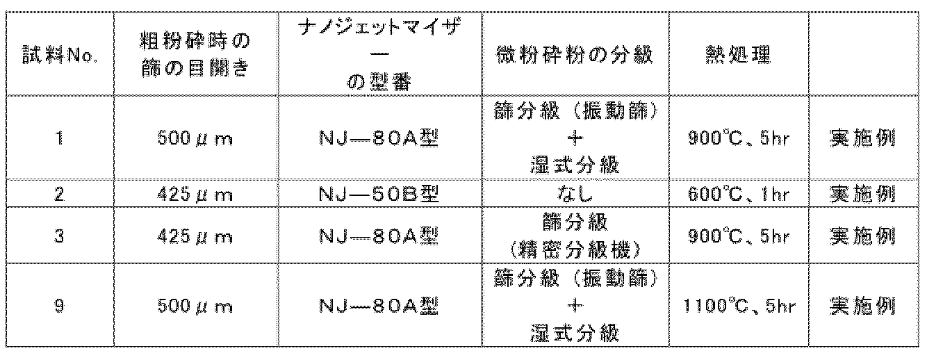
- the mixed powder was filled in a carbonaceous heat-insulating heat-resistant container with a layer of powder having a thickness of 1 mm to 80 mm on the bottom and sides so that the raw material layer thickness was more than 100 mm and 150 mm or less, and the raw material layer was further covered with a layer of powder having a thickness of 1 mm to 80 mm or less. Then, a lid made of a carbonaceous heat-insulating heat-resistant material was placed, and synthesis was performed under a nitrogen atmosphere of 0.9 MPa. After synthesis, coarse pulverization (disintegration) was performed in a mortar until the powder passed through a sieve with a predetermined opening. The openings of the sieve for each sample are shown in Table 1.
- the obtained coarsely pulverized powder was further finely pulverized using a Nano Jet Mizer (manufactured by Aisin Nano Technologies Co., Ltd.).
- a Nano Jet Mizer manufactured by Aisin Nano Technologies Co., Ltd.
- the obtained finely pulverized powder was classified by the method shown in Table 1. Sample No. 2 was not classified. Thereafter, the obtained classified powders (samples No. 1, 3, and 9) and the finely pulverized powder (sample No.
- Examples No. 5 to 7 Coarsely pulverized powders were prepared in the same manner as in the above-mentioned "Samples Nos. 1 to 3, and 9.”
- the sieve used for the coarse pulverization (disintegration) had a mesh size of 500 ⁇ m.
- the resulting coarsely pulverized powder was finely pulverized in a ball mill.
- the resulting finely pulverized powder was sieved using a vibrating sieve in the following manner, and then wet-classified to obtain silicon nitride powders having the desired D50 (samples Nos. 5 to 7).
- Example No. 8 The above-mentioned silicon nitride particles (sample No. 6) were placed in an alumina crucible and heat-treated in an air atmosphere at 900°C for 5 hours using a small powder programmable electric furnace (MMF series manufactured by AS ONE) to obtain silicon nitride powder (sample No. 8).
- MMF series small powder programmable electric furnace
- Example No. 4 a commercially available silicon nitride powder (manufactured by Aldrich, silicon nitride (predominantly ⁇ -phase, ⁇ 10 micron primary particle size, product code 248622); hereafter referred to as "Sample No. 4").
- the maximum particle size of silicon nitride particles having an L2/L1 ratio of 1% or less (the maximum particle size of single crystal particles)
- a sample for cross-sectional observation was prepared using the sample (silicon nitride particles).
- the silicon nitride particles were embedded in resin, and then the resin and silicon nitride particles were cut with a diamond cutter. Thereafter, Pt was vapor-deposited on the cross-section as a protective film, the cross-section was prepared by Ar ion milling, and the sample was fixed to the SEM sample stage with Cu double-sided tape, and SEM-EBSD measurement was performed without vapor deposition.
- the observation position was determined so that two or more silicon nitride particles were completely contained within the observation area (i.e., two or more silicon nitride particles were not in contact with the frame of the observation area).
- the measurement was performed with ⁇ -type silicon nitride particles.
- Ion milling device E-3500 (manufactured by Hitachi High-Tech Corporation)
- Ion sputtering device E-1030 (manufactured by Hitachi, Ltd.)
- Schottky scanning electron microscope SU5000 (Hitachi High-Tech Corporation)
- Backscattered electron diffraction device Velocity (manufactured by METEK Corporation)
- the total length L2 of the boundary lines was also calculated.
- the “total length L2 of the boundary lines” is the sum of the boundary lines contained inside the silicon nitride particle, and does not include the outer edge of the silicon nitride particle.
- the total length L2 of the boundary lines was calculated by adding the total length of the grain boundaries inside the silicon nitride particle and the total length of the inner walls of the cavity (if there is a cavity inside the silicon nitride particle).
- Such measurements were carried out once for 20 random silicon nitride particles, and silicon nitride particles with an L2/L1 ratio of 1% or less were regarded as single crystal particles, and the length of their major axis was measured and recorded as the "maximum particle size of the single crystal particle.” If the 20 silicon nitride particles measured contained multiple single crystal particles, the arithmetic average of their maximum particle sizes was calculated.
- the SEM images were processed using the image processing software Image J (manufactured by the National Institute of Health) to determine the aspect ratio of 20 randomly selected silicon nitride particles in the SEM images.
- the maximum diameter of the silicon nitride particle was taken as the major axis, and the particle size in the direction perpendicular to the major axis was taken as the minor axis.
- the major and minor axes were measured for 20 randomly selected silicon nitride particles, and the ratio of the minor axis to the major axis (minor axis/major axis) was determined for each particle.
- the arithmetic mean value of these ratios was taken as the average aspect ratio of the silicon nitride particles (referred to as "aspect ratio" in the table).
- the specific surface area of the sample (silicon nitride powder) was measured.
- the specific surface area of a powder (solid) was measured by gas adsorption in accordance with JIS Z 8830: 2013, using krypton as the adsorption gas.
- 1 g of silicon nitride powder was placed in a sample tube, an adsorption/desorption isotherm was obtained, and the specific surface area ( m2 /g) was calculated by the multipoint plot method.
- the surface roughness Ra was measured using a scanning probe microscope SPA300HV manufactured by Seiko Instruments Inc. The measurement conditions were as follows: Probe station/unit SPI4000/SPA300HV Cantilever: SI-DF20 Scanner: 20 ⁇ m Data type: Shape image Observation mode: DFM (Dynamic Force Mode Microscope) Scanning area: 100 nm x 100 nm Scanning frequency: 0.25Hz Analysis software: (included with the measuring device)
- Epoxy resin main agent: room temperature curing type potting resin 53 type (manufactured by Sankei Corporation) 010-8140, hardener: room temperature curing type potting resin 53 type (manufactured by Sankei Corporation) 010-8143
- a sample silicon nitride powder
- the filling rate of the silicon nitride powder in the resin composition was 50 volume %.
- a 1 mm thick aluminum plate with a rectangular hole of 1 cm x 10 cm was prepared as a mold form.
- a PET film coated with a release agent (rear side film) was attached to the rear side of the mold form so as to cover the rectangular hole, with the release agent-coated surface facing the mold form.
- a PET film coated with a release agent front side film
- Another aluminum plate was placed on top of the front side film and heated at 100°C for 1 hour to harden the composite. After curing was complete, the aluminum plate was left to cool, and when its temperature had dropped to room temperature, it was removed.
- the PET films on the front and back sides of the cured composite were then peeled off to obtain a sheet-like sample for measuring the moisture content.
- the moisture content of the obtained sheet sample was measured.
- the water content was measured based on the Karl Fischer method in accordance with JIS K 0068:2001 "Method for measuring water content in chemical products.”
- a resin composition having a water content of less than 380 ppm was evaluated as pass ( ⁇ ), and a resin composition having a water content of 380 ppm or more was evaluated as fail ( ⁇ ).
- the measurement results are discussed below.
- the silicon nitride powder of sample No. 4 which does not satisfy the requirements of this embodiment, had a high water content. Therefore, the resin composition prepared using this silicon nitride powder had a high water content.
Landscapes
- Chemical & Material Sciences (AREA)
- Organic Chemistry (AREA)
- Health & Medical Sciences (AREA)
- Chemical Kinetics & Catalysis (AREA)
- Medicinal Chemistry (AREA)
- Polymers & Plastics (AREA)
- Inorganic Chemistry (AREA)
- Ceramic Products (AREA)
Abstract
Description
放熱材料の1つとして、樹脂と無機粒子とを含む樹脂組成物があり、無機粒子としては窒化ケイ素粉末が利用できることが知られている(例えば特許文献1)。
特許文献2~3の窒化ケイ素粉末は、窒化ケイ素焼結体に用いるための窒化ケイ素粉末について開示しているため、樹脂と混合して樹脂組成物を形成することも、樹脂組成物のフィラーに適した窒化ケイ素粉末についても検討されていない。また、特許文献2~3では、窒化ケイ素粒子の水分量について検討されていない。
複数の窒化ケイ素粒子を含み、エタノールに対するRsp値が105.6未満である、窒化ケイ素粉末である。
表面粗さRaが0.97nm未満である、態様1に記載の窒化ケイ素粉末である。
窒化ケイ素粒子の比表面積相当径が0.71μm超である、態様1または2に記載の窒化ケイ素粉末である。
比表面積が2.66m2/g未満である、態様1~3のいずれか1つに記載の窒化ケイ素粉末である。
見かけ密度が3.17g/cm3超である、態様1~4のいずれか1つに記載の窒化ケイ素粉末である。
外縁の長さL1に対する内部の境界線の合計長さL2の比(L2/L1)が1%以下である窒化ケイ素粒子の最大粒径が6.8μm以上である、態様1~5のいずれか1つに記載の窒化ケイ素粉末である。
樹脂と、態様1~6のいずれか1つに記載の窒化ケイ素粉末とを含む樹脂組成物である。
本発明者らは、樹脂組成物に含まれる水分が電子部品に悪影響を及ぼし得ることから、樹脂組成物の水分量を低減するための方法を検討し、樹脂組成物のフィラーとして用いられる窒化ケイ素粉末の水分量を制御することが重要であるとの考えに至った。
発明者らは鋭意検討を行った結果、パルスMNR測定から求めることのできるRsp値、特に、エタノールに対するRsp値が、窒化ケイ素粉末の水分量の指標として適切であることを初めて見いだして、本発明を完成するに至った。
エタノールに対するRsp値は、窒化ケイ素粉末の表面に吸着された分散媒の分子(エタノール分子)の運動性に関する指標である。窒化ケイ素スラリー中に分散された窒化ケイ素粉末は、その表面に分散媒の分子を拘束した状態で、窒化ケイ素スラリー中に分散している。
ここで、窒化ケイ素粉末の表面に拘束されている分散媒の分子の数が増加すると、横緩和時間(T2)が短くなるため、Rsp値が大きくなる。また、窒化ケイ素粉末の表面に拘束されている分散媒の分子の数が増加すると、分散媒中に分散した状態が安定するため、窒化ケイ素粉末の分散性が向上する。
これらのことから、Rsp値が大きくなると、窒化ケイ素粉末の分散性が向上する傾向がある。そのため、Rsp値は、分散性の指標として利用されることがある。
つまり、エタノールに対する窒化ケイ素粉末のRsp値を105.6未満に制御することで、水分量の少ない窒化ケイ素粉末を得ることができ、その窒化ケイ素粉末を用いることで、水分量の少ない樹脂組成物を作製することができる。
Rsp値=(Rav-Rb)/Rb (1)
ここでRavは、分散媒に窒化ケイ素粉末を分散させた窒化ケイ素スラリー(例えば体積X(ml))をパルスNMR測定したときの横緩和時間の逆数である。また、Rbは、窒化ケイ素スラリーの分散媒のみ(例えば体積X(ml))を、パルスNMR測定したときの横緩和時間の逆数である。なお、分散媒(エタノール)のみからなる液体を「ブランク液」と称することがある。通常、ブランク液の体積は、パルスNMR測定時の窒化ケイ素スラリーの体積と同一にする。
窒化ケイ素粉末の表面粗さRa(算術平均粗さ)は、0.97nm未満であることが好ましい。表面粗さRaが0.97nm未満であると、窒化ケイ素粒子の表面積を低減でき、それにより窒化ケイ素粒子の表面に吸着される水分量を低減することができる。
表面粗さRaは、好ましくは0.97nm未満であり、より好ましくは0.95nm以下であり、さらに好ましくは0.93nm未満であり、よりさらに好ましくは0.90nm以下であり、より一層好ましくは0.80nm以下であり、特に好ましくは0.70nm以下である。
窒化ケイ素粒子の比表面積相当径(DBET)は、0.71μm超であることが好ましい。比表面積相当径が0.71μm超であると、単位質量あたりの窒化ケイ素粉末に含まれる窒化ケイ素粒子の個数を低減できるため、窒化ケイ素粉末に吸着される水分量を低減することができる。
DBETは、好ましくは0.71μm超であり、より好ましくは1.10μm以上であり、さらに好ましくは1.40μm以上であり、よりさらに好ましくは3.00μm以上であり、特に好ましくは8.00μm以上である。DBETの上限は特に限定されないが、例えば50μm以下であってもよく、40μm以下であってもよく、さらには30μm以下であってもよい。
DBET(μm)=6/(S×ρ) (2)
ここで、
S:窒化ケイ素粒子の比表面積(m2/g)、および
ρ:窒化ケイ素粒子の見かけ密度(g/cm3)である。
S(窒化ケイ素粒子の比表面積)は、窒化ケイ素粉末の比表面積と実質的に一致するため、後述する方法で測定した窒化ケイ素粉末の比表面積の測定結果を用いる。
ρ(窒化ケイ素粒子の見かけ密度)は、窒化ケイ素粉末の見かけ密度と実質的に一致するため、後述する方法で測定した窒化ケイ素粉末の見かけ密度の測定結果を用いる。
実施形態に係る窒化ケイ素粉末の比表面積は、JIS Z 8830:2013に基づいて、クリプトン吸着法により測定されるBET比表面積である。窒化ケイ素粉末の比表面積は、2.66m2/g未満であることが好ましく、表面に吸着する水分量を低減し得る。
窒化ケイ素粉末の比表面積は、より好ましくは2.00m2/g以下であり、更に好ましくは1.50m2/g以下であり、より更に好ましくは1.36m2/g未満であり、一層好ましくは0.50m2/g以下であり、特に好ましくは0.24m2/g以下である。比表面積の下限は特に制限されないが、例えば、0.01m2/g以上であってもよく、0.05m2/g以上であってもよい。
窒化ケイ素粉末の見かけ密度は3.17g/cm3超であることが好ましく、より好ましくは3.18g/cm3超である。これにより内部空隙の量が少ない窒化ケイ素粒子を多く含む窒化ケイ素粉末、つまり、内部に保持され得る水分量の少ない窒化ケイ素粉末が得られる。見かけ密度の上限は、例えば、3.44g/cm3である。なお、見かけ密度が高すぎないことで、樹脂と混合したときに沈降しにくく、分散させやすくなる効果が期待される。そのような効果を発揮するためには、窒化ケイ素粉末の見かけ密度は、3.30g/cm3以下であることが好ましく、より好ましくは3.25g/cm3以下である。
窒化ケイ素粉末に含まれる窒化ケイ素粒子の、長径に対する短径の平均アスペクト比が0.50超であることが好ましく、より好ましくは0.60超であり、さらに好ましくは0.65以上であり、より一層好ましくは、0.67以上である。一方で、窒化ケイ素粒子の平均アスペクト比は、0.87未満が好ましく、より好ましくは0.85以下である。
窒化ケイ素粉末に含まれる窒化ケイ素粒子のSEM画像を、画像処理ソフト(例えば、Image J(National Institute of Health製))により解析する。窒化ケイ素粒子の最大粒径(これを「長径」とする)を特定し、長径と直交する方向における粒径を「短径」とする。任意の窒化ケイ素粒子20個について長径と短径とを測定し、各粒子について、長径に対する短径の比(短径/長径)を求める。それらの比の算術平均値を窒化ケイ素粒子の平均アスペクト比とする。
窒化ケイ素粉末のβ化率は65%以上であることが好ましい。β化率は、より好ましくは70%以上であり、さらに好ましくは80%以上であり、より一層好ましくは85%以上であり、特に好ましくは90%以上である。
窒化ケイ素粒子内部の粒界および空洞が少ないほど、内部に保持され得る水分量を減らすことができる。そこで、窒化ケイ素粒子内部の粒界の含有量の指標として、外縁の長さL1に対する境界線の合計長さL2の比(L2/L1)を導入する。L1およびL2は、窒化ケイ素粒子の断面観察から求める。なお、ここで「粒界」および「境界線」とは、EBSD解析の結果、結晶方位差(斜角)が15°を超える境界(大角粒界ともいう)を意味する。
窒化ケイ素粉末は、体積基準の累積粒度分布の微粒側から累積50%の粒径D50(以下単に「D50」と記載することがある)は1.5μm以上であることが好ましく、より好ましくは2.0μm以上であり、更に好ましくは5.0μm以上であり、より更に好ましくは10.0μm以上であり、特に好ましくは30μm以上である。上限は特に限定されないが、例えば、500.0μm以下が好ましく、より好ましくは300.0μm以下であり、更に好ましくは200.0μm以下である。
本発明の実施形態に係る窒化ケイ素粉末の製造方法について説明する。
窒化ケイ素粉末は、
(1)Siを含む原料を用いて、窒素雰囲気下にて燃焼合成法により、窒化ケイ素合成体結晶を合成する工程、
(2)窒化ケイ素合成体結晶を解砕して、窒化ケイ素の粗粉砕粉を得る工程、および
(3)窒化ケイ素の粗粉砕粉を微粉砕して、窒化ケイ素の微粉砕粉を得る工程を含む。
さらに、任意で、
(4)窒化ケイ素の微粉砕粉を熱処理する工程を含んでもよい。
Siを含む原料としては、例えばSi粉末を使用する。
原料の平均粒子径D50は、例えば、2~10μmの範囲内である。これにより、酸素不純物量を抑制できるとともに燃焼速度を上昇させて合成温度を高くでき、良好な結晶成長を得ることができる。一例であるが、Siの平均粒子径D50は、5μmである。
窒化ケイ素合成体結晶は、複数の窒化ケイ素粒子が凝集した形態である。工程(2)では、窒化ケイ素合成体結晶を解砕することで、窒化ケイ素の粗粉砕粉を得る。例えば、合成体を、ハンマーミル、ディスクミル等の一般的な粗粉砕装置で、所定の目開きの篩(例えば、目開きが400μm~500μmの範囲内にある篩)を通過するまで解砕する。
窒化ケイ素の粗粉砕粉を、さらに微粉砕して窒化ケイ素の微粉砕粉を得る。微粉砕は、例えばジェットミル、ボールミルなどの微粉砕装置で行う。必要に応じて、得られた微粉砕粉を分級してもよい。分級は、篩別、湿式分級などで行うことができる。
得られた微粉砕粉を、そのまま窒化ケイ素粉末として使用してもよく、また、微粉砕粉に熱処理工程(後述する工程(4))を行ったものを窒化ケイ素粉末として使用してもよい。
任意で、窒化ケイ素の微粉砕粉を熱処理してもよい。熱処理することによって窒化ケイ素粒子の表面に酸化膜が形成されるので、窒化ケイ素粒子を化学的に安定化させる効果がある。熱処理は、例えば、大気下において、500℃以上1200℃以下で行う。熱処理時間は、熱処理温度に合わせて適宜調節することができる。熱処理時間は、例えば5時間である。
本発明の実施形態に係る窒化ケイ素粉末は、樹脂組成物用フィラーに好適である。樹脂組成物は、樹脂と、本発明の実施形態に係る窒化ケイ素粉末とを含んでいる。
なお、樹脂組成物への窒化ケイ素粉末の充填率とは、樹脂組成物(窒化ケイ素粉末を含む)の体積を100体積%としたときの、窒化ケイ素粉末の含有量(体積%)のことである。
一般的に用いられる公知の方法を使用して、窒化ケイ素粉末と樹脂を混合することにより樹脂組成物を得ることができる。例えば、樹脂が液状の場合(例えば液状エポキシ樹脂など)は、液状樹脂と窒化ケイ素粉末と硬化剤とを混合した後、熱または紫外線などで硬化させることにより樹脂組成物を得ることができる。硬化剤、混合方法、および硬化方法は公知のものおよび方法を用いることができる。一方、樹脂が固体状の場合は、窒化ケイ素粉末と樹脂を混合した後に、溶融混練などの公知の方法により混練することで目的とする樹脂組成物を得ることができる。
(試料No.1~3、9)
Si粉末(粒子径=5μm)と、希釈剤として別途準備した窒化ケイ素粉末(粒子径=1μm)とを、転動ボールミルで混合した。希釈剤の添加量は、原料全体(希釈剤を含む)に対して5~8質量%とした。層厚1mm以上80mm以下の敷粉を底面および側面に敷いた、炭素質の断熱性耐熱容器に、混合粉末を原料層厚が100mm超150mm以下になるように充填し、更に原料層上を層厚1mm以上80mm以下の敷粉で覆った。その後、炭素質の断熱性耐熱材からなる蓋をし、0.9MPaの窒素雰囲気下で合成を行った。合成後は、乳鉢にて、所定の目開きの篩を通過するまで粗粉砕(解砕)を行った。各試料における篩の目開きを表1に示す。
その後、得られた分級粉(試料No.1、3、9)、微粉砕粉(試料No.2)を、アルミナ製の坩堝に入れ、粉小型プログラム電気炉(アズワン製MMFシリーズ)を用いて、表1に記載の条件(熱処理温度、熱処理時間)で、大気雰囲気下で熱処理を行って、窒化ケイ素粉末(試料No.1~3、9)を得た。
上記の「試料No.1~3、9」と同様に、粗粉砕粉を作成した。なお、粗粉砕(解砕)時に使用した篩の目開きは500μmとした。
得られた粗粉砕粉について、ボールミルで微粉砕を行った。得られた微粉砕粉について、振動篩を用いて以下の手順で篩分級を行った後、さらに湿式分級を行い、所望のD50を有する窒化ケイ素粉末(試料No.5~7)を得た。
・試料No.5:目開き150μmの篩を用いて篩い分けた際に、篩上に残った窒化ケイ素粒子(D50は192.0μm)
・試料No.6:目開き106μmの篩を用いて篩い分けた際に、篩下に残った粉末について、更に75μmの篩を用いて篩い分け、篩上に残った窒化ケイ素粒子(D50は83.0μm)
・試料No.7:目開き63μmの篩を用いて篩い分けた際に、篩下に残った窒化ケイ素粒子(D50は22.0μm)
上述した窒化ケイ素粒子(試料No.6)を用い、アルミナ製の坩堝に入れ、粉小型プログラム電気炉(アズワン製MMFシリーズ)を用いて、大気雰囲気下で、熱処理温度900℃、熱処理時間5時間で熱処理を行って、窒化ケイ素粉末(試料No.8)を得た。
粉末X線回折装置(理学電機製)により試料(窒化ケイ素粉末)の回折パターンを取得した。測定条件は以下の通りとした。
・X線源:CuKα線
・X線出力:45kV、200mA
・グラファイトモノクロームメーター
・回折角(2θ):2~90°の範囲を0.02°刻みでステップスキャン
・走査速度:21.7deg/分
試料(窒化ケイ素粒子)を用いて断面観察用試料を作製した。断面観察用試料の作製では、窒化ケイ素粒子を樹脂包埋後、樹脂と窒化ケイ素粒子をダイヤモンドカッターにて切断した。その後、断面に保護膜としてPtを蒸着し、Arイオンミリングにて断面調製を行い、SEM試料台にCu両面テープにて固定し、無蒸着にてSEM-EBSD測定を行った。観察領域内に2つ以上の窒化ケイ素粒子が完全に入るように(つまり、2つ以上の窒化ケイ素粒子が、観察領域の枠と接触しないように)、観察位置を決定した。測定はβ型窒化ケイ素粒子で行った。
・使用機器
イオンミリング装置:E-3500(株式会社日立ハイテク製)
イオンスパッタ装置:E-1030(株式会社日立製作所製)
ショットキー走査電子顕微鏡:SU5000(株式会社日立ハイテク製)
後方散乱電子回折装置:Velocity(METEK株式会社製)
・測定領域:500.0μm×400.0μm
・加速電圧:15.0kV
・倍率:×500
・真空度:30Pa
窒化ケイ素粒子の比表面積径は、以下の式(2)から算出した。
DBET(μm)=6/(S×ρ) (2)
窒化ケイ素粒子の比表面積(m2/g)は、窒化ケイ素粉末の比表面積と実質的に一致するため、後述する「(5)比表面積」で測定した比表面積を、式(2)のSに代入した。
窒化ケイ素粒子の見かけ密度(g/cm3)は、窒化ケイ素粉末の見かけ密度と実質的に一致するため、後述する「(8)窒化ケイ素粉末の見かけ密度」で測定した見かけ密度を式(2)のρに代入した。
試料(窒化ケイ素粉末)のSEM画像を撮影した。撮影には以下の装置を使用した。
・使用機器
走査電子顕微鏡:JSM-IT200(日本電子株式会社製)
撮影条件は以下の通りとした。
加速電圧:5.0kV
信号:SED
照射電流:Std.-PC55
撮影倍率:1000倍
試料(窒化ケイ素粉末)の比表面積を測定した。
ガス吸着による粉体(固体)の比表面積測定法はJIS Z 8830:2013に準拠し、吸着ガスとしてクリプトンを用いた。測定に際し、1gの窒化ケイ素粉末をサンプル管にいれて、吸脱着等温線を取得し、多点プロット法により、比表面積(m2/g)を算出した。
表面粗さRaの測定には、セイコーインスツルメンツ社製、走査型プローブ顕微鏡SPA300HVを用いた。測定条件は下記の通りとした。
プローブステーション/ユニット SPI4000/SPA300HV
カンチレバー:SI-DF20
スキャナ:20μm
データタイプ:形状像
観察モード:DFM(ダイナミックフォースモード(Dynamic Forcee Mode Microscpoe)
走査エリア:100nm×100nm
走査周波数:0.25Hz
解析ソフト:(測定装置に付随)
試料(窒化ケイ素粉末)0.2gを分散媒(エタノール)0.3mLと混合し、試験液を準備した。この試験液の横緩和時間(T2)を、Bruker社製のパルスNMR装置「the minispec mq20」で測定した。測定条件は、共鳴周波数:20MHz、測定核:1H NMR、測定方法:T2、サンプル量:0.3ml、温度25℃であった。また、純水を用いてブランク液の横緩和時間(T2)も同様の測定条件で測定した。窒化ケイ素スラリーの横緩和時間(T2)の逆数をRav、ブランク液の横緩和時間(T2)の逆数をRbとし、以下の式(1)からRspを求めた。
Rsp値=(Rav-Rb)/Rb (1)
試料(窒化ケイ素粉末)の見かけ密度をJIS R 1620:1995に準拠して測定した。測定方法、測定条件は以下の通りとした。
・測定方法:気体置換法
・試料の乾燥:200℃、8時間以上
・使用装置:アキュピック1330(Micromeritics社)
・測定条件
パージ回数10回
パージ充填圧力:15.0psig
測定回数:5回
測定充填圧力:15.0psig
平衡圧:0.005psig/分
精度を設定しての測定:Yes
バラつき許容誤差:0.05%
試料セル寸法:10cm3
試料(窒化ケイ素粉末)の粒度分布を測定し、累積50%の粒径D50を求めた。
窒化ケイ素粉末の粒度分布は、レーザー回折法により測定を行った。水中に分散させた試料にレーザー光線を照射し、その回折を測定して粒度を求めた。測定装置はCILAS製1090L型を用いた。粒子径は円相当粒子径とした。円相当粒子径とは投影粒子画像と同じ面積となる真円の粒子径のことである。また、粒子径の基準は体積とした。
試料(窒化ケイ素粉末)の水分量を測定した。水分量は、JIS K 0068:2001「化学製品の水分測定方法」の記載に準拠してカールフィッシャー法に基づいて測定を行った。
エポキシ樹脂(主剤:常温硬化型埋込樹脂53型(三啓社製)010-8140、硬化剤:常温硬化型埋込樹脂53型(三啓社製)010-8143)と、試料(窒化ケイ素粉末)とを、50:50の配合比(体積比)で混合し、泡とり練太郎(株式会社シンキー製)を用いて攪拌混合して、エポキシ樹脂-フィラー(窒化ケイ素粉末)のコンポジットを得た。樹脂組成物への窒化ケイ素粉末の充填率は50体積%であった。
水分量は、JIS K 0068:2001「化学製品の水分測定方法」の記載に準拠してカールフィッシャー法に基づいて測定を行った。
樹脂組成物の水分量が380ppm未満を合格(〇)、380ppm以上を不合格(×)と評価した。
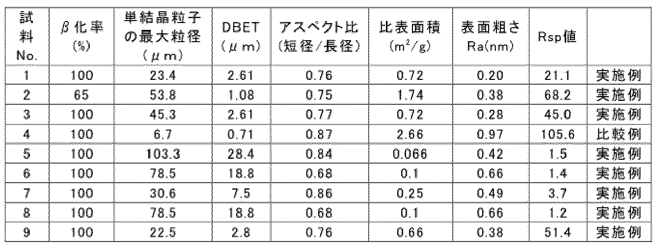
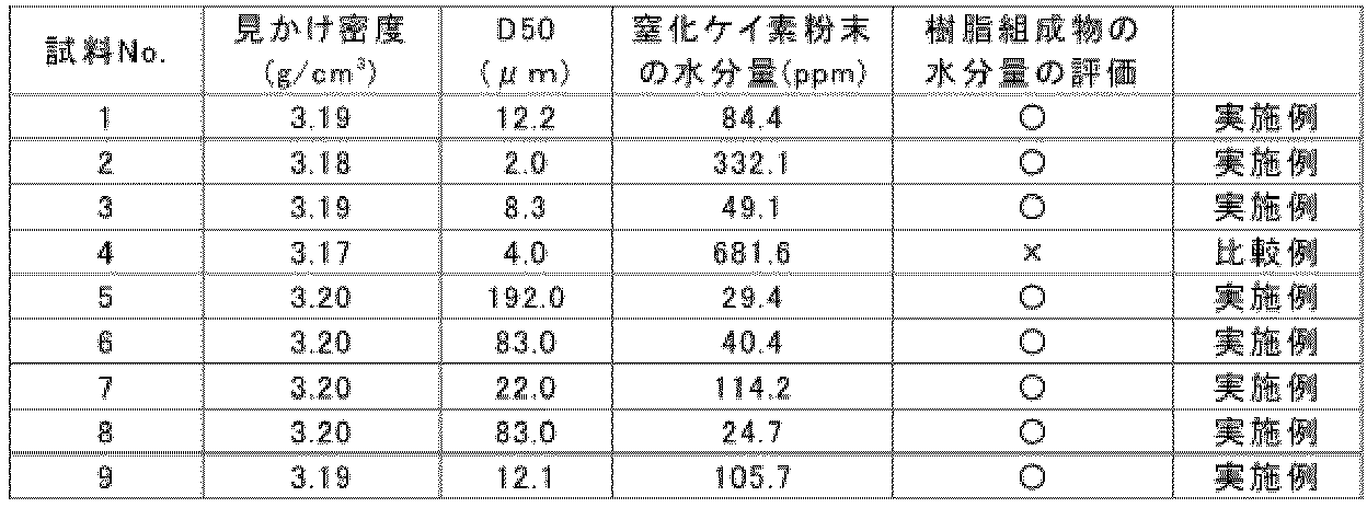
本実施形態の要件を満たす試料No.1~3および5~9の窒化ケイ素粉末は水分量が少なかった。そのため、それらの窒化ケイ素粉末を用いて作製した樹脂組成物の水分量を少なくすることができた。
一方、本実施形態の要件を満たしていない試料No.4の窒化ケイ素粉末は水分量が多かった。そのため、その窒化ケイ素粉末を用いて作製した樹脂組成物の水分量が多くなっていた。
Claims (7)
- 複数の窒化ケイ素粒子を含み、エタノールに対するRsp値が105.6未満である、窒化ケイ素粉末。
- 表面粗さRaが0.97nm未満である、請求項1に記載の窒化ケイ素粉末。
- 前記窒化ケイ素粒子の比表面積相当径が0.71μm超である、請求項1に記載の窒化ケイ素粉末。
- 比表面積が2.66m2/g未満である、請求項1に記載の窒化ケイ素粉末。
- 見かけ密度が3.17g/cm3超である、請求項1に記載の窒化ケイ素粉末。
- 外縁の長さL1に対する内部の境界線の合計長さL2の比(L2/L1)が1%以下である窒化ケイ素粒子の最大粒径が6.8μm以上である、請求項1に記載の窒化ケイ素粉末。
- 樹脂と、請求項1~6のいずれか1項に記載の窒化ケイ素粉末とを含む樹脂組成物。
Priority Applications (3)
| Application Number | Priority Date | Filing Date | Title |
|---|---|---|---|
| CN202480018140.3A CN120858074A (zh) | 2023-03-31 | 2024-02-21 | 氮化硅粉末和使用其的树脂组合物 |
| JP2025509952A JPWO2024202736A1 (ja) | 2023-03-31 | 2024-02-21 | |
| KR1020257035323A KR20250165403A (ko) | 2023-03-31 | 2024-02-21 | 질화규소 분말 및 이를 이용한 수지 조성물 |
Applications Claiming Priority (2)
| Application Number | Priority Date | Filing Date | Title |
|---|---|---|---|
| JP2023-058739 | 2023-03-31 | ||
| JP2023058739 | 2023-03-31 |
Publications (1)
| Publication Number | Publication Date |
|---|---|
| WO2024202736A1 true WO2024202736A1 (ja) | 2024-10-03 |
Family
ID=92905103
Family Applications (1)
| Application Number | Title | Priority Date | Filing Date |
|---|---|---|---|
| PCT/JP2024/006305 Ceased WO2024202736A1 (ja) | 2023-03-31 | 2024-02-21 | 窒化ケイ素粉末およびそれを用いた樹脂組成物 |
Country Status (5)
| Country | Link |
|---|---|
| JP (1) | JPWO2024202736A1 (ja) |
| KR (1) | KR20250165403A (ja) |
| CN (1) | CN120858074A (ja) |
| TW (1) | TW202500501A (ja) |
| WO (1) | WO2024202736A1 (ja) |
Citations (4)
| Publication number | Priority date | Publication date | Assignee | Title |
|---|---|---|---|---|
| JPS63274604A (ja) * | 1987-05-01 | 1988-11-11 | Nkk Corp | 窒化けい素粉末の製造方法 |
| JP2015081205A (ja) * | 2013-10-21 | 2015-04-27 | 独立行政法人産業技術総合研究所 | 窒化ケイ素フィラー、樹脂複合物、絶縁基板、半導体封止材 |
| WO2021107021A1 (ja) * | 2019-11-28 | 2021-06-03 | 株式会社トクヤマ | 窒化ケイ素焼結体の製造方法 |
| JP2022135240A (ja) * | 2021-03-05 | 2022-09-15 | 三菱マテリアル株式会社 | 窒化珪素粉末及びその製造方法並びにこれを用いたアンダーフィル材用組成物 |
Family Cites Families (3)
| Publication number | Priority date | Publication date | Assignee | Title |
|---|---|---|---|---|
| JP4089974B2 (ja) | 2004-04-27 | 2008-05-28 | 日立金属株式会社 | 窒化ケイ素質粉末、窒化ケイ素質焼結体及びこれを用いた電子部品用回路基板 |
| CN109761206A (zh) | 2019-03-18 | 2019-05-17 | 青岛瓷兴新材料有限公司 | 一种高纯低铝类球形β氮化硅粉体、其制造方法及应用 |
| CN110357052A (zh) | 2019-07-16 | 2019-10-22 | 青岛瓷兴新材料有限公司 | 一种通过金属还原制备氮化硅粉末的方法 |
-
2024
- 2024-02-21 JP JP2025509952A patent/JPWO2024202736A1/ja active Pending
- 2024-02-21 WO PCT/JP2024/006305 patent/WO2024202736A1/ja not_active Ceased
- 2024-02-21 KR KR1020257035323A patent/KR20250165403A/ko active Pending
- 2024-02-21 CN CN202480018140.3A patent/CN120858074A/zh active Pending
- 2024-02-21 TW TW113106085A patent/TW202500501A/zh unknown
Patent Citations (4)
| Publication number | Priority date | Publication date | Assignee | Title |
|---|---|---|---|---|
| JPS63274604A (ja) * | 1987-05-01 | 1988-11-11 | Nkk Corp | 窒化けい素粉末の製造方法 |
| JP2015081205A (ja) * | 2013-10-21 | 2015-04-27 | 独立行政法人産業技術総合研究所 | 窒化ケイ素フィラー、樹脂複合物、絶縁基板、半導体封止材 |
| WO2021107021A1 (ja) * | 2019-11-28 | 2021-06-03 | 株式会社トクヤマ | 窒化ケイ素焼結体の製造方法 |
| JP2022135240A (ja) * | 2021-03-05 | 2022-09-15 | 三菱マテリアル株式会社 | 窒化珪素粉末及びその製造方法並びにこれを用いたアンダーフィル材用組成物 |
Also Published As
| Publication number | Publication date |
|---|---|
| JPWO2024202736A1 (ja) | 2024-10-03 |
| TW202500501A (zh) | 2025-01-01 |
| KR20250165403A (ko) | 2025-11-25 |
| CN120858074A (zh) | 2025-10-28 |
Similar Documents
| Publication | Publication Date | Title |
|---|---|---|
| WO2020004600A1 (ja) | 塊状窒化ホウ素粒子、窒化ホウ素粉末、窒化ホウ素粉末の製造方法、樹脂組成物、及び放熱部材 | |
| JP2015081205A (ja) | 窒化ケイ素フィラー、樹脂複合物、絶縁基板、半導体封止材 | |
| EP4084060B1 (en) | Boron nitride sintered body, composite body, method for producing said boron nitride sintered body and method for producing said composite body | |
| WO2024202733A1 (ja) | 窒化ケイ素粉末およびそれを用いた樹脂組成物 | |
| TW202500501A (zh) | 氮化矽粉末及使用其的樹脂組成物 | |
| WO2024202729A1 (ja) | 窒化ケイ素粉末およびそれを用いた樹脂組成物 | |
| WO2024202726A1 (ja) | 窒化ケイ素粉末およびそれを用いた樹脂組成物 | |
| WO2024202735A1 (ja) | 窒化ケイ素粉末およびそれを用いた樹脂組成物 | |
| WO2024202734A1 (ja) | 窒化ケイ素粉末およびそれを用いた樹脂組成物 | |
| WO2024202728A1 (ja) | 窒化ケイ素粉末およびそれを用いた樹脂組成物 | |
| WO2025178081A1 (ja) | 樹脂組成物 | |
| WO2025178086A1 (ja) | 樹脂組成物 | |
| JP7343734B1 (ja) | 粉末、粉末の製造方法、及び放熱シート | |
| WO2025178089A1 (ja) | 無機粉末およびそれを用いた樹脂組成物 | |
| WO2025178088A1 (ja) | 無機粉末およびそれを用いた樹脂組成物 | |
| TW202534120A (zh) | 樹脂組成物 | |
| WO2025178082A1 (ja) | 樹脂組成物 | |
| JP3636514B2 (ja) | 六方晶bn焼結体、その製造方法及び半導体用基板 | |
| JP2024080633A (ja) | アルミナ粒子およびそれを用いた樹脂組成物 | |
| TW202436230A (zh) | 氧化鋁粒子及使用其的樹脂組成物 | |
| TW202423838A (zh) | 氧化鋁粒子及使用其的樹脂組成物 | |
| JP2026060111A (ja) | 窒化ホウ素粉末、窒化ホウ素粉末の製造方法、及び樹脂成形体 |
Legal Events
| Date | Code | Title | Description |
|---|---|---|---|
| 121 | Ep: the epo has been informed by wipo that ep was designated in this application |
Ref document number: 24778879 Country of ref document: EP Kind code of ref document: A1 |
|
| WWE | Wipo information: entry into national phase |
Ref document number: 202480018140.3 Country of ref document: CN |
|
| ENP | Entry into the national phase |
Ref document number: 2025509952 Country of ref document: JP Kind code of ref document: A |
|
| WWE | Wipo information: entry into national phase |
Ref document number: 2025509952 Country of ref document: JP |
|
| ENP | Entry into the national phase |
Ref document number: 1020257035323 Country of ref document: KR Free format text: ST27 STATUS EVENT CODE: A-0-1-A10-A15-NAP-PA0105 (AS PROVIDED BY THE NATIONAL OFFICE) |
|
| WWE | Wipo information: entry into national phase |
Ref document number: KR1020257035323 Country of ref document: KR |
|
| WWP | Wipo information: published in national office |
Ref document number: 202480018140.3 Country of ref document: CN |
|
| NENP | Non-entry into the national phase |
Ref country code: DE |
|
| 122 | Ep: pct application non-entry in european phase |
Ref document number: 24778879 Country of ref document: EP Kind code of ref document: A1 |