WO2024202465A1 - プログラム、画像処理方法及び画像処理装置 - Google Patents
プログラム、画像処理方法及び画像処理装置 Download PDFInfo
- Publication number
- WO2024202465A1 WO2024202465A1 PCT/JP2024/002128 JP2024002128W WO2024202465A1 WO 2024202465 A1 WO2024202465 A1 WO 2024202465A1 JP 2024002128 W JP2024002128 W JP 2024002128W WO 2024202465 A1 WO2024202465 A1 WO 2024202465A1
- Authority
- WO
- WIPO (PCT)
- Prior art keywords
- tomographic image
- image
- ultrasonic
- ivus
- optical coherence
- Prior art date
- Legal status (The legal status is an assumption and is not a legal conclusion. Google has not performed a legal analysis and makes no representation as to the accuracy of the status listed.)
- Ceased
Links
Images




Classifications
-
- H—ELECTRICITY
- H04—ELECTRIC COMMUNICATION TECHNIQUE
- H04N—PICTORIAL COMMUNICATION, e.g. TELEVISION
- H04N23/00—Cameras or camera modules comprising electronic image sensors; Control thereof
- H04N23/50—Constructional details
- H04N23/555—Constructional details for picking-up images in sites, inaccessible due to their dimensions or hazardous conditions, e.g. endoscopes or borescopes
-
- A—HUMAN NECESSITIES
- A61—MEDICAL OR VETERINARY SCIENCE; HYGIENE
- A61B—DIAGNOSIS; SURGERY; IDENTIFICATION
- A61B1/00—Instruments for performing medical examinations of the interior of cavities or tubes of the body by visual or photographical inspection, e.g. endoscopes; Illuminating arrangements therefor
-
- A—HUMAN NECESSITIES
- A61—MEDICAL OR VETERINARY SCIENCE; HYGIENE
- A61B—DIAGNOSIS; SURGERY; IDENTIFICATION
- A61B1/00—Instruments for performing medical examinations of the interior of cavities or tubes of the body by visual or photographical inspection, e.g. endoscopes; Illuminating arrangements therefor
- A61B1/04—Instruments for performing medical examinations of the interior of cavities or tubes of the body by visual or photographical inspection, e.g. endoscopes; Illuminating arrangements therefor combined with photographic or television appliances
- A61B1/045—Control thereof
-
- A—HUMAN NECESSITIES
- A61—MEDICAL OR VETERINARY SCIENCE; HYGIENE
- A61B—DIAGNOSIS; SURGERY; IDENTIFICATION
- A61B8/00—Diagnosis using ultrasonic, sonic or infrasonic waves
- A61B8/12—Diagnosis using ultrasonic, sonic or infrasonic waves in body cavities or body tracts, e.g. by using catheters
-
- G—PHYSICS
- G01—MEASURING; TESTING
- G01N—INVESTIGATING OR ANALYSING MATERIALS BY DETERMINING THEIR CHEMICAL OR PHYSICAL PROPERTIES
- G01N29/00—Investigating or analysing materials by the use of ultrasonic, sonic or infrasonic waves; Visualisation of the interior of objects by transmitting ultrasonic or sonic waves through the object
- G01N29/04—Analysing solids
- G01N29/048—Marking the faulty objects
-
- G—PHYSICS
- G01—MEASURING; TESTING
- G01N—INVESTIGATING OR ANALYSING MATERIALS BY DETERMINING THEIR CHEMICAL OR PHYSICAL PROPERTIES
- G01N29/00—Investigating or analysing materials by the use of ultrasonic, sonic or infrasonic waves; Visualisation of the interior of objects by transmitting ultrasonic or sonic waves through the object
- G01N29/04—Analysing solids
- G01N29/06—Visualisation of the interior, e.g. acoustic microscopy
- G01N29/0609—Display arrangements, e.g. colour displays
- G01N29/0645—Display representation or displayed parameters, e.g. A-, B- or C-Scan
-
- G—PHYSICS
- G01—MEASURING; TESTING
- G01N—INVESTIGATING OR ANALYSING MATERIALS BY DETERMINING THEIR CHEMICAL OR PHYSICAL PROPERTIES
- G01N29/00—Investigating or analysing materials by the use of ultrasonic, sonic or infrasonic waves; Visualisation of the interior of objects by transmitting ultrasonic or sonic waves through the object
- G01N29/04—Analysing solids
- G01N29/06—Visualisation of the interior, e.g. acoustic microscopy
- G01N29/0654—Imaging
- G01N29/0672—Imaging by acoustic tomography
-
- G—PHYSICS
- G01—MEASURING; TESTING
- G01N—INVESTIGATING OR ANALYSING MATERIALS BY DETERMINING THEIR CHEMICAL OR PHYSICAL PROPERTIES
- G01N29/00—Investigating or analysing materials by the use of ultrasonic, sonic or infrasonic waves; Visualisation of the interior of objects by transmitting ultrasonic or sonic waves through the object
- G01N29/22—Details, e.g. general constructional or apparatus details
- G01N29/24—Probes
- G01N29/2475—Embedded probes, i.e. probes incorporated in objects to be inspected
-
- G—PHYSICS
- G01—MEASURING; TESTING
- G01N—INVESTIGATING OR ANALYSING MATERIALS BY DETERMINING THEIR CHEMICAL OR PHYSICAL PROPERTIES
- G01N29/00—Investigating or analysing materials by the use of ultrasonic, sonic or infrasonic waves; Visualisation of the interior of objects by transmitting ultrasonic or sonic waves through the object
- G01N29/22—Details, e.g. general constructional or apparatus details
- G01N29/26—Arrangements for orientation or scanning by relative movement of the head and the sensor
- G01N29/265—Arrangements for orientation or scanning by relative movement of the head and the sensor by moving the sensor relative to a stationary material
-
- G—PHYSICS
- G01—MEASURING; TESTING
- G01N—INVESTIGATING OR ANALYSING MATERIALS BY DETERMINING THEIR CHEMICAL OR PHYSICAL PROPERTIES
- G01N29/00—Investigating or analysing materials by the use of ultrasonic, sonic or infrasonic waves; Visualisation of the interior of objects by transmitting ultrasonic or sonic waves through the object
- G01N29/22—Details, e.g. general constructional or apparatus details
- G01N29/30—Arrangements for calibrating or comparing, e.g. with standard objects
-
- H—ELECTRICITY
- H04—ELECTRIC COMMUNICATION TECHNIQUE
- H04N—PICTORIAL COMMUNICATION, e.g. TELEVISION
- H04N23/00—Cameras or camera modules comprising electronic image sensors; Control thereof
- H04N23/56—Cameras or camera modules comprising electronic image sensors; Control thereof provided with illuminating means
-
- G—PHYSICS
- G01—MEASURING; TESTING
- G01N—INVESTIGATING OR ANALYSING MATERIALS BY DETERMINING THEIR CHEMICAL OR PHYSICAL PROPERTIES
- G01N2291/00—Indexing codes associated with group G01N29/00
- G01N2291/02—Indexing codes associated with the analysed material
- G01N2291/024—Mixtures
- G01N2291/02483—Other human or animal parts, e.g. bones
Definitions
- the present invention relates to a program, an image processing method, and an image processing device.
- PCI percutaneous coronary intervention
- IVUS Intra Vascular Ultra Sound
- OCT optical coherence tomography
- Patent Document 1 discloses a catheter equipped with an IVUS sensor and an OCT sensor.
- the objective is to provide a program etc. capable of presenting IVUS images and OCT images taken at the same position.
- the present disclosure is a program that causes a computer to execute a process of acquiring a plurality of optical coherence tomographic images of a cross section of a tubular organ taken at a plurality of locations using an optical sensor in a catheter inserted into the tubular organ, acquiring an ultrasonic tomographic image of the cross section of the tubular organ using an ultrasonic sensor in the catheter without changing the insertion position of the catheter into the tubular organ after the optical coherence tomographic images are acquired, and outputting a screen that displays side by side the acquired ultrasonic tomographic images and the optical coherence tomographic image taken at the same shooting position as the ultrasonic tomographic images.
- the drive unit has a function of rotating the optical sensor and the ultrasonic sensor in a circumferential direction of the tubular organ, and further causes the computer to execute a process of identifying the circumferential shooting positions of the optical coherence tomographic image and the ultrasonic tomographic image based on the amount of circumferential rotation of the optical sensor and the ultrasonic sensor by the drive unit, and identifying an optical coherence tomographic image captured at the same shooting position as the ultrasonic tomographic image.
- the computer executes a process of acquiring an ultrasonic tomographic image of a cross section of the tubular organ using the ultrasonic sensor at the same time as acquiring the optical coherence tomographic image, outputting a screen displaying the optical coherence tomographic image and the ultrasonic tomographic image captured at the same shooting position side by side at the same time, and, when a new ultrasonic tomographic image is acquired after acquiring the optical coherence tomographic image, switching to the screen displaying the newly acquired ultrasonic tomographic image and the optical coherence tomographic image captured at the same shooting position as the ultrasonic tomographic image side by side.
- the ultrasonic longitudinal tomographic image on the screen is an image based on the ultrasonic signal received simultaneously with reception of the optical signal, and a mark indicating the imaging position in the long axis direction of the ultrasonic tomographic image being displayed is provided on the ultrasonic longitudinal tomographic image.
- the present disclosure also provides an image processing method in which a computer executes a process of acquiring a plurality of optical coherence tomographic images of a cross section of a tubular organ taken at a plurality of locations using an optical sensor in a catheter inserted into the tubular organ, acquiring an ultrasonic tomographic image of the cross section of the tubular organ using an ultrasonic sensor in the catheter without changing the insertion position of the catheter into the tubular organ after the optical coherence tomographic images are acquired, and outputting a screen displaying side-by-side the acquired ultrasonic tomographic images and the optical coherence tomographic image taken at the same imaging position as the ultrasonic tomographic images.
- the present disclosure also provides an image processing device that includes a control unit, the control unit acquiring a plurality of optical coherence tomographic images of a cross section of a tubular organ captured at a plurality of locations using an optical sensor in a catheter inserted into the tubular organ, acquiring an ultrasonic tomographic image of the cross section of the tubular organ captured using an ultrasonic sensor in the catheter without changing the insertion position of the catheter into the tubular organ after the optical coherence tomographic images are acquired, and outputting a screen that displays the acquired ultrasonic tomographic images side by side with the optical coherence tomographic image captured at the same capturing position as the ultrasonic tomographic images.
- IVUS images and OCT images taken at the same position can be presented.
- FIG. 1 is an explanatory diagram showing an example of the configuration of an image diagnostic apparatus.
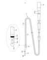
- FIG. 1 is an explanatory diagram for explaining an overview of a catheter for diagnostic imaging.
- 1 is an explanatory diagram showing a cross section of a blood vessel through which a sensor portion is inserted;
- FIG. 2 is an explanatory diagram for explaining a tomographic image.
- FIG. 2 is an explanatory diagram for explaining a tomographic image.
- FIG. 1 is a block diagram showing an example of the configuration of an image processing device.
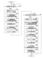
- 13 is a flowchart showing an example of a procedure for displaying a tomographic image.
- FIG. 13 is an explanatory diagram showing an example of a screen.
- FIG. 13 is an explanatory diagram showing an example of a screen.
- FIG. 1 is an explanatory diagram showing an example of a screen.
- FIG. 13 is an explanatory diagram showing an example of a screen.
- FIG. 2 is an explanatory diagram showing a configuration example of an OCT model.
- 13 is a flowchart showing an example of a display processing procedure of a tomographic image according to the second embodiment. This is an explanatory diagram of a milestone.
- 13 is a flowchart showing an example of a procedure for displaying a tomographic image according to the third embodiment.
- FIG. 13 is an explanatory diagram showing an example of a screen.
- FIG. 11 is an explanatory diagram showing another example of the screen.
- cardiac catheterization which is an intravascular treatment
- tubular organs that are the subject of catheterization are not limited to blood vessels, and may be other tubular organs such as the bile duct, pancreatic duct, bronchi, intestines, etc.
- FIG. 1 is an explanatory diagram showing an example of the configuration of an image diagnostic device 100.
- an image diagnostic device using a dual-type catheter having both functions of intravascular ultrasound (IVUS) and optical coherence tomography (OCT) will be described.
- the dual-type catheter has a mode for acquiring an ultrasonic tomographic image only by IVUS, a mode for acquiring an optical coherence tomographic image only by OCT, and a mode for acquiring both tomographic images by IVUS and OCT, and these modes can be switched for use.
- the ultrasonic tomographic image and the optical coherence tomographic image will be referred to as an IVUS image and an OCT image, respectively.
- the IVUS image and the OCT image are examples of tomographic images of a blood vessel, and each of the IVUS image and the OCT image includes a transverse cross-sectional image, which is a cross-sectional image in the radial direction of the blood vessel, and a longitudinal cross-sectional image, which is a cross-sectional image in the long axis direction of the blood vessel.
- the imaging diagnostic device 100 of this embodiment includes an intravascular examination device 101, an angiography device 102, an image processing device 3, a display device 4, and an input device 5.
- the intravascular examination device 101 includes an imaging diagnostic catheter 1 and an MDU (Motor Drive Unit) 2.
- the imaging diagnostic catheter 1 is connected to the image processing device 3 via the MDU 2.
- the display device 4 and the input device 5 are connected to the image processing device 3.
- the display device 4 is, for example, a liquid crystal display or an organic EL display
- the input device 5 is, for example, a keyboard, a mouse, a touch panel, or a microphone.
- the input device 5 and the image processing device 3 may be configured as one unit.
- the input device 5 may be a sensor that accepts gesture input, gaze input, or the like.
- the angiography device 102 is connected to the image processing device 3.
- the angiography device 102 is an angiography device that uses X-rays to photograph the blood vessels from outside the patient's body while injecting a contrast agent into the patient's blood vessels, and obtains an angiogram, which is a fluoroscopic image of the blood vessels.
- the angiography device 102 is equipped with an X-ray source and an X-ray sensor, and images an X-ray fluoroscopic image of the patient by the X-ray sensor receiving X-rays emitted from the X-ray source.
- the diagnostic imaging catheter 1 is provided with a marker that is opaque to X-rays, and the position of the diagnostic imaging catheter 1 (marker) is visualized in the angiogram.
- the angiography device 102 outputs the angiogram obtained by photographing to the image processing device 3, and displays the angiogram on the display device 4 via the image processing device 3.
- the display device 4 displays the angiogram and a tomographic image photographed using the diagnostic imaging catheter 1.
- the diagnostic imaging catheter 1 has a probe 11 and a connector section 15 disposed at the end of the probe 11.
- the probe 11 is connected to the MDU 2 via the connector section 15.
- the side of the diagnostic imaging catheter 1 far from the connector section 15 is described as the tip side, and the connector section 15 side is described as the base side.
- the probe 11 has a catheter sheath 11a, and at its tip, a guidewire insertion section 14 through which a guidewire GW can be inserted is provided.
- the guidewire insertion section 14 forms a guidewire lumen, and is used to receive a guidewire GW inserted in advance into a blood vessel and to guide the probe 11 to the affected area by the guidewire GW.
- the catheter sheath 11a forms a continuous tube section from the connection section with the guidewire insertion section 14 to the connection section with the connector section 15.
- a shaft 13 is inserted inside the catheter sheath 11a, and a sensor unit 12 is connected to the tip of the shaft 13.
- the sensor unit 12 has a housing 12d, and the tip side of the housing 12d is formed in a hemispherical shape to suppress friction and snagging with the inner surface of the catheter sheath 11a.
- an ultrasonic transmission/reception unit 12a (ultrasonic sensor, hereinafter referred to as IVUS sensor 12a) that transmits ultrasonic waves into the blood vessel and receives reflected waves from the blood vessel
- an optical transmission/reception unit 12b optical sensor, hereinafter referred to as OCT sensor 12b
- the IVUS sensor 12a is provided on the tip side of the probe 11, and the OCT sensor 12b is provided on the base end side.
- the IVUS sensor 12a and the OCT sensor 12b are attached in a direction that is approximately 90 degrees to the axial direction of the shaft 13 (the radial direction of the shaft 13) as the transmission and reception direction of ultrasonic waves or near-infrared light. It is desirable to mount the IVUS sensor 12a and the OCT sensor 12b slightly offset from the radial direction so as not to receive reflected waves or light from the inner surface of the catheter sheath 11a.
- An electrical signal cable (not shown) connected to the IVUS sensor 12a and an optical fiber cable (not shown) connected to the OCT sensor 12b are inserted into the shaft 13.
- the probe 11 is inserted into the blood vessel from the tip side.
- the sensor unit 12 and shaft 13 can move forward and backward inside the catheter sheath 11a and can also rotate in the circumferential direction.
- the sensor unit 12 and shaft 13 rotate around the central axis of the shaft 13 as the axis of rotation.
- the imaging diagnostic device 100 by using an imaging core formed by the sensor unit 12 and shaft 13, the condition inside the blood vessel is measured using IVUS images taken from inside the blood vessel and/or OCT images taken from inside the blood vessel.
- the MDU2 is a drive unit to which the probe 11 (diagnostic imaging catheter 1) is detachably attached by the connector unit 15, and controls the operation of the diagnostic imaging catheter 1 inserted into the blood vessel by driving a built-in motor in response to the operation of a medical professional. For example, the MDU2 performs a pull-back operation to rotate the sensor unit 12 and shaft 13 inserted into the probe 11 in the circumferential direction while pulling them toward the MDU2 side at a constant speed.
- the sensor unit 12 moves from the tip side to the base end and rotates by the pull-back operation, and continuously scans the inside of the blood vessel at a predetermined time interval, thereby receiving reflected waves from inside the blood vessel of the ultrasound transmitted by the IVUS sensor 12a and receiving reflected light from inside the blood vessel of the light transmitted by the OCT sensor 12b.
- the MDU2 outputs reflected wave data of the ultrasound received by the IVUS sensor 12a and reflected light data received by the OCT sensor 12b to the image processing device 3.
- the image processing device 3 acquires a signal data set which is reflected wave data (ultrasound signal) of ultrasound received by the IVUS sensor 12a via the MDU 2, and a signal data set which is reflected light data (optical signal) received by the OCT sensor 12b.
- the image processing device 3 generates ultrasound line data from the ultrasound signal data set, and constructs an IVUS transverse image (ultrasound transverse image) of a transverse layer (cross section) of a blood vessel and an IVUS longitudinal image (ultrasound longitudinal image) of a longitudinal layer (longitudinal section) of a blood vessel based on the generated ultrasound line data.
- the image processing device 3 also generates optical line data from the reflected light signal data set, and constructs an OCT transverse image (optical coherence transverse image) of a transverse layer of a blood vessel and an OCT longitudinal image (optical coherence longitudinal image) of a longitudinal layer of a blood vessel based on the generated optical line data.
- the process of generating ultrasonic line data from the ultrasonic signal data set and the process of generating optical line data from the reflected light signal data set may be executed by the MDU2 in addition to being executed by the image processing device 3.
- the image processing device 3 is configured to acquire the ultrasonic line data and optical line data from the MDU2.
- FIG. 3 is an explanatory diagram showing a cross section of a blood vessel through which the sensor unit 12 is inserted
- FIG. 4A and FIG. 4B are explanatory diagrams for explaining tomographic images.
- the imaging core rotates in the direction indicated by the arrow with the central axis of the shaft 13 as the center of rotation.
- the IVUS sensor 12a transmits and receives ultrasound at each rotation angle.
- Lines 1, 2, ... 512 indicate the transmission and reception direction of ultrasound at each rotation angle.
- the IVUS sensor 12a intermittently transmits and receives ultrasonic waves 512 times while rotating 360 degrees (one rotation) in the blood vessel.
- the IVUS sensor 12a obtains one line of data in the transmission and reception direction by transmitting and receiving ultrasonic waves once, so that 512 ultrasonic line data extending radially from the center of rotation can be obtained during one rotation.
- the 512 ultrasonic line data are dense near the center of rotation, but become sparse as they move away from the center of rotation. Therefore, the image processing device 3 can construct a two-dimensional ultrasonic tomographic image as shown on the left side of FIG. 4A by generating pixels in the empty space of each line by a known interpolation process.
- the two-dimensional ultrasonic tomographic image constructed from the 512 line data in this way is called one frame of IVUS transverse cross-sectional image.
- the sensor unit 12 scans while moving inside the blood vessel, so one frame of IVUS transverse cross-sectional image is acquired at each position of one rotation within the moving range.
- one frame of an IVUS transverse sectional image is acquired at each position from the distal end to the proximal end of the probe 11 within the range of movement, so that multiple frames of IVUS transverse sectional images are acquired within the range of movement, as shown on the right side of Figure 4A.
- the image processing device 3 can also construct a two-dimensional ultrasound tomographic image as shown in FIG. 4B by arranging the ultrasound line data received at the same rotation angle among the ultrasound line data acquired within the movement range according to the acquisition position of each line data (position in the long axis direction of the blood vessel). Specifically, the image processing device 3 constructs a two-dimensional ultrasound tomographic image from line data received at an arbitrary rotation angle (line data with the same line number) and line data received at a rotation angle obtained by adding 180 degrees to this rotation angle (line data with a line number obtained by adding 256 to the line number), and such a two-dimensional ultrasound tomographic image is called an IVUS longitudinal tomographic image.
- the OCT sensor 12b also transmits and receives near-infrared light (measurement light) at each rotation angle. Since the OCT sensor 12b also transmits and receives measurement light 512 times while rotating 360 degrees in the blood vessel, 512 optical line data extending radially from the center of rotation can be obtained during one rotation.
- the image processing device 3 can generate pixels in the empty space of each line by known interpolation processing, thereby constructing a two-dimensional OCT transverse cross-sectional image similar to the IVUS transverse cross-sectional image shown in FIG. 4A.
- the image processing device 3 can also construct a two-dimensional OCT transverse cross-sectional image similar to the IVUS transverse cross-sectional image shown in FIG. 4B from the optical line data received at an arbitrary rotation angle and the optical line data received at a rotation angle obtained by adding 180 degrees to this rotation angle.
- the diagnostic imaging catheter 1 has a marker that is opaque to X-rays in order to confirm the positional relationship between the IVUS image obtained by the IVUS sensor 12a and/or the OCT image obtained by the OCT sensor 12b, and the angio image obtained by the angiography device 102.
- the marker 14a is provided at the tip of the catheter sheath 11a, for example, at the guidewire insertion portion 14, and the marker 12c is provided on the shaft 13 side of the sensor portion 12.
- the markers 14a and 12c are provided are just an example, and the marker 12c may be provided on the shaft 13 instead of the sensor portion 12, and the marker 14a may be provided at a location other than the tip of the catheter sheath 11a.
- the IVUS sensor 12a and the OCT sensor 12b are each configured to acquire 512 lines of line data, but the number of lines of data acquired by the IVUS sensor 12a and the OCT sensor 12b is not limited to 512.
- FIG. 5 is a block diagram showing an example of the configuration of the image processing device 3.
- the image processing device 3 is a computer (information processing device) and includes a control unit 31, a main memory unit 32, an input/output unit 33, a communication unit 34, an auxiliary memory unit 35, and a reading unit 36.
- the control unit 31 is configured using one or more arithmetic processing units such as a CPU (Central Processing Unit), an MPU (Micro-Processing Unit), a GPU (Graphics Processing Unit), a GPGPU (General-purpose computing on graphics processing units), a TPU (Tensor Processing Unit), etc.
- the control unit 31 is connected to each hardware unit that constitutes the image processing device 3 via a bus. Note that when the control unit 31 has multiple arithmetic processing units, the control unit 31 may execute each process using a different arithmetic processing unit.
- the main memory unit 32 is a temporary memory area such as SRAM (Static Random Access Memory), DRAM (Dynamic Random Access Memory), or flash memory, and temporarily stores data necessary for the control unit 31 to execute arithmetic processing.
- SRAM Static Random Access Memory
- DRAM Dynamic Random Access Memory
- flash memory temporary memory area
- the input/output unit 33 has an interface to which external devices such as the intravascular inspection device 101, the angiography device 102, the display device 4, and the input device 5 are connected.
- the control unit 31 acquires ultrasonic reflected wave data and measurement light reflected light data from the intravascular inspection device 101 via the input/output unit 33, and acquires an angio image from the angiography device 102.
- the control unit 31 generates ultrasonic line data from the reflected wave data acquired from the intravascular inspection device 101, and further constructs an IVUS image.
- the control unit 31 also generates light line data from the reflected light data acquired from the intravascular inspection device 101, and further constructs an OCT image.
- the control unit 31 also displays a medical image on the display device 4 by outputting a medical image signal of an IVUS image, an OCT image, or an angio image to the display device 4 via the input/output unit 33.
- the control unit 31 also receives information input to the input device 5 via the input/output unit 33.
- the communication unit 34 has a communication interface that complies with communication standards such as 4G, 5G, and Wi-Fi.
- the image processing device 3 communicates with an external server, such as a cloud server, connected to an external network such as the Internet, via the communication unit 34.
- the control unit 31 may access the external server via the communication unit 34 and refer to various data stored in the storage of the external server.
- the control unit 31 may also cooperate with the external server to perform the processing in this embodiment, for example by performing inter-process communication.
- the auxiliary storage unit 35 is a storage device such as a hard disk or SSD (Solid State Drive).
- the auxiliary storage unit 35 stores the program P executed by the control unit 31 and various data required for the processing of the control unit 31.
- the auxiliary storage unit 35 may be an external storage device connected to the image processing device 3.
- the program P may be written to the auxiliary storage unit 35 during the manufacturing stage of the image processing device 3, or the program P may be distributed by a remote server device and acquired by the image processing device 3 via communication and stored in the auxiliary storage unit 35.
- the program P may be recorded in a readable manner on the recording medium 30 such as a magnetic disk, optical disk, or semiconductor memory, or the reading unit 36 may read it from the recording medium 30 and store it in the auxiliary storage unit 35.
- the image processing device 3 is not limited to a single computer, but may be a multi-computer including multiple computers.
- the image processing device 3 may also be a server-client system, a cloud server, or a virtual machine virtually constructed by software.
- the image processing device 3 is described as being one computer.
- an angiography device 102 that captures two-dimensional angio images is connected to the image processing device 3, but is not limited to the angiography device 102 as long as it is a device that captures images of the patient's tubular organs and the diagnostic imaging catheter 1 from multiple directions outside the body.
- FIG. 6 is a flow chart showing an example of a display processing procedure for a tomographic image
- FIGS. 7A to 8 are explanatory diagrams showing example screens.
- the control unit 31 reads out and executes a program P stored in the auxiliary storage unit 35 to generate ultrasonic line data from the reflected wave data received by the IVUS sensor 12a, and generate optical line data from the reflected light data received by the OCT sensor 12b.
- the control unit 31 also performs processing to construct an IVUS transverse cross-sectional image and an IVUS longitudinal cross-sectional image based on the ultrasonic line data, and to construct an OCT transverse cross-sectional image and an OCT longitudinal cross-sectional image based on the optical line data.
- the PCI operator performs imaging using the IVUS sensor 12a and the OCT sensor 12b at appropriate times, such as before dilating the blood vessel with a balloon catheter, after dilating the blood vessel (before placing a stent), after placing a stent, and after compressing the placed stent with a balloon catheter (post-dilation), and observes the treatment target area using the acquired tomographic images.
- the following processing may be performed at any of the above-mentioned times.
- a process is performed to acquire both ultrasound line data and optical line data while moving the imaging core by a pullback operation.
- a flush operation is performed in which a flush liquid consisting of a contrast agent, low molecular weight dextran, or saline is injected into the blood vessel to temporarily create a state where there is no blood (a state where the blood is replaced by the flush liquid). Therefore, with the OCT sensor 12b, it is difficult for the operator to check the state of the blood vessel while manually moving the observation position of the OCT sensor 12b, for example.
- the IVUS sensor 12a does not require a flash operation, for example, the operator can manually move the observation position of the IVUS sensor 12a to check (scan) the state of the blood vessel. Therefore, in PCI, in addition to a process of performing imaging by the IVUS sensor 12a and the OCT sensor 12b while performing a pullback operation (hereinafter referred to as PB processing), a process of performing imaging only by the IVUS sensor 12a (hereinafter referred to as SCAN processing) is performed.
- PB processing a process of performing imaging only by the IVUS sensor 12a
- the operator moves the sensor unit 12 to a desired position without removing the diagnostic imaging catheter 1 (without changing the insertion position in the blood vessel), and performs SCAN processing to observe the treatment target area in detail with the IVUS image.
- the image processing device 3 controls the MDU 2 according to the operator's input via the input device 5 to switch between performing PB processing and SCAN processing.
- the PB processing is not limited to a configuration in which imaging is performed using both the IVUS sensor 12a and the OCT sensor 12b, but may be a configuration in which imaging is performed only using the OCT sensor 12b.
- the control unit 31 receives operation input from the surgeon via the input device 5, and judges whether or not an instruction to perform PB processing has been received (S11). If it judges that an instruction to perform PB processing has not been received (S11: NO), it waits until it is received. If it judges that an instruction to perform PB processing has been received (S11: YES), the control unit 31 starts intravascular imaging processing (PB processing) by the intravascular inspection device 101, and acquires ultrasonic line data obtained by imaging with the IVUS sensor 12a and optical line data obtained by imaging with the OCT sensor 12b (S12).
- PB processing intravascular imaging processing
- the intravascular inspection device 101 scans the inside of the blood vessel while moving the sensor unit 12 of the diagnostic imaging catheter 1 from the tip side (distal side) to the base end side (proximal side), and acquires a series of ultrasonic line data and optical line data.
- the control unit 31 of the image processing device 3 acquires a series of ultrasonic line data and optical line data acquired by the intravascular inspection device 101 via the input/output unit 33.
- the control unit 31 acquires reflected ultrasonic wave data from the IVUS sensor 12a via the MDU2, it generates ultrasonic line data from the acquired reflected ultrasonic wave data
- the control unit 31 acquires reflected light data from the OCT sensor 12b via the MDU2
- it generates optical line data from the acquired reflected light data when the control unit 31 acquires reflected light data from the OCT sensor 12b via the MDU2, it generates optical line data from the acquired reflected light data.
- the control unit 31 constructs an IVUS transverse image and an IVUS longitudinal image based on the ultrasound line data (S13). Specifically, the control unit 31 constructs a two-dimensional IVUS transverse image by interpolating pixels for each of the 512 ultrasound line data acquired during one rotation of the sensor unit 12. The control unit 31 also extracts ultrasound line data of an arbitrary line number (ultrasound line data with the same line number) and ultrasound line data with a line number obtained by adding 256 to the line number, and arranges them in the order of the shooting position to construct a two-dimensional IVUS longitudinal image. The control unit 31 stores the constructed IVUS transverse image and IVUS longitudinal image in the main memory unit 32 or the auxiliary memory unit 35. Similarly, the control unit 31 constructs an OCT transverse image and an OCT longitudinal image based on the optical line data (S14), and stores the constructed OCT transverse image and OCT longitudinal image in the main memory unit 32 or the auxiliary memory unit 35.
- S14 optical line data
- the control unit 31 displays on the display device 4 the IVUS transverse image, IVUS longitudinal image, OCT transverse image, and OCT longitudinal image that have been constructed and stored in the main memory unit 32 or the auxiliary memory unit 35 (S15).
- the control unit 31 displays a screen as shown in FIG. 7A.
- the screen in FIG. 7A displays the OCT transverse image, OCT longitudinal image, IVUS transverse image, and IVUS longitudinal image (PB data) obtained by PB processing side by side.
- PB data IVUS longitudinal image
- the OCT transverse image and the IVUS transverse image are transverse images taken at the same position in the longitudinal direction of the blood vessel, and are images taken at the same time (simultaneously) in PB processing.
- the photographing position of this transverse image is indicated by mark L in the OCT longitudinal image and the IVUS longitudinal image.
- the control unit 31 moves the mark L on the other longitudinal tomographic image in conjunction with the mark L, and switches the displayed transverse tomographic image to a transverse tomographic image whose imaging position is the position of the mark L after the movement.
- This allows the surgeon to check the tomographic image obtained by PB processing while appropriately changing the observation position (imaging position).
- the imaging direction of the upper end side and the lower end side of the longitudinal tomographic image coincides with the imaging direction of the upper end side and the lower end side of the transverse tomographic image.
- control unit 31 rotates the other transverse tomographic image in conjunction with the mark L, and switches the displayed transverse tomographic image to a transverse tomographic image whose imaging direction is the direction of the upper end side and the lower end side of the transverse tomographic image after the rotation.
- This allows the surgeon to check the longitudinal tomographic image obtained by PB processing while appropriately changing the observation direction (imaging angle).
- the operator observes the state of the treatment target area using the OCT image and IVUS image obtained by PB processing on the screen of FIG. 7A, and if he/she wants to perform SCAN processing without removing the imaging diagnostic catheter 1, he/she issues an instruction to execute SCAN processing via the input device 5.
- the control unit 31 judges whether or not an instruction to execute SCAN processing has been received (S16), and if it judges that it has not been received (S16: NO), ends the series of processing. Note that, when the position of the mark L on the screen is moved while the screen shown in FIG.
- control unit 31 continues the processing of moving the mark L on the OCT longitudinal tomographic image and the IVUS longitudinal tomographic image and switching to the display of the OCT transverse tomographic image and the IVUS transverse tomographic image with the position of the mark L after the movement as the shooting position. Also, when the transverse tomographic image on the screen is rotated, the control unit 31 continues the processing of rotating the transverse tomographic image and switching to the display of the transverse tomographic image with the direction of the upper end side and the lower end side of the transverse tomographic image after the rotation as the shooting direction.
- the control unit 31 determines that an instruction to execute SCAN processing has been received (S16: YES)
- the control unit 31 performs intravascular imaging processing (SCAN processing) using the intravascular inspection device 101, and acquires ultrasound line data obtained by imaging using the IVUS sensor 12a (S17).
- the intravascular inspection device 101 performs imaging using the IVUS sensor 12a at a position specified by the surgeon.
- the intravascular inspection device 101 performs imaging using the IVUS sensor 12a while moving the sensor unit 12 of the diagnostic imaging catheter 1 within a range specified by the surgeon, and acquires a series of ultrasound line data.
- the control unit 31 constructs an IVUS transverse image and an IVUS longitudinal image during SCAN based on the acquired ultrasound line data (S18).
- the processing is the same as in step S13.
- the control unit 31 displays the IVUS transverse image during SCAN on the display device 4 (S19).
- the control unit 31 switches the display screen from the screen shown in FIG. 7A to the screen shown in FIG. 7B.
- the screen in FIG. 7B displays the OCT transverse image, OCT longitudinal tomographic image, and IVUS longitudinal tomographic image obtained by PB processing, and the IVUS transverse image obtained by SCAN processing.
- the OCT transverse image, OCT longitudinal tomographic image, and IVUS longitudinal tomographic image are displayed in association with information (PB data) indicating that they are tomographic images obtained by PB processing
- the IVUS transverse image is displayed in association with information (SCAN data) indicating that they are tomographic images obtained by SCAN processing. This allows the surgeon to know whether each tomographic image is PB data or SCAN data.
- the control unit 31 identifies the imaging position (SCAN position) of the IVUS transverse layer image during SCAN displayed in step S19 (S20). Since the insertion position of the imaging diagnostic catheter 1 in the blood vessel during SCAN processing has not been changed from PB processing, the control unit 31 identifies the SCAN position in the long axis direction of the blood vessel, for example, based on the initial position of the sensor unit 12 in PB processing (start position of PB processing). Specifically, the MDU 2 has a drive unit (motor) that moves the sensor unit 12 and the shaft 13 in the long axis direction of the probe 11, and obtains the SCAN position in the long axis direction of the probe 11 based on the movement distance of the sensor unit 12 by the drive unit.
- a drive unit motor
- the MDU 2 also has a long axis position sensor that measures the position of the sensor unit 12 in the long axis direction of the probe 11, and the control unit 31 may obtain the SCAN position in the long axis direction of the probe 11 measured by the long axis position sensor.
- the control unit 31 extracts and displays an OCT transverse image having the specified SCAN position as the imaging position from the OCT transverse image of the PB data acquired in step S14 (S21).
- the SCAN position is a position based on the start position of the sensor unit 12 in the PB processing, for example, so here, an OCT transverse image (PB data) having the same imaging position as the IVUS transverse image obtained by the SCAN processing is displayed.
- the control unit 31 changes the OCT transverse image in the screen of FIG. 7B to the extracted OCT transverse image.
- the control unit 31 also moves the mark L on the OCT longitudinal image and the IVUS longitudinal image to a position corresponding to the SCAN position, and displays the SCAN position on the longitudinal image (S22).
- the control unit 31 can sequentially display, on the screen of FIG. 7B, the IVUS transverse image taken at the imaging position after the movement and the OCT transverse image of the PB data taken at the same imaging position as the IVUS transverse image. Furthermore, when observation is performed without moving the sensor unit 12, the control unit 31 sequentially updates only the IVUS transverse sectional image displayed on the screen of FIG. 7B to an IVUS transverse sectional image captured at the same imaging position. This allows the IVUS transverse sectional image captured at the same imaging position to be updated and displayed, and also allows the display of the OCT transverse sectional image of the PB data captured at the same imaging position as the IVUS transverse sectional image to be continued.
- the control unit 31 may specify the imaging start direction (SCAN start direction) in the circumferential direction of the blood vessel in addition to the SCAN position in the long axis direction of the blood vessel.
- the control unit 31 specifies the imaging direction of the first ultrasound line data among the ultrasound line data acquired during one rotation in the circumferential direction of the probe 11 (circumferential direction of the blood vessel).
- the MDU 2 has a drive unit (motor) that rotates the sensor unit 12 and the shaft 13 in the circumferential direction of the probe 11, and acquires the SCAN start direction in the circumferential direction of the probe 11 based on the amount of rotation of the sensor unit 12 by the drive unit.
- the imaging direction of the line data with line number 0 may be the SCAN start direction.
- the MDU 2 has an angle sensor that measures an absolute angle as the imaging direction of the sensor unit 12 in the circumferential direction of the probe 11, and the control unit 31 may acquire the SCAN start direction from the angle measured by the angle sensor. Then, in step S21, when changing the OCT transverse image in the screen of FIG. 7B to the extracted OCT transverse image, the control unit 31 rotates and displays the OCT transverse image so that the SCAN start direction is, for example, at the upper end side.
- step S22 the control unit 31 moves the mark L on the OCT longitudinal tomographic image and the IVUS longitudinal tomographic image to a position corresponding to the SCAN position.
- the control unit 31 may construct and display the OCT longitudinal tomographic image and the IVUS longitudinal tomographic image so that the SCAN start direction is at the upper end side, and move the mark L on the OCT longitudinal tomographic image and the IVUS longitudinal tomographic image. This makes it possible to display the OCT transverse tomographic image and the OCT longitudinal tomographic image captured at the same shooting position and in the same shooting direction as the IVUS transverse tomographic image during SCAN.
- FIG. 7B may be an IVUS longitudinal tomographic image obtained by SCAN processing in addition to an IVUS longitudinal tomographic image obtained by PB processing.
- an IVUS longitudinal tomographic image of PB data may be displayed, and when an IVUS longitudinal tomographic image is generated based on ultrasound line data acquired by SCAN processing, the IVUS longitudinal tomographic image at the scan position (observation position) may be updated to the generated IVUS longitudinal tomographic image (IVUS longitudinal tomographic image of SCAN data).
- the observation position can be grasped by the IVUS longitudinal tomographic image of PB data, and as SCAN processing progresses, it becomes possible to display IVUS longitudinal tomographic images based on ultrasound line data acquired at each observation position by SCAN processing.
- the control unit 31 may display the screen shown in FIG. 8 instead of the screen in FIG. 7B.
- the screen in FIG. 8 is configured to be able to switch between displaying PB data acquired by PB processing and SCAN data acquired by SCAN processing for the IVUS transverse tomographic image and the IVUS longitudinal tomographic image. Specifically, the screen of Fig.
- PB data buttons B1 and B2 for instructing the display of an IVUS transverse image and an IVUS longitudinal image based on the ultrasound line data acquired by the PB processing
- SCAN data buttons B3 and B4 for instructing the display of an IVUS transverse image and an IVUS longitudinal image based on the ultrasound line data acquired by the SCAN processing.
- control unit 31 performs the processes of steps S21 to S22, and displays an OCT transverse image at the same shooting position as the displayed IVUS transverse image (SCAN data).
- the control unit 31 may extract and display an IVUS transverse image captured at the same shooting position and shooting direction as the OCT transverse image being displayed from the IVUS transverse image acquired in step S18.
- the PB data button B2 is operated on the screen of FIG.
- the control unit 31 constructs and displays an IVUS longitudinal tomographic image with the shooting direction being the upper end side and the lower end side of the displayed IVUS transverse image based on the ultrasound line data acquired in step S12.
- the control unit 31 constructs and displays an IVUS longitudinal tomographic image with the shooting direction being the upper end side and the lower end side of the displayed IVUS transverse image based on the ultrasound line data acquired in step S17.
- the IVUS image obtained by SCAN processing is displayed, and among the OCT images obtained by PB processing, OCT images taken at the same shooting position as the IVUS image during SCAN are displayed side by side. In other words, it is possible to align the shooting positions of the displayed OCT transverse layer image and IVUS transverse layer image in the OCT image obtained by PB processing and the IVUS image obtained by SCAN processing.
- This embodiment describes an imaging diagnostic device that, when specifying the imaging position (SCAN position) of an IVUS transverse slice image obtained by SCAN processing, corrects the SCAN position based on landmarks such as the position of a side branch of a blood vessel to be observed in PB processing and SCAN processing, the blood vessel lumen diameter, or the position where the blood vessel diameter changes.
- the imaging diagnostic device 100 of this embodiment can be realized by devices similar to the devices in the imaging diagnostic device 100 of embodiment 1, and therefore a description of similar configurations will be omitted.
- a learning model that has learned training data by, for example, machine learning is stored in the auxiliary storage unit 35 of the image processing device 3.
- the learning model is expected to be used as a program module constituting artificial intelligence software.
- the learning model performs a predetermined calculation on an input value and outputs the calculation result, and the auxiliary storage unit 35 stores data such as coefficients and thresholds of functions that define this calculation as the learning model.
- an OCT model M1 that receives an OCT transverse image as an input and recognizes the vascular lumen and vascular wall areas in the input OCT transverse image, and an IVUS model M2 that receives an IVUS transverse image obtained by SCAN processing and recognizes the vascular lumen and vascular wall areas in the input IVUS transverse image are stored in the auxiliary storage unit 35.
- a model that receives an IVUS transverse image obtained by PB processing as an input and recognizes the vascular lumen and vascular wall areas in the input IVUS transverse image may be stored in the auxiliary storage unit 35.
- a flash operation is performed to remove blood cells from the captured area.
- the IVUS model M2 may be prepared in two models, one of which inputs the IVUS transverse image obtained by the SCAN process and the other of which inputs the IVUS transverse image obtained by the PB process.
- a single IVUS model M2 may be configured to recognize the regions of the vascular lumen and vascular wall in both IVUS images by learning the training data of the IVUS transverse image obtained by the SCAN process and the training data of the IVUS transverse image obtained by the PB process.
- the OCT model M1 and the IVUS model M2 may be configured to recognize the areas of the guidewire and catheter in addition to the areas of the vascular lumen and vascular wall from the OCT transverse cross-sectional image or the IVUS transverse cross-sectional image.
- FIG. 9 is an explanatory diagram showing an example of the configuration of the OCT model M1.
- the OCT model M1 is a model that recognizes a specific object contained in an input OCT transverse layer image, and can classify objects in the image pixel by pixel, for example, by semantic segmentation.
- the OCT model M1 can be configured using an image segmentation algorithm, such as DeepLab v3+, U-Net, FCN (Fully Convolutional Network), SegNet, PSPNet (Pyramid Scene Parsing Network), or may be configured by combining multiple algorithms.
- the OCT model M1 may also be a learning model for object detection, such as YOLO (You Only Look Once), SSD (Single Shot Multi-Box Detector), or ViT (Vision Transformer).
- the OCT model M1 is trained to take one OCT transverse image as input, perform calculations to recognize the vascular lumen area and vascular wall area contained in the OCT transverse image based on the input OCT transverse image, and output information indicating the recognition result. Specifically, the OCT model M1 classifies each pixel of the input OCT transverse image into the vascular lumen area, the vascular wall area, and other areas, and outputs a classified OCT transverse image (hereinafter referred to as a label image) in which each pixel is associated with a label for each area. In the example shown in FIG. 9, the OCT model M1 outputs a label image in which pixels classified into the vascular lumen area and pixels classified into the vascular wall area are shown with different hatching, and pixels classified into other areas are shown in white.
- the OCT model M1 can be generated by machine learning using training data including a training OCT transverse image and a correct label image in which data indicating the object to be identified (here, the region of the vascular lumen and the vascular wall) is labeled for each pixel in the OCT transverse image.
- data indicating the object to be identified here, the region of the vascular lumen and the vascular wall
- a coordinate range corresponding to the region of each object and a label indicating the type of each object are added to the training OCT transverse image.
- the OCT model M1 learns to output the correct label image included in the training data when the OCT transverse image included in the training data is input.
- the OCT model M1 performs a calculation based on the input OCT transverse image and obtains a detection result in which each object (here, the region of the vascular lumen and the vascular wall) in the image is detected. More specifically, the OCT model M1 obtains as an output a label image in which a value indicating the type of classified object is labeled for each pixel in the OCT transverse image. The OCT model M1 then compares the obtained detection results (labeled image) with the range and type of each object in the correct labeled image, and optimizes parameters such as the weights (coupling coefficients) between neurons so that the two are similar. There are no particular limitations on the method of optimizing parameters, but the steepest descent method, backpropagation method, etc. can be used. In this way, when an OCT transverse layer image is input, the OCT model M1 is obtained, which outputs a labeled image showing the area of the vascular lumen and the area of the vascular wall in the input image.
- the IVUS model M2 has the same configuration as the OCT model M1 shown in FIG. 9, so a detailed description will be omitted.
- the IVUS model M2 takes an IVUS transverse image as input, classifies each pixel of the input IVUS transverse image into a vascular lumen region, a vascular wall region, and other regions, and outputs a classified IVUS transverse image (label image) in which a label for each region is associated with each pixel.
- the IVUS model M2 can be generated by machine learning using training data including a training IVUS transverse image and a correct label image in which data indicating the vascular lumen and vascular wall regions is labeled for each pixel in the IVUS transverse image.
- the learning of the OCT model M1 and the IVUS model M2 may be performed by the image processing device 3 or by another learning device.
- the trained models M1 and M2 generated by training on the other learning device are downloaded from the learning device to the image processing device 3, for example, via a network or via the recording medium 30, and stored in the auxiliary storage unit 35.
- the image processing device 3 is prepared in advance with the above-mentioned OCT model M1 and IVUS model M2, and is used for processing to detect landmarks in blood vessels captured in the acquired OCT transverse section images and IVUS transverse section images when PB processing and SCAN processing are performed.
- the landmarks detected include the position of a blood vessel (hereinafter referred to as a side branch) branching off from the blood vessel (hereinafter referred to as the main trunk) into which the diagnostic imaging catheter 1 is inserted, the position of a stenosis where the lumen diameter or blood vessel diameter of the main trunk is narrowed, the position of the distal end of the guiding catheter, etc.
- the image processing device 3 may also detect, as landmarks, the extension angle of the side branch relative to the main trunk, the position and angle of extravascular tissue such as a vein or epicardium, the position and distribution of plaque such as calcified plaque or lipid plaque, the position and distribution of lesions such as dissection or hematoma, the placement position of a device such as a stent, etc.
- FIG. 10 is a flowchart showing an example of the display processing procedure for a tomographic image in the second embodiment
- FIG. 11 is an explanatory diagram of a milestone image.
- the processing shown in FIG. 10 is the processing shown in FIG. 6 with steps S31-S32 added between steps S15 and S16, and steps S33-S35 added between steps S20 and S21. Explanations of the same steps as in FIG. 6 will be omitted.
- control unit 31 of the image processing device 3 when the control unit 31 of the image processing device 3 receives an instruction to perform PB processing (S11: YES), it executes the processes of steps S12 to S15. After acquiring OCT transverse slice images by PB processing, the control unit 31 executes segmentation for each of the series of acquired OCT transverse slice images (S31). Specifically, the control unit 31 inputs each OCT transverse slice image to the OCT model M1, and identifies the areas of the vascular lumen and vascular wall in the OCT transverse slice images based on the label image output from the OCT model M1.
- the control unit 31 extracts landmarks in the blood vessels in the OCT transverse image based on the regions of the blood vessel lumen and blood vessel wall in the OCT transverse image obtained by segmentation (S32). For example, the control unit 31 determines whether or not there is a side branch in the OCT transverse image, and if it determines that there is a side branch, extracts the branching position of the side branch as a landmark. Detection of side branches in the OCT transverse image may be performed by pattern matching using a template image generated from an OCT transverse image of a blood vessel including a side branch, or may be performed using a learning model constructed by machine learning.
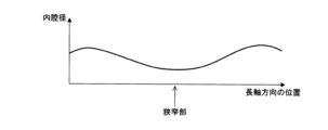
- the graph shown in FIG. 11 shows the position of the blood vessel in the longitudinal direction on the horizontal axis, and the lumen diameter of the main trunk on the vertical axis.
- the lumen diameter varies depending on the position of the blood vessel in the longitudinal direction, and a position where the lumen diameter is small indicates a stenosis and can be used as a landmark.
- a position where the lumen diameter or the blood vessel diameter changes such as a position where the lumen diameter is larger than others or a position where the ratio of the lumen diameter to the blood vessel diameter is different from others, may be used as a landmark.
- the control unit 31 calculates the lumen diameter and blood vessel diameter in the OCT transverse slice image, and extracts a position where the lumen diameter is small (stenosis), a position where the lumen diameter is large, and a position where the ratio of the lumen diameter to the blood vessel diameter is different from others as a landmark.
- the blood vessel diameter is the diameter of the blood vessel region including the blood vessel wall and the blood vessel lumen
- the lumen diameter is the diameter of the blood vessel lumen region.
- the control unit 31 can calculate the actual dimensions of the blood vessel diameter and the lumen diameter by referring to dimensional information (such as information on how many mm one pixel corresponds to) known in the image diagnostic device 100. In the output image shown in FIG.
- the control unit 31 may perform circumferential scanning using the center (or center of gravity) of each region as a reference, and calculate the maximum diameter, minimum diameter, and average diameter of the blood vessel diameter and the lumen diameter.
- control unit 31 when the control unit 31 receives an instruction to execute SCAN processing (S16: YES), it executes the processing of steps S17 to S20. After acquiring an IVUS transverse image by SCAN processing, the control unit 31 executes segmentation of the acquired IVUS transverse image (S33). Specifically, the control unit 31 inputs the IVUS transverse image to the IVUS model M2, and identifies the areas of the vascular lumen and vascular wall in the IVUS transverse image based on the label image output from the IVUS model M2.
- the control unit 31 performs the same process as in step S32, and extracts landmarks in the blood vessels in the IVUS transverse image based on the areas of the blood vessel lumen and blood vessel wall in the IVUS transverse image obtained by segmentation (S34). Note that if multiple IVUS transverse images are obtained by SCAN processing, the control unit 31 performs segmentation and extracts landmarks for each IVUS transverse image.
- the control unit 31 corrects the SCAN position identified in step S20 based on the landmark extracted from the IVUS transverse image in step S34 and the landmark extracted from the OCT transverse image in step S32 (S35). For example, the control unit 31 compares the landmark extracted in step S32 for the OCT transverse image whose shooting position is within a range of a predetermined distance in the longitudinal direction from the SCAN position identified in step S20 with the landmark extracted from the IVUS transverse image in step S34, and identifies the OCT transverse image whose landmark is most similar. The control unit 31 then determines the shooting position of the identified OCT transverse image as the SCAN position, and corrects (modifies) the SCAN position identified in step S20 to the SCAN position determined here.
- the selection of the OCT transverse image captured at the same shooting position as the IVUS transverse image obtained by the SCAN process may be performed manually by the operator.
- the control unit 31 switches the OCT transverse sectional image to be displayed according to the operation input from the surgeon received via the input device 5, making it possible to display an IVUS transverse sectional image and an OCT transverse sectional image captured at the same position.
- control unit 31 may also correct the imaging start direction (SCAN start direction) in the circumferential direction of the blood vessel.
- the control unit 31 rotates one or both of the transverse slice images so that the positions of the landmarks in the two transverse slice images match or approximate each other based on the landmarks extracted from the OCT transverse slice image in step S32 and the landmarks extracted from the IVUS transverse slice image in step S34.
- the surgeon may compare the two transverse slice images via a screen displaying the OCT transverse slice image and the IVUS transverse slice image captured at the same position in the longitudinal direction, and manually align the circumferential direction.
- control unit 31 rotates the transverse slice image that is instructed to rotate according to the operation input from the surgeon received via the input device 5, and also rotates the other transverse slice image in conjunction with the rotation. Furthermore, the control unit 31 switches the longitudinal slice image being displayed on the screen to a longitudinal slice image whose imaging direction is the direction of the upper end side and the lower end side of the transverse slice image after rotation. This makes it possible to display an OCT transverse image and an OCT longitudinal image taken at the same position and in the same direction as the IVUS transverse image during SCAN. The control unit 31 executes the processes of steps S21 to S22 based on the corrected SCAN position.
- the imaging positions of the OCT transverse layer image and the IVUS transverse layer image to be displayed can be aligned in the OCT image obtained by the PB processing and the IVUS image obtained by the SCAN processing.
- the SCAN position determined based on the movement distance of the sensor unit 12 by the MDU2 or the position measured by the long axis position sensor of the MDU2 can be corrected (adjusted) based on the landmarks of the blood vessels captured in the OCT image and the IVUS image, thereby enabling more accurate alignment.
- the shaft 13 has elasticity, it may bend in the long axis direction, and when it is bent, the position in the long axis direction cannot be accurately determined.
- the imaging positions of the OCT transverse layer image and the IVUS transverse layer image to be displayed can be more accurately aligned.
- a processing of extracting landmarks from an OCT image e.g., an OCT transverse image
- an IVUS image e.g., an IVUS transverse image
- the imaging positions in the OCT transverse image obtained by PB processing and the IVUS transverse image obtained by SCAN processing can be aligned based on the position of the landmark extracted from the IVUS transverse image.
- the image processing device 3 locally performs the process of extracting landmarks in the image by performing segmentation on the OCT transverse sectional image using the OCT model M1, and the process of extracting landmarks in the image by performing segmentation on the IVUS transverse sectional image using the IVUS model M2, but is not limited to this configuration.
- a server may be provided that performs the process of extracting landmarks in the image using the OCT model M1.
- the image processing device 3 is configured to transmit the OCT transverse sectional image obtained by the PB processing to the server, and to obtain information indicating the positions of the landmarks extracted from the OCT transverse sectional image at the server.
- a server may be provided that performs the process of extracting landmarks in the image using the IVUS model M2.
- the image processing device 3 is configured to transmit the IVUS transverse sectional image obtained by the SCAN processing to the server, and to obtain information indicating the positions of the landmarks extracted from the IVUS transverse sectional image at the server. Even with such a configuration, the same process as in this embodiment is possible, and the same effect can be obtained. Note that the modifications described in the first embodiment above can also be applied to this embodiment as appropriate.
- the OCT transverse section image and the IVUS transverse section image captured at the same imaging position can be displayed side by side in the OCT image obtained by the PB processing and the IVUS image obtained by the SCAN processing.
- the images displayed side by side are not limited to the OCT transverse section image and the OCT longitudinal section image constructed from the light line data and the IVUS transverse section image and the IVUS longitudinal section image constructed from the ultrasound line data as shown in Figs. 7A to 8.
- an imaging diagnostic device that estimates the vascular lumen diameter and the vascular diameter (the inner diameter of the hollow organ) of the imaging target based on the OCT transverse section image and/or the IVUS transverse section image, creates an estimated image of the vascular longitudinal section image based on the estimated vascular lumen diameter and the vascular diameter, and displays the created estimated vascular image.
- the imaging diagnostic device 100 of this embodiment can be realized by the same devices as those in the imaging diagnostic device 100 of the first embodiment, and therefore the description of the same configuration is omitted.
- FIG. 12 is a flowchart showing an example of the display processing procedure for a tomographic image in embodiment 3, and FIG. 13 is an explanatory diagram showing an example screen.
- the processing shown in FIG. 12 is the processing shown in FIG. 6 with steps S41 to S45 added instead of step S15. Explanations of the same steps as in FIG. 6 will be omitted. Steps S16 to S22 in FIG. 6 are not shown in FIG. 12.
- the control unit 31 of the image processing device 3 when the control unit 31 of the image processing device 3 receives an instruction to perform PB processing (S11: YES), it executes the processing of steps S12 to S14.
- the control unit 31 estimates the vascular lumen diameter and vascular diameter at the shooting position (shooting location) of each IVUS transverse image based on the acquired IVUS transverse image (S41). For example, the control unit 31 inputs the IVUS transverse image to the IVUS model M2 described in embodiment 2, and identifies the areas of the vascular lumen and vascular wall in the IVUS transverse image based on the label image output from the IVUS model M2.
- the control unit 31 calculates the average value of the vascular lumen diameter and the average value of the vascular diameter.
- the control unit 31 calculates the average value of the vascular lumen diameter and the average value of the vascular diameter for each of the IVUS transverse slice images acquired by the PB processing, and generates an estimated image of the longitudinal slice of the blood vessel (estimated blood vessel image) based on the average value of the vascular lumen diameter and the average value of the vascular diameter at each imaging position (S42).
- control unit 31 may calculate the cross-sectional area of the blood vessel lumen and the blood vessel instead of the average value of the blood vessel lumen diameter and the blood vessel diameter, and generate an estimated blood vessel image that represents the blood vessel lumen and the blood vessel by a circle having the calculated cross-sectional area of the blood vessel lumen and the blood vessel.
- the control unit 31 estimates the vascular lumen diameter and vascular diameter at the shooting position (shooting location) of each OCT transverse slice image based on the acquired OCT transverse slice images (S43).
- the control unit 31 calculates the average vascular lumen diameter and the average vascular diameter for each OCT transverse slice image acquired by PB processing, and generates an estimated image of the longitudinal section of the blood vessel (estimated blood vessel image) based on the average vascular lumen diameter and the average vascular diameter at each shooting position (S44).
- control unit 31 may calculate the cross-sectional area of the blood vessel lumen and blood vessel instead of the average values of the blood vessel lumen and blood vessel diameter, and generate an estimated blood vessel image in which the blood vessel lumen and blood vessel are represented by a circle having the calculated cross-sectional area of the blood vessel lumen and blood vessel.
- the control unit 31 displays on the display device 4 the IVUS transverse image and the IVUS longitudinal image constructed in step S13, the OCT transverse image and the OCT longitudinal image constructed in step S14, the estimated blood vessel image generated from the IVUS transverse image in step S42, and the estimated blood vessel image generated from the OCT transverse image in step S44 (S45). After that, the control unit 31 performs the processes from step S16 onward.
- the control unit 31 may display a screen in which an estimated vascular image generated from an IVUS transverse image and an estimated vascular image generated from an OCT transverse image are added to the screen of FIG. 7B or FIG. 8. This allows an estimated vascular image based on the vascular lumen diameter and vascular diameter estimated from the OCT transverse image and the IVUS transverse image to be displayed as a longitudinal image in addition to the OCT transverse image and the IVUS transverse image obtained by PB processing.
- the estimated vascular image generated from the IVUS transverse image may be an estimated vascular image generated from an IVUS transverse image sequentially obtained by SCAN processing, in addition to the estimated vascular image generated from the IVUS transverse image obtained by PB processing.
- an estimated vascular image an estimated image of the longitudinal section of the blood vessel based on the IVUS transverse section image acquired by SCAN processing is generated and displayed.
- the configuration of this embodiment is applicable to the imaging diagnostic device 100 of the above-mentioned embodiments 1 and 2, and even when applied to the imaging diagnostic device 100 of embodiments 1 and 2, the same processes as those of embodiments 1 and 2 are possible, except for the process of generating and displaying an estimated blood vessel image, and similar effects can be obtained. Furthermore, the modified examples described as appropriate in the above-mentioned embodiments 1 and 2 can also be applied to this embodiment.
- the control unit 31 of the image processing device 3 may display an angio image of the blood vessel of the treatment target captured by the angiography device 102 in addition to the IVUS transverse image and IVUS longitudinal image constructed in step S13 and the OCT transverse image and OCT longitudinal image constructed in step S14.
- the screen of FIG. 14 displays an angio image in addition to the configuration of the screen of FIG. 7A, but the control unit 31 may display a screen in which an angio image is added to the screen of FIG. 7B or FIG. 8.
- the control unit 31 of the image processing device 3 may combine the screen of FIG. 13 and the screen of FIG.
- the screens of Figures 13 and 14 may display the vascular lumen diameter, vascular diameter, and extent of the plaque area (e.g., circumferential extent of the blood vessel) at the SCAN location.
- the surgeon can check the condition of the treatment target from the displayed images, and can more accurately grasp the condition of the treatment target from the estimated vascular lumen diameter, vascular diameter, and plaque area.
- an IVUS sensor 12a that uses ultrasound to capture tomographic images inside a blood vessel and an OCT sensor 12b that uses near-infrared light to capture tomographic images inside a blood vessel are used, but the configuration is not limited to this.
- various sensors that can observe the state of blood vessels can be used, such as a sensor that receives Raman scattered light from inside the blood vessel to capture tomographic images inside the blood vessel, or a sensor that receives excitation light from inside the blood vessel to capture tomographic images inside the blood vessel.
Landscapes
- Physics & Mathematics (AREA)
- Life Sciences & Earth Sciences (AREA)
- Health & Medical Sciences (AREA)
- General Health & Medical Sciences (AREA)
- Pathology (AREA)
- Chemical & Material Sciences (AREA)
- Analytical Chemistry (AREA)
- Biochemistry (AREA)
- General Physics & Mathematics (AREA)
- Immunology (AREA)
- Engineering & Computer Science (AREA)
- Acoustics & Sound (AREA)
- Surgery (AREA)
- Signal Processing (AREA)
- Multimedia (AREA)
- Biophysics (AREA)
- Radiology & Medical Imaging (AREA)
- Nuclear Medicine, Radiotherapy & Molecular Imaging (AREA)
- Biomedical Technology (AREA)
- Heart & Thoracic Surgery (AREA)
- Medical Informatics (AREA)
- Molecular Biology (AREA)
- Animal Behavior & Ethology (AREA)
- Public Health (AREA)
- Veterinary Medicine (AREA)
- Optics & Photonics (AREA)
- Ultra Sonic Daignosis Equipment (AREA)
- Endoscopes (AREA)
Priority Applications (2)
| Application Number | Priority Date | Filing Date | Title |
|---|---|---|---|
| JP2025509805A JPWO2024202465A1 (https=) | 2023-03-28 | 2024-01-25 | |
| US19/342,345 US20260029380A1 (en) | 2023-03-28 | 2025-09-26 | Imaging system, method, and image processing apparatus |
Applications Claiming Priority (2)
| Application Number | Priority Date | Filing Date | Title |
|---|---|---|---|
| JP2023-052326 | 2023-03-28 | ||
| JP2023052326 | 2023-03-28 |
Related Child Applications (1)
| Application Number | Title | Priority Date | Filing Date |
|---|---|---|---|
| US19/342,345 Continuation US20260029380A1 (en) | 2023-03-28 | 2025-09-26 | Imaging system, method, and image processing apparatus |
Publications (1)
| Publication Number | Publication Date |
|---|---|
| WO2024202465A1 true WO2024202465A1 (ja) | 2024-10-03 |
Family
ID=92904915
Family Applications (1)
| Application Number | Title | Priority Date | Filing Date |
|---|---|---|---|
| PCT/JP2024/002128 Ceased WO2024202465A1 (ja) | 2023-03-28 | 2024-01-25 | プログラム、画像処理方法及び画像処理装置 |
Country Status (3)
| Country | Link |
|---|---|
| US (1) | US20260029380A1 (https=) |
| JP (1) | JPWO2024202465A1 (https=) |
| WO (1) | WO2024202465A1 (https=) |
Citations (6)
| Publication number | Priority date | Publication date | Assignee | Title |
|---|---|---|---|---|
| JP2010011964A (ja) * | 2008-07-02 | 2010-01-21 | Toshiba Corp | 医用画像処理装置および医用画像処理プログラム |
| JP2012521852A (ja) * | 2009-03-31 | 2012-09-20 | ボストン サイエンティフィック サイムド,インコーポレイテッド | 複数の引戻し速度を有する血管内画像化システムを作成し使用するためのシステム及び方法 |
| WO2014049641A1 (ja) * | 2012-09-26 | 2014-04-03 | テルモ株式会社 | 画像診断装置及び情報処理装置並びにそれらの制御方法 |
| WO2016152624A1 (ja) * | 2015-03-24 | 2016-09-29 | テルモ株式会社 | 画像診断装置及びその制御方法、プログラム及びコンピュータ可読記憶媒体 |
| JP2018075080A (ja) * | 2016-11-07 | 2018-05-17 | テルモ株式会社 | 画像診断装置、画像診断装置の制御方法およびプログラム |
| JP2022146621A (ja) * | 2021-03-22 | 2022-10-05 | テルモ株式会社 | コンピュータプログラム、画質改善学習モデル、学習モデル生成方法、画像処理方法及び画像処理装置 |
-
2024
- 2024-01-25 JP JP2025509805A patent/JPWO2024202465A1/ja active Pending
- 2024-01-25 WO PCT/JP2024/002128 patent/WO2024202465A1/ja not_active Ceased
-
2025
- 2025-09-26 US US19/342,345 patent/US20260029380A1/en active Pending
Patent Citations (6)
| Publication number | Priority date | Publication date | Assignee | Title |
|---|---|---|---|---|
| JP2010011964A (ja) * | 2008-07-02 | 2010-01-21 | Toshiba Corp | 医用画像処理装置および医用画像処理プログラム |
| JP2012521852A (ja) * | 2009-03-31 | 2012-09-20 | ボストン サイエンティフィック サイムド,インコーポレイテッド | 複数の引戻し速度を有する血管内画像化システムを作成し使用するためのシステム及び方法 |
| WO2014049641A1 (ja) * | 2012-09-26 | 2014-04-03 | テルモ株式会社 | 画像診断装置及び情報処理装置並びにそれらの制御方法 |
| WO2016152624A1 (ja) * | 2015-03-24 | 2016-09-29 | テルモ株式会社 | 画像診断装置及びその制御方法、プログラム及びコンピュータ可読記憶媒体 |
| JP2018075080A (ja) * | 2016-11-07 | 2018-05-17 | テルモ株式会社 | 画像診断装置、画像診断装置の制御方法およびプログラム |
| JP2022146621A (ja) * | 2021-03-22 | 2022-10-05 | テルモ株式会社 | コンピュータプログラム、画質改善学習モデル、学習モデル生成方法、画像処理方法及び画像処理装置 |
Also Published As
| Publication number | Publication date |
|---|---|
| JPWO2024202465A1 (https=) | 2024-10-03 |
| US20260029380A1 (en) | 2026-01-29 |
Similar Documents
| Publication | Publication Date | Title |
|---|---|---|
| JP2022119785A (ja) | 血管内画像化システムインターフェイス及び影検出方法 | |
| US20240013385A1 (en) | Medical system, method for processing medical image, and medical image processing apparatus | |
| JP7489882B2 (ja) | コンピュータプログラム、画像処理方法及び画像処理装置 | |
| JP2017131348A (ja) | 画像表示装置およびその制御方法、x線不透過マーカ検出方法 | |
| US12518382B2 (en) | Medical system, method for processing medical image, and medical image processing apparatus | |
| WO2021193015A1 (ja) | プログラム、情報処理方法、情報処理装置及びモデル生成方法 | |
| JP6794226B2 (ja) | 画像診断装置、画像診断装置の作動方法およびプログラム | |
| CN114650778A (zh) | 诊断支援装置、诊断支援系统以及诊断支援方法 | |
| US20240013434A1 (en) | Program, information processing method, and information processing device | |
| JP7561833B2 (ja) | コンピュータプログラム、情報処理方法及び情報処理装置 | |
| WO2023189308A1 (ja) | コンピュータプログラム、画像処理方法及び画像処理装置 | |
| WO2023054467A1 (ja) | モデル生成方法、学習モデル、コンピュータプログラム、情報処理方法及び情報処理装置 | |
| WO2024202465A1 (ja) | プログラム、画像処理方法及び画像処理装置 | |
| US12283048B2 (en) | Diagnosis support device, diagnosis support system, and diagnosis support method | |
| JP7607482B2 (ja) | コンピュータプログラム、画質改善学習モデル、学習モデル生成方法、画像処理方法及び画像処理装置 | |
| US20240008849A1 (en) | Medical system, method for processing medical image, and medical image processing apparatus | |
| JP2024139509A (ja) | プログラム、画像処理方法、画像処理装置及びモデル生成方法 | |
| WO2023132332A1 (ja) | コンピュータプログラム、画像処理方法及び画像処理装置 | |
| JP2024142137A (ja) | プログラム、画像処理方法及び画像処理装置 | |
| WO2022209705A1 (ja) | プログラム、画像処理方法及び画像処理装置 | |
| JP2024140944A (ja) | プログラム、画像処理方法、画像処理装置及びモデル生成方法 | |
| JP7813276B2 (ja) | コンピュータプログラム、情報処理方法及び情報処理装置 | |
| US20250221624A1 (en) | Image diagnostic system, image diagnostic method, and storage medium | |
| US20250248664A1 (en) | Image diagnostic system and method | |
| JP7597626B2 (ja) | プログラム、画像処理方法、画像処理装置及びモデル生成方法 |
Legal Events
| Date | Code | Title | Description |
|---|---|---|---|
| 121 | Ep: the epo has been informed by wipo that ep was designated in this application |
Ref document number: 24778611 Country of ref document: EP Kind code of ref document: A1 |
|
| WWE | Wipo information: entry into national phase |
Ref document number: 2025509805 Country of ref document: JP |
|
| NENP | Non-entry into the national phase |
Ref country code: DE |
|
| 122 | Ep: pct application non-entry in european phase |
Ref document number: 24778611 Country of ref document: EP Kind code of ref document: A1 |