WO2024202069A1 - 表示方法、情報処理装置及び表示プログラム - Google Patents
表示方法、情報処理装置及び表示プログラム Download PDFInfo
- Publication number
- WO2024202069A1 WO2024202069A1 PCT/JP2023/013725 JP2023013725W WO2024202069A1 WO 2024202069 A1 WO2024202069 A1 WO 2024202069A1 JP 2023013725 W JP2023013725 W JP 2023013725W WO 2024202069 A1 WO2024202069 A1 WO 2024202069A1
- Authority
- WO
- WIPO (PCT)
- Prior art keywords
- care
- medical
- index value
- hospital
- display
- Prior art date
- Legal status (The legal status is an assumption and is not a legal conclusion. Google has not performed a legal analysis and makes no representation as to the accuracy of the status listed.)
- Ceased
Links
Images











Classifications
-
- G—PHYSICS
- G06—COMPUTING OR CALCULATING; COUNTING
- G06F—ELECTRIC DIGITAL DATA PROCESSING
- G06F3/00—Input arrangements for transferring data to be processed into a form capable of being handled by the computer; Output arrangements for transferring data from processing unit to output unit, e.g. interface arrangements
- G06F3/01—Input arrangements or combined input and output arrangements for interaction between user and computer
- G06F3/048—Interaction techniques based on graphical user interfaces [GUI]
- G06F3/0481—Interaction techniques based on graphical user interfaces [GUI] based on specific properties of the displayed interaction object or a metaphor-based environment, e.g. interaction with desktop elements like windows or icons, or assisted by a cursor's changing behaviour or appearance
- G06F3/0482—Interaction with lists of selectable items, e.g. menus
-
- G—PHYSICS
- G16—INFORMATION AND COMMUNICATION TECHNOLOGY [ICT] SPECIALLY ADAPTED FOR SPECIFIC APPLICATION FIELDS
- G16H—HEALTHCARE INFORMATICS, i.e. INFORMATION AND COMMUNICATION TECHNOLOGY [ICT] SPECIALLY ADAPTED FOR THE HANDLING OR PROCESSING OF MEDICAL OR HEALTHCARE DATA
- G16H10/00—ICT specially adapted for the handling or processing of patient-related medical or healthcare data
-
- G—PHYSICS
- G16—INFORMATION AND COMMUNICATION TECHNOLOGY [ICT] SPECIALLY ADAPTED FOR SPECIFIC APPLICATION FIELDS
- G16H—HEALTHCARE INFORMATICS, i.e. INFORMATION AND COMMUNICATION TECHNOLOGY [ICT] SPECIALLY ADAPTED FOR THE HANDLING OR PROCESSING OF MEDICAL OR HEALTHCARE DATA
- G16H40/00—ICT specially adapted for the management or administration of healthcare resources or facilities; ICT specially adapted for the management or operation of medical equipment or devices
- G16H40/20—ICT specially adapted for the management or administration of healthcare resources or facilities; ICT specially adapted for the management or operation of medical equipment or devices for the management or administration of healthcare resources or facilities, e.g. managing hospital staff or surgery rooms
-
- G—PHYSICS
- G16—INFORMATION AND COMMUNICATION TECHNOLOGY [ICT] SPECIALLY ADAPTED FOR SPECIFIC APPLICATION FIELDS
- G16H—HEALTHCARE INFORMATICS, i.e. INFORMATION AND COMMUNICATION TECHNOLOGY [ICT] SPECIALLY ADAPTED FOR THE HANDLING OR PROCESSING OF MEDICAL OR HEALTHCARE DATA
- G16H40/00—ICT specially adapted for the management or administration of healthcare resources or facilities; ICT specially adapted for the management or operation of medical equipment or devices
- G16H40/60—ICT specially adapted for the management or administration of healthcare resources or facilities; ICT specially adapted for the management or operation of medical equipment or devices for the operation of medical equipment or devices
- G16H40/67—ICT specially adapted for the management or administration of healthcare resources or facilities; ICT specially adapted for the management or operation of medical equipment or devices for the operation of medical equipment or devices for remote operation
-
- G—PHYSICS
- G06—COMPUTING OR CALCULATING; COUNTING
- G06Q—INFORMATION AND COMMUNICATION TECHNOLOGY [ICT] SPECIALLY ADAPTED FOR ADMINISTRATIVE, COMMERCIAL, FINANCIAL, MANAGERIAL OR SUPERVISORY PURPOSES; SYSTEMS OR METHODS SPECIALLY ADAPTED FOR ADMINISTRATIVE, COMMERCIAL, FINANCIAL, MANAGERIAL OR SUPERVISORY PURPOSES, NOT OTHERWISE PROVIDED FOR
- G06Q50/00—Information and communication technology [ICT] specially adapted for implementation of business processes of specific business sectors, e.g. utilities or tourism
- G06Q50/10—Services
- G06Q50/22—Social work or social welfare, e.g. community support activities or counselling services
-
- G—PHYSICS
- G16—INFORMATION AND COMMUNICATION TECHNOLOGY [ICT] SPECIALLY ADAPTED FOR SPECIFIC APPLICATION FIELDS
- G16H—HEALTHCARE INFORMATICS, i.e. INFORMATION AND COMMUNICATION TECHNOLOGY [ICT] SPECIALLY ADAPTED FOR THE HANDLING OR PROCESSING OF MEDICAL OR HEALTHCARE DATA
- G16H50/00—ICT specially adapted for medical diagnosis, medical simulation or medical data mining; ICT specially adapted for detecting, monitoring or modelling epidemics or pandemics
- G16H50/20—ICT specially adapted for medical diagnosis, medical simulation or medical data mining; ICT specially adapted for detecting, monitoring or modelling epidemics or pandemics for computer-aided diagnosis, e.g. based on medical expert systems
Definitions
- the present invention relates to a display method, an information processing device, and a display program.
- policy flow graph which diagrams the process of assigning the objects that are the targets of policies in various fields such as medical care, nursing care, and administration, such as users, to services that will achieve the goals of the policies.
- the following insurance and medical data analysis system has been proposed as one technology to support the evaluation of such policies.
- the insurance and medical data analysis system calculates vector information from nationwide (first group) health care data, and generates model information (prediction model) from this vector information and the vector information of the healthcare data for the policies and measures implemented in a specific region (second group).
- model information prediction model
- the service route to which a user is assigned in the policy flow graph changes depending on the condition branch, and is not necessarily the same.
- the combination of individual medical institutions that work together as a patient moves from the acute phase through the recovery phase and back home depends on which medical institution the patient is assigned to in the condition branch of each medical function in the policy flow graph.
- the present invention aims to provide a display method, information processing device, and display program that can improve the visibility of service routes.
- the computer executes a process of acquiring an index value and route information related to the user from a storage unit, and displaying on the screen a path that highlights the route of the user and the index value of the user based on the acquired route information.
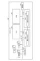
- FIG. 1 is a block diagram illustrating an example of a functional configuration of a server device.
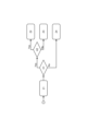
- FIG. 2 is a diagram illustrating a flow graph of a policy.
- FIG. 3 is a diagram showing a specific example of a flow graph of a policy.
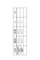
- FIG. 4 is a diagram showing an example of medical institution list data.
- FIG. 5 is a diagram showing a detailed example of a medical institution list.
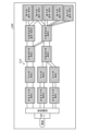
- FIG. 6 is a diagram (1) showing an example of a care pathway display.
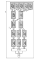
- FIG. 7 is a diagram (2) showing an example of a care pathway display.
- FIG. 8 is a diagram (3) showing an example of a care pathway display.
- FIG. 9 is a diagram showing an example of a graph showing the number of days of hospitalization.
- FIG. 9 is a diagram showing an example of a graph showing the number of days of hospitalization.
- FIG. 10 is a diagram showing an example of a bed occupancy rate graph.
- FIG. 11 is a diagram showing an example of the care path selection screen.
- FIG. 12 is a diagram showing an example of the care path selection screen.
- FIG. 13 is a diagram (4) showing an example of a care pathway display.
- FIG. 14 is a diagram showing an example of a radar chart.
- FIG. 15 is a diagram (5) showing an example of a care pathway display.
- FIG. 16 is a diagram (6) showing an example of a care pathway display.
- FIG. 17 is a diagram showing an example of a radar chart.
- FIG. 18 is a diagram (7) showing an example of a care pathway display.
- FIG. 19 is a diagram showing an example of a radar chart.
- FIG. 19 is a diagram showing an example of a radar chart.
- FIG. 20 is a schematic diagram illustrating an example of a care path prediction model.
- FIG. 21 is a schematic diagram illustrating an example of an index value prediction model.
- FIG. 22 is a diagram (8) showing an example of a care pathway display.
- FIG. 23 is a diagram showing an example of a radar chart.
- FIG. 24 is a flowchart showing the procedure of the generation process.
- FIG. 25 is a flowchart showing the procedure of the calculation process.
- FIG. 26 is a diagram illustrating an example of a hardware configuration.
- Fig. 1 is a block diagram showing an example of the functional configuration of a server device 10.
- the server device 10 shown in Fig. 1 provides a data-based platform that enables sharing, cross-referencing, and updating of flow data of policies.
- the server device 10 can provide the functions of the data infrastructure platform as a cloud service by executing PaaS (Platform as a Service) type middleware or SaaS (Software as a Service) type applications.
- PaaS Platinum as a Service
- SaaS Software as a Service
- the server device 10 can be communicatively connected to the client terminal 30 via a network NW.
- the network NW may be any type of communication network, whether wired or wireless, such as the Internet or a LAN (Local Area Network).
- FIG. 1 shows an example in which one client terminal 30 is connected to one server device 10, there is no prohibition on any number of client terminals 30 being connected.
- the client terminal 30 is a terminal device that receives the above-mentioned data infrastructure.
- the client terminal 30 may be used by a policy planner, such as a local government or an insurer, as an example of a party involved in implementing the policy.
- the client terminal 30 may be used by medical institutions such as clinics and hospitals as an example of a provider of services set out in the policy, or by residents as an example of a beneficiary of the services.
- the client terminal 30 may be realized by any computer, such as a personal computer, a smartphone, a tablet terminal, or a wearable terminal, as an example.
- FIG. 2 is a diagram illustrating a flow graph of the policy.
- Z1, Z2, Z3, and Z4 in FIG. 2 indicate, for example, services that an administrator performs for a user. These may also be called “service execution components.” Specific examples of services include, for example, in the medical field, "intervention" to which an object that is the target of the policy, such as a resident, is assigned, such as receiving a medical checkup or being examined by a specialist, and "no intervention" such as follow-up observation, but are not limited to policies in the medical field.
- H1 and H2 indicate conditional branches that include conditions. These may also be referred to as "conditional branch components.” Specific examples of conditions, for example in the medical field, include an estimated glomerular filtration rate (eGFR) below a threshold, a hemoglobin A1c value (HbA1c) below a threshold, and a urinary protein value above a threshold, but are not limited to conditions in the medical field.
- eGFR estimated glomerular filtration rate
- HbA1c hemoglobin A1c value
- urinary protein value above a threshold but are not limited to conditions in the medical field.
- Z1, Z2, Z3, Z4, H1, and H2 may each be referred to as a "component.”
- a “component” may correspond to an example of a “node.”
- the connection between nodes may correspond to an example of an "edge,” including a "directed edge.”
- policy planning in the medical field will be described as an example, but the present invention is not limited to this.
- the above-described embodiment may be used for planning various policies such as work with conditional branches, tests, and questionnaires. In this case, the same effects as those of the above-described embodiment can be obtained.
- Figure 3 shows a specific example of a policy flow graph.
- a policy is modeled as a workflow made up of a combination of components such as conditional branching and service implementation. Then, the number of people who will receive each service is output from a model that has been trained by accumulating information on the flow of people and parameters based on the actual values when each conditional branching component is used.
- part #1 as service implementation part A is set to "health check”.
- part #2 as condition branch part B is set to "eGFR ⁇ ". If "eGFR ⁇ " is not satisfied (see the NO route at S2), it is determined that there will be "no intervention" by a specialist for the citizen, as shown at S5.
- the number of people who will flow through part #1, part #2, part #3, and part #4 in that order is predicted, as shown by the arrows.
- the policy flow may be shared in any framework.
- the above data infrastructure can share policy flows among organizations around the world, for example, public organizations such as local governments.
- the policy planner can refer to templates of existing policies from around the world collected in the above-mentioned data base via the client terminal 30.
- the plan can be updated by incorporating all or part of an existing policy similar to the original plan from among the templates collected in the data base.
- Fig. 1 shows a schematic diagram of blocks related to a data base of the server device 10. As shown in Fig. 1, the server device 10 has a communication control unit 11, a storage unit 13, and a control unit 15. Note that Fig. 1 shows only an excerpt of functional units related to the above-mentioned data base, and the server device 10 may be provided with functional units other than those shown in the figure.
- the communication control unit 11 is a functional unit that controls communication with other devices such as the client terminal 30.
- the communication control unit 11 can be realized by a network interface card such as a LAN card.
- the communication control unit 11 accepts various requests from the client terminal 30, or outputs responses to the requests to the client terminal 30.
- the storage unit 13 is a functional unit that stores various types of data. As just one example, the storage unit 13 is realized by internal, external, or auxiliary storage of the server device 10. For example, the storage unit 13 stores a medical DB (DataBase) 13A and a policy DB 13B. Note that the medical DB 13A and the policy DB will be explained together with the scene where the medical DB 13A and the policy DB are referenced, generated, or registered.
- DataBase DataBase
- policy DB 13B Note that the medical DB 13A and the policy DB will be explained together with the scene where the medical DB 13A and the policy DB are referenced, generated, or registered.
- the control unit 15 is a functional unit that performs overall control of the server device 10.
- the control unit 15 can be realized by a hardware processor.
- the control unit 15 can be realized by hardwired logic.
- the control unit 15 has a reception unit 15A, a generation unit 15B, a calculation unit 15C, and a display unit 15D.
- the reception unit 15A is a processing unit that receives various requests from the client terminal 30.
- the reception unit 15A can receive a request to display a care pathway from the client terminal 30.
- the "care pathway" referred to here refers to a path that indicates the route of medical institutions when multiple users use medical services corresponding to each medical function.
- the reception unit 15A can receive the designation of the data range to be used in generating the care pathway.
- items related to the data range include “patient's residential area,” “period,” “disease,” and “hospital.”
- patient's residential area include a division corresponding to a primary medical area of a municipality such as a city, ward, town, or village, as well as a division such as a secondary medical area or a tertiary medical area in which multiple municipalities are grouped together.
- Examples of "period” include one or more fiscal years or years, two points of time, a start and an end, or a start or end point and a time length.
- Examples of “disease” include any disease, such as acute myocardial infarction or cerebral infarction.
- Examples of “hospital” include the name and identification information of each medical institution. Note that, although an example in which the data range is user-defined is given here, the user does not necessarily have to define the data range, and the data range may be specified by system definition.
- the generating unit 15B is a processing unit that generates the above-mentioned care pathway using the medical DB 13A.
- Any collection of medical data can be stored in the medical DB 13A.
- the medical data can be medical checkups, medical receipts, electronic medical records, etc.
- the medical DB 13A can be realized by DPC (Diagnosis Procedure Combination) data, a database of information on medical receipts and specific medical checkups, etc., known as an NDB (National DateBase), a national health insurance database, known as a KDB, etc.
- DPC Diagnosis Procedure Combination
- medical DB 13A is implemented using DPC data, but as mentioned above, this does not preclude it being implemented using other databases such as an NDB, KDB, or a DB used by an electronic medical record system.
- the generation unit 15B extracts medical data from the medical data stored in the medical DB 13A that corresponds to the data range for which the specification has been accepted by the acceptance unit 15A. For example, the generation unit 15B extracts medical data from the medical data stored in the medical DB 13A that satisfies the AND conditions for the specifications of the items "patient's residential area,” “period,” “disease,” and "hospital.”
- the generation unit 15B executes the following process a number of times corresponding to the number I of patients included in the medical data corresponding to the above data range.
- the generation unit 15B can identify that multiple personal IDs for one user are the same person as that user. Such identification can be achieved by comparing values of items related to personal information, such as place of residence, gender, and date of birth, included in the DPC data.
- the generation unit 15B creates a list of medical institutions from which the i-th patient uses medical services corresponding to each medical function, such as highly acute phase, acute phase, recovery phase, and maintenance phase.
- the list of medical institutions by medical function may be referred to as the "medical institution list.”
- the medical function is identified from the history of medical treatment included in the medical data of the i-th patient.
- each element of the medical institution included in the medical institution list is identified by a combination of medical function and hospital.
- the generation unit 15B then sorts the medical institutions included in the medical institution list in chronological order.
- FIG. 4 is a diagram showing an example of medical institution list data.
- FIG. 4 shows medical institution list data including a list of I medical institutions.
- the medical institution list data may be data in which a number identifying the medical institution list, a patient ID identifying the patient, and a medical institution list are associated with each other.
- FIG. 4 shows excerpts of the medical institution lists for patient ID "0001" and patient ID "0002.” Of these, the details of the medical institution list for patient ID "0001" are as shown in FIG. 5.
- FIG. 5 is a diagram showing a detailed example of a medical institution list.
- the medical institution list may be data in which items such as the start date and time of admission (visit) when medical services begin, the end date and time of admission (visit) when medical services end, costs, and others are associated with each medical institution.
- the start date and time of admission when medical services begin
- the end date and time of admission when medical services end
- costs, and others are associated with each medical institution.
- the medical institution list may be data in which items such as the start date and time of admission (visit) when medical services begin, the end date and time of admission (visit) when medical services end, costs, and others are associated with each medical institution.
- the entry on the first line it can be identified that a patient identified by patient ID "0001" received medical services corresponding to the highly acute phase at Hospital B on January 15, 2015.
- the example of the entry on the second line it can be identified that a patient identified by patient ID "0001" received medical services corresponding to the acute phase at Hospital B and was
- the generation unit 15B executes the following process for each of the J medical institutions included in the medical institution list of the i-th patient. That is, the generation unit 15B determines whether or not a node corresponding to the j-th medical institution among the J medical institutions included in the medical institution list of the i-th patient has not yet been generated on the care pathway being generated. Then, if a node corresponding to the j-th medical institution has not yet been generated, the generation unit 15B adds a node corresponding to the j-th medical institution to the care pathway being generated. When adding a new node in this way, the generation unit 15B can align the medical institutions on the care pathway by medical function. As merely one example, when the medical function categories are aligned in the row direction, the generation unit 15B can place medical institutions corresponding to the same medical function in the same column.
- the generation unit 15B determines whether or not an edge has not yet been generated between the jth medical institution node and the j-1th medical institution node in the care pathway being generated. At this time, if an edge has not yet been generated between the jth medical institution node and the j-1th medical institution node, the generation unit 15B adds an edge between the jth medical institution node and the j-1th medical institution node. Furthermore, the generation unit 15B increments the number of paths of edges connecting the jth medical institution node and the j-1th medical institution node by one, i.e., the number of patients.
- a care path for the i-th patient is generated by attempting to add nodes and edges for each of the J medical institutions included in the medical institution list for the i-th patient. Furthermore, a care path is generated for the medical institution list generated for each I patients, and a care pathway is generated that combines the care paths for I patients.
- the calculation unit 15C is a processing unit that calculates index values related to any evaluation item. Examples of such evaluation items include the length of hospital stay (number of hospitalization days), bed occupancy rate, BI (Barthel Index) score difference, resource utilization rate, and medical expenses.
- the calculation unit 15C calculates an index value for each of K evaluation items in the smallest unit corresponding to that evaluation item. In other words, the calculation unit 15C calculates an index value for the mth smallest unit for the kth evaluation item.
- the length of hospital stay, BI score difference, and medical expenses can take unique index values for each medical institution and patient, so the combination of a "node" of a medical institution included in the care pathway and a "patient" passing through the node of the medical institution is considered to be the smallest unit.
- the medical institution list of the patient that is the subject of calculation out of the I medical institution list is targeted, and the difference between the start date and time of hospitalization and the end date and time of hospitalization for the medical institution that is the subject of calculation in the medical institution list of the patient is calculated as the length of hospital stay.
- the difference between the BI score at the start date and time of hospitalization and the BI score at the end date and time of hospitalization is calculated as the BI score difference.
- the medical institution list of the patient that is the subject of calculation out of the I medical institution list is targeted, and the cost for the medical institution that is the subject of calculation out of the medical institution list of the patient is calculated as the medical expenses.
- each medical institution can have its own index value, so the "node" of the medical institution included in the care pathway is the smallest unit.
- the calculation is performed by dividing the total number of patients receiving medical services from the medical institution that is the subject of the calculation for each section into which the data range of the care pathway is divided, such as "day,” "week,” or "month,” by the number of hospital beds owned by the medical institution.
- the calculation is performed by dividing the total number of patients receiving medical services from the medical institution that is the subject of the calculation for each of the above sections by the number of medical personnel belonging to the medical institution or the number of medical personnel who work at the medical institution.
- the classification of "medical personnel" listed here can be doctors only, nurses only, or both doctors and nurses.
- the calculation unit 15C calculates the index value for the entire care pathway for the kth evaluation item. For example, the calculation unit 15C calculates a statistical value, such as the average, median, maximum, or minimum value, of the index value calculated for each combination of "medical institution" and "patient", or for each smallest unit of "medical institution".
- the display unit 15D is a processing unit that displays various information for the client terminal 30.
- the display unit 15D can display the care pathway generated by the generation unit 15B on the client terminal 30.
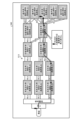
- FIG. 6 is a diagram (1) showing an example of a care pathway display.
- a screen 200 including a care pathway G10 in which the care paths of 100 patients who were transported by ambulance are combined is illustrated.
- the care pathway G10 it can be understood that Hospital A, Hospital B, and Hospital C are independently providing medical care for the highly acute and acute phases.
- Hospital B and Hospital C are collaborating with Hospital D in medical care from the acute phase to the early recovery phase.
- Hospital A is collaborating with Hospital D and Hospital E in medical care from the early recovery phase to the late recovery phase.
- Hospital E is collaborating with Hospital F
- Hospital D is collaborating with Hospitals F to I in medical care from the late recovery phase to the maintenance phase.
- FIG. 7 is a diagram (2) showing an example of a care pathway display.
- FIG. 7 also shows an example of a screen 210 including a care pathway G11 in which the care paths of 100 patients who were transported by ambulance are combined, as a display for policy planners.
- the care pathway G11 the number of patients passing through each edge included in the care pathway G11 is plotted, compared to the care pathway G10 shown in FIG. 6.
- each edge included in the care pathway G11 is displayed with a thickness corresponding to the number of patients passing through the edge, compared to the care pathway G10 shown in FIG. 6.
- the resources at each node included in the care pathway G11 for example, the number of doctors, are plotted.
- the display unit 15D can also display the index values of the evaluation items calculated by the calculation unit 15C in association with the medical institutions included in the care pathway generated by the generation unit 15B. At this time, the display unit 15D can display the index values of the evaluation items in association with all medical institutions included in the care pathway, but can also narrow down the index values to evaluation items whose index values satisfy certain conditions and display the associated index values of the evaluation items.
- FIG. 8 is a diagram (3) showing an example of a care pathway display.
- FIG. 8 also shows an example of a screen 220 including a care pathway G12 in which care paths for 100 patients who were transported by ambulance are combined, as a display for policy planners.
- the care pathway G12 is different from the care pathway G11 shown in FIG. 7 in that medical institutions that satisfy condition 1, that is, the number of patients whose length of stay exceeds the first threshold Th1 is equal to or greater than the second threshold Th2, are highlighted.
- the first threshold Th1 to be compared with the length of stay can be set based on, for example, statistics such as the average, median, and standard deviation of the length of stay of patients who receive medical services for the same disease at the same medical institution.
- an alert 221 is associated with the node "Hospital C for Advanced Acute Care" and displayed. By displaying such an alert 221, the occurrence of stagnation (prolonged hospitalization) can be visualized.
- FIG. 9 is a diagram showing an example of a length of stay graph.
- the vertical axis of the graph shown in FIG. 9 corresponds to patient ID, and the horizontal axis of the graph corresponds to the number of days of hospitalization (days).
- plots of the number of days of hospitalization of patients receiving medical services at Hospital C providing advanced acute care and whose length of hospitalization exceeds a first threshold are highlighted by being filled in black.
- the care pathway G12 shown in FIG. 8 differs from the care pathway G11 shown in FIG. 7 in that medical institutions that satisfy condition 2, that is, that the bed occupancy rate exceeds the third threshold value Th3, are highlighted.
- an alert 222 is associated with the node "Hospital E for late-stage convalescent care” and displayed.
- a bed occupancy rate graph (see FIG. 10) for the node "Hospital E for late-stage convalescent care” can be displayed.
- FIG. 10 is a diagram showing an example of a bed occupancy rate graph.
- the vertical axis of the graph shown in FIG. 10 corresponds to the bed occupancy rate, and the horizontal axis of the graph corresponds to the date.
- the bed occupancy rate graph displays the trend of the bed occupancy rate calculated by the calculation unit 15C for each interval, for example, for each "day", that is, the time series data. By displaying such a bed occupancy rate graph, it is possible to know the time when the bed occupancy rate at the node "Hospital E for late-stage convalescent care" reaches the third threshold value Th3.
- the display unit 15D can superimpose and display a care path related to a specific user on the care pathway generated by the generation unit 15B.
- the display unit 15D can accept the designation of a specific user via a care path selection screen exemplified in Figures 11 and 12.
- the care path selection screens shown in Figures 11 and 12 can be displayed either after the care pathway is displayed or when a request to display the care pathway is received.
- FIG. 11 and 12 are diagrams showing an example of a care path selection screen.
- the care path selection screen 230 shows a pull-down menu as an example of a GUI (Graphical User Interface) for specifying a medical institution in charge of medical care for each medical function.
- GUI Graphic User Interface
- FIG. 11 an example of selecting care paths for highly acute phase "Hospital C”, acute phase “Hospital C”, early convalescent phase “Hospital D”, late convalescent phase “Hospital D” and maintenance phase "Hospital G” is shown.
- a patient list L1 is displayed in which patients corresponding to the care paths shown in FIG. 11 are listed.
- a care path for a specific user can be selected. For example, when a patient with a patient ID "AAA" is selected from among the patients included in the patient list L1, a screen 240 including a care pathway G13 shown in FIG. 13 is displayed.
- FIG. 13 is a diagram (4) showing an example of a care pathway display.
- FIG. 13 also shows an example of a screen 240 including a care pathway G13 in which the care paths of 100 patients who were transported by ambulance are combined, as a display for policy planners.
- the care pathway G13 of patient ID "AAA" for example, the thick solid arrow in the figure, is superimposed.
- the statistical index values of each evaluation item of the entire policy flow can be displayed in association with the index values of each evaluation item of a specific user, for example, patient ID "AAA.”
- FIG. 14 is a diagram showing an example of a radar chart.
- a radar chart on which the statistical index values of five evaluation items of the entire policy flow (care pathway G13) are plotted, and a radar chart on which the statistical index values of five evaluation items of patient ID "AAA" are plotted are shown.
- the statistical index values of each evaluation item of the entire policy flow can be obtained by calculating the statistical value, for example the average value, of the index value of the entire care path of I name, 100 individual patients in this example, for each evaluation item.
- a draft of a policy that keeps the care path in the medical reorganization can be created. Also, if the care path of a specific user is inferior to the entire policy flow, a draft of a policy that removes the care path in the medical reorganization can be created.
- the display unit 15D can also superimpose and display a specified care path from among the care pathways generated by the generation unit 15B.
- the display unit 15D can superimpose and display a care path selected via the care path selection screen 230 shown in FIG. 11 on the care pathway generated by the generation unit 15B.
- FIG. 15 is a diagram (5) showing an example of a care pathway display.
- FIG. 13 also shows an example of a screen 250 including a care pathway G14 in which the care paths of 100 patients who were transported by ambulance are combined, as a display for policy planners.
- the care pathway G14 is similar in that a specified care path, for example, a thick solid arrow in the figure is superimposed and displayed.
- the care paths of the node "Hospital C for Advanced Acute Care”, the node “Hospital C for Acute Care”, the node “Hospital D for Early Convalescent Care”, the node “Hospital D for Early Convalescent Care”, and the node “Hospital G for Maintenance Care” are displayed.
- the care pathway G14 is different in that instead of the care path of the patient ID "AAA", the care path of the group X of x patients belonging to the care path is superimposed and displayed.
- the care path for group X of x patients is associated with and displayed the average length of hospital stay for the entire care path for group X (N days), the average medical costs for the entire care path (M), and the average re-admission rate (none).
- care pathway G14 shown in FIG. 15 can display the statistical index values of each evaluation item for the entire policy flow (care pathway G14) in association with the statistical index values of each evaluation item for the user group of group X.
- a radar chart on which the statistical index values of the five evaluation items of the entire policy flow (care pathway G14) are plotted, and a radar chart on which the statistical index values of the five evaluation items of the user group of group X are plotted can be displayed.
- the statistical index values of each evaluation item of the entire policy flow can be obtained by calculating the statistical value of the index value of the entire care path of I name, 100 individual patients in this example, for each evaluation item, for example, the average value.
- the statistical index value of each evaluation item of the user group of group X can be obtained by calculating the statistical value of the index value of the user group of group X belonging to the care paths of the nodes "Hospital C for Advanced Acute Care”, “Hospital C for Acute Care”, “Hospital D for Early Convalescent Care”, “Hospital D for Early Convalescent Care”, and “Hospital G for Maintenance Care”, for example, for each evaluation item.
- the radar chart of the entire policy flow and the radar chart of group X belonging to a specific care path it can be considered whether it is better to increase the number of members in group X.
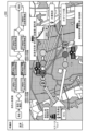
- the display unit 15D can display a specific policy flow among the policy flows included in the policy DB 13B in association with a care pathway generated from a data range corresponding to the specific policy flow. At this time, the display unit 15D can display nodes corresponding to the same type of medical function between the policy flow and the care pathway in a common display format, for example, a common color or common hatching. Furthermore, the display unit 15D can display nodes of medical institutions included in the care pathway in association with the location of the medical institution on a map.
- Figure 16 is a diagram (6) showing an example of the display of a care pathway.
- a screen 260 is displayed that includes the policy flow before medical reorganization and a care pathway generated in the data range corresponding to before medical reorganization.
- a care pathway for patients with acute myocardial infarction is displayed as an example of a disease.
- a care pathway in which Hospital A and Hospital B are specified is displayed as an example of a data range.
- the nodes "Hospital A for advanced acute care” and “Hospital B for advanced acute care” are displayed with a common hatching, i.e., hatching with light dots in the figure.
- the nodes "Hospital A for acute care” and “Hospital B for acute care” are displayed with a common hatching, i.e., hatching with dark dots in the figure.
- the nodes "Hospital A for convalescent care” and “Hospital B for convalescent care” are displayed with a common hatching, i.e., hatching with diagonal lines sloping upward to the right in the figure.
- the node "Hospital B for chronic care” is displayed with a common hatching, i.e., hatching with vertical lines in the figure.
- the nodes "Hospital A for Advanced Acute Care,” “Hospital A for Acute Care,” and “Hospital A for Convalescent Care” are placed in association with the icon of the location of Hospital A on the map.
- the nodes "Hospital B for Advanced Acute Care,” “Hospital B for Acute Care,” “Hospital B for Convalescent Care,” and “Hospital B for Chronic Care” are placed in association with the icon of the location of Hospital B on the map.
- the care pathway shown in Figure 16 displays the care path of a specific user, "Mr. A,” superimposed on the care pathway, and displays a graph of the number of days of hospitalization associated with the edge where congestion is occurring.
- the care pathway shown in Figure 16 can display the statistical index values of each evaluation item for the entire policy flow in association with the index values of each evaluation item for specific hospitals, for example "Hospital A” and "Hospital B.”
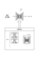
- FIG. 17 is a diagram showing an example of a radar chart.
- FIG. 17 shows a radar chart on which the statistical index values of five evaluation items of the entire policy flow before medical reorganization are plotted, a radar chart on which the statistical index values of five evaluation items of Hospital A are plotted, and a radar chart on which the statistical index values of five evaluation items of Hospital B are plotted.
- a radar chart on which the statistical index values of the five evaluation items are plotted for each medical function of the "acute phase" and "recovery phase" may be displayed.
- the statistical index values of each evaluation item can be compared between the same medical functions of Hospital A and Hospital B, and the results can be used as a basis for deciding whether to retain the medical function of the hospital with a better evaluation in the evaluation item that the policy planner considers important in the medical reorganization, or to eliminate the medical function of the hospital with a worse evaluation in the evaluation item that the policy planner considers important in the medical reorganization.
- Figure 18 is a diagram (7) showing an example of a care pathway display.
- a screen 270 is displayed that includes a policy flow after medical reorganization and a care pathway generated in a data range corresponding to the post-medical reorganization.
- a care pathway for an acute myocardial infarction patient is displayed as an example of a disease.
- a care pathway in which Hospital A and Hospital B are specified is displayed as an example of a data range.
- the policy flow after medical reorganization shown in Figure 18 differs from the policy flow before medical reorganization shown in Figure 16 in that the nodes "Hospital B for Advanced Acute Care” and “Hospital B for Acute Care” have been abolished, and the node "Hospital A for Convalescent Care” has also been abolished.
- the node "Hospital A providing advanced acute care” is displayed with common hatching, i.e., hatching with light dots in the figure. Furthermore, between the policy flows and care pathways after medical reorganization, the node "Hospital A providing acute care” is displayed with common hatching, i.e., hatching with dark dots in the figure. Furthermore, between the policy flows and care pathways after medical reorganization, the node "Hospital B providing recovery care” is displayed with common hatching, i.e., hatching with diagonal lines sloping upward to the right in the figure. Furthermore, between the policy flows and care pathways after medical reorganization, the node "Hospital B providing chronic care” is displayed with common hatching, i.e., hatching with vertical lines in the figure.
- the node "Hospital A for Advanced Acute Care” and the node “Hospital A for Acute Care” are placed in association with an icon showing the location of Hospital A on the map. Furthermore, in the care pathway shown in FIG. 18, the node “Hospital B for Convalescent Care” and the node “Hospital B for Chronic Care” are placed in association with an icon showing the location of Hospital B on the map.
- the care pathway of a specific user "Mr. A" is displayed superimposed on the care pathway shown in FIG. 18.
- the care pathway shown in Figure 18 can display the statistical index values of each evaluation item of the entire policy flow before and after medical reorganization, in association with the index values of each evaluation item of specific hospitals, for example "Hospital A” and "Hospital B,” before and after medical reorganization.
- FIG. 19 is a diagram showing an example of a radar chart.
- FIG. 19 shows a radar chart on which the statistical index values of five evaluation items of the entire policy flow before and after medical reorganization are plotted, a radar chart on which the statistical index values of five evaluation items of Hospital A before and after medical reorganization are plotted, and a radar chart on which the statistical index values of five evaluation items of Hospital B before and after medical reorganization are plotted.
- Hospital A and Hospital B a radar chart on which the statistical index values of the five evaluation items before and after medical reorganization are plotted for the medical functions remaining after medical reorganization may be displayed.
- each evaluation item that is, the results of medical reorganization, such as an increase in the BI score difference in the entire policy flow and Hospital A and Hospital B, an increase in the bed occupancy rate within an acceptable range, and a decrease in the number of days of hospitalization after medical reorganization.
- the display unit 15D can also predict an individual's care path based on the individual's attributes or personal information, and display the predicted individual's care path superimposed on the care pathway.
- FIG. 20 is a schematic diagram showing an example of a care path prediction model.
- a machine learning model m1 is used to predict an individual's care path.
- the machine learning model m1 may be realized by a neural network, a support vector machine, gradient boosting, or the like.
- a dataset TR11 can be used, which includes training data associated with attribute information such as part of an individual's address, age, and gender, or personal information such as an individual's address, age, gender, medical checkup results, family doctor, and medical history, and the correct answer label of the care path.
- At least one of the individual's attribute information or personal information can be used as an explanatory variable of the machine learning model m1, and the label can be used as the objective variable of the machine learning model m1, and the machine learning model m1 can be trained according to any machine learning algorithm, such as deep learning. This results in a trained machine learning model M1.
- the machine learning model M1 In the prediction phase, at least one of an individual's attribute information or personal information is input to the machine learning model M1.
- the machine learning model M1 to which the individual's attribute information or personal information has been input in this manner outputs a care path for the individual. Furthermore, by generating a machine learning model M1 for each disease, it is possible to realize prediction of the care path for any disease.
- FIG. 20 shows examples of individual attribute information and personal information as input to the machine learning model M1
- other information such as part of a care path, such as an end point.
- the display unit 15D can predict an individual's index value based on the individual's attributes or personal information, and display the predicted individual's index value in association with a care pathway.
- FIG. 21 is a schematic diagram showing an example of an index value prediction model.
- a machine learning model m2 is used to predict an individual's index value.
- the machine learning model m2 may be realized by a neural network, a support vector machine, gradient boosting, or the like.
- a dataset TR12 can be used, which includes training data associated with attribute information such as part of an individual's address, age, and gender, or personal information such as an individual's address, age, gender, medical checkup results, family doctor, and medical history, as well as correct answer labels for index values of specific evaluation items.
- At least one of the individual's attribute information or personal information can be used as an explanatory variable of the machine learning model m2, and the label can be used as the objective variable of the machine learning model m2, and the machine learning model m2 can be trained according to any machine learning algorithm, such as deep learning. This results in a trained machine learning model M2.
- the machine learning model M2 In the prediction phase, at least one of the individual's attribute information or personal information is input to the machine learning model M2.
- the machine learning model M2 to which the individual's attribute information or personal information has been input in this manner outputs the individual's prediction index value. Furthermore, by generating the machine learning model M2 for each disease and each evaluation item, it is possible to realize prediction of the care path for any disease.
- Figure 22 is a diagram (8) showing an example of the display of a care pathway.
- Figure 18 displays, as an example only, a screen 280 including a policy flow before medical reorganization and a care pathway generated with a data range corresponding to before medical reorganization.
- Figure 18 displays a care pathway for patients with acute myocardial infarction as an example of a disease.
- Figure 16 displays a care pathway in which Hospital A and Hospital B are specified as an example of a data range.
- the care pathway shown in FIG. 22 differs from the care pathway shown in FIG. 16 in that the care pathway for the individual "Mr. B" predicted by the care path prediction model shown in FIG. 20 is displayed superimposed. Furthermore, the care pathway shown in FIG. 22 can display the statistical index values of each evaluation item for the entire policy flow in association with the predicted index values of each evaluation item for a specific individual "Mr. B.”
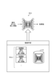
- Fig. 23 is a diagram showing an example of a radar chart.
- Fig. 23 shows a radar chart on which statistical index values of five evaluation items of the entire policy flow before medical reorganization are plotted, and a radar chart on which predicted index values of five evaluation items for an individual "Mr. B" are plotted.
- Mr. B predicted index values of five evaluation items for an individual "Mr. B" are plotted.
- Generation process Fig. 24 is a flowchart showing the procedure of the generation process. As shown in Fig. 24, when the reception unit 15A receives a care pathway display request (step S101), the generation unit 15B executes the following process. That is, the generation unit 15B extracts medical data corresponding to the data range specified in the display request from the medical data stored in the medical DB 13A (step S102).
- the generation unit 15B executes loop process 1, which repeats the processes from step S103 to step S109 described below a number of times corresponding to the number I of patients included in the medical data corresponding to the above data range.
- the generation unit 15B creates a list of medical institutions for the i-th patient when using medical services corresponding to each medical function, such as highly acute phase, acute phase, recovery phase, maintenance phase, etc. (step S103).
- the generation unit 15B then sorts the medical institutions included in the list of medical institutions for the i-th patient obtained by the listing in step S103 in chronological order (step S104).
- the generation unit 15B executes loop process 2, which repeats the processes from step S105 to step S109 described below a number of times corresponding to the number J of medical institutions included in the medical institution list for the i-th patient.
- the generation unit 15B determines whether a node corresponding to the jth medical institution among the J medical institutions included in the medical institution list of the ith patient has not yet been generated on the care pathway being generated (step S105).
- step S105 If a node corresponding to the jth medical institution has not been generated (step S105 Yes), the generation unit 15B adds a node corresponding to the jth medical institution to the care pathway being generated (step S106).
- the generation unit 15B determines whether an edge has not yet been generated between the node of the jth medical institution and the node of the j-1th medical institution in the care pathway being generated (step S107).
- the generation unit 15B adds an edge between the jth medical institution node and the j-1th medical institution node (step S108). Furthermore, the generation unit 15B increments the number of paths of the edge connecting the jth medical institution node and the j-1th medical institution node, i.e., the number of patients, by one (step S109).
- FIG. 25 is a flowchart showing the procedure of the calculation process.
- the calculation unit 15C executes a loop process 1 in which the process of step S301 and the process of step S302 are repeated for the number of times corresponding to the number K of evaluation items.
- the calculation unit 15C executes a loop process 2 in which the process of step S301 is repeated for the minimum unit corresponding to the kth evaluation item. That is, the calculation unit 15C calculates the index value of the mth minimum unit for the kth evaluation item (step S301). By repeating such loop process 2, the index values of M minimum units of the kth evaluation item are calculated.
- the calculation unit 15C calculates the index value of the entire care pathway of the kth evaluation item by calculating a statistical value, for example, an average value, of the index values of the M minimum units of the kth evaluation item (step S302). Then, by repeating the loop process 1, the index values of the M minimum units and the index value of the entire care pathway are calculated for each of the K evaluation items.
- the server device 10 according to the present embodiment generates and displays a pathway showing the route of medical institutions when multiple users use a medical service corresponding to each medical function. Therefore, the server device 10 according to the present embodiment can improve the visibility of the service route, for example, the linkage status of medical functions.
- the server device 10 displays a care pathway, which indicates the route through medical institutions when multiple users use medical services corresponding to each medical function, superimposed on the care path and index value of a specific individual. Therefore, the server device 10 according to this embodiment can verify the effectiveness of measures for a specific user.
- the server device 10 displays medical institutions that correspond to the same type of medical function between the policy flow and the care pathway in a common display format, and displays the medical institutions included in the care pathway in association with their location on a map. Therefore, the server device 10 according to this embodiment can improve the readability of the policy flow.
- each component of each device shown in the figure does not necessarily have to be physically configured as shown in the figure.
- the specific form of distribution and integration of each device is not limited to that shown in the figure, and all or part of them can be functionally or physically distributed and integrated in any unit depending on various loads, usage conditions, etc.
- the reception unit 15A, the generation unit 15B, the calculation unit 15C, or the display unit 15D may be connected via a network as an external device of the server device 10.
- the reception unit 15A, the generation unit 15B, the calculation unit 15C, or the display unit 15D may be included in a separate device, and the functions of the server device 10 may be realized by cooperating with each other through a network connection.
- FIG. 26 is a diagram showing an example of a hardware configuration.
- the computer 100 has an operation unit 110a, a speaker 110b, a camera 110c, a display 120, and a communication unit 130. Furthermore, the computer 100 has a CPU 150, a ROM 160, a HDD 170, and a RAM 180. Each of these units 110 to 180 is connected via a bus 140.
- HDD 170 stores a display program 170a that performs the same functions as reception unit 15A, generation unit 15B, calculation unit 15C, and display unit 15D shown in embodiment 1 above.
- This display program 170a may be integrated or separated, similar to the components of reception unit 15A, generation unit 15B, calculation unit 15C, and display unit 15D shown in FIG. 1.
- HDD 170 does not necessarily need to store all of the data shown in embodiment 1 above, as long as the data used for processing is stored in HDD 170.
- the CPU 150 reads out the display program 170a from the HDD 170 and loads it in the RAM 180.
- the display program 170a functions as a display process 180a, as shown in FIG. 26.
- This display process 180a loads various data read out from the HDD 170 in an area of the storage area of the RAM 180 that is allocated to the display process 180a, and executes various processes using the loaded data.
- examples of processes executed by the display process 180a include the processes shown in FIG. 24 and FIG. 25. Note that in the CPU 150, it is not necessary for all of the processing units shown in the above embodiment 1 to operate, and it is sufficient that the processing units corresponding to the processes to be executed are virtually realized.
- the display program 170a does not necessarily have to be stored in the HDD 170 or the ROM 160 from the beginning.
- each program may be stored on a "portable physical medium" such as a flexible disk, a so-called FD, a CD-ROM, a DVD disk, a magneto-optical disk, or an IC card that is inserted into the computer 100.
- the computer 100 may then retrieve and execute each program from this portable physical medium.
- each program may be stored on another computer or server device connected to the computer 100 via a public line, the Internet, a LAN, a WAN, or the like, and the computer 100 may retrieve and execute each program from this.
Landscapes
- Engineering & Computer Science (AREA)
- Health & Medical Sciences (AREA)
- Biomedical Technology (AREA)
- General Business, Economics & Management (AREA)
- Business, Economics & Management (AREA)
- Medical Informatics (AREA)
- Public Health (AREA)
- Primary Health Care (AREA)
- General Health & Medical Sciences (AREA)
- Epidemiology (AREA)
- General Engineering & Computer Science (AREA)
- Theoretical Computer Science (AREA)
- Human Computer Interaction (AREA)
- Physics & Mathematics (AREA)
- General Physics & Mathematics (AREA)
- Medical Treatment And Welfare Office Work (AREA)
Priority Applications (4)
| Application Number | Priority Date | Filing Date | Title |
|---|---|---|---|
| PCT/JP2023/013725 WO2024202069A1 (ja) | 2023-03-31 | 2023-03-31 | 表示方法、情報処理装置及び表示プログラム |
| EP23930703.6A EP4693314A4 (en) | 2023-03-31 | 2023-03-31 | Display method, information processing device, and display program |
| JP2025509646A JPWO2024202069A1 (https=) | 2023-03-31 | 2023-03-31 | |
| US19/337,258 US20260024654A1 (en) | 2023-03-31 | 2025-09-23 | Display method, information processing apparatus, and non-transitory computer-readable recording medium |
Applications Claiming Priority (1)
| Application Number | Priority Date | Filing Date | Title |
|---|---|---|---|
| PCT/JP2023/013725 WO2024202069A1 (ja) | 2023-03-31 | 2023-03-31 | 表示方法、情報処理装置及び表示プログラム |
Related Child Applications (1)
| Application Number | Title | Priority Date | Filing Date |
|---|---|---|---|
| US19/337,258 Continuation US20260024654A1 (en) | 2023-03-31 | 2025-09-23 | Display method, information processing apparatus, and non-transitory computer-readable recording medium |
Publications (1)
| Publication Number | Publication Date |
|---|---|
| WO2024202069A1 true WO2024202069A1 (ja) | 2024-10-03 |
Family
ID=92903760
Family Applications (1)
| Application Number | Title | Priority Date | Filing Date |
|---|---|---|---|
| PCT/JP2023/013725 Ceased WO2024202069A1 (ja) | 2023-03-31 | 2023-03-31 | 表示方法、情報処理装置及び表示プログラム |
Country Status (4)
| Country | Link |
|---|---|
| US (1) | US20260024654A1 (https=) |
| EP (1) | EP4693314A4 (https=) |
| JP (1) | JPWO2024202069A1 (https=) |
| WO (1) | WO2024202069A1 (https=) |
Citations (5)
| Publication number | Priority date | Publication date | Assignee | Title |
|---|---|---|---|---|
| JP2007004693A (ja) * | 2005-06-27 | 2007-01-11 | Toshiba Medical Systems Corp | 病院経営支援システム |
| JP2019046364A (ja) * | 2017-09-06 | 2019-03-22 | 株式会社Appdate | 医療機関検索装置、医療機関検索方法、医療機関検索装置用プログラム、および、表示制御装置 |
| JP2020204799A (ja) * | 2019-06-14 | 2020-12-24 | キヤノンメディカルシステムズ株式会社 | 治療選択支援装置 |
| JP2021039491A (ja) * | 2019-09-02 | 2021-03-11 | キヤノンメディカルシステムズ株式会社 | 診療支援装置 |
| JP2021089523A (ja) | 2019-12-03 | 2021-06-10 | 株式会社日立製作所 | 保健医療データ分析システム及び保健医療データ分析方法 |
-
2023
- 2023-03-31 JP JP2025509646A patent/JPWO2024202069A1/ja active Pending
- 2023-03-31 EP EP23930703.6A patent/EP4693314A4/en active Pending
- 2023-03-31 WO PCT/JP2023/013725 patent/WO2024202069A1/ja not_active Ceased
-
2025
- 2025-09-23 US US19/337,258 patent/US20260024654A1/en active Pending
Patent Citations (5)
| Publication number | Priority date | Publication date | Assignee | Title |
|---|---|---|---|---|
| JP2007004693A (ja) * | 2005-06-27 | 2007-01-11 | Toshiba Medical Systems Corp | 病院経営支援システム |
| JP2019046364A (ja) * | 2017-09-06 | 2019-03-22 | 株式会社Appdate | 医療機関検索装置、医療機関検索方法、医療機関検索装置用プログラム、および、表示制御装置 |
| JP2020204799A (ja) * | 2019-06-14 | 2020-12-24 | キヤノンメディカルシステムズ株式会社 | 治療選択支援装置 |
| JP2021039491A (ja) * | 2019-09-02 | 2021-03-11 | キヤノンメディカルシステムズ株式会社 | 診療支援装置 |
| JP2021089523A (ja) | 2019-12-03 | 2021-06-10 | 株式会社日立製作所 | 保健医療データ分析システム及び保健医療データ分析方法 |
Non-Patent Citations (1)
| Title |
|---|
| See also references of EP4693314A1 |
Also Published As
| Publication number | Publication date |
|---|---|
| JPWO2024202069A1 (https=) | 2024-10-03 |
| EP4693314A4 (en) | 2026-05-06 |
| US20260024654A1 (en) | 2026-01-22 |
| EP4693314A1 (en) | 2026-02-11 |
Similar Documents
| Publication | Publication Date | Title |
|---|---|---|
| Brailsford et al. | Emergency and on-demand health care: modelling a large complex system | |
| US8645158B2 (en) | Displaying clinical predicted length of stay of patients for workload balancing in a healthcare environment | |
| Andereck et al. | Seeking to reduce nonbeneficial treatment in the ICU: an exploratory trial of proactive ethics intervention | |
| Garvin et al. | Interorganizational care coordination of rural veterans by veterans affairs and community care programs: a systematic review | |
| Bastos et al. | Practices and challenges on coordinating the Brazilian Unified Health System | |
| JP7043235B2 (ja) | 病床管理業務支援システム | |
| Ibrahim et al. | Rapid development and utilization of a clinical intelligence dashboard for frontline clinicians to optimize critical resources during COVID-19 | |
| US20260106005A1 (en) | Universal medical charting | |
| Ismail et al. | Integrated decision support systems for improving emergency department performance in Irish hospitals | |
| Saxon et al. | Reducing geriatric outpatient waiting times: Impact of an advanced health practitioner | |
| Taghipour et al. | An integrated framework to evaluate and improve the performance of emergency departments during the COVID-19 pandemic: A mathematical programing approach | |
| Falconer et al. | Ed triage process improvement: timely vital signs for less acute patients | |
| Ozkaynak et al. | Characterizing patient care in hospital emergency departments | |
| Raghupathi | An empirical investigation of chronic diseases: a visualization approach to medicare in the United States | |
| Goh et al. | Economic evaluation of novel models of care for patients with acute medical problems | |
| Satre et al. | Implementation and operational research: Affordable Care Act implementation in a California health care system leads to growth in HIV-positive patient enrollment and changes in patient characteristics | |
| Hao et al. | Emergency care efficiency vs. quality: Uncovering hidden consequences of fast-track routing decisions | |
| JP2017126147A (ja) | 面談支援装置、面談支援プログラム、面談支援システム及び面談支援方法 | |
| JP2020106882A (ja) | 保険設計支援システム及び保険設計支援方法 | |
| WO2024202069A1 (ja) | 表示方法、情報処理装置及び表示プログラム | |
| WO2024202070A1 (ja) | 表示方法、情報処理装置及び表示プログラム | |
| WO2024202068A1 (ja) | 表示方法、情報処理装置及び表示プログラム | |
| Landa et al. | Modelling hospital medical wards to address patient complexity: a case-based simulation-optimization approach | |
| Kilinc et al. | A study of home telehealth diffusion among US home healthcare agencies using system dynamics | |
| Aharonson‐Daniel et al. | Time studies in A&E departments‐a useful tool for management |
Legal Events
| Date | Code | Title | Description |
|---|---|---|---|
| 121 | Ep: the epo has been informed by wipo that ep was designated in this application |
Ref document number: 23930703 Country of ref document: EP Kind code of ref document: A1 |
|
| ENP | Entry into the national phase |
Ref document number: 2025509646 Country of ref document: JP Kind code of ref document: A |
|
| WWE | Wipo information: entry into national phase |
Ref document number: 2025509646 Country of ref document: JP |
|
| WWE | Wipo information: entry into national phase |
Ref document number: 2023930703 Country of ref document: EP |
|
| NENP | Non-entry into the national phase |
Ref country code: DE |
|
| ENP | Entry into the national phase |
Ref document number: 2023930703 Country of ref document: EP Effective date: 20251031 |
|
| ENP | Entry into the national phase |
Ref document number: 2023930703 Country of ref document: EP Effective date: 20251031 |
|
| ENP | Entry into the national phase |
Ref document number: 2023930703 Country of ref document: EP Effective date: 20251031 |
|
| ENP | Entry into the national phase |
Ref document number: 2023930703 Country of ref document: EP Effective date: 20251031 |
|
| ENP | Entry into the national phase |
Ref document number: 2023930703 Country of ref document: EP Effective date: 20251031 |
|
| ENP | Entry into the national phase |
Ref document number: 2023930703 Country of ref document: EP Effective date: 20251031 |
|
| ENP | Entry into the national phase |
Ref document number: 2023930703 Country of ref document: EP Effective date: 20251031 |
|
| ENP | Entry into the national phase |
Ref document number: 2023930703 Country of ref document: EP Effective date: 20251031 |
|
| WWP | Wipo information: published in national office |
Ref document number: 2023930703 Country of ref document: EP |