WO2024202036A1 - リスク提示装置、リスク提示方法及びプログラム - Google Patents
リスク提示装置、リスク提示方法及びプログラム Download PDFInfo
- Publication number
- WO2024202036A1 WO2024202036A1 PCT/JP2023/013628 JP2023013628W WO2024202036A1 WO 2024202036 A1 WO2024202036 A1 WO 2024202036A1 JP 2023013628 W JP2023013628 W JP 2023013628W WO 2024202036 A1 WO2024202036 A1 WO 2024202036A1
- Authority
- WO
- WIPO (PCT)
- Prior art keywords
- risk
- vehicle
- individual sector
- objects
- sector
- Prior art date
- Legal status (The legal status is an assumption and is not a legal conclusion. Google has not performed a legal analysis and makes no representation as to the accuracy of the status listed.)
- Ceased
Links
Images



Classifications
-
- G—PHYSICS
- G06—COMPUTING OR CALCULATING; COUNTING
- G06V—IMAGE OR VIDEO RECOGNITION OR UNDERSTANDING
- G06V20/00—Scenes; Scene-specific elements
- G06V20/50—Context or environment of the image
- G06V20/56—Context or environment of the image exterior to a vehicle by using sensors mounted on the vehicle
- G06V20/58—Recognition of moving objects or obstacles, e.g. vehicles or pedestrians; Recognition of traffic objects, e.g. traffic signs, traffic lights or roads
-
- B—PERFORMING OPERATIONS; TRANSPORTING
- B60—VEHICLES IN GENERAL
- B60K—ARRANGEMENT OR MOUNTING OF PROPULSION UNITS OR OF TRANSMISSIONS IN VEHICLES; ARRANGEMENT OR MOUNTING OF PLURAL DIVERSE PRIME-MOVERS IN VEHICLES; AUXILIARY DRIVES FOR VEHICLES; INSTRUMENTATION OR DASHBOARDS FOR VEHICLES; ARRANGEMENTS IN CONNECTION WITH COOLING, AIR INTAKE, GAS EXHAUST OR FUEL SUPPLY OF PROPULSION UNITS IN VEHICLES
- B60K35/00—Instruments specially adapted for vehicles; Arrangement of instruments in or on vehicles
-
- B—PERFORMING OPERATIONS; TRANSPORTING
- B60—VEHICLES IN GENERAL
- B60K—ARRANGEMENT OR MOUNTING OF PROPULSION UNITS OR OF TRANSMISSIONS IN VEHICLES; ARRANGEMENT OR MOUNTING OF PLURAL DIVERSE PRIME-MOVERS IN VEHICLES; AUXILIARY DRIVES FOR VEHICLES; INSTRUMENTATION OR DASHBOARDS FOR VEHICLES; ARRANGEMENTS IN CONNECTION WITH COOLING, AIR INTAKE, GAS EXHAUST OR FUEL SUPPLY OF PROPULSION UNITS IN VEHICLES
- B60K35/00—Instruments specially adapted for vehicles; Arrangement of instruments in or on vehicles
- B60K35/20—Output arrangements, i.e. from vehicle to user, associated with vehicle functions or specially adapted therefor
- B60K35/21—Output arrangements, i.e. from vehicle to user, associated with vehicle functions or specially adapted therefor using visual output, e.g. blinking lights or matrix displays
- B60K35/22—Display screens
-
- B—PERFORMING OPERATIONS; TRANSPORTING
- B60—VEHICLES IN GENERAL
- B60K—ARRANGEMENT OR MOUNTING OF PROPULSION UNITS OR OF TRANSMISSIONS IN VEHICLES; ARRANGEMENT OR MOUNTING OF PLURAL DIVERSE PRIME-MOVERS IN VEHICLES; AUXILIARY DRIVES FOR VEHICLES; INSTRUMENTATION OR DASHBOARDS FOR VEHICLES; ARRANGEMENTS IN CONNECTION WITH COOLING, AIR INTAKE, GAS EXHAUST OR FUEL SUPPLY OF PROPULSION UNITS IN VEHICLES
- B60K35/00—Instruments specially adapted for vehicles; Arrangement of instruments in or on vehicles
- B60K35/20—Output arrangements, i.e. from vehicle to user, associated with vehicle functions or specially adapted therefor
- B60K35/28—Output arrangements, i.e. from vehicle to user, associated with vehicle functions or specially adapted therefor characterised by the type of the output information, e.g. video entertainment or vehicle dynamics information; characterised by the purpose of the output information, e.g. for attracting the attention of the driver
-
- B—PERFORMING OPERATIONS; TRANSPORTING
- B60—VEHICLES IN GENERAL
- B60R—VEHICLES, VEHICLE FITTINGS, OR VEHICLE PARTS, NOT OTHERWISE PROVIDED FOR
- B60R25/00—Fittings or systems for preventing or indicating unauthorised use or theft of vehicles
- B60R25/20—Means to switch the anti-theft system on or off
-
- B—PERFORMING OPERATIONS; TRANSPORTING
- B60—VEHICLES IN GENERAL
- B60W—CONJOINT CONTROL OF VEHICLE SUB-UNITS OF DIFFERENT TYPE OR DIFFERENT FUNCTION; CONTROL SYSTEMS SPECIALLY ADAPTED FOR HYBRID VEHICLES; ROAD VEHICLE DRIVE CONTROL SYSTEMS FOR PURPOSES NOT RELATED TO THE CONTROL OF A PARTICULAR SUB-UNIT
- B60W50/00—Details of control systems for road vehicle drive control not related to the control of a particular sub-unit, e.g. process diagnostic or vehicle driver interfaces
- B60W50/08—Interaction between the driver and the control system
- B60W50/14—Means for informing the driver, warning the driver or prompting a driver intervention
-
- G—PHYSICS
- G06—COMPUTING OR CALCULATING; COUNTING
- G06F—ELECTRIC DIGITAL DATA PROCESSING
- G06F3/00—Input arrangements for transferring data to be processed into a form capable of being handled by the computer; Output arrangements for transferring data from processing unit to output unit, e.g. interface arrangements
- G06F3/01—Input arrangements or combined input and output arrangements for interaction between user and computer
- G06F3/048—Interaction techniques based on graphical user interfaces [GUI]
- G06F3/0481—Interaction techniques based on graphical user interfaces [GUI] based on specific properties of the displayed interaction object or a metaphor-based environment, e.g. interaction with desktop elements like windows or icons, or assisted by a cursor's changing behaviour or appearance
- G06F3/04817—Interaction techniques based on graphical user interfaces [GUI] based on specific properties of the displayed interaction object or a metaphor-based environment, e.g. interaction with desktop elements like windows or icons, or assisted by a cursor's changing behaviour or appearance using icons
-
- G—PHYSICS
- G06—COMPUTING OR CALCULATING; COUNTING
- G06F—ELECTRIC DIGITAL DATA PROCESSING
- G06F3/00—Input arrangements for transferring data to be processed into a form capable of being handled by the computer; Output arrangements for transferring data from processing unit to output unit, e.g. interface arrangements
- G06F3/01—Input arrangements or combined input and output arrangements for interaction between user and computer
- G06F3/048—Interaction techniques based on graphical user interfaces [GUI]
- G06F3/0484—Interaction techniques based on graphical user interfaces [GUI] for the control of specific functions or operations, e.g. selecting or manipulating an object, an image or a displayed text element, setting a parameter value or selecting a range
- G06F3/04845—Interaction techniques based on graphical user interfaces [GUI] for the control of specific functions or operations, e.g. selecting or manipulating an object, an image or a displayed text element, setting a parameter value or selecting a range for image manipulation, e.g. dragging, rotation, expansion or change of colour
-
- G—PHYSICS
- G06—COMPUTING OR CALCULATING; COUNTING
- G06F—ELECTRIC DIGITAL DATA PROCESSING
- G06F3/00—Input arrangements for transferring data to be processed into a form capable of being handled by the computer; Output arrangements for transferring data from processing unit to output unit, e.g. interface arrangements
- G06F3/01—Input arrangements or combined input and output arrangements for interaction between user and computer
- G06F3/048—Interaction techniques based on graphical user interfaces [GUI]
- G06F3/0484—Interaction techniques based on graphical user interfaces [GUI] for the control of specific functions or operations, e.g. selecting or manipulating an object, an image or a displayed text element, setting a parameter value or selecting a range
- G06F3/04847—Interaction techniques to control parameter settings, e.g. interaction with sliders or dials
-
- G—PHYSICS
- G08—SIGNALLING
- G08G—TRAFFIC CONTROL SYSTEMS
- G08G1/00—Traffic control systems for road vehicles
- G08G1/16—Anti-collision systems
-
- B—PERFORMING OPERATIONS; TRANSPORTING
- B60—VEHICLES IN GENERAL
- B60K—ARRANGEMENT OR MOUNTING OF PROPULSION UNITS OR OF TRANSMISSIONS IN VEHICLES; ARRANGEMENT OR MOUNTING OF PLURAL DIVERSE PRIME-MOVERS IN VEHICLES; AUXILIARY DRIVES FOR VEHICLES; INSTRUMENTATION OR DASHBOARDS FOR VEHICLES; ARRANGEMENTS IN CONNECTION WITH COOLING, AIR INTAKE, GAS EXHAUST OR FUEL SUPPLY OF PROPULSION UNITS IN VEHICLES
- B60K2360/00—Indexing scheme associated with groups B60K35/00 or B60K37/00 relating to details of instruments or dashboards
- B60K2360/16—Type of output information
- B60K2360/179—Distances to obstacles or vehicles
-
- B—PERFORMING OPERATIONS; TRANSPORTING
- B60—VEHICLES IN GENERAL
- B60W—CONJOINT CONTROL OF VEHICLE SUB-UNITS OF DIFFERENT TYPE OR DIFFERENT FUNCTION; CONTROL SYSTEMS SPECIALLY ADAPTED FOR HYBRID VEHICLES; ROAD VEHICLE DRIVE CONTROL SYSTEMS FOR PURPOSES NOT RELATED TO THE CONTROL OF A PARTICULAR SUB-UNIT
- B60W50/00—Details of control systems for road vehicle drive control not related to the control of a particular sub-unit, e.g. process diagnostic or vehicle driver interfaces
- B60W50/08—Interaction between the driver and the control system
- B60W50/14—Means for informing the driver, warning the driver or prompting a driver intervention
- B60W2050/146—Display means
Definitions
- the present invention relates to a risk presentation device, a risk presentation method, and a program.
- Occupants of a vehicle recognize a risk object and then take action to deal with the risk object, if necessary. If vehicle occupants can easily recognize risk objects, safety from the risk objects is improved.
- a risk presentation device for presenting risk information to a vehicle occupant
- the risk presentation device comprising: an identification means for identifying risk objects present around the vehicle; and a presentation means for presenting to a user a risk information image including a plurality of sectors corresponding to a plurality of directions relative to the vehicle, the presentation means highlighting an individual sector among the plurality of sectors when a risk object exists in a direction corresponding to the individual sector, and including an icon representing the type of the risk object within the individual sector, and including only one icon for the plurality of risk objects within the individual sector when multiple risk objects of the same type exist in the direction corresponding to the individual sector.
- risk information can be presented in an easily recognizable manner.
- FIG. 1 is a block diagram illustrating an example configuration of a vehicle according to some embodiments.
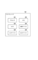
- FIG. 1 is a block diagram illustrating an example of a hardware configuration of a drive recorder according to some embodiments.
- FIG. 4 is a flow diagram illustrating an example of the operation of the drive recorder according to some embodiments. Schematic diagram illustrating an example of a risk display image according to some embodiments.
- FIG. 1 is a block diagram of a control device CNT and a schematic diagram of a vehicle V which is an application example of the control device CNT.
- the vehicle V is generally shown in plan view and side view.
- the vehicle V in this embodiment is a four-wheeled sedan-type passenger vehicle, and may be, for example, a parallel hybrid vehicle.
- the vehicle V is not limited to four-wheeled passenger vehicles, and may be a saddle-type vehicle (motorcycle, motor three-wheeler) or a large vehicle such as a truck or bus.
- the control device CNT includes a controller 1, which is an electronic circuit that controls the vehicle V, including driving assistance for the vehicle V.
- the controller 1 includes multiple ECUs (Electronic Control Units).
- An ECU is provided for each function of the control device CNT, for example.
- Each ECU includes a processor, such as a CPU (Central Processing Unit), a storage device such as a semiconductor memory, and an interface with an external device.
- the storage device stores programs executed by the processor and data used by the processor for processing.
- the interfaces include an input/output interface and a communication interface.
- Each ECU may include multiple processors, multiple storage devices, and multiple interfaces.
- the programs stored in the storage device may be stored in the storage device by being installed in the control device CNT using a storage medium such as a CD-ROM. Additionally or alternatively, the programs stored in the storage device may be downloaded from an external server via wireless communication.
- the controller 1 controls the drive (acceleration) of the vehicle V by controlling the power unit (power plant) 2.
- the power unit 2 is a driving unit that outputs driving force to rotate the drive wheels of the vehicle V, and can include an internal combustion engine, a motor, and an automatic transmission.
- the motor can be used as a driving source to accelerate the vehicle V, and can also be used as a generator during deceleration, etc. (regenerative braking).
- the controller 1 controls the output of the internal combustion engine and the motor and changes the gears of the automatic transmission in response to the driver's operation detected by the operation detection sensor 2a provided on the accelerator pedal AP and the operation detection sensor 2b provided on the brake pedal BP, and the vehicle speed of the vehicle V detected by the rotation speed sensor 2c.
- the automatic transmission is provided with a rotation speed sensor 2c that detects the rotation speed of the output shaft of the automatic transmission as a sensor that detects the driving state of the vehicle V.
- the vehicle speed of the vehicle V can be calculated from the detection result of the rotation speed sensor 2c.
- the controller 1 controls the braking (deceleration) of the vehicle V by controlling the hydraulic device 3.
- the driver's braking operation using the brake pedal BP is converted into hydraulic pressure in the brake master cylinder BM and transmitted to the hydraulic device 3.
- the hydraulic device 3 is an actuator that can control the hydraulic pressure of the hydraulic oil supplied to the brake devices 3a (e.g., disc brake devices) provided on each of the four wheels based on the hydraulic pressure transmitted from the brake master cylinder BM.
- the controller 1 can control the braking of the vehicle V by controlling the drive of the solenoid valves and the like provided in the hydraulic device 3.
- the controller 1 can also configure an electric servo brake system by controlling the distribution of the braking force provided by the brake device 3a and the braking force provided by the regenerative braking of the motor provided in the power unit 2.
- the controller 1 can also turn on the brake lamps 3b when braking.
- the controller 1 controls the steering of the vehicle V by controlling the electric power steering device 4.
- the electric power steering device 4 includes a mechanism for steering the front wheels in response to the driver's driving operation (steering operation) with respect to the steering wheel ST.
- the electric power steering device 4 includes a drive unit 4a that exerts a driving force (sometimes referred to as steering assist torque) for assisting the steering operation or automatically steering the front wheels of the vehicle V.
- the drive unit 4a includes a motor as a drive source.
- the electric power steering device 4 also includes a steering angle sensor 4b that detects the steering angle, a torque sensor 4c that detects the steering torque borne by the driver (called steering burden torque and distinguished from steering assist torque), and the like.
- the controller 1 controls the electric parking brake device 3c that is provided on the rear wheels of the vehicle V.
- the electric parking brake device 3c has a mechanism for locking the rear wheels.
- the controller 1 can control the locking and unlocking of the rear wheels by the electric parking brake device 3c.
- the controller 1 controls an information output device 5 that notifies the inside of the vehicle of information.
- the information output device 5 includes, for example, a display device 5a that notifies the driver of information by image and/or a voice output device 5b that notifies the driver of information by voice.
- the display device 5a includes, for example, a display device provided on the instrument panel or a display device provided on the steering wheel ST.
- the display device 5a may also include a head-up display.
- the information output device 5 may notify the occupants of information by vibration or light.
- the controller 1 accepts instruction inputs from an occupant (e.g., the driver) via the input device 6.
- the input device 6 is disposed in a position that can be operated by the driver, and includes, for example, a group of switches 6a through which the driver issues instructions to the vehicle V, and/or a turn signal lever 6b that activates a turn signal (blinker).
- the controller 1 recognizes and determines the current position and course (attitude) of the vehicle V.
- the vehicle V is provided with a gyro sensor 7a, a GNSS (Global Navigation Satellite System) sensor 7b, and a communication device 7c.
- the gyro sensor 7a detects the rotational motion (yaw rate) of the vehicle V.
- the GNSS sensor 7b detects the current position of the vehicle V.
- the communication device 7c wirelessly communicates with a server that provides map information and traffic information to obtain this information.
- the controller 1 determines the course of the vehicle V based on the detection results of the gyro sensor 7a and the GNSS sensor 7b, and sequentially obtains map information related to the course from the server via the communication device 7c and stores it in the database 7d (storage device).
- the vehicle V may be provided with other sensors for detecting the state of the vehicle V, such as an acceleration sensor that detects the acceleration of the vehicle V.
- the controller 1 performs driving assistance for the vehicle V based on the detection results of various detection units provided in the vehicle V.
- the vehicle V is provided with surrounding detection units 8a-8b, which are external sensors that detect the outside of the vehicle V (surrounding conditions), and interior detection units 9a-9b, which are interior sensors that detect the conditions inside the vehicle (the state of the occupants (particularly the driver)).
- the controller 1 is able to grasp the surrounding conditions of the vehicle V based on the detection results of the surrounding detection units 8a-8b, and perform driving assistance in accordance with the surrounding conditions. Furthermore, the controller 1 can determine, based on the detection results of the interior detection units 9a-9b, whether the driver is performing the specified operational obligations imposed on the driver when performing driving assistance.
- the surroundings detection unit 8a is an imaging device that captures images in front of the vehicle V (hereinafter, sometimes referred to as the forward camera 8a) and is attached, for example, to the inside of the passenger compartment of the windshield at the front of the roof of the vehicle V.
- the imaging device captures an image of a subject, generating an image of the subject.
- the controller 1 can extract the contours of objects and lane markings on the road (such as white lines) by analyzing the images generated by the forward camera 8a.
- the surrounding detection unit 8b is a millimeter wave radar (hereinafter sometimes referred to as radar 8b) that uses radio waves to detect targets around the vehicle V and detects (measures) the distance to the target and the direction (azimuth) of the target relative to the vehicle V.
- radar 8b a millimeter wave radar
- five radars 8b are provided: one in the center of the front of the vehicle V, one at each of the left and right corners of the front, and one at each of the left and right corners of the rear.
- the surrounding detection unit installed in the vehicle V is not limited to the above configuration, and the number of cameras and the number of radars may be changed, and a lidar (Light Detection and Ranging: LIDAR) that detects targets around the vehicle V may also be installed.
- LIDAR Light Detection and Ranging
- the in-vehicle detection unit 9a is an imaging device that captures images of the interior of the vehicle (hereinafter, sometimes referred to as in-vehicle camera 9a) and is attached, for example, to the inside of the vehicle compartment at the front of the roof of the vehicle interior V.
- the in-vehicle camera 9a is a driver monitor camera that captures images of the driver (for example, the driver's eyes and face).
- the controller 1 can determine the driver's line of sight and the direction of his or her face by analyzing the image (driver's facial image) generated by the in-vehicle camera 9a.
- the in-vehicle detection unit 9b is a grip sensor that detects the driver's grip of the steering wheel ST (hereinafter, sometimes referred to as grip sensor 9b), and is provided, for example, on at least a part of the steering wheel ST.
- grip sensor 9b a grip sensor that detects the driver's grip of the steering wheel ST
- a torque sensor 4c that detects the steering torque of the driver may be used.
- a drive recorder 100 is attached to the vehicle V.
- the drive recorder 100 records images of the surroundings of the vehicle V generated by the camera 203 (FIG. 2) of the drive recorder 100.
- the drive recorder 100 is attached, for example, to the inside of the passenger compartment of the front window at the front of the roof of the vehicle V.
- the attachment position of the drive recorder 100 (particularly, the position in the vehicle width direction) can vary depending on the type of vehicle V and the user's preferences.
- the drive recorder 100 identifies risk objects present in the surroundings of the vehicle V by analyzing images of the surroundings of the vehicle V, and presents a risk information image indicating the risk objects to an occupant of the vehicle (e.g., the driver). In the following description, an occupant of the vehicle V is simply referred to as an occupant.
- Driving assistance for the driver of the vehicle V includes, for example, acceleration/deceleration assistance, lane keeping assistance, and lane change assistance.
- Acceleration/deceleration assistance is a driving assistance (ACC: Adaptive Cruise Control) in which the controller 1 automatically controls the power unit 2 and hydraulic device 3 based on the detection results of the surroundings detection unit 8 and map information to automatically control the acceleration/deceleration of the vehicle V within a specified vehicle speed.
- ACC if there is a preceding vehicle, it is also possible to accelerate or decelerate the vehicle V so as to maintain a safe distance from the preceding vehicle.
- ACC reduces the operational burden on the driver of acceleration/deceleration operations (operation of the accelerator pedal AP and brake pedal BP).
- Lane keeping assist is a driving assist system (LKAS: Lane Keeping Assist System) in which the controller 1 automatically controls the electric power steering device 4 based on the detection results of the surrounding detection unit 8 and map information to keep the vehicle V inside the lane.
- LKAS reduces the driver's burden of steering (operation of the steering wheel ST) while the vehicle V is traveling straight.
- the lane change assist is a driving assist (ALC: Auto Lane Changing, ALCA: Active Lane Change Assist) in which the controller 1 automatically controls the power unit 2, hydraulic device 3, and electric power steering device 4 based on the detection results of the surrounding detection unit 8 and map information to change the driving lane of the vehicle V to an adjacent lane.
- ALC is lane change assist based on a system request
- ALCA is lane change assist based on an occupant request. Examples of system requests include a navigation system that guides the vehicle V to a destination and requests that the vehicle V change lanes, or a case where the vehicle needs to overtake a preceding vehicle regardless of whether route guidance is provided.
- ALC or ACLA reduces the driver's burden of accelerating, decelerating, and steering the vehicle V when changing lanes.
- driving assistance control may include, for example, a collision mitigation brake that assists in avoiding a collision with an object on the road (e.g., a pedestrian, another vehicle, or an obstacle) by controlling the hydraulic device 3, an ABS function, traction control, and/or attitude control of the vehicle V.
- a collision mitigation brake that assists in avoiding a collision with an object on the road (e.g., a pedestrian, another vehicle, or an obstacle) by controlling the hydraulic device 3, an ABS function, traction control, and/or attitude control of the vehicle V.
- the drive recorder 100 may include, for example, the components shown in FIG. 2.
- the drive recorder 100 may not include some of the components shown in FIG. 2, or may include components not included in FIG. 2.
- the drive recorder 100 may further include a Global Navigation Satellite System (GNSS) sensor and an accelerometer.
- GNSS Global Navigation Satellite System
- the processor 201 controls the overall operation of the drive recorder 100.
- the processor 201 may be configured, for example, as a central processing unit (CPU).
- the processor 201 may be a single processor or a collection of multiple processors.
- the memory 202 stores programs and data used in the operation of the drive recorder 100.
- the memory 202 may record images (particularly moving images) of the surroundings of the vehicle V generated by the camera 203.
- the memory 202 may be configured, for example, from a read-only memory (ROM) or a random access memory (RAM).
- the memory 202 may be a single memory or a collection of multiple memories.
- Camera 203 is a device for capturing images of the surroundings of vehicle V.
- An image of the surroundings of vehicle V is generated by camera 203 capturing images of the surroundings of vehicle V.
- Camera 203 may be a camera capable of capturing images of the surroundings of vehicle V at 360 degrees in a horizontal plane (a so-called 360-degree camera).
- camera 203 may be capable of capturing images of a specific range of the surroundings of vehicle V in a horizontal plane (for example, a 120-degree range in front of vehicle V centered in the vehicle length direction).
- Drive recorder 100 may further include a camera for capturing images of the rear of vehicle V.
- the communication device 204 is a device that communicates with a device different from the drive recorder 100.
- the communication device 204 may be capable of communicating with the communication device 7c of the vehicle V.
- the communication device 204 may be capable of communicating with a portable device (e.g., a smartphone) carried by the user.
- the communication by the communication device 204 may be wireless communication or wired communication.
- the communication by the communication device 204 may be short-range wireless communication such as Bluetooth (registered trademark).
- the input device 205 is a device for receiving instructions from a user of the drive recorder 100.
- the input device 205 may be configured with a physical button, a toggle switch, a touch panel, or any combination of these. Instructions from the user to the drive recorder 100 may be obtained from another device via the communication device 204 in addition to or instead of via the input device 205.
- the output device 206 is a device for outputting information to a user.
- the output device 206 may be a display device such as a liquid crystal display, an audio device such as a speaker, a lamp, an indicator, or any combination of these.
- the output of information to the user may be performed in another device through the communication device 204.
- FIG. 3 an example of the operation of the drive recorder 100 will be described.
- an operation performed by the drive recorder 100 to present risk information to the occupant will be described.
- the drive recorder 100 operating in this manner functions as a risk presentation device.
- Each step of the method of FIG. 3 may be performed by the processor 201 executing a program stored in the memory 202.
- some or all of the steps of the method of FIG. 3 may be performed by a dedicated integrated circuit such as an application specific integrated circuit (ASIC).
- ASIC application specific integrated circuit
- the method of FIG. 3 may be started in response to the drive recorder 100 being powered on, in response to a user's instruction to start presenting risk information, or in another manner.
- the method of FIG. 3 may be executed while the vehicle V is traveling by manual driving, or while the vehicle V is traveling by automatic driving.
- the processor 201 acquires an image of the surroundings of the vehicle V generated by the camera 203.
- the camera 203 repeatedly captures the surroundings of the vehicle V during execution of the method of FIG. 3.
- the processor 201 may store the image in front of the vehicle V in the memory 202 for recording.
- the processor 201 identifies risk objects present around the vehicle V by analyzing the image acquired in S301.
- the risk objects may be traffic participants including pedestrians and cyclists.
- the traffic participants identified as risk objects may include other vehicles such as two-wheeled vehicles and four-wheeled vehicles.
- the processor 201 may identify all traffic participants included in the image around the vehicle V as risk objects, or may identify traffic participants that satisfy a certain condition as risk objects among these traffic participants.
- the processor 201 may identify traffic participants that are located on or near the path of the vehicle V, or that are moving toward or near the path of the vehicle V, as risk objects. What kind of objects are to be risk objects may be set in advance by the manufacturer of the drive recorder 100 and stored as data in the memory 202. In addition, the user of the drive recorder 100 may be able to change this setting.
- the processor 201 may identify, for each of the identified risk objects, the direction of the risk object relative to the vehicle V and the type of the risk object.
- the type of the risk object may be identified as one of a number of predefined types (e.g., "pedestrian,” “bicyclist,” “two-wheeled vehicle,” “four-wheeled vehicle,” “other”).
- the processor 201 may identify, for each of the identified risk objects, the distance from the vehicle V to the risk object.
- the processor 201 generates an image (hereinafter, risk information image) showing the risk object identified in S302, and presents the risk information image to the user.
- the risk information image may be presented to the user in any manner.
- the processor 201 may display the risk information image on the output device 206 (e.g., a display).
- the processor 201 may transmit the risk information image to another device via the communication device 204, so that the risk information image is displayed on the display of the device.
- the processor 201 may transmit the risk information image to the vehicle V, so that the risk information image is displayed on the display device 5a of the vehicle V.
- the processor 201 may transmit the risk information image to a mobile device (e.g., a smartphone) of the occupant, so that the risk information image is displayed on the display of the mobile device.
- a mobile device e.g., a smartphone
- the processor 201 repeats the above steps S301 to S303 to update the risk information image to show the most recent risk target.
- the processor 201 may repeat the above steps S301 to S303 at a specific interval (e.g., every 10 ms, 100 ms, etc.).
- FIG. 4 shows risk objects identified by the processor 201 executing S301 and S302 at a certain time.
- four pedestrians 401-404 and one cyclist 405 are identified as risk objects.
- the surroundings of the vehicle V are divided into eight directions 400A-400H in the horizontal plane (eight equal parts in the example of FIG. 4).
- the direction 400A represents the front of the vehicle V.
- the direction 400B represents the right front of the vehicle V.
- the direction 400C represents the right side of the vehicle V.
- the direction 400D represents the right rear of the vehicle V.
- the direction 400E represents the rear of the vehicle V.
- the direction 400F represents the left rear of the vehicle V.
- the direction 400G represents the left side of the vehicle V.
- the direction 400H represents the left front of the vehicle V.
- pedestrians 401 and 402 are in direction 400H relative to the vehicle.
- Pedestrian 403 and bicyclist 405 are in direction 400A relative to the vehicle.
- Pedestrian 404 is on the boundary between directions 400B and 400C relative to the vehicle.
- the lower part of Figure 4 shows a risk information image 410 presented to the occupant.
- the risk information image 410 includes a number of sectors 411A-411H corresponding to a number of directions 400A-400H relative to the vehicle V.
- Each of the sectors 411A-411H is fan-shaped and has a central angle of 45 degrees.
- the centers of the sectors 411A-411H are aligned with each other, and the interiors of the sectors 411A-411H do not overlap with each other. Therefore, the sectors 411A-411H form a disk.
- Sector 411A is located above the center of the disk.
- Sector 411B is located above and to the right of the center of the disk.
- Sector 411C is located to the right of the center of the disk.
- Sector 411D is located below and to the right of the center of the disk.
- Sector 411E is located below and to the left of the center of the disk.
- Sector 411F is located below and to the left of the center of the disk.
- Sector 411G is located on the left side of the center of the disk.
- Sector 411H is located on the upper left side of the center of the disk.
- Each of the multiple sectors 411A to 411H corresponds to a direction with the same alphabet among the multiple directions 400A to 400H.
- sector 411A corresponds to direction 400A.
- the processor 201 When a risk object is present in a direction corresponding to an individual sector among the multiple sectors 411A to 411H, the processor 201 emphasizes the individual sector. For example, a pedestrian 403 and a bicyclist 405 are present in the direction 400A corresponding to sector 411A. Therefore, the processor 201 emphasizes sector 411A. In the example of FIG. 4, sector 411A is emphasized by thickening the outline of sector 411A. Alternatively, sector 411A may be emphasized in other ways. For example, sector 411A may be displayed in a color different from the background color for emphasis, or may be enlarged and displayed. Since pedestrians 401 and 402 are present in the direction 400H corresponding to sector 411H, the processor 201 also emphasizes sector 411H.
- the processor 201 may emphasize both of these two sectors. For example, a pedestrian 404 straddles two directions (directions 400B and 400C) that correspond to two adjacent sectors (sectors 411B and 411C). Therefore, the processor 201 may emphasize both sector 411B and sector 411C.
- the processor 201 when a risk object exists in a direction corresponding to an individual sector among the multiple sectors 411A-411H, the processor 201 includes an icon representing the type of risk object in this individual sector. For example, a pedestrian 403 and a bicyclist 405 are present in the direction 400A corresponding to sector 411A. Therefore, the processor 201 includes a pedestrian icon 414 representing a pedestrian and a bicycle icon 415 representing a bicyclist in sector 411A. In this way, when multiple different types of risk objects exist in the direction corresponding to an individual sector, the processor 201 includes an icon representing each type for each of the multiple types in the individual sector. This allows the occupant to easily recognize the direction in which the risk object exists and its type.
- the processor 201 may include only one icon for these multiple risk objects in the individual sector. For example, there are two pedestrians 401 and 402 in the direction 400H corresponding to sector 411H. Therefore, the processor 201 includes only one pedestrian icon 413 representing a pedestrian in sector 411H. This can improve the visibility of the icon compared to the case where multiple identical icons are displayed in one sector.
- the processor 201 may include an icon representing the type of risk object in only one of these two sectors.
- a pedestrian 404 spans two directions (directions 400B and 400C) corresponding to two adjacent sectors (sectors 411B and 411C). Therefore, the processor 201 includes a pedestrian icon 412 in only one of sectors 411B and 411C (sector 411B in the example of FIG. 4). This can prevent the passenger from mistaking that there are separate pedestrians in the direction 400B corresponding to sector 411B and the direction 400C corresponding to sector 411C. In addition, by not displaying an icon on the boundary between the two sectors, the visibility of the icon is improved.
- the processor 201 may include an icon in either of the two adjacent sectors. In the example of FIG. 4, if a pedestrian other than pedestrian 404 is present in direction 400C, processor 201 may include a pedestrian icon to represent this other pedestrian in sector 411C.
- processor 201 may or may not emphasize the icon representing the type of risk object with a higher risk than the icon representing the type of risk object with a lower risk. For example, in the example of FIG. 4, the risk related to pedestrian 403 is higher than the risk related to bicyclist 405. In this case, processor 201 may emphasize pedestrian icon 414 more than bicycle icon 415. For example, processor 201 may flash pedestrian icon 414 and light bicycle icon 415. Alternatively, processor 201 may display pedestrian icon 414 larger than bicycle icon 415. Processor 201 may determine the level of risk based on, for example, the distance between vehicle V and the risk object, the moving direction of the risk object, etc.
- the icon representing the type of risk object may be displayed at a fixed position within the sector.
- the icon representing the type of risk object may be displayed at a position within the sector that corresponds to the position of the risk object relative to the vehicle V.
- the distance of the icon from the center of a disk made up of multiple sectors 411A-411H may correspond to the distance of the risk object from the vehicle V.
- the direction of the icon relative to the center of a disk made up of multiple sectors 411A-411H may correspond to the direction of the risk object relative to the vehicle V. In this way, when the position of the icon corresponds to the position of the risk object, the processor 201 moves the icon within the individual sectors in accordance with the movement of the risk object that exists in the direction corresponding to the individual sector.
- the position of the icon may correspond to the position of the highest risk object among these multiple risk objects. For example, if pedestrian 401 is a higher risk than pedestrian 402, the position of the pedestrian icon 413 in sector 411H may correspond to the position of pedestrian 401 relative to vehicle V. Therefore, when multiple risk objects of the same type exist in a direction corresponding to an individual sector, the processor 201 moves the icon in the individual sector in accordance with the movement of the highest risk object among these multiple risk objects. This allows the occupant to recognize the movement of the risk object through the risk information image 410.
- the processor 201 identifies risk objects over 360 degrees around the vehicle V in the horizontal plane.
- the processor 201 may identify risk objects over a partial range around the vehicle V in the horizontal plane, depending on the shooting range of the camera 203.
- the processor 201 may identify risk objects in front of the vehicle V in the horizontal plane.
- the risk information image 410 may include, for example, sectors 411A, 411B, and 411H, and may not include sectors 411C to 411G.
- the drive recorder 100 executes the operation of FIG. 3.
- the control device CNT of the vehicle V may execute the operation of FIG. 3.
- the control device CNT functions as a risk presentation device.
- the control device CNT may use an image of the surroundings of the vehicle V captured by the surrounding detection unit 8a.
- the control device CNT may present a risk information image on the display device 5a of the vehicle V.
- This item allows risk information to be presented in an easily recognizable manner.
- [Item 2] 2. The risk presentation device according to claim 1, wherein the presentation means moves the icon within the individual sector in accordance with the movement of the risk object present in a direction corresponding to the individual sector. According to this item, a risk information image can be presented so that the movement of the risk object can be recognized.
- [Item 3] 3. The risk presentation device according to claim 2, wherein the presentation means moves the icon within the individual sector in accordance with the movement of a risk object with the highest risk among the multiple risk objects when multiple risk objects of the same type exist in a direction corresponding to the individual sector. According to this item, a risk information image can be presented so that the movement of high-risk risk objects can be recognized.
- the risk presentation device according to any one of items 1 to 3, wherein the presentation means includes an icon representing each type within the individual sector for each of the multiple types of risk objects when there are multiple different types of risk objects in the direction corresponding to the individual sector. This item allows risk information to be presented in a way that makes it easy to recognize the type of risk object.
- the presentation means emphasizes an icon representing a type of risk object having a higher risk than an icon representing a type of risk object having a lower risk between two different types of risk objects. This item allows risk information to be presented in a way that makes it easy to recognize the types of high-risk risk targets.
- a risk presentation method for presenting risk information to an occupant of a vehicle comprising: An identification step (S302) of identifying risk objects (401 to 405) existing around the vehicle; A presentation step (S303) of presenting to a user a risk information image (410) including a plurality of sectors (411A to 411H) corresponding to a plurality of directions (400A to 400H) relative to the vehicle, In the presenting step, When a risk object exists in a direction corresponding to an individual sector among the plurality of sectors, the individual sector is highlighted, and an icon (412 to 415) representing a type of the risk object is included in the individual sector; A risk presentation method, in which when multiple risk objects (401, 402) of the same type exist in a direction corresponding to the individual sector, only one icon (413) for the multiple risk objects is included within the individual sector. This item allows risk information to be presented in an easily recognizable manner.
Landscapes
- Engineering & Computer Science (AREA)
- Theoretical Computer Science (AREA)
- General Engineering & Computer Science (AREA)
- General Physics & Mathematics (AREA)
- Physics & Mathematics (AREA)
- Human Computer Interaction (AREA)
- Mechanical Engineering (AREA)
- Transportation (AREA)
- Automation & Control Theory (AREA)
- Chemical & Material Sciences (AREA)
- Combustion & Propulsion (AREA)
- Multimedia (AREA)
- Traffic Control Systems (AREA)
Priority Applications (4)
| Application Number | Priority Date | Filing Date | Title |
|---|---|---|---|
| CN202380095345.7A CN120858392A (zh) | 2023-03-31 | 2023-03-31 | 风险提示装置、风险提示方法以及程序 |
| JP2025509618A JPWO2024202036A1 (cg-RX-API-DMAC7.html) | 2023-03-31 | 2023-03-31 | |
| PCT/JP2023/013628 WO2024202036A1 (ja) | 2023-03-31 | 2023-03-31 | リスク提示装置、リスク提示方法及びプログラム |
| US19/341,043 US20260021824A1 (en) | 2023-03-31 | 2025-09-26 | Risk presentation apparatus and, risk presentation method |
Applications Claiming Priority (1)
| Application Number | Priority Date | Filing Date | Title |
|---|---|---|---|
| PCT/JP2023/013628 WO2024202036A1 (ja) | 2023-03-31 | 2023-03-31 | リスク提示装置、リスク提示方法及びプログラム |
Related Child Applications (1)
| Application Number | Title | Priority Date | Filing Date |
|---|---|---|---|
| US19/341,043 Continuation US20260021824A1 (en) | 2023-03-31 | 2025-09-26 | Risk presentation apparatus and, risk presentation method |
Publications (1)
| Publication Number | Publication Date |
|---|---|
| WO2024202036A1 true WO2024202036A1 (ja) | 2024-10-03 |
Family
ID=92904533
Family Applications (1)
| Application Number | Title | Priority Date | Filing Date |
|---|---|---|---|
| PCT/JP2023/013628 Ceased WO2024202036A1 (ja) | 2023-03-31 | 2023-03-31 | リスク提示装置、リスク提示方法及びプログラム |
Country Status (4)
| Country | Link |
|---|---|
| US (1) | US20260021824A1 (cg-RX-API-DMAC7.html) |
| JP (1) | JPWO2024202036A1 (cg-RX-API-DMAC7.html) |
| CN (1) | CN120858392A (cg-RX-API-DMAC7.html) |
| WO (1) | WO2024202036A1 (cg-RX-API-DMAC7.html) |
Cited By (1)
| Publication number | Priority date | Publication date | Assignee | Title |
|---|---|---|---|---|
| WO2026126532A1 (ja) * | 2024-12-13 | 2026-06-18 | パイオニア株式会社 | 表示制御装置、表示制御方法、及びプログラム |
Citations (5)
| Publication number | Priority date | Publication date | Assignee | Title |
|---|---|---|---|---|
| JP2010079561A (ja) * | 2008-09-25 | 2010-04-08 | Nissan Motor Co Ltd | 警告装置及び警告方法 |
| WO2013065348A1 (ja) * | 2011-10-31 | 2013-05-10 | 本田技研工業株式会社 | 車両周辺監視装置 |
| US20150314783A1 (en) * | 2014-04-30 | 2015-11-05 | Denso International America, Inc. | Situation Awareness Assistant For Vehicle Control |
| WO2019193819A1 (ja) * | 2018-04-02 | 2019-10-10 | 株式会社Jvcケンウッド | 車両用表示制御装置、車両用表示システム、車両用表示制御方法、およびプログラム |
| JP2019214348A (ja) * | 2018-06-14 | 2019-12-19 | クラリオン株式会社 | 物体認識装置 |
-
2023
- 2023-03-31 CN CN202380095345.7A patent/CN120858392A/zh active Pending
- 2023-03-31 WO PCT/JP2023/013628 patent/WO2024202036A1/ja not_active Ceased
- 2023-03-31 JP JP2025509618A patent/JPWO2024202036A1/ja active Pending
-
2025
- 2025-09-26 US US19/341,043 patent/US20260021824A1/en active Pending
Patent Citations (5)
| Publication number | Priority date | Publication date | Assignee | Title |
|---|---|---|---|---|
| JP2010079561A (ja) * | 2008-09-25 | 2010-04-08 | Nissan Motor Co Ltd | 警告装置及び警告方法 |
| WO2013065348A1 (ja) * | 2011-10-31 | 2013-05-10 | 本田技研工業株式会社 | 車両周辺監視装置 |
| US20150314783A1 (en) * | 2014-04-30 | 2015-11-05 | Denso International America, Inc. | Situation Awareness Assistant For Vehicle Control |
| WO2019193819A1 (ja) * | 2018-04-02 | 2019-10-10 | 株式会社Jvcケンウッド | 車両用表示制御装置、車両用表示システム、車両用表示制御方法、およびプログラム |
| JP2019214348A (ja) * | 2018-06-14 | 2019-12-19 | クラリオン株式会社 | 物体認識装置 |
Cited By (1)
| Publication number | Priority date | Publication date | Assignee | Title |
|---|---|---|---|---|
| WO2026126532A1 (ja) * | 2024-12-13 | 2026-06-18 | パイオニア株式会社 | 表示制御装置、表示制御方法、及びプログラム |
Also Published As
| Publication number | Publication date |
|---|---|
| US20260021824A1 (en) | 2026-01-22 |
| JPWO2024202036A1 (cg-RX-API-DMAC7.html) | 2024-10-03 |
| CN120858392A (zh) | 2025-10-28 |
Similar Documents
| Publication | Publication Date | Title |
|---|---|---|
| JP7411706B2 (ja) | 運転支援装置 | |
| US20200247415A1 (en) | Vehicle, and control apparatus and control method thereof | |
| US12202487B2 (en) | Driving support device, vehicle, driving support method, and storage medium | |
| US12371051B2 (en) | Vehicle, control device and control method therefor, and storage medium | |
| KR20240097726A (ko) | 차량용 표시 제어 장치, 차량용 표시 제어 방법, 및 비일시적 기억 매체 | |
| US20260021824A1 (en) | Risk presentation apparatus and, risk presentation method | |
| JP6982083B2 (ja) | 走行制御装置、および車両 | |
| JP2020152192A (ja) | 車両制御装置、車両制御方法、車両およびプログラム | |
| JP6595647B2 (ja) | 走行制御装置、車両および走行制御方法 | |
| JP2020199809A (ja) | 車両制御装置、車両、車両制御装置の動作方法およびプログラム | |
| CN110893881A (zh) | 车辆用控制系统及车辆的控制方法 | |
| JP2021154795A (ja) | 車両及びその制御装置 | |
| JP2021030836A (ja) | 車両並びにその制御装置及び制御方法 | |
| JP6953575B2 (ja) | 車両制御装置、車両、車両制御方法およびプログラム | |
| JP6932213B2 (ja) | 車両及びその制御装置 | |
| US12263841B2 (en) | Driving support device, vehicle, driving support method, and storage medium | |
| JP2014103433A (ja) | 車両用画像表示装置 | |
| WO2024202034A1 (ja) | ドライブレコーダ及びその制御方法 | |
| US12515660B2 (en) | Vehicle control device, operation method of vehicle control device, and storage medium | |
| US12570303B2 (en) | Control device and control method for vehicle, and storage medium | |
| US20250304092A1 (en) | Driving assistance device, vehicle, control method for driving assistance device, and storage medium | |
| JP7705426B2 (ja) | 車両の制御装置、制御方法、及びプログラム | |
| JP2020199811A (ja) | 車両制御装置、車両、車両制御装置の動作方法およびプログラム | |
| US20250371979A1 (en) | Driving assistance device, vehicle, control method for driving assistance device, and storage medium | |
| US20260038086A1 (en) | Image processing apparatus, control method of image processing apparatus, vehicle, and storage medium |
Legal Events
| Date | Code | Title | Description |
|---|---|---|---|
| 121 | Ep: the epo has been informed by wipo that ep was designated in this application |
Ref document number: 23930670 Country of ref document: EP Kind code of ref document: A1 |
|
| WWE | Wipo information: entry into national phase |
Ref document number: 202380095345.7 Country of ref document: CN |
|
| ENP | Entry into the national phase |
Ref document number: 2025509618 Country of ref document: JP Kind code of ref document: A |
|
| WWE | Wipo information: entry into national phase |
Ref document number: 2025509618 Country of ref document: JP |
|
| WWP | Wipo information: published in national office |
Ref document number: 202380095345.7 Country of ref document: CN |
|
| NENP | Non-entry into the national phase |
Ref country code: DE |
|
| 122 | Ep: pct application non-entry in european phase |
Ref document number: 23930670 Country of ref document: EP Kind code of ref document: A1 |