WO2024201908A1 - プログラム編集支援装置 - Google Patents
プログラム編集支援装置 Download PDFInfo
- Publication number
- WO2024201908A1 WO2024201908A1 PCT/JP2023/013232 JP2023013232W WO2024201908A1 WO 2024201908 A1 WO2024201908 A1 WO 2024201908A1 JP 2023013232 W JP2023013232 W JP 2023013232W WO 2024201908 A1 WO2024201908 A1 WO 2024201908A1
- Authority
- WO
- WIPO (PCT)
- Prior art keywords
- tool
- program
- index angle
- support device
- range
- Prior art date
- Legal status (The legal status is an assumption and is not a legal conclusion. Google has not performed a legal analysis and makes no representation as to the accuracy of the status listed.)
- Ceased
Links
Images





Classifications
-
- G—PHYSICS
- G05—CONTROLLING; REGULATING
- G05B—CONTROL OR REGULATING SYSTEMS IN GENERAL; FUNCTIONAL ELEMENTS OF SUCH SYSTEMS; MONITORING OR TESTING ARRANGEMENTS FOR SUCH SYSTEMS OR ELEMENTS
- G05B19/00—Program-control systems
- G05B19/02—Program-control systems electric
- G05B19/18—Numerical control [NC], i.e. automatically operating machines, in particular machine tools, e.g. in a manufacturing environment, so as to execute positioning, movement or co-ordinated operations by means of program data in numerical form
- G05B19/4093—Numerical control [NC], i.e. automatically operating machines, in particular machine tools, e.g. in a manufacturing environment, so as to execute positioning, movement or co-ordinated operations by means of program data in numerical form characterised by part programming, e.g. entry of geometrical information as taken from a technical drawing, combining this with machining and material information to obtain control information, named part program, for the NC machine
-
- G—PHYSICS
- G05—CONTROLLING; REGULATING
- G05B—CONTROL OR REGULATING SYSTEMS IN GENERAL; FUNCTIONAL ELEMENTS OF SUCH SYSTEMS; MONITORING OR TESTING ARRANGEMENTS FOR SUCH SYSTEMS OR ELEMENTS
- G05B19/00—Program-control systems
- G05B19/02—Program-control systems electric
- G05B19/18—Numerical control [NC], i.e. automatically operating machines, in particular machine tools, e.g. in a manufacturing environment, so as to execute positioning, movement or co-ordinated operations by means of program data in numerical form
- G05B19/406—Numerical control [NC], i.e. automatically operating machines, in particular machine tools, e.g. in a manufacturing environment, so as to execute positioning, movement or co-ordinated operations by means of program data in numerical form characterised by monitoring or safety
- G05B19/4068—Verifying part program on screen, by drawing or other means
-
- G—PHYSICS
- G05—CONTROLLING; REGULATING
- G05B—CONTROL OR REGULATING SYSTEMS IN GENERAL; FUNCTIONAL ELEMENTS OF SUCH SYSTEMS; MONITORING OR TESTING ARRANGEMENTS FOR SUCH SYSTEMS OR ELEMENTS
- G05B2219/00—Program-control systems
- G05B2219/30—Nc systems
- G05B2219/36—Nc in input of data, input key till input tape
- G05B2219/36041—Edit program step by step
-
- G—PHYSICS
- G05—CONTROLLING; REGULATING
- G05B—CONTROL OR REGULATING SYSTEMS IN GENERAL; FUNCTIONAL ELEMENTS OF SUCH SYSTEMS; MONITORING OR TESTING ARRANGEMENTS FOR SUCH SYSTEMS OR ELEMENTS
- G05B2219/00—Program-control systems
- G05B2219/30—Nc systems
- G05B2219/36—Nc in input of data, input key till input tape
- G05B2219/36204—Lathe, turning
-
- G—PHYSICS
- G05—CONTROLLING; REGULATING
- G05B—CONTROL OR REGULATING SYSTEMS IN GENERAL; FUNCTIONAL ELEMENTS OF SUCH SYSTEMS; MONITORING OR TESTING ARRANGEMENTS FOR SUCH SYSTEMS OR ELEMENTS
- G05B2219/00—Program-control systems
- G05B2219/30—Nc systems
- G05B2219/49—Nc machine tool, till multiple
- G05B2219/49157—Limitation, collision, interference, forbidden zones, avoid obstacles
Definitions
- This disclosure relates to a program editing support device.
- a machining method has been known in which turning is performed while dynamically changing the index angle of the tool as seen from the workpiece, in order to enable machining of complex shapes with a single turning tool.
- the cutting edge position and index angle are commanded for each block of the program, and linear and rotary axes are controlled based on these commands and a preset tool offset.
- Patent Documents 1 to 4 describe techniques related to machining using this type of index angle.
- This disclosure has been made in consideration of the above problems, and aims to provide a technology that can improve the degree of freedom in setting index angles within a range that avoids interference when creating a program that controls the operation of a machine tool.
- the present disclosure relates to a program editing support device that supports the creation of a program for turning a workpiece using a tool
- the program editing support device including: an analysis unit that generates command data from the program, the command data including at least a predetermined position of a predetermined point on the path of movement of the tool and a relative index angle between the tool and the workpiece at the predetermined position; a tool shape acquisition unit that acquires shape information of one or more components that make up the tool; a range calculation unit that calculates an index angle range in which the workpiece and the tool do not interfere with each other at the predetermined position based on the command data and the shape information; and a presentation unit that outputs the index angle range.
- This disclosure provides a technology that can improve the degree of freedom in setting index angles within a range that avoids interference when creating a program that controls the operation of a machine tool.
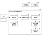
- FIG. 1 is a block diagram showing a configuration of a program editing support device according to a first embodiment.
- FIG. 11 is a diagram showing an example of a program command. 1 is a table showing tool behaviors specified by program commands.
- FIG. 2 is a diagram illustrating a schematic diagram of a relationship between a tool operation based on a program command and a workpiece.
- FIG. 2 is a diagram illustrating an example of a component of a tool.
- FIG. 10 is a diagram illustrating an example of shape information of a tool.
- FIG. 13 is a diagram illustrating a relationship between a program path and an index angle of a tool.
- FIG. 11 is a diagram showing an example of an index angle range presented to an operator in the first embodiment.
- FIG. 11 is a diagram showing an example of an index angle range presented to an operator in the first embodiment.
- FIG. 11 is a diagram showing an example of an index angle range changed by an operator in the first embodiment.
- 10 is a flowchart showing an example of the flow of a creation support process by the program editing support device of the present embodiment.
- FIG. 13 is a diagram showing an example of an index angle range and a recommended value presented to an operator in the second embodiment.
- FIG. 13 is a diagram showing an example of an index angle range changed by an operator in the second embodiment.
- FIG. 1 is a block diagram showing the configuration of a program editing support device 10 according to the first embodiment.
- the program editing support device 10 is an information processing device that supports the creation of a program for a machine tool that performs turning processing on a workpiece using a tool.
- the machine tool is, for example, a combined lathe having a mechanism for oscillating the tool.
- the program for the machine tool is, for example, an NC program for controlling the operation of the machine tool.
- the program sets command values for executing processing control such as the position of a specified point (location) on the tool's movement path, the method and amount of movement of the tool, and the relative index angle between the tool and the workpiece. Some of the command values may be parameters that are preset in the machine tool.
- the machine tool performs turning processing on the workpiece based on the program's command values and parameters that are preset in the machine tool.
- the program editing support device 10 is configured using a computer equipped with memories such as a ROM (read only memory) and a RAM (random access memory), a CPU (control processing unit), and a communication control unit, which are connected to each other via a bus.
- the program editing support device 10 may be a numerical control device that performs machining control, or may be a computer for creating programs independent of machine tools.
- a display device 50 and an input device 51 are connected to the program editing support device 10 of this embodiment.
- the display device 50 is a display that presents various information to the operator by image, sound, or both.
- the input device 51 is an interface that allows the operator to input various settings related to processing and machine tools by operating it.
- the display device 50 and the input device 51 may be configured independently, or the display device 50 and the input device 51 may be configured as an integrated touch panel display. In this way, the configurations of the display device 50 and the input device 51 are not particularly limited.
- the program editing support device 10 includes, as functional units operated by the above-mentioned CPU, an analysis unit 11, a tool shape acquisition unit 12, a range calculation unit 13, a presentation unit 14, a selection result acquisition unit 15, and a program correction unit 16.
- the functions and operations of each functional unit of the program editing support device 10 are achieved by the cooperation of the above-mentioned CPU, memory, and the control program stored in the memory. Each functional unit will be described below.
- the analysis unit 11 analyzes the program and obtains operation information for determining the operation of the tool.
- the operation information includes, for example, information for identifying the movement path of the tool tip position.
- the movement path corresponds to the shape of the workpiece.
- the movement path is described in the program command by dividing it into multiple blocks. For each block, position information such as the start point indicating the initial position of the tool and the end point indicating the end position, as well as the type of movement, are set.
- the analysis unit 11 of this embodiment acquires from the program operation information including a predetermined position point of each block on the movement path and the relative index angle between the tool and work at the predetermined position point.
- the predetermined position point of each block is, for example, the start point, end point, or an interpolation point indicating the position of the tool between the start point and end point of the above-mentioned block.
- the analysis unit 11 generates command data including a predetermined position point of each block on the movement path and the relative index angle between the tool and work at the predetermined position point based on the operation information.
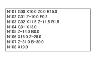
- Figure 2 is a diagram showing an example of a program command.
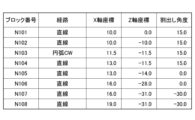
- Figure 3 is a table showing the behavior of the tool specified by the program command.
- Figure 4 is a diagram showing a schematic diagram of the relationship between the operation of the tool 20 based on the program command and the workpiece W.
- the tool 20 is configured to be rotatable by the B axis in the ZX plane.
- the workpiece W is the object of lathe machining that rotates around the Z axis as the axis of rotation.
- N101 to N108 shown in Figures 2 to 4 indicate each block in the program command.
- Blocks starting with “G00” or “G01” specify linear behavior and coordinates such as positioning and linear interpolation.
- Blocks starting with “G02” specify curved behavior and coordinates such as clockwise circular interpolation (arc CW).
- "X” in each block specifies the X coordinate
- "Z” specifies the Z coordinate
- "F” specifies the feed rate.
- the tip position of the cutting edge of tool 20 is determined by the X coordinate and Z coordinate.
- “R” specifies the radius in circular interpolation.
- “B” is the index angle specified in the program command.
- the tool 20 moves at an index angle of 15° at N101 to N104, at an index angle of 0° at N105 and N106, and at an index angle of -30° at N107 and N108.
- the analysis unit 11 generates command data from the program in Fig. 2 that indicates the position of the cutting edge tip of the tool 20 and the behavior of the index angle, etc., as shown in Figs. 3 and 4.
- the tool shape acquisition unit 12 acquires shape information relating to the shapes of the components that make up the tool on the plane where turning is performed.
- the components are, for example, a tool rest, a holder, a shank, a cutting edge, etc.
- the tool shape acquisition unit 12 may acquire the shape information from command values of the program, or may acquire the shape information from a memory unit (not shown) external to the program editing support device 10.
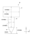
- Figure 5 is a diagram showing a schematic example of a component of a tool.
- Figure 5 shows multiple components 21-23 of a tool 20.
- the shape information is, for example, information indicating the shapes of the components 21-23 on the ZX plane where cutting is performed.
- Component 21 is the holder (or tool rest) part of tool 20.
- Component 22 is the shank part of tool 20.
- Component 23 is the cutting edge part of tool 20.
- tool shape acquisition unit 12 acquires the lengths in the X-axis direction and the Z-axis direction of each of component 21 and component 22, and acquires the length in the X-axis direction and the cutting edge angle of component 23.
- FIG. 6 is a diagram showing an example of the shape information of the tool 20.
- the tool shape acquisition unit 12 obtains vectors tracing the left and right end points of each element from the tip of the cutting edge based on information on the length in the X-axis direction, length in the Z-axis direction, and cutting edge angle of the components 21 to 23.
- the shape information of the component 23 is the left vector V1 of the cutting edge and the right vector V2 of the cutting edge.
- the left vector V1 of the cutting edge is composed of a Z-direction component V1z and an X-direction component V1x
- the right vector V2 of the cutting edge is composed of a Z-direction component V2z and an X-direction component V2x
- the shape information of the component 22 is the left vector V3 of the shank and the right vector V4 of the shank.
- the left vector V3 of the shank is composed of a Z-direction component V3z and an X-direction component V3x
- the right vector V4 of the shank is composed of a Z-direction component V4z and an X-direction component V4x
- the shape information of the component 21 includes the first left vector V5 of the holder, the first right vector V6 of the holder, the second left vector V7 of the holder, and the second right vector V8 of the holder. These also consist of Z-direction and X-direction components.
- the first left vector V5 consists of components V5z and V5x
- the first right vector V6 consists of components V6z and V6x
- the second left vector V7 consists of components V7z and V7x
- the second right vector V8 consists of components V8z and V8x .
- the index angle B is an angle that indicates the inclination of the tool 20, with 0 degrees (reference angle) being the state in which the imaginary straight line direction from the tip side (blade tip side) of the tool 20 toward the base end side coincides with the direction perpendicular to the Z-axis direction.
- the direction in which positive or negative is set is arbitrary. In this example, it is set so that tilting from the upright state to the left on the paper surface is a positive area. Tilting from the upright state to the right on the paper surface is a negative area.
- the range calculation unit 13 acquires the index angle of the tool 20 when the tool 20 interferes with the workpiece W based on the analysis results of the analysis unit 11 and the shape information acquired by the tool shape acquisition unit 12.
- the shape of the workpiece W can also be acquired using the movement path of the tool 20 based on the command values of the program. For example, the movement path based on the command values of the cutting edge (tip), which is a component 23 of the tool 20, can be considered to follow the surface of the workpiece W to be machined.
- the index angle that the range calculation unit 13 acquires to set the index angle range is the angle at the position where the tool 20 interferes with the workpiece W at the start or end point of the block of the program command.
- the range calculation unit 13 acquires the index angle when the tool 20 interferes with the workpiece W at the start or end point of each block of the program command.
- the range calculation unit 13 determines the index angle range based on the acquired index angle.
- the range calculation unit 13 sets the index angle range taking into consideration not only the workpiece W but also interference with the structure of the other machine. For example, the range calculation unit 13 determines whether there is interference between the tool 20 and the structure of the other machine based on shape information of the structure of the other machine. The determination method may be the same as the method used to detect interference between the tool 20 and the workpiece W. Then, the index angle when interference between the tool 20 and the structure of the other machine occurs is excluded from the index angle range.
- FIG. 7 is a diagram showing a schematic diagram of the relationship between the program path of the tool 20 and the index angle.
- Each of N101 to N108 in FIG. 7 is the program path (workpiece W) of each block in the command data.
- the range calculation unit 13 calculates the value of the index angle B L at which the vector (chain line vector) on the left side of the tool 20 touches the program path (workpiece W) of the workpiece W when the cutting edge tip, which is the component 23 of the tool 20, is at the end point of each block.
- the range calculation unit 13 also calculates the index angle B R when the vector shown by the dashed line on the right side of the tool 20 touches the program path.
- the range calculation unit 13 calculates the index angle B L and the index angle B R for each block, and obtains the maximum and minimum values for each block.
- the range calculation unit 13 calculates the minimum index angle B R and the maximum index angle B L for each of the blocks N101 to N108, and obtains an index angle range in which interference does not occur.
- the left and right in the inclination of the tool 20 with respect to the moving path instructed by the program may be specified by the program, or a set value stored in advance in the program editing support device 10 or an external computer may be used.
- the presentation unit 14 displays the range of the index angle calculated by the range calculation unit 13 on the display device 50 and presents it to the operator.
- the operator is, for example, a user who operates the program editing support device 10.
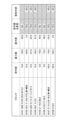
- FIG. 8 is a diagram showing an example of the index angle range presented to the operator in the first embodiment.
- FIG. 8 shows information indicating the minimum and maximum values of the index angle in each block N101 to N108 in a table format.
- the table in FIG. 8 also includes an item "Change command value” for confirming whether to use the program's command value as is or change it. Since FIG. 8 is at the stage of presenting the command value to the operator, "NO" is displayed in the "Change command value” column for each block N101 to N108.
- the "new command value” is the index angle set by the operator, which will be described later, and is blank at this stage.
- the index angle based on the program command is outside the index angle range specified by the range calculation unit 13, that part is displayed in a different manner than when it is within the index angle range.
- the color, pattern, or shape may be changed, such as changing the color of the text, or the fact that the range has been exceeded may be displayed in text.
- the color or pattern of the display of the corresponding item may be changed.
- an expression that changes over time, such as blinking may also be used as a different display method manner.
- the selection result acquisition unit 15 acquires the selection result of whether to use the index angle commanded by the program or to use an index angle within the range presented by the presentation unit 14.
- the person who makes the selection is, for example, an operator.
- the program correction unit 16 performs program correction based on the selection result of the selection result acquisition unit 15.
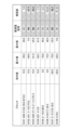
- FIG. 9 is a diagram showing an example of the index angle range changed by the operator in the first embodiment.
- "YES” is set in the "change command value” column for N102 to N104, N107, and N108 among the blocks N101 to N108.
- the index angle of -45° input by the operator is input in the "new command value” column for N102 to N104, N107, and N108 where "YES" is set.
- the operator inputs and sets "change command value” or "new command value” through the input device 51 or an external computer, for example.
- the display in the "change command value” column may be automatically changed from NO to YES.
- the index angles for all blocks for which "YES" was selected are set to -45°, but a different value within the index angle range may be input.
- the selection result acquisition unit 15 acquires as the operator's selection result that an index angle of -45°, different from the command value, is set for blocks N102 to N104, N107, and N108.
- the program correction unit 16 also corrects the program based on the selection result acquired by the selection result acquisition unit 15.
- "B-45" indicating the index angle is added to the block N102, and the index angles of the tools 20 at N102 to N104 become -45°.
- "B-45” is added to N107, which was the block for changing the index angle in the program before correction, and the index angles of the tools 20 at N107 and N108 become -45°.
- the correction process of the program correction unit 16 causes the index angle of the new command value set by the operator to be reflected in the program. This correction is also reflected in the image displayed on the display device 50, resulting in the state shown in FIG. 9. This correction is also displayed in a different display mode from the other parts.
- FIG. 10 is a flowchart showing an example of the flow of the creation support process by the program editing support device 10 of this embodiment.
- the flowchart shown in FIG. 10 is merely an example, and the order and content of the process can be changed as appropriate.
- step S1 the analysis unit 11 analyzes the program to generate command data and transmits it to the range calculation unit 13.
- step S2 the tool shape acquisition unit 12 acquires shape information on the plane on which turning is performed and transmits it to the range calculation unit 13.
- step S3 the range calculation unit 13 executes the above-mentioned process to set the index angle range for each block based on the analysis results (command data) of the analysis unit 11 and the shape information acquired by the tool shape acquisition unit 12.
- step S4 the range calculation unit 13 determines whether or not an index angle range that avoids interference can be set. If the range calculation unit 13 is unable to set an index angle range that avoids interference, the process proceeds to step S8 (step S4; No). In step S8, the presentation unit 14 executes a process of outputting to the display device 50 that interference will occur and that an index range angle cannot be set.
- step S5 the presentation unit 14 transmits image information to the display device 50 to present the index angle range of each block of the program command to the operator.
- step S6 the selection result acquisition unit 15 acquires the selection result of the operator who has confirmed the information presented on the presentation unit 14.
- the selection result here is information based on the operator's input operation.
- step S7 the program correction unit 16 corrects the program command based on the selection result acquired by the selection result acquisition unit 15.
- the program correction unit 16 also causes the presentation unit 14 to execute a process to reflect the correction result in the information displayed on the display device 50.
- the program editing support device 10 of this embodiment described above has the following effects.
- the program editing support device 10 includes an analysis unit 11 that generates command data from a program, the command data including at least a predetermined position of a predetermined point on the movement path of the tool 20 and the relative index angle between the tool 20 and the workpiece W at the predetermined position, a tool shape acquisition unit 12 that acquires shape information of one or more components that make up the tool 20, a range calculation unit 13 that calculates an index angle range in which the workpiece W and the tool 20 do not interfere with each other at the predetermined position based on the command data and the shape information, and a presentation unit 14 that outputs the index angle range.
- the components 21 to 23 are at least one of the tool rest that stores the tool 20, the holder, and the shank and cutting edge of the tool 20.
- the range calculation unit 13 sets the maximum and minimum values of the index angle range when the tool 20 contacts the movement path at a specified position.
- the range calculation unit 13 reflects interference with the structure of the machine performing the turning process in the index angle range.
- the range calculation unit 13 if it is determined that interference between the tool 20 and the workpiece W cannot be avoided even if the index angle is changed, the range calculation unit 13 notifies the user that the interference cannot be avoided.
- the program editing support device 10 of this embodiment further includes a selection result acquisition unit 15 that acquires a selection result indicating that the operator has selected either an index angle specified in the program or an index angle within the index angle range, and a program correction unit 16 that corrects the program based on the selection result.
- the program is automatically corrected, and cutting is performed according to commands based on an index angle that is reliably free of interference.
- the presentation unit 14 displays information indicating that the index angle commanded by the program is within the index angle range and information indicating that the index angle commanded by the program is outside the index angle range in different display modes.
- the program editing support device 10 of the second embodiment has a common configuration with the first embodiment.
- the information presented by the presentation unit 14 and the format input by the operator are different.
- the process of displaying the recommended values by the presentation unit 14 will be described with reference to Figs. 11 and 12.
- FIG. 11 is a diagram showing an example of the index angle range and recommended values presented to the operator in the second embodiment.
- "Change command value" in FIG. 8 and FIG. 9 in the first embodiment has been changed to "Use recommended value”
- the "New command value” item has been changed to "Recommended value.”
- the presentation unit 14 of the second embodiment presents the index angle range and one or more index angles from the calculated range as recommended values on the display device 50 to the operator.
- the presentation unit 14 acquires the representative value of the index angle range acquired by the range calculation unit 13 as the recommended value.
- the representative value may be, for example, the median or average value within the index angle range of the block, or the maximum or minimum value of the index angle range may be used as is.
- the presentation unit 14 presents the median value of the index angle range to the operator as the recommended value.
- the recommended value is calculated for each of blocks N101 to N108.
- the presentation unit 14 also executes a process of displaying blocks in which the index angle based on the command value falls outside the calculated index angle range in a manner that is different from blocks that are within the index angle range.
- the presentation unit 14 changes the color of the text in the "Use recommended value" column of the block and displays the recommended value on the display device 50.
- FIG. 12 is a diagram showing an example of an index angle range changed by an operator in the second embodiment.
- the example in FIG. 12 shows a state in which "Use recommended value" for blocks N102 to N104 and N107 has been changed to YES by the operator.
- the selection result acquisition unit 15 acquires as the operator's selection result that the recommended value rather than the command value will be set for blocks N102 to N104 and N107 where YES is set.
- the index angle command value in a certain block is replaced with a recommended value, and the "Use recommended value" field in the subsequent block is set to "NO".
- the program correction unit 16 interprets that the operator does not intend to change the block in which NO is set, and sets a new index angle to be applied in the program before the change, rather than the recommended value.
- the program correction unit 16 sets the index angle to the recommended value in N107 in which "YES” is set, and sets the index angle to be applied when the program before the change is executed in N108 in which "NO” is set, rather than applying the recommended value of N107.
- "B-30.0" is added to the block of N108.
- the second embodiment provides the following advantages in addition to the advantages of the first embodiment.
- the presentation unit 14 presents, in addition to the index angle range, one or more index angles from the index angle range as recommended values.
- the presenter 14 presents the median, maximum, minimum or average value of the index angle range as the recommended value.
- a program editing support device that supports the creation of a program for turning a workpiece (W) using a tool (20), an analysis unit (11) that generates command data including at least a predetermined position of a predetermined point on a movement path of the tool (20) from the program and a relative index angle between the tool (20) and the workpiece (W) at the predetermined position; a tool shape acquisition unit (12) for acquiring shape information of one or more components (21) to (23) constituting the tool (20); a range calculation unit (13) that calculates an index angle range in which the workpiece (W) and the tool (20) do not interfere with each other at the predetermined position based on the command data and the shape information;
- a program editing support device comprising: a presentation unit (14) that outputs the index angle range.
- the presenting unit (14) presents, in addition to the index angle range, one or more index angles within the index angle range as recommended values.
- the presenting unit (14) presents any one of a median value, a maximum value, a minimum value, or an average value of the index angle range as the recommended value.
- the components include at least one of a tool rest that stores the tool (20), a holder, a shank, and a cutting edge of the tool (20).
- the range calculation unit (13) sets maximum and minimum values of the index angle range when the tool (20) comes into contact with the movement path at the predetermined position.
- the range calculation unit (13) reflects interference with a structure of the machine performing the turning process in the index angle range.
- a selection result acquisition unit that acquires a selection result indicating that an operator has selected either the index angle specified in the program or an index angle within the index angle range;
- the program modifying unit further includes a program modifying unit (16) for modifying the program based on the selection result.
- the presentation unit (14) Information indicating that the index angle commanded by the program is within the index angle range; and Information indicating that the index angle commanded by the program is outside the index angle range; and are displayed in different display modes.
Landscapes
- Engineering & Computer Science (AREA)
- Physics & Mathematics (AREA)
- Human Computer Interaction (AREA)
- Manufacturing & Machinery (AREA)
- General Physics & Mathematics (AREA)
- Automation & Control Theory (AREA)
- Geometry (AREA)
- Numerical Control (AREA)
Priority Applications (4)
| Application Number | Priority Date | Filing Date | Title |
|---|---|---|---|
| PCT/JP2023/013232 WO2024201908A1 (ja) | 2023-03-30 | 2023-03-30 | プログラム編集支援装置 |
| DE112023005268.9T DE112023005268T5 (de) | 2023-03-30 | 2023-03-30 | Programmeditierunterstützungsvorrichtung |
| CN202380091754.XA CN120604185A (zh) | 2023-03-30 | 2023-03-30 | 程序编辑辅助装置 |
| JP2025509507A JPWO2024201908A1 (https=) | 2023-03-30 | 2023-03-30 |
Applications Claiming Priority (1)
| Application Number | Priority Date | Filing Date | Title |
|---|---|---|---|
| PCT/JP2023/013232 WO2024201908A1 (ja) | 2023-03-30 | 2023-03-30 | プログラム編集支援装置 |
Publications (1)
| Publication Number | Publication Date |
|---|---|
| WO2024201908A1 true WO2024201908A1 (ja) | 2024-10-03 |
Family
ID=92903694
Family Applications (1)
| Application Number | Title | Priority Date | Filing Date |
|---|---|---|---|
| PCT/JP2023/013232 Ceased WO2024201908A1 (ja) | 2023-03-30 | 2023-03-30 | プログラム編集支援装置 |
Country Status (4)
| Country | Link |
|---|---|
| JP (1) | JPWO2024201908A1 (https=) |
| CN (1) | CN120604185A (https=) |
| DE (1) | DE112023005268T5 (https=) |
| WO (1) | WO2024201908A1 (https=) |
Cited By (1)
| Publication number | Priority date | Publication date | Assignee | Title |
|---|---|---|---|---|
| JP7810843B1 (ja) * | 2025-04-09 | 2026-02-03 | Dmg森精機株式会社 | 情報処理装置、情報処理方法およびソフトウェア |
Citations (3)
| Publication number | Priority date | Publication date | Assignee | Title |
|---|---|---|---|---|
| JP2006235764A (ja) * | 2005-02-22 | 2006-09-07 | Hitachi Ltd | Cam装置、工具軌跡作成方法、切削終了動作設定方法および工具軌跡作成プログラム |
| JP2011183528A (ja) * | 2010-03-10 | 2011-09-22 | Mitsubishi Electric Corp | 自動プログラミング装置、およびその動作プログラム |
| JP2013196130A (ja) * | 2012-03-16 | 2013-09-30 | Kobe Univ | 加工作業支援方法および加工作業支援装置 |
-
2023
- 2023-03-30 CN CN202380091754.XA patent/CN120604185A/zh active Pending
- 2023-03-30 DE DE112023005268.9T patent/DE112023005268T5/de active Pending
- 2023-03-30 JP JP2025509507A patent/JPWO2024201908A1/ja active Pending
- 2023-03-30 WO PCT/JP2023/013232 patent/WO2024201908A1/ja not_active Ceased
Patent Citations (3)
| Publication number | Priority date | Publication date | Assignee | Title |
|---|---|---|---|---|
| JP2006235764A (ja) * | 2005-02-22 | 2006-09-07 | Hitachi Ltd | Cam装置、工具軌跡作成方法、切削終了動作設定方法および工具軌跡作成プログラム |
| JP2011183528A (ja) * | 2010-03-10 | 2011-09-22 | Mitsubishi Electric Corp | 自動プログラミング装置、およびその動作プログラム |
| JP2013196130A (ja) * | 2012-03-16 | 2013-09-30 | Kobe Univ | 加工作業支援方法および加工作業支援装置 |
Cited By (1)
| Publication number | Priority date | Publication date | Assignee | Title |
|---|---|---|---|---|
| JP7810843B1 (ja) * | 2025-04-09 | 2026-02-03 | Dmg森精機株式会社 | 情報処理装置、情報処理方法およびソフトウェア |
Also Published As
| Publication number | Publication date |
|---|---|
| JPWO2024201908A1 (https=) | 2024-10-03 |
| DE112023005268T5 (de) | 2025-11-13 |
| CN120604185A (zh) | 2025-09-05 |
Similar Documents
| Publication | Publication Date | Title |
|---|---|---|
| JP6335925B2 (ja) | 工作機械の制御装置 | |
| US6597142B2 (en) | Apparatus and method for setting control parameters of machining apparatus | |
| US20160151913A1 (en) | Robot programming apparatus for teaching machining operation to robot | |
| EP2985664B1 (en) | Offset number setting device | |
| WO2024201908A1 (ja) | プログラム編集支援装置 | |
| EP2915625B1 (en) | Machine tool control device and machine tool | |
| JP2005288563A (ja) | 加工プログラム作成方法、及び加工プログラム作成装置 | |
| KR100898034B1 (ko) | 공구경로 수정 방법 | |
| JP5813931B2 (ja) | 教示データの修正システム | |
| WO2016051555A1 (ja) | 数値制御装置 | |
| JPH058152A (ja) | 数値制御装置 | |
| EP4542317A1 (en) | Information processing device and information processing program | |
| KR100898035B1 (ko) | 공구경로 수정 방법 | |
| JPH10293606A (ja) | 工作機械における切削制御装置 | |
| JP7824325B2 (ja) | 情報処理装置、工作機械の制御装置、及びコンピュータプログラム | |
| JPH08106311A (ja) | 数値制御装置 | |
| WO2024201920A1 (ja) | 情報生成装置及び情報表示装置 | |
| JP2020001139A (ja) | ワイヤ放電加工機の制御装置 | |
| JP4770076B2 (ja) | 数値制御装置 | |
| JP4343072B2 (ja) | Nc加工シミュレーション装置 | |
| KR100872394B1 (ko) | 공구경로 수정 방법 | |
| US12496673B2 (en) | Machine tool and method of deciding tool moving path | |
| US20240342805A1 (en) | Machine tool and moving position determining method | |
| JP2007172325A (ja) | 自由曲線加工法および数値制御装置 | |
| WO2024232104A1 (ja) | 工作機械の表示装置及びプログラム |
Legal Events
| Date | Code | Title | Description |
|---|---|---|---|
| 121 | Ep: the epo has been informed by wipo that ep was designated in this application |
Ref document number: 23930546 Country of ref document: EP Kind code of ref document: A1 |
|
| WWE | Wipo information: entry into national phase |
Ref document number: 202380091754.X Country of ref document: CN |
|
| WWE | Wipo information: entry into national phase |
Ref document number: 112023005268 Country of ref document: DE |
|
| WWP | Wipo information: published in national office |
Ref document number: 202380091754.X Country of ref document: CN |
|
| ENP | Entry into the national phase |
Ref document number: 2025509507 Country of ref document: JP Kind code of ref document: A |
|
| WWE | Wipo information: entry into national phase |
Ref document number: 2025509507 Country of ref document: JP |
|
| WWP | Wipo information: published in national office |
Ref document number: 112023005268 Country of ref document: DE |
|
| 122 | Ep: pct application non-entry in european phase |
Ref document number: 23930546 Country of ref document: EP Kind code of ref document: A1 |