WO2024201898A1 - バッテリユニット - Google Patents
バッテリユニット Download PDFInfo
- Publication number
- WO2024201898A1 WO2024201898A1 PCT/JP2023/013194 JP2023013194W WO2024201898A1 WO 2024201898 A1 WO2024201898 A1 WO 2024201898A1 JP 2023013194 W JP2023013194 W JP 2023013194W WO 2024201898 A1 WO2024201898 A1 WO 2024201898A1
- Authority
- WO
- WIPO (PCT)
- Prior art keywords
- bus bar
- battery
- junction box
- center
- motor
- Prior art date
- Legal status (The legal status is an assumption and is not a legal conclusion. Google has not performed a legal analysis and makes no representation as to the accuracy of the status listed.)
- Ceased
Links
Images


Classifications
-
- B—PERFORMING OPERATIONS; TRANSPORTING
- B60—VEHICLES IN GENERAL
- B60R—VEHICLES, VEHICLE FITTINGS, OR VEHICLE PARTS, NOT OTHERWISE PROVIDED FOR
- B60R16/00—Electric or fluid circuits specially adapted for vehicles and not otherwise provided for; Arrangement of elements of electric or fluid circuits specially adapted for vehicles and not otherwise provided for
- B60R16/02—Electric or fluid circuits specially adapted for vehicles and not otherwise provided for; Arrangement of elements of electric or fluid circuits specially adapted for vehicles and not otherwise provided for electric constitutive elements
- B60R16/03—Electric or fluid circuits specially adapted for vehicles and not otherwise provided for; Arrangement of elements of electric or fluid circuits specially adapted for vehicles and not otherwise provided for electric constitutive elements for supply of electrical power to vehicle subsystems or for
- B60R16/033—Electric or fluid circuits specially adapted for vehicles and not otherwise provided for; Arrangement of elements of electric or fluid circuits specially adapted for vehicles and not otherwise provided for electric constitutive elements for supply of electrical power to vehicle subsystems or for characterised by the use of electrical cells or batteries
-
- B—PERFORMING OPERATIONS; TRANSPORTING
- B60—VEHICLES IN GENERAL
- B60K—ARRANGEMENT OR MOUNTING OF PROPULSION UNITS OR OF TRANSMISSIONS IN VEHICLES; ARRANGEMENT OR MOUNTING OF PLURAL DIVERSE PRIME-MOVERS IN VEHICLES; AUXILIARY DRIVES FOR VEHICLES; INSTRUMENTATION OR DASHBOARDS FOR VEHICLES; ARRANGEMENTS IN CONNECTION WITH COOLING, AIR INTAKE, GAS EXHAUST OR FUEL SUPPLY OF PROPULSION UNITS IN VEHICLES
- B60K1/00—Arrangement or mounting of electrical propulsion units
-
- B—PERFORMING OPERATIONS; TRANSPORTING
- B60—VEHICLES IN GENERAL
- B60K—ARRANGEMENT OR MOUNTING OF PROPULSION UNITS OR OF TRANSMISSIONS IN VEHICLES; ARRANGEMENT OR MOUNTING OF PLURAL DIVERSE PRIME-MOVERS IN VEHICLES; AUXILIARY DRIVES FOR VEHICLES; INSTRUMENTATION OR DASHBOARDS FOR VEHICLES; ARRANGEMENTS IN CONNECTION WITH COOLING, AIR INTAKE, GAS EXHAUST OR FUEL SUPPLY OF PROPULSION UNITS IN VEHICLES
- B60K1/00—Arrangement or mounting of electrical propulsion units
- B60K1/02—Arrangement or mounting of electrical propulsion units comprising more than one electric motor
-
- B—PERFORMING OPERATIONS; TRANSPORTING
- B60—VEHICLES IN GENERAL
- B60K—ARRANGEMENT OR MOUNTING OF PROPULSION UNITS OR OF TRANSMISSIONS IN VEHICLES; ARRANGEMENT OR MOUNTING OF PLURAL DIVERSE PRIME-MOVERS IN VEHICLES; AUXILIARY DRIVES FOR VEHICLES; INSTRUMENTATION OR DASHBOARDS FOR VEHICLES; ARRANGEMENTS IN CONNECTION WITH COOLING, AIR INTAKE, GAS EXHAUST OR FUEL SUPPLY OF PROPULSION UNITS IN VEHICLES
- B60K1/00—Arrangement or mounting of electrical propulsion units
- B60K1/04—Arrangement or mounting of electrical propulsion units of the electric storage means for propulsion
-
- B—PERFORMING OPERATIONS; TRANSPORTING
- B60—VEHICLES IN GENERAL
- B60R—VEHICLES, VEHICLE FITTINGS, OR VEHICLE PARTS, NOT OTHERWISE PROVIDED FOR
- B60R16/00—Electric or fluid circuits specially adapted for vehicles and not otherwise provided for; Arrangement of elements of electric or fluid circuits specially adapted for vehicles and not otherwise provided for
- B60R16/02—Electric or fluid circuits specially adapted for vehicles and not otherwise provided for; Arrangement of elements of electric or fluid circuits specially adapted for vehicles and not otherwise provided for electric constitutive elements
- B60R16/023—Electric or fluid circuits specially adapted for vehicles and not otherwise provided for; Arrangement of elements of electric or fluid circuits specially adapted for vehicles and not otherwise provided for electric constitutive elements for transmission of signals between vehicle parts or subsystems
- B60R16/0238—Electrical distribution centers
-
- H—ELECTRICITY
- H01—ELECTRIC ELEMENTS
- H01M—PROCESSES OR MEANS, e.g. BATTERIES, FOR THE DIRECT CONVERSION OF CHEMICAL ENERGY INTO ELECTRICAL ENERGY
- H01M10/00—Secondary cells; Manufacture thereof
- H01M10/60—Heating or cooling; Temperature control
- H01M10/61—Types of temperature control
- H01M10/613—Cooling or keeping cold
-
- H—ELECTRICITY
- H01—ELECTRIC ELEMENTS
- H01M—PROCESSES OR MEANS, e.g. BATTERIES, FOR THE DIRECT CONVERSION OF CHEMICAL ENERGY INTO ELECTRICAL ENERGY
- H01M10/00—Secondary cells; Manufacture thereof
- H01M10/60—Heating or cooling; Temperature control
- H01M10/62—Heating or cooling; Temperature control specially adapted for specific applications
- H01M10/625—Vehicles
-
- H—ELECTRICITY
- H01—ELECTRIC ELEMENTS
- H01M—PROCESSES OR MEANS, e.g. BATTERIES, FOR THE DIRECT CONVERSION OF CHEMICAL ENERGY INTO ELECTRICAL ENERGY
- H01M10/00—Secondary cells; Manufacture thereof
- H01M10/60—Heating or cooling; Temperature control
- H01M10/65—Means for temperature control structurally associated with the cells
- H01M10/655—Solid structures for heat exchange or heat conduction
- H01M10/6556—Solid parts with flow channel passages or pipes for heat exchange
-
- H—ELECTRICITY
- H01—ELECTRIC ELEMENTS
- H01M—PROCESSES OR MEANS, e.g. BATTERIES, FOR THE DIRECT CONVERSION OF CHEMICAL ENERGY INTO ELECTRICAL ENERGY
- H01M50/00—Constructional details or processes of manufacture of the non-active parts of electrochemical cells other than fuel cells, e.g. hybrid cells
- H01M50/20—Mountings; Secondary casings or frames; Racks, modules or packs; Suspension devices; Shock absorbers; Transport or carrying devices; Holders
- H01M50/204—Racks, modules or packs for multiple batteries or multiple cells
- H01M50/207—Racks, modules or packs for multiple batteries or multiple cells characterised by their shape
- H01M50/209—Racks, modules or packs for multiple batteries or multiple cells characterised by their shape adapted for prismatic or rectangular cells
-
- H—ELECTRICITY
- H01—ELECTRIC ELEMENTS
- H01M—PROCESSES OR MEANS, e.g. BATTERIES, FOR THE DIRECT CONVERSION OF CHEMICAL ENERGY INTO ELECTRICAL ENERGY
- H01M50/00—Constructional details or processes of manufacture of the non-active parts of electrochemical cells other than fuel cells, e.g. hybrid cells
- H01M50/20—Mountings; Secondary casings or frames; Racks, modules or packs; Suspension devices; Shock absorbers; Transport or carrying devices; Holders
- H01M50/249—Mountings; Secondary casings or frames; Racks, modules or packs; Suspension devices; Shock absorbers; Transport or carrying devices; Holders specially adapted for aircraft or vehicles, e.g. cars or trains
-
- H—ELECTRICITY
- H01—ELECTRIC ELEMENTS
- H01M—PROCESSES OR MEANS, e.g. BATTERIES, FOR THE DIRECT CONVERSION OF CHEMICAL ENERGY INTO ELECTRICAL ENERGY
- H01M50/00—Constructional details or processes of manufacture of the non-active parts of electrochemical cells other than fuel cells, e.g. hybrid cells
- H01M50/20—Mountings; Secondary casings or frames; Racks, modules or packs; Suspension devices; Shock absorbers; Transport or carrying devices; Holders
- H01M50/296—Mountings; Secondary casings or frames; Racks, modules or packs; Suspension devices; Shock absorbers; Transport or carrying devices; Holders characterised by terminals of battery packs
-
- H—ELECTRICITY
- H01—ELECTRIC ELEMENTS
- H01M—PROCESSES OR MEANS, e.g. BATTERIES, FOR THE DIRECT CONVERSION OF CHEMICAL ENERGY INTO ELECTRICAL ENERGY
- H01M50/00—Constructional details or processes of manufacture of the non-active parts of electrochemical cells other than fuel cells, e.g. hybrid cells
- H01M50/50—Current conducting connections for cells or batteries
- H01M50/572—Means for preventing undesired use or discharge
- H01M50/574—Devices or arrangements for the interruption of current
-
- B—PERFORMING OPERATIONS; TRANSPORTING
- B60—VEHICLES IN GENERAL
- B60K—ARRANGEMENT OR MOUNTING OF PROPULSION UNITS OR OF TRANSMISSIONS IN VEHICLES; ARRANGEMENT OR MOUNTING OF PLURAL DIVERSE PRIME-MOVERS IN VEHICLES; AUXILIARY DRIVES FOR VEHICLES; INSTRUMENTATION OR DASHBOARDS FOR VEHICLES; ARRANGEMENTS IN CONNECTION WITH COOLING, AIR INTAKE, GAS EXHAUST OR FUEL SUPPLY OF PROPULSION UNITS IN VEHICLES
- B60K1/00—Arrangement or mounting of electrical propulsion units
- B60K2001/003—Arrangement or mounting of electrical propulsion units with means for cooling the electrical propulsion units
- B60K2001/005—Arrangement or mounting of electrical propulsion units with means for cooling the electrical propulsion units the electric storage means
-
- H—ELECTRICITY
- H01—ELECTRIC ELEMENTS
- H01M—PROCESSES OR MEANS, e.g. BATTERIES, FOR THE DIRECT CONVERSION OF CHEMICAL ENERGY INTO ELECTRICAL ENERGY
- H01M2220/00—Batteries for particular applications
- H01M2220/20—Batteries in motive systems, e.g. vehicle, ship, plane
-
- Y—GENERAL TAGGING OF NEW TECHNOLOGICAL DEVELOPMENTS; GENERAL TAGGING OF CROSS-SECTIONAL TECHNOLOGIES SPANNING OVER SEVERAL SECTIONS OF THE IPC; TECHNICAL SUBJECTS COVERED BY FORMER USPC CROSS-REFERENCE ART COLLECTIONS [XRACs] AND DIGESTS
- Y02—TECHNOLOGIES OR APPLICATIONS FOR MITIGATION OR ADAPTATION AGAINST CLIMATE CHANGE
- Y02E—REDUCTION OF GREENHOUSE GAS [GHG] EMISSIONS, RELATED TO ENERGY GENERATION, TRANSMISSION OR DISTRIBUTION
- Y02E60/00—Enabling technologies; Technologies with a potential or indirect contribution to GHG emissions mitigation
- Y02E60/10—Energy storage using batteries
Definitions
- the present invention relates to a battery unit installed in a vehicle.
- the positive and negative terminals of the battery are connected to one of the electrical junction boxes.
- the electrical junction box to which the positive and negative terminals are connected is damaged, there is a risk that the battery will be short-circuited.
- the present invention aims to reduce battery short circuits.
- a battery unit includes a battery, a battery case that houses the battery, a front junction box that is provided on the front side in the longitudinal direction of the vehicle and distributes power to the front motor, a rear junction box that is provided on the rear side in the longitudinal direction and distributes power to the rear motor, a front bus bar that connects one of the positive and negative terminals of the battery to the front junction box, a rear bus bar that connects the other of the positive and negative terminals of the battery to the rear junction box, and a center bus bar that connects the front junction box and the rear junction box.
- the present invention can reduce battery short circuits.
- FIG. 1 is a diagram showing the configuration of a vehicle.
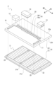
- FIG. 2 is an exploded perspective view illustrating the configuration of the battery module.
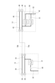
- FIG. 3 is a diagram illustrating the configuration of the front junction box and the rear junction box.
- FIG. 4 is a diagram for explaining the electrical configuration of the front junction box and the rear junction box.
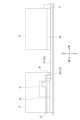
- FIG. 5 is a diagram for explaining the connection relationship between the center bus bar, the system main relay, and the front junction box.
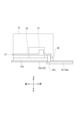
- FIG. 6 is a diagram illustrating a modified example of the connection relationship between the center bus bar and the front junction box.
- Overview of vehicle configuration> 1 is a diagram showing a configuration of a vehicle 1.
- the front-rear direction of the vehicle 1 will be simply referred to as the front-rear direction
- the left-right direction of the vehicle 1 will be simply referred to as the left-right direction.
- the vehicle 1 is an electric vehicle equipped with a battery module 2, a front motor 3, a front inverter 4, a rear motor 5, and a rear inverter 6.
- the battery module 2 is disposed, for example, in the center in the front-rear direction and below the floor.
- the battery module 2 includes a battery 11, a front junction box 12, a rear junction box 13, and an electrical device 14, as described in detail below.
- the battery 11 is capable of storing power (electricity) to be supplied to the front motor 3 and the rear motor 5 .
- the front junction box 12 is connected to the battery 11 and the front inverter 4 , and distributes power from the battery 11 to the front motor 3 via the front inverter 4 .
- the rear junction box 13 is connected to the battery 11 and the rear inverter 6 , and distributes power from the battery 11 to the rear motor 5 via the rear inverter 6 .
- the electrical device 14 is, for example, a DC-DC converter that generates a voltage of 100 V, or an OBC (On Board Charger) that can be connected to an external charging device, and is connected to the battery 11 .
- the front motor 3 and the rear motor 5 are power sources for propelling the vehicle 1 and are, for example, three-phase AC motors.
- the front motor 3 is connected to the front wheels.
- the front motor 3 When power is supplied from the battery 11 via the front junction box 12 and the front inverter 4, the front motor 3 generates driving force and transmits the driving force to the front wheels to rotate the front wheels.
- the rear motor 5 is connected to the rear wheels. When power is supplied from the battery 11 via the rear junction box 13 and the rear inverter 6, the rear motor 5 generates driving force and transmits the driving force to the rear wheels to rotate the rear wheels.
- the front motor 3 and the rear motor 5 generate electricity (power) by performing regenerative operation.
- the electricity generated by the regenerative operation of the front motor 3 and the rear motor 5 is supplied to the battery 11 via the front inverter 4 and the rear inverter 6, respectively, to charge the battery 11.
- the front inverter 4 converts the DC current supplied from the battery 11 into three-phase AC current and supplies it to the front motor 3.
- the front inverter 4 converts the AC current supplied from the front motor 3 into DC current and supplies it to the battery 11, thereby charging the battery 11.
- the rear inverter 6 converts the DC current supplied from the battery 11 into a three-phase AC current and supplies it to the rear motor 5.
- the rear inverter 6 converts the AC current supplied from the rear motor 5 into a DC current and supplies it to the battery 11, thereby charging the battery 11.
- Fig. 2 is an exploded perspective view illustrating the configuration of the battery module 2.
- the battery module 2 includes a battery 11, a front junction box 12, a rear junction box 13, and an electrical device 14, as well as a battery case 15, a front bus bar 16, a rear bus bar 17, and a center bus bar 18.
- the battery case 15 includes a battery tray 21 and a battery cover 22 .
- the battery tray 21 is made of, for example, iron or aluminum.
- the battery tray 21 is integrally formed with a flat bottom 21a and a frame 21b that protrudes upward from the bottom 21a to form a substantially rectangular frame.
- the space surrounded by the bottom 21a and the frame 21b is the storage space that stores the battery 11.
- the battery cover 22 is made of, for example, a resin material or an aluminum material.
- the battery cover 22 is integrally formed with a flat ceiling portion 22a that serves as the ceiling, and a frame portion 22b that protrudes downward from the ceiling portion 22a to form a roughly rectangular frame shape.
- the battery case 15 is housed in a space surrounded by the ceiling 22a and frame 22b of the battery cover 22 so that the frame 21b of the battery tray 21 is covered. In other words, the battery case 15 covers the battery 11 with the battery tray 21 and battery cover 22 without exposing it to the outside.
- the battery 11 is composed of multiple battery cells 23.
- the battery cells 23 are, for example, lithium ion batteries, and can be used by repeatedly charging and discharging.
- the battery cells 23 are formed into a roughly rectangular parallelepiped shape and are arranged side by side in the front-to-back and left-to-right directions inside the battery case 15.
- the vertical length of the battery cells 23, i.e., the height of the battery cells 23, is roughly the same as the vertical length of the frame portion 21b of the battery tray 21.
- the battery cells 23 arranged in the battery case 15 are connected in series with adjacent battery cells 23. This allows the battery 11 to supply high-voltage power, for example, 200V or 400V.
- the battery cell 23 arranged on the most positive side in the series direction is provided with a positive terminal 24. Also, among the multiple battery cells 23 connected in series, the battery cell 23 arranged on the most negative side in the series direction is provided with a negative terminal 25.
- the positive electrode terminal 24 and the negative electrode terminal 25 are each provided on the battery cell 23 so as to protrude upward.
- the ceiling portion 22 a of the battery cover 22 is formed with through holes (not shown) at positions facing the positive electrode terminal 24 and the negative electrode terminal 25 .
- the positive terminal 24 and the negative terminal 25 pass through through holes formed in the ceiling portion 22a of the battery cover 22 and protrude upward from the ceiling portion 22a.
- the ceiling portion 22a is provided with a front junction box 12, a rear junction box 13, electrical equipment 14, a front bus bar 16, a rear bus bar 17, and a center bus bar 18.
- the front junction box 12 is located on the front-rear direction front side of the ceiling portion 22a and in the center in the left-right direction. At this time, the front junction box 12 is located so that it fits entirely inside the outer edge of the battery case 15.
- the rear junction box 13 is located on the rear side of the ceiling portion 22a in the front-to-rear direction and in the center in the left-to-right direction. At this time, the rear junction box 13 is positioned so that it fits entirely inside the outer edge of the battery case 15.
- the front bus bar 16 is disposed on the front side of the ceiling portion 22a in the front-rear direction, along the left-right direction so that both ends are connected to the positive terminal 24 protruding above the ceiling portion 22a and the front junction box 12.
- the front bus bar 16 is insulated from the outside by being covered with, for example, a resin material.
- the rear bus bar 17 is located on the rear side of the ceiling portion 22a in the front-to-rear direction, and is arranged in the left-right direction so that both ends are connected to the negative terminal 25 protruding above the ceiling portion 22a and the rear junction box 13.
- the rear bus bar 17 is insulated from the outside by being covered with, for example, a resin material.
- the center bus bar 18 is composed of a positive electrode side center bus bar 18a and a negative electrode side center bus bar 18b.
- the positive and negative center bus bars 18a, 18b are disposed in the center of the ceiling portion 22a in the left-right direction, along the front-rear direction, such that both ends are connected to the front junction box 12 and the rear junction box 13.
- the positive and negative center bus bars 18a, 18b are insulated from the outside by being covered with, for example, a resin material.
- the positive and negative center bus bars 18a, 18b are disposed approximately parallel to each other and spaced a predetermined distance apart.
- the electrical equipment 14 is located in the center of the ceiling portion 22a in the front-rear and left-right directions, and is disposed on the center bus bar 18 via a cooling plate 26. As will be described in detail later, the electrical equipment 14 is connected to the positive center bus bar 18a and the negative center bus bar 18b.
- the cooling plate 26 is structured so that a cooling medium flows inside, for example, and cools the electrical equipment 14 arranged above it.
- the cooling plate 26 is also positioned so that it abuts against the center bus bar 18, thereby cooling the center bus bar 18 as well.
- FIG. 3 is a diagram explaining the configuration of the front junction box 12 and the rear junction box 13. Note that FIG. 3 illustrates only a portion of the configuration of the battery module 2, and omits a portion of the configuration of the front junction box 12 and the rear junction box 13.
- the front junction box 12 includes a system main relay 31, a first front internal bus bar 32, a second front internal bus bar 33, a third front internal bus bar 34, fastening members 35, 36, 37, and connectors 38, 39.
- the first front internal bus bar 32 has one end connected to the front bus bar 16 via a fastening member 35 and the other end connected to the system main relay 31 .
- the second front internal bus bar 33 is formed so as to branch in three directions, with one end connected to the system main relay 31, a second end connected to the positive electrode side center bus bar 18a via a fastening member 36, and a third end connected to a connector 38.
- the first front internal bus bar 32 and the second front internal bus bar 33 can be electrically connected by the system main relay 31.
- the third front internal bus bar 34 has one end connected to the negative electrode side center bus bar 18 b via a fastening member 37 and the other end connected to a connector 39 .
- the system main relay 31 is configured to be able to electrically connect and disconnect the positive terminal 24 of the battery 11, which is connected via the front bus bar 16, the fastening member 35, and the first front internal bus bar 32, to the second front internal bus bar 33.
- the fastening members 35, 36, and 37 are constituted by bolts and nuts made of conductive metal material, for example, and fasten the pair of bus bars together.
- the connectors 38 , 39 are connected to the front inverter 4 .
- the rear junction box 13 includes a system main relay 41, a first rear internal bus bar 42, a second rear internal bus bar 43, a third rear internal bus bar 44, fastening members 45, 46, 47, and connectors 48, 49.
- the first rear internal bus bar 42 has one end connected to the rear bus bar 17 via a fastening member 45 and the other end connected to the system main relay 41 .
- the second rear internal bus bar 43 is formed so as to branch in three directions, with one end connected to the system main relay 41, a second end connected to the negative electrode side center bus bar 18b via a fastening member 46, and a third end connected to a connector 48.
- the first rear internal bus bar 42 and the second rear internal bus bar 43 can be electrically connected within the system main relay 41.
- the third rear internal bus bar 44 has one end connected to the positive electrode side center bus bar 18 a via a fastening member 47 and the other end connected to a connector 49 .
- the system main relay 41 is configured to be able to electrically connect and disconnect the negative terminal 25 of the battery 11, which is connected via the rear bus bar 17, the fastening member 45, and the first rear internal bus bar 42, to the second rear internal bus bar 43.
- the fastening members 45, 46, 47 are constituted by bolts and nuts made of conductive metal material, for example, and fasten the pair of bus bars together.
- the connectors 48 , 49 are connected to the rear inverter 6 .
- the electrical device 14 is provided with connectors 61 and 62.
- the electrical device 14 is connected to the positive center bus bar 18a via the connector 61, and is connected to the negative center bus bar 18b via the connector 62. This makes it possible to connect the battery 11 and the electrical device 14 without installing new electrical wiring to connect the battery 11 and the electrical device 14, thereby reducing the number of parts and making the device smaller.
- FIG. 4 is a diagram explaining the electrical configuration of the front junction box 12 and the rear junction box 13. Note that FIG. 4 only illustrates a portion of the configuration of the battery module 2. Also, in FIG. 4, for ease of explanation, the positive electrode side center bus bar 18a and the negative electrode side center bus bar 18b are crossed midway.
- the front junction box 12 includes a fuse 40 in addition to a system main relay 31.
- the system main relay 31 and the fuse 40 are connected in series between the first front internal bus bar 32 and the second front internal bus bar 33.
- the system main relay 31 can electrically connect and disconnect the first front internal bus bar 32 and the second front internal bus bar 33, and is controlled by an ECU (Electronic Control Unit) (not shown).
- ECU Electronic Control Unit
- the fuse 40 breaks and disconnects the first front internal bus bar 32 and the second front internal bus bar 33 .
- the rear junction box 13 includes a system main relay 41 , as well as a relay 50 , a resistor 51 , and an ammeter 52 .
- the system main relay 41 and the relay 50 are connected in parallel between the first rear internal bus bar 42 and the second rear internal bus bar 43 .
- the resistor 51 is connected in series to the relay 50 and in parallel to the system main relay 41 .
- the ammeter 52 is disposed closer to the first rear internal bus bar 42 than the system main relay 41 , the relay 50 , and the resistor 51 , and measures the current value of the current flowing through the first rear internal bus bar 42 .
- the system main relay 41 and relay 50 can electrically connect and disconnect the first rear internal bus bar 42 and the second rear internal bus bar 43, and are controlled by an ECU (not shown).
- the ECU electrically connects the first front internal bus bar 32 and the second front internal bus bar 33 by turning on the system main relay 31.
- the ECU also electrically connects the first rear internal bus bar 42 and the second rear internal bus bar 43 by turning on the system main relay 41.
- the ECU also electrically connects the first rear internal bus bar 42 and the second rear internal bus bar 43 via resistor 51 by turning on relay 50.
- the positive terminal 24 of the battery 11 is then connected to the front motor 3 via the front bus bar 16, fastening member 35, first front internal bus bar 32, system main relay 31, second front internal bus bar 33, connector 38, and front inverter 4.
- the negative terminal 25 of the battery 11 is then connected to the front motor 3 via the rear bus bar 17, fastening member 45, first rear internal bus bar 42, system main relay 41, second rear internal bus bar 43, fastening member 46, negative center bus bar 18b, fastening member 37, third front internal bus bar 34, connector 39, and front inverter 4. This allows power from the battery 11 to be supplied to the front motor 3.
- the positive terminal 24 of the battery 11 is connected to the rear motor 5 via the front bus bar 16, fastening member 35, first front internal bus bar 32, system main relay 31, second front internal bus bar 33, fastening member 36, positive center bus bar 18a, fastening member 47, third rear internal bus bar 44, connector 49, and rear inverter 6.
- the negative terminal 25 of the battery 11 is connected to the rear motor 5 via the rear bus bar 17, fastening member 45, first rear internal bus bar 42, system main relay 41, second rear internal bus bar 43, connector 48, and rear inverter 6. This allows power from the battery 11 to be supplied to the rear motor 5.
- the battery 11 and the electrical device 14 can be electrically connected in a similar manner.
- the ECU electrically disconnects the first front internal bus bar 32 and the second front internal bus bar 33 by turning off the system main relay 31.
- the ECU also electrically connects the first rear internal bus bar 42 and the second rear internal bus bar 43 by turning off the system main relay 41 and relay 50. In this way, the ECU electrically disconnects the front motor 3, rear motor 5, and electrical device 14 from the battery 11.
- FIG. 5 is a diagram explaining the connection relationship between the center bus bar 18, the system main relay 31, and the front junction box 12. Note that FIG. 5 illustrates the front junction box 12, part of the configuration of the electrical device 14, and the positive center bus bar 18a, and omits other configuration.
- the center bus bar 18 (positive pole side center bus bar 18a in the figure) is arranged so as to be in close contact with the upper surface of the ceiling portion 22a.
- one end of the positive pole side center bus bar 18a is inserted up to just above the second end of the second front internal bus bar 33 in the front junction box 12. Then, one end of the positive pole side center bus bar 18a and the second end of the second front internal bus bar 33 are fastened and electrically connected by the fastening member 36.
- heat generated in the system main relay 31 can be transferred to the positive center bus bar 18a.
- the positive center bus bar 18a is in close contact with the battery cover 22 (ceiling portion 22a)
- the battery cover 22 is made of a material with high thermal conductivity (e.g., aluminum), it is possible for the heat generated in the system main relay 31 to be dissipated to the battery cover 22.
- the cooling plate 26 is disposed so as to abut against the center bus bar 18. This allows the cooling plate 26 to cool not only the electrical equipment 14 but also the center bus bar 18.
- the front junction box 12 and the positive terminal 24 of the battery 11 are connected by the front bus bar 16.
- the front junction box 12 and the negative terminal 25 of the battery 11 may also be connected by the front bus bar 16.
- the negative terminal 25 needs to be provided on the front side.
- the rear junction box 13 and the negative terminal 25 of the battery 11 are connected by the rear bus bar 17.
- the rear junction box 13 and the positive terminal 24 of the battery 11 may also be connected by the rear bus bar 17. In this case, the positive terminal 24 needs to be provided on the rear side.
- the center bus bar 18 is arranged on the upper surface of the ceiling portion 22a.
- the center bus bar 18 may be arranged so as to be in close contact with the lower surface of the ceiling portion 22a.
- the positive electrode side center bus bar 18a is arranged inside the battery case 15 so that one end is located directly below the second end of the second front internal bus bar 33 in the front junction box 12. Then, one end of the positive electrode side center bus bar 18a and the second end of the second front internal bus bar 33 are fastened and electrically connected by a fastening member 36 inserted into a through hole 22c formed in the ceiling portion 22a.
- heat generated in the system main relay 31 can be dissipated to the battery cover 22. Furthermore, even if an external force is applied to the battery module 2 due to, for example, a collision of the vehicle 1, the center bus bar 18 is housed within the battery case 15, so that the risk of deformation or damage to the center bus bar 18 can be reduced.
- the battery module 2 of the embodiment comprises a battery 11, a battery case 15 that accommodates the battery 11, a front junction box 12 that is provided on the front side in the fore-and-aft direction of the vehicle 1 and distributes power to the front motor 3, a rear junction box 13 that is provided on the rear side in the fore-and-aft direction and distributes power to the rear motor 5, a front bus bar 16 that connects one of the positive terminal 24 and the negative terminal 25 of the battery 11 to the front junction box 12, a rear bus bar 17 that connects the other of the positive terminal 24 and the negative terminal 25 of the battery 11 to the rear junction box 13, and a center bus bar 18 that connects the front junction box 12 and the rear junction box 13.
- the positive terminal 24 and the negative terminal 25 of the battery 11 are connected to the front junction box 12 and the rear junction box 13, respectively. That is, in the battery module 2, the positive and negative electrodes of the battery 11 are connected to different junction boxes. As a result, even if one of the bus bars is deformed or damaged due to a collision or the like, it is unlikely that an electrical circuit will be formed in which the positive and negative electrodes of the battery 11 are connected, so that the battery module 2 can reduce the risk of the battery 11 being short-circuited. In addition, since the front junction box 12 and the rear junction box 13 are disposed at a distance from each other in the front-rear direction, the possibility of them being damaged simultaneously due to a collision, etc.
- the other rear junction box 13 (system main relay 41, relay 50) cuts off the electric circuit, so that the battery module 2 can reduce the risk of the battery 11 being short-circuited.
- the front junction box 12 , the rear junction box 13 , the front bus bar 16 , the rear bus bar 17 and the center bus bar 18 are disposed on the ceiling portion 22 a of the battery case 15 . Since the battery case 15 is constructed to be strong enough to withstand collisions, etc., by disposing these components on the ceiling portion 22a, the risk of these components being deformed or damaged by external forces such as a collision can be reduced. Thus, the battery module 2 can further reduce the risk of the battery 11 being short-circuited.
- the front junction box 12 and the rear junction box 13 are arranged so that they are all contained inside the outer edge of the battery case 15. As a result, when an external force such as a collision is applied, the front junction box 12 and the rear junction box 13 are protected by the robustly constructed battery case 15. Thus, the battery module 2 can further reduce the risk of the battery 11 being short-circuited.
- the center bus bar 18 is disposed in the center of the ceiling portion 22a in the left-right direction of the vehicle 1. This reduces the risk of deformation or damage to the center bus bar 18 due to a collision or the like, and enables the front junction box 12 and the rear junction box 13 to be connected over the shortest distance.
- the battery module 2 includes an electrical device 14 arranged on a center bus bar 18 , and a cooling plate 26 arranged between the center bus bar 18 and the electrical device 14 to cool the electrical device 14 .
- a cooling plate 26 arranged between the center bus bar 18 and the electrical device 14 to cool the electrical device 14 .
- heat generated in the front junction box 12 and the rear junction box 13 can be cooled by the cooling plate 26 via the center bus bar 18.
- the cross-sectional area of the center bus bar 18 can be prevented from increasing, and the front junction box 12 and the rear junction box 13 can be made smaller.
Landscapes
- Engineering & Computer Science (AREA)
- Chemical & Material Sciences (AREA)
- Chemical Kinetics & Catalysis (AREA)
- Electrochemistry (AREA)
- General Chemical & Material Sciences (AREA)
- Mechanical Engineering (AREA)
- Combustion & Propulsion (AREA)
- Transportation (AREA)
- Manufacturing & Machinery (AREA)
- Aviation & Aerospace Engineering (AREA)
- Battery Mounting, Suspending (AREA)
Abstract
Description
図1は、車両1の構成を示した図である。なお、以下では、車両1の前後方向を単に前後方向と表記する。また、車両1の左右方向を単に左右方向と表記する。
前方ジャンクションボックス12は、バッテリ11及び前方インバータ4に接続されており、バッテリ11からの電力を前方インバータ4を介して前方モータ3に分配する。
後方ジャンクションボックス13は、バッテリ11及び後方インバータ6に接続されており、バッテリ11からの電力を後方インバータ6を介して後方モータ5に分配する。
電装装置14は、例えば100Vの電圧を生成するDCDCコンバータや、外部の充電装置に接続可能なOBC(On Board Charger)等であり、バッテリ11に接続される。
前方モータ3は、前輪に接続される。前方モータ3は、バッテリ11から前方ジャンクションボックス12及び前方インバータ4を介して電力が供給されると駆動力を発生させ、駆動力を前輪に伝達することで前輪を回転させる。
後方モータ5は、後輪に接続される。後方モータ5は、バッテリ11から後方ジャンクションボックス13及び後方インバータ6を介して電力が供給されると駆動力を発生させ、駆動力を後輪に伝達することで後輪を回転させる。
図2は、バッテリモジュール2の構成を説明する分解斜視図である。図2に示すように、バッテリモジュール2は、バッテリ11、前方ジャンクションボックス12、後方ジャンクションボックス13及び電装装置14に加え、バッテリケース15、前方バスバー16、後方バスバー17及びセンターバスバー18を備える。
バッテリトレイ21は、例えば鉄材又はアルミニウム材によって形成される。バッテリトレイ21は、底となる平らな底部21aと、底部21aから略四角形の枠状となるように上方向に突出した枠部21bとが一体に成形される。そして、底部21a及び枠部21bに囲まれた空間がバッテリ11を収容する収容空間となる。
バッテリカバー22の天井部22aには、正極端子24及び負極端子25と対向する位置に不図示の貫通孔が形成される。
そして、電池セル23がバッテリケース15に収容されると、正極端子24及び負極端子25が、バッテリカバー22の天井部22aに形成された貫通孔を通って天井部22aより上方向に突出する。
正極側センターバスバー18a及び負極側センターバスバー18bは、天井部22aにおける左右方向の中央であって、前方ジャンクションボックス12と後方ジャンクションボックス13に両端部が接続されるように前後方向に沿って配置される。なお、正極側センターバスバー18a及び負極側センターバスバー18bは、例えば樹脂材によって覆われることで外部と絶縁されている。また、正極側センターバスバー18aと負極側センターバスバー18bとは、所定距離だけ離隔して略並行に配置される。
第2前方内部バスバー33は、三方向に分かれるように形成されており、1つ目の端部がシステムメインリレー31に接続され、2つ目の端部が締結部材36を介して正極側センターバスバー18aに接続され、3つ目の端部がコネクタ38に接続される。なお、第1前方内部バスバー32及び第2前方内部バスバー33は、システムメインリレー31によって電気的に接続可能である。
第3前方内部バスバー34は、一端が締結部材37を介して負極側センターバスバー18bに接続され、他端がコネクタ39に接続される。
コネクタ38、39は、前方インバータ4に接続される。
第2後方内部バスバー43は、三方向に分かれるように形成されており、1つ目の端部がシステムメインリレー41に接続され、2つ目の端部が締結部材46を介して負極側センターバスバー18bに接続され、3つ目の端部がコネクタ48に接続される。なお、第1後方内部バスバー42及び第2後方内部バスバー43は、システムメインリレー41内で電気的に接続可能である。
第3後方内部バスバー44は、一端が締結部材47を介して正極側センターバスバー18aに接続され、他端がコネクタ49に接続される。
コネクタ48、49は、後方インバータ6に接続される。
これにより、バッテリ11と電装装置14とを接続するための電気配線を新たに設けることなく、バッテリ11と電装装置14と接続することが可能となり、部品点数を減らすことができるとともに、小型化することができる。
ヒューズ40は、過電流が流れた場合に破損し、第1前方内部バスバー32と第2前方内部バスバー33とを遮断する。
システムメインリレー41及びリレー50は、第1後方内部バスバー42と第2後方内部バスバー43との間で並列に接続される。
抵抗51は、リレー50に直列に接続され、システムメインリレー41に並列に接続される。
電流計52は、システムメインリレー41、リレー50及び抵抗51よりも第1後方内部バスバー42側に配置され、第1後方内部バスバー42を流れる電流の電流値を計測する。
なお、以上の実施形態は本発明を実施する一例で有り、本発明の実施は以上の例に限定されず、各種の変形例が考えられる。
上記のように実施形態のバッテリモジュール2は、バッテリ11と、バッテリ11を収容するバッテリケース15と、車両1の前後方向における前方側に設けられ、前方モータ3に電力を分配する前方ジャンクションボックス12と、前後方向における後方側に設けられ、後方モータ5に電力を分配する後方ジャンクションボックス13と、バッテリ11の正極端子24及び負極端子25の一方と、前方ジャンクションボックス12とを接続する前方バスバー16と、バッテリ11の正極端子24及び負極端子25の他方と、後方ジャンクションボックス13とを接続する後方バスバー17と、前方ジャンクションボックス12と後方ジャンクションボックス13とを接続するセンターバスバー18と、を備える。
これにより、バッテリモジュール2では、バッテリ11の正極端子24及び負極端子25がそれぞれ前方ジャンクションボックス12及び後方ジャンクションボックス13に接続される。
すなわち、バッテリモジュール2では、バッテリ11の正極と負極とが異なるジャンクションボックスに接続される。
これにより、衝突等によりいずれかのバスバーが変形や破損したとしても、バッテリ11の正極と負極とが接続されてしまう電気回路が形成されにくいため、バッテリモジュール2はバッテリ11が短絡してしまうおそれを低減することができる。
また、前方ジャンクションボックス12及び後方ジャンクションボックス13は前後方向に離隔して配置されているため、衝突等により同時に破損する可能性は低い。そして、衝突等により例えば前方バスバー16が前方ジャンクションボックス12に押し込まれたとしても、他方の後方ジャンクションボックス13(システムメインリレー41、リレー50)によって電気回路が切断されるため、バッテリモジュール2はバッテリ11が短絡してしまうおそれを低減することができる。
バッテリケース15は衝突等に耐え得るように強固に作られているため、これらの構成が天井部22aに配置されることで、衝突等の外力によりこれらの構成が変形や破損するおそれを低減することができる。
かくして、バッテリモジュール2は、バッテリ11が短絡してしまうおそれをさらに低減することができる。
これにより、衝突等の外力が加えられたときに、強固に作られたバッテリケース15によって前方ジャンクションボックス12及び後方ジャンクションボックス13が守られる。
かくして、バッテリモジュール2は、バッテリ11が短絡してしまうおそれをさらに低減することができる。
これにより、センターバスバー18は衝突等により変形や破損してしまうおそれを低減できるとともに、前方ジャンクションボックス12と後方ジャンクションボックス13とを最短距離で接続することができる。
これにより、前方ジャンクションボックス12及び後方ジャンクションボックス13で発生した熱をセンターバスバー18を介して冷却プレート26で冷却することができる。そして、冷却プレート26で冷却することにより、センターバスバー18の断面積の拡大を抑制できるとともに、前方ジャンクションボックス12及び後方ジャンクションボックス13を小型化することができる。
2 バッテリモジュール
3 前方モータ
5 後方モータ
11 バッテリ
12 前方ジャンクションボックス
13 後方ジャンクションボックス
14 電装装置
15 バッテリケース
16 前方バスバー
17 後方バスバー
18 センターバスバー
Claims (5)
- バッテリと、
前記バッテリを収容するバッテリケースと、
車両の前後方向における前方側に設けられ、前方モータに電力を分配する前方ジャンクションボックスと、
前記前後方向における後方側に設けられ、後方モータに電力を分配する後方ジャンクションボックスと、
前記バッテリの正極端子及び負極端子の一方と、前記前方ジャンクションボックスとを接続する前方バスバーと、
前記バッテリの前記正極端子及び前記負極端子の他方と、前記後方ジャンクションボックスとを接続する後方バスバーと、
前記前方ジャンクションボックスと前記後方ジャンクションボックスとを接続するセンターバスバーと、
を備えるバッテリユニット。 - 前記前方ジャンクションボックス、前記後方ジャンクションボックス、前記前方バスバー、前記後方バスバー及び前記センターバスバーは、前記バッテリケースの天井部に配置される
請求項1に記載のバッテリユニット。 - 前記前方ジャンクションボックス及び前記後方ジャンクションボックスは、前記バッテリケースの外縁内側に全てが収まるように配置される
請求項2に記載のバッテリユニット。 - 前記センターバスバーは、前記天井部において、車両の左右方向の中央に配置される
請求項2に記載のバッテリユニット。 - 前記センターバスバー上に配置される電装装置と、
前記センターバスバーと前記電装装置との間に配置され、前記電装装置を冷却する冷却プレートと、
を備える請求項2に記載のバッテリユニット。
Priority Applications (4)
| Application Number | Priority Date | Filing Date | Title |
|---|---|---|---|
| JP2024543503A JP7610086B1 (ja) | 2023-03-30 | 2023-03-30 | バッテリユニット |
| PCT/JP2023/013194 WO2024201898A1 (ja) | 2023-03-30 | 2023-03-30 | バッテリユニット |
| CN202380015368.2A CN119095734A (zh) | 2023-03-30 | 2023-03-30 | 电池单元 |
| US18/762,180 US20240356147A1 (en) | 2023-03-30 | 2024-07-02 | Battery unit |
Applications Claiming Priority (1)
| Application Number | Priority Date | Filing Date | Title |
|---|---|---|---|
| PCT/JP2023/013194 WO2024201898A1 (ja) | 2023-03-30 | 2023-03-30 | バッテリユニット |
Related Child Applications (1)
| Application Number | Title | Priority Date | Filing Date |
|---|---|---|---|
| US18/762,180 Continuation US20240356147A1 (en) | 2023-03-30 | 2024-07-02 | Battery unit |
Publications (1)
| Publication Number | Publication Date |
|---|---|
| WO2024201898A1 true WO2024201898A1 (ja) | 2024-10-03 |
Family
ID=92904352
Family Applications (1)
| Application Number | Title | Priority Date | Filing Date |
|---|---|---|---|
| PCT/JP2023/013194 Ceased WO2024201898A1 (ja) | 2023-03-30 | 2023-03-30 | バッテリユニット |
Country Status (4)
| Country | Link |
|---|---|
| US (1) | US20240356147A1 (ja) |
| JP (1) | JP7610086B1 (ja) |
| CN (1) | CN119095734A (ja) |
| WO (1) | WO2024201898A1 (ja) |
Citations (5)
| Publication number | Priority date | Publication date | Assignee | Title |
|---|---|---|---|---|
| JP2006256442A (ja) * | 2005-03-16 | 2006-09-28 | Toyota Motor Corp | 電源装置 |
| JP2013251111A (ja) * | 2012-05-31 | 2013-12-12 | Mitsubishi Motors Corp | バッテリケース |
| JP2019129042A (ja) * | 2018-01-23 | 2019-08-01 | 本田技研工業株式会社 | 車両用バッテリユニット |
| JP2020090234A (ja) * | 2018-12-07 | 2020-06-11 | 矢崎総業株式会社 | 電源ユニット |
| KR20200143939A (ko) * | 2019-06-17 | 2020-12-28 | 에스케이이노베이션 주식회사 | 배터리 팩 |
-
2023
- 2023-03-30 CN CN202380015368.2A patent/CN119095734A/zh active Pending
- 2023-03-30 JP JP2024543503A patent/JP7610086B1/ja active Active
- 2023-03-30 WO PCT/JP2023/013194 patent/WO2024201898A1/ja not_active Ceased
-
2024
- 2024-07-02 US US18/762,180 patent/US20240356147A1/en active Pending
Patent Citations (5)
| Publication number | Priority date | Publication date | Assignee | Title |
|---|---|---|---|---|
| JP2006256442A (ja) * | 2005-03-16 | 2006-09-28 | Toyota Motor Corp | 電源装置 |
| JP2013251111A (ja) * | 2012-05-31 | 2013-12-12 | Mitsubishi Motors Corp | バッテリケース |
| JP2019129042A (ja) * | 2018-01-23 | 2019-08-01 | 本田技研工業株式会社 | 車両用バッテリユニット |
| JP2020090234A (ja) * | 2018-12-07 | 2020-06-11 | 矢崎総業株式会社 | 電源ユニット |
| KR20200143939A (ko) * | 2019-06-17 | 2020-12-28 | 에스케이이노베이션 주식회사 | 배터리 팩 |
Also Published As
| Publication number | Publication date |
|---|---|
| JPWO2024201898A1 (ja) | 2024-10-03 |
| JP7610086B1 (ja) | 2025-01-07 |
| US20240356147A1 (en) | 2024-10-24 |
| CN119095734A (zh) | 2024-12-06 |
Similar Documents
| Publication | Publication Date | Title |
|---|---|---|
| US10632856B2 (en) | Connector-integrated endplate for battery electric vehicles | |
| US9077019B2 (en) | Electricity storage device and vehicle | |
| US9627721B2 (en) | Electricity storage device and vehicle | |
| US8125192B2 (en) | Power switching module for battery module assembly | |
| US9985258B2 (en) | Onboard battery | |
| JP6240118B2 (ja) | 電動車両 | |
| US10403875B2 (en) | Busbar assembly for vehicle traction battery | |
| US12014888B2 (en) | Circuit assembly | |
| US10090494B2 (en) | Support structure for battery cells within a traction battery assembly | |
| JP2019525398A (ja) | 電池モジュールキャリア、電池モジュール、および電池システムを含む自動車 | |
| JP6627709B2 (ja) | 電池装置 | |
| US20190221906A1 (en) | Battery device | |
| JP5919919B2 (ja) | 組電池 | |
| EP3579297A1 (en) | Cell pack | |
| JP2014203770A (ja) | 蓄電装置 | |
| JP2025013380A (ja) | 電力制御装置 | |
| GB2608242A (en) | Electric compact tractor | |
| JP2016222057A (ja) | 車両用電源装置 | |
| JP7610086B1 (ja) | バッテリユニット | |
| JP2012033299A (ja) | 蓄電装置 | |
| KR20190063065A (ko) | 배터리 일체형 저전압 디씨-디씨 컨버터 | |
| CN103373241B (zh) | 动力控制单元 | |
| CN103373240A (zh) | 动力控制单元 | |
| JP2017010779A (ja) | 組電池 | |
| JP2025017666A (ja) | 蓄電装置 |
Legal Events
| Date | Code | Title | Description |
|---|---|---|---|
| WWE | Wipo information: entry into national phase |
Ref document number: 202380015368.2 Country of ref document: CN |
|
| WWE | Wipo information: entry into national phase |
Ref document number: 2024543503 Country of ref document: JP |
|
| 121 | Ep: the epo has been informed by wipo that ep was designated in this application |
Ref document number: 23930536 Country of ref document: EP Kind code of ref document: A1 |
|
| NENP | Non-entry into the national phase |
Ref country code: DE |
|
| 122 | Ep: pct application non-entry in european phase |
Ref document number: 23930536 Country of ref document: EP Kind code of ref document: A1 |