WO2024201862A1 - エアバッグ装置 - Google Patents
エアバッグ装置 Download PDFInfo
- Publication number
- WO2024201862A1 WO2024201862A1 PCT/JP2023/013079 JP2023013079W WO2024201862A1 WO 2024201862 A1 WO2024201862 A1 WO 2024201862A1 JP 2023013079 W JP2023013079 W JP 2023013079W WO 2024201862 A1 WO2024201862 A1 WO 2024201862A1
- Authority
- WO
- WIPO (PCT)
- Prior art keywords
- chamber
- sub
- hood
- airbag
- inflated
- Prior art date
- Legal status (The legal status is an assumption and is not a legal conclusion. Google has not performed a legal analysis and makes no representation as to the accuracy of the status listed.)
- Ceased
Links
Images





Classifications
-
- B—PERFORMING OPERATIONS; TRANSPORTING
- B60—VEHICLES IN GENERAL
- B60R—VEHICLES, VEHICLE FITTINGS, OR VEHICLE PARTS, NOT OTHERWISE PROVIDED FOR
- B60R21/00—Arrangements or fittings on vehicles for protecting or preventing injuries to occupants or pedestrians in case of accidents or other traffic risks
- B60R21/34—Protecting non-occupants of a vehicle, e.g. pedestrians
- B60R21/36—Protecting non-occupants of a vehicle, e.g. pedestrians using airbags
Definitions
- the present invention relates to an airbag device.
- an airbag device has been proposed that in the event of a vehicle collision, an airbag is inflated and deployed between the bottom edge of the windshield glass and the rear edge of the hood to cover the bottom of the windshield glass and the bottom of the A-pillar (Reference 1). Also proposed is an airbag device in which an airbag is inflated and deployed between the lower end of the windshield glass and the rear end of the hood to cover the rear portion of the upper surface of the hood.
- an object of the present invention is to provide an airbag device which is advantageous in improving the deployment performance of an airbag against the upper surface of a hood.
- one embodiment of the present invention is an airbag device that includes an airbag that is provided below the rear end of a vehicle hood and inflates to cover the top surface of the hood, and is characterized by having a substantially L-shaped sub-chamber that inflates and deploys from below the hood toward the rear of the vehicle toward the front windshield, and then inflates and deploys so as to stand upward while in contact with the front windshield, and a main chamber that inflates and deploys from the top of the sub-chamber forward to cover the top surface of the hood.
- the airbag can be deployed reliably and stably on the top surface of the hood, which is advantageous in improving the deployment performance of the airbag on the top surface of the hood.
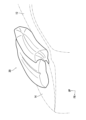
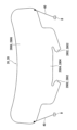
- FIG. 1 is a side cross-sectional view showing a state in which an airbag of the airbag device according to the first embodiment is inflated and deployed; 1 is a perspective view showing a state in which an airbag of the airbag device according to the first embodiment is inflated and deployed; 1 is a side cross-sectional view of an airbag device according to a first embodiment.
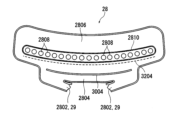
- FIG. 2 is a plan view of a base fabric for a first sub-chamber.
- FIG. 11 is a plan view of a base fabric for a second sub-chamber.
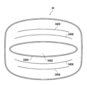
- FIG. 2 is a plan view of a main chamber base fabric.
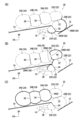
- 1A is a side cross-sectional view showing the first sub-chamber fabric portion of the inflated airbag, FIG.
- FIG. 1B is a side cross-sectional view showing the second sub-chamber fabric portion of the inflated airbag
- FIG. 1C is a side cross-sectional view showing the main chamber fabric of the inflated airbag.
- 13 is an explanatory diagram showing a state in which straps are connected to both ends of a sub-chamber in an airbag device according to a second embodiment.
- FIG. FIG. 11 is a side cross-sectional view of an airbag device according to a second embodiment.
- FIG. 11 is a side cross-sectional view showing a modified example of the second embodiment.
- the symbol FR indicates the front of the vehicle
- the symbol UP indicates the upper side of the vehicle.
- the airbag device 10 of this embodiment is provided below and in the vicinity of the rear end of a vehicle hood 14, and an airbag 20 is inflated and deployed between the lower end of the windshield glass 12 and the rear end of the hood 14 to cover the rear portion of the upper surface of the hood 14.
- the hood 14 is a front-opening type, and a portion of the hood 14 near the rear end is supported pivotally via a hinge (not shown), thereby allowing the front end of the hood 14 to be opened and closed.
- a pop-up device (not shown) is activated under the control of an airbag ECU (not shown), causing the rear end of the hood 14 to rise above the vehicle.
- a space S (gap) for the airbag 20 to inflate and deploy is formed between the rear end of the raised hood 14 and the lower end of the windshield glass 12, in other words, between the rear end of the raised hood 14 and a deck (deck garnish) (not shown) supporting the lower end of the windshield glass 12, and the airbag 20 inflates and deploys through this space S to the rear of the upper surface of the hood 14.
- the airbag device 10 of the present embodiment includes an airbag case 16, an inflator 18, and an airbag 20.
- the airbag case 16 is made up of an upper case 1602 and a lower case 1604, and the outer flanges of these cases 1602, 1604 are attached to an inner panel 1402 of the hood 14 via bolts and nuts B.
- reference numeral 1404 denotes an outer panel of the hood 14.
- An accommodation chamber 16A is provided inside the upper case 1602 and the lower case 1604, and an inflator 18 is accommodated in this accommodation chamber 16A, and also an airbag 20 in a folded state is accommodated therein.
- the lower case 1604 is provided with a lid portion 1608 which breaks along a tear line 1606 and swings downward when the airbag 20 is inflated.
- the lid portion 1608 swings downward, the storage chamber 16A is opened, and the airbag 20 inflates and deploys through this open portion.
- the inflator 18 is supported within the airbag case 16 via a bracket 19 , and is actuated by an actuation signal supplied from the airbag ECU to supply inflation gas into the airbag 20 .
- the airbag 20 includes a sub-chamber 22 and a main chamber 24 .
- the sub-chamber 22 is inflated and deployed from below the hood 14 toward the front windshield 12 toward the rear of the vehicle, and then inflated and deployed so as to stand upward while in contact with the front windshield 12, forming a roughly L-shape.
- the sub-chamber 22 expands and deploys from below the rear end of the hood 14 toward the rear and upward through the space S, thereby abutting against the lower part of the windshield glass 12 and expanding and deploying in a direction approximately perpendicular to the windshield glass 12.
- the sub-chamber 22 is configured to include a first sub-chamber 22A, a second sub-chamber 22B, and a third sub-chamber 22C.
- the first sub-chamber 22A, the second sub-chamber 22B and the third sub-chamber 22C are formed by sewing together two pieces of base fabric, a first sub-chamber base fabric 26 and a second sub-chamber base fabric 28.
- the first sub-chamber base fabric 26 has a pair of first connecting portions 2602 connected to the inflator 18, a first narrow portion 2604 extending between the base portions of the pair of first connecting portions 2602, and a first wide portion 2606 connected to the first narrow portion 2604.
- the second sub-chamber base fabric 28 has a pair of second connecting portions 2802 connected to the inflator 18, a second narrow portion 2804 extending between the base portions of the pair of second connecting portions 2802, and a second wide portion 2806 connected to the second narrow portion 2804.
- the second wide portion 2806 is provided with a plurality of sub-chamber side openings 2808 which allow the inflation gas to flow to the main chamber 24, and the periphery of each of these sub-chamber side openings 2808 is sewn to the main chamber 24 to form a main chamber seam 2810.
- the second wide portion 2806 constitutes the third internal tether 4646 shown in FIG. 7 (B), and the sub-chamber side flow opening 2808 constitutes the third vent hole 46 formed in the third internal tether 46.
- the outer periphery of the pair of first connection parts 2602 of the first sub-chamber base fabric 26 and the outer periphery of the pair of second connection parts 2802 of the second sub-chamber base fabric 28 are sewn together and connected to the inflator 18, and the pair of first connection parts 2602 and the pair of second connection parts 2802 form the inflation gas supply passage 29 (see Figure 1).
- the outer peripheries of the first narrow width portion 2604 of the first sub-chamber base fabric 26 and the second narrow width portion 2804 of the second sub-chamber base fabric 28 are sewn together, and the outer peripheries of the first wide width portion 2606 of the first sub-chamber base fabric 26 and the second wide width portion 2806 of the second sub-chamber base fabric 28 are sewn together.
- the end of the first narrow portion 2604 closer to the first wide portion 2606 and the end of the second narrow portion 2804 closer to the second wide portion 2806 are connected via a first internal tether 30 .
- reference numeral 3002 indicates the location where the first internal tether 30 is joined to the first narrow portion 2604
- reference numeral 3004 indicates the location where the first internal tether 30 is joined to the second narrow portion 2804. Therefore, as shown in Figures 4 and 5, the first internal tether 30 forms the first sub-chamber 22A shown in Figure 7 between the first narrow portion 2604 and the second narrow portion 2804 on the inflation gas supply path 29 side of the first internal tether 30. As shown in FIG.
- a first vent hole 42 that connects the first sub-chamber 22A and the second sub-chamber 22B is provided in the first internal tether 30, and this first vent hole 42 faces in the fore-and-aft direction of the vehicle.
- the vertical thickness of the first sub-chamber 22A is restricted to be equal to or smaller than the gap between the rear end of the hood 14 and the deck (not shown) located below the hood 14 when the airbag 20 is deployed.
- reference numeral 3202 indicates a location where the second internal tether 32 is joined to the first wide portion 2606
- reference numeral 3204 indicates a location where the second internal tether 32 is joined to the second wide portion 2806.
- the second sub-chamber 22B is formed by almost the majority of the first wide portion 2606, the portion of the second wide portion 2806 located between the point where the first internal tether 30 is joined and the point where the second internal tether 32 is joined, and the second internal tether 32.
- a third sub-chamber 22C is formed by the portion of the first wide portion 2606 between the portion of the first wide portion 2606 to which the second internal tether 32 is joined and the edge of the first wide portion 2606 opposite this portion, the portion of the second wide portion 2806 between the portion of the second wide portion 2806 to which the second internal tether 32 is joined and the edge of the second wide portion 2806, and the second internal tether 32.
- a second vent hole 44 that connects the second sub-chamber 22B and the third sub-chamber 22C is provided in the second internal tether 32, and this second vent hole 44 faces in the vertical direction.
- sub-chamber side flow opening 2808 (third vent hole 46) faces in the fore-and-aft direction of the vehicle so that the main chamber 24 expands and deploys forward on the hood 14 when the first, second, and third sub-chambers 22A, 22B, and 22C are inflated and deployed.
- the main chamber 24 inflates and deploys from the third sub-chamber 22C forward of the vehicle on the hood 14.
- the main chamber 24 inflates and deploys from the front surface of the upper part of the sub-chamber 22C forward so as to cover the upper surface of the hood 14.
- the main chamber 24 is configured to include a first main chamber 24A, a second main chamber 24B, and a third main chamber 24C. As shown in FIG. 6, the first main chamber 24A, the second main chamber 24B and the third main chamber 24C are formed by sewing together a single main chamber base fabric 34.
- the main chamber base fabric 34 has a substantially rectangular shape, and a main chamber side communication opening 3402 is formed in the center of the short side of the rectangle, extending substantially parallel to the long side of the rectangle.
- reference numeral 3404 indicates a portion at the edge of the main chamber side communication opening 3402 that is joined to the main chamber seam portion 2810 of the second sub-chamber base fabric 28 shown in FIG.
- reference numeral 3406 in FIG. 6 indicates the points where the fourth internal tethers 36 provided on both sides of the main chamber side flow opening 3402 are joined, and reference numeral 3408 indicates the points where the fifth internal tether 38 is joined.
- the main chamber base fabric 34 is folded in half along a center line passing through approximately the center of a pair of short sides, and the outer periphery is sewn together. As shown in FIG. 7 , the main chamber base fabric 34 is divided into a first main chamber 24A, a second main chamber 24B, and a third main chamber 24C by a fourth internal tether 36 and a fifth internal tether 38, and the first main chamber 24A and the third sub-chamber 22C are connected to the sub-chamber side flow opening 2808 via the main chamber side flow opening 3402.
- the pop-up device is activated by an activation signal supplied from the airbag ECU, causing the rear end of the hood 14 to rise above the vehicle, and a space S is formed between the rear end of the hood 14 and the lower end of the windshield glass 12.
- the inflator 18 is activated, the airbag 20 is inflated, and the lid portion 1608 swings downward to open the storage chamber 16A. The airbag 20 inflates and deploys through this open portion and the space S.
- the inflation gas flows through the inflation gas supply passage 29 to inflate and deploy the first sub-chamber 22A, the first vent hole 42, the second sub-chamber 22B, the second vent hole 44, and the third sub-chamber 22C. That is, the first sub-chamber 22A expands and deploys rearward beneath the hood 14, the second sub-chamber 22B expands and deploys rearward of the rear end of the hood 14 and abuts against the lower part of the front windshield 12, and the third sub-chamber 22C expands and deploys upward above the hood 14 and assumes an upright position in a direction perpendicular to the front windshield 12.
- the inflation gas is supplied to the first main chamber 24A, the second main chamber 24B, and the third main chamber 24C through the sub-chamber side flow opening 2808 (third vent hole 46) and the main chamber side flow opening 3402, causing the main chamber 24 to inflate and deploy forward on the hood 14.
- the sub-chamber 22 is inflated and deployed from below the hood 14 toward the front windshield 12 toward the rear of the vehicle, and then inflates and deploys so as to stand upward while in contact with the front windshield 12, forming a roughly L-shape, and the main chamber 24 inflates and deploys from the upper part of the sub-chamber 22 toward the front so as to cover the upper surface of the hood 14. Therefore, since the sub-chamber 22 abuts against the front windshield 12, the reaction force from the front windshield 12 can be utilized, which is advantageous in inflating and deploying the sub-chamber 22 in a desired direction, and further, is advantageous in inflating and deploying the main chamber 24 along the hood 14. Therefore, the airbag 20 can be deployed reliably and stably against the upper surface of the hood 14 , which is advantageous in improving the deployment performance of the airbag 20 against the upper surface of the hood 14 .
- the sub-chamber 22 comprises a first sub-chamber 22A that expands and deploys rearward below the hood 14, a second sub-chamber 22B that is connected to the rear of the first sub-chamber 22A and expands and deploys rearward from the rear end of the hood 14 to abut against the windshield 12, and a third sub-chamber 22C that is connected to the upper part of the second sub-chamber 22B and expands and deploys above the hood 14 to an upright state, and the main chamber 24 expands and deploys forward from the front surface of the third sub-chamber 22.
- the reaction force from the front windshield 12 can be utilized, which is advantageous for inflating and deploying the third sub-chamber 22C in the desired direction and is even more advantageous for inflating and deploying the main chamber 24 along the hood 14. Therefore, the airbag 20 can be deployed reliably and stably against the upper surface of the hood 14, which is more advantageous in improving the deployment performance of the airbag 20 against the upper surface of the hood 14.
- first vent hole 42 connecting the first sub-chamber 22A and the second sub-chamber 22B is connected in the fore-and-aft direction of the vehicle
- second vent hole 44 connecting the second sub-chamber 22B and the third sub-chamber 22C is connected in the up-and-down direction
- third vent hole 46 connecting the third sub-chamber 22C and the main chamber 24 is connected in the fore-and-aft direction of the vehicle.
- the inflow direction of the inflation gas supplied from the inflator 18 matches the direction in which the first sub-chamber 22A, the second sub-chamber 22B, and the third sub-chamber 22C inflate and deploy, this is advantageous for ensuring stable deployment of each sub-chamber 22A, 22B, and 22C, and is further advantageous for improving the deployment performance of the airbag 20 against the upper surface of the hood 14.
- the vertical thickness of the first sub-chamber 22A is restricted to be equal to or less than the gap between the rear end of the hood 14 and the deck located below the hood 14 when the airbag 20 is deployed, so the first sub-chamber 22A is less likely to interfere with the rear end of the hood 14 and the deck, which is advantageous for ensuring stable deployment of the sub-chamber 22 and improving the deployment performance of the airbag 20 against the upper surface of the hood 14.
- the rear end of the hood 14 is configured to be able to be raised above the vehicle by a pop-up device, and the airbag 20 is inflated and deployed from the gap between the rear end of the raised hood 14 and the deck, which is advantageous for ensuring stable deployment of the airbag 20 and for improving the deployment performance of the airbag 20 against the upper surface of the hood 14.
- a pair of straps 40 are provided on both sides of the outer periphery where the first large portion 2606 and the second large portion 2806 are joined, and on the vehicle body side, to restrict upward movement of both ends of the sub-chamber 22 in the vehicle width direction when the airbag 20 is inflated and deployed.
- one end of the strap 40 is attached to the inner panel 1402 of the hood 14 together with the airbag case 16 via a bolt B.
- one end of a strap 40 is attached to a bracket 41 provided inside the airbag case 16 via a screw (not shown).
- the vertical height on both sides of the outer periphery where the first large portion 2606 and the second large portion 2806 that constitute the second sub-chamber 22B are joined is restricted by a pair of straps 40, so that the airbag 20 can be deployed reliably and stably against the upper surface of the hood 14, which is more advantageous in improving the deployment performance of the airbag 20 against the upper surface of the hood 14.
- Airbag device 12 Front windshield 14 Hood 1402 Inner panel 1404 Outer panel 16 Airbag case 1602 Upper case 1604 Lower case 1606 Tear line 1608 Lid 18 Inflator 19 Bracket 20 Airbag 22 Sub-chamber 22A First sub-chamber 22B Second sub-chamber 22C Third sub-chamber 24 Main chamber 24A First main chamber 24B Second main chamber 24C Third main chamber 26 First sub-chamber base cloth 2602 First connection portion 2604 First narrow portion 2606 First wide portion 28 Second sub-chamber base cloth 2802 Second connection portion 2804 Second narrow portion 2806 Second wide portion 2808 Sub-chamber side flow opening 2810 Main chamber seam 29 Inflation gas supply passage 30 First internal tether 3002, 3004 Location 32 Second internal tether 3202, 3204 Location 34 Main chamber base fabric 3402 Sub-chamber side flow openings 3404, 3406, 3408 Location 36 Fourth internal tether 38 Fifth internal tether 40 Strap 41 Bracket 42 First vent hole 44 Second vent hole 46 Third vent hole S Space (gap)
Landscapes
- Engineering & Computer Science (AREA)
- Mechanical Engineering (AREA)
- Air Bags (AREA)
Abstract
フードの上面に対するエアバッグの展開性能の向上を図る上で有利なエアバッグ装置を提供する。 衝突検知時あるいは衝突予知検知時に、フード14の後端とフロントウインドシールド12の下端との間に空間Sが形成される。インフレータ18が作動し、第1サブチャンバー22Aがフード14の下方で後方に向かって膨張展開され、第2サブチャンバー22Bがフード14の後端より後方で膨張展開されフロントウインドシールド12の下部に当接され、第3サブチャンバー22Cはフード14より上方に膨張展開されてフロントウインドシールド12と直交する方向に起立状態となる。膨張用ガスは、第3ベントホール46を介して第1メインチャンバー24A、第2メインチャンバー24B、第3メインチャンバー24Cに供給され、フード14上でメインチャンバー24を前方に膨張展開する。
Description
本発明は、エアバッグ装置に関する。
歩行者や自転車や自動二輪を運転する人に対する保護を図る観点から、車両の衝突時に、ウインドシールドガラスの下端とフードの後端との間からエアバッグを膨張展開させてウインドシールドガラスの下部とAピラーの下部を覆うエアバッグ装置が提案されている(引用文献1)。
また、ウインドシールドガラスの下端とフードの後端との間からエアバッグを膨張展開させてフードの上面の後部を覆うようにしたエアバッグ装置も提案されている。
また、ウインドシールドガラスの下端とフードの後端との間からエアバッグを膨張展開させてフードの上面の後部を覆うようにしたエアバッグ装置も提案されている。
後者のエアバッグ装置では、フードの上面に対してエアバッグを確実に安定して展開させること、言い換えると、エアバッグの展開性能の向上を如何にして図るかが重要である。
本発明は前記事情に鑑み案出されたものであり、本発明は、フードの上面に対するエアバッグの展開性能の向上を図る上で有利なエアバッグ装置を提供することを目的とする。
本発明は前記事情に鑑み案出されたものであり、本発明は、フードの上面に対するエアバッグの展開性能の向上を図る上で有利なエアバッグ装置を提供することを目的とする。
上記目的を達成するために、本発明の一実施の形態は、車両のフードの後端近傍の下方に設けられ、前記フードの上面を覆うように膨張展開されるエアバッグを備えるエアバッグ装置であって、前記フードの下方からフロントウインドシールドに向かって車両後方へに膨張展開された後、前記フロントウインドシールドに当接された状態で上方に起立するよう膨張展開される略L字状のサブチャンバーと、前記サブチャンバーの上部から前方に向かって前記フードの上面を覆うように膨張展開するメインチャンバーと、を有することを特徴とする。
本発明の一実施の形態によれば、フードの上面に対してエアバッグを確実に安定して展開させることができ、フードの上面に対するエアバッグの展開性能の向上を図る上で有利となる。
(第1の実施の形態)
以下、本発明の実施の形態について説明する。
なお、以下の図面において、符号FRは車両前方を示し、符号UPは車両上方を示す。
図1、図2に示すように、本実施の形態のエアバッグ装置10は、車両のフード14の後端近傍の下方に設けられ、ウインドシールドガラス12の下端とフード14の後端との間からエアバッグ20を膨張展開させてフード14の上面の後部を覆うようにしたものである。
フード14は前開き式であり、フード14の後端寄りの箇所が不図示のヒンジを介して揺動可能に支持されることで、フード14の前端が開閉される。
一方、衝突検知時あるいは衝突予知検知時に、不図示のエアバッグECUによる制御により不図示のポップアップ装置が作動することで、フード14の後端は車両上方に上昇し、これにより上昇されたフード14の後端とウインドシールドガラス12の下端との間に、言い換えると、上昇されたフード14の後端とウインドシールドガラス12の下端を支持する不図示のデッキ(デッキガーニッシュ)との間に、エアバッグ20が膨出展開するための空間S(隙間)が形成され、この空間Sを介してエアバッグ20がフード14の上面の後部に膨張展開する。
以下、本発明の実施の形態について説明する。
なお、以下の図面において、符号FRは車両前方を示し、符号UPは車両上方を示す。
図1、図2に示すように、本実施の形態のエアバッグ装置10は、車両のフード14の後端近傍の下方に設けられ、ウインドシールドガラス12の下端とフード14の後端との間からエアバッグ20を膨張展開させてフード14の上面の後部を覆うようにしたものである。
フード14は前開き式であり、フード14の後端寄りの箇所が不図示のヒンジを介して揺動可能に支持されることで、フード14の前端が開閉される。
一方、衝突検知時あるいは衝突予知検知時に、不図示のエアバッグECUによる制御により不図示のポップアップ装置が作動することで、フード14の後端は車両上方に上昇し、これにより上昇されたフード14の後端とウインドシールドガラス12の下端との間に、言い換えると、上昇されたフード14の後端とウインドシールドガラス12の下端を支持する不図示のデッキ(デッキガーニッシュ)との間に、エアバッグ20が膨出展開するための空間S(隙間)が形成され、この空間Sを介してエアバッグ20がフード14の上面の後部に膨張展開する。
図3に示すように、本実施の形態のエアバッグ装置10は、エアバッグケース16と、インフレータ18と、エアバッグ20とを含んで構成されている。
エアバッグケース16は、上ケース1602と下ケース1604とからなり、それらケース1602、1604の外周のフランジがボルトナットBを介してフード14のインナパネル1402に取り付けられている。なお、図中符号1404はフード14のアウタパネルを示す。
上ケース1602と下ケース1604の内部に収容室16Aが設けられ、この収容室16Aにインフレータ18が収容され、また、折りたたまれた状態のエアバッグ20が収容されている。
下ケース1604には、エアバッグ20の膨張時にテアライン1606を介して破断し下方に揺動する蓋部1608が設けられ、蓋部1608が下方に揺動することで収容室16Aが開放され、この開放された部分を介してエアバッグ20が膨張展開する。
インフレータ18は、エアバッグケース16内でブラケット19を介して支持され、エアバッグECUから供給される作動信号により作動し、エアバッグ20内に膨張用ガスを供給する。
エアバッグケース16は、上ケース1602と下ケース1604とからなり、それらケース1602、1604の外周のフランジがボルトナットBを介してフード14のインナパネル1402に取り付けられている。なお、図中符号1404はフード14のアウタパネルを示す。
上ケース1602と下ケース1604の内部に収容室16Aが設けられ、この収容室16Aにインフレータ18が収容され、また、折りたたまれた状態のエアバッグ20が収容されている。
下ケース1604には、エアバッグ20の膨張時にテアライン1606を介して破断し下方に揺動する蓋部1608が設けられ、蓋部1608が下方に揺動することで収容室16Aが開放され、この開放された部分を介してエアバッグ20が膨張展開する。
インフレータ18は、エアバッグケース16内でブラケット19を介して支持され、エアバッグECUから供給される作動信号により作動し、エアバッグ20内に膨張用ガスを供給する。
図1に示すように、エアバッグ20は、サブチャンバー22とメインチャンバー24とを備えている。
サブチャンバー22は、フード14の下方からフロントウインドシールド12に向かって車両後方へに膨張展開された後、フロントウインドシールド12に当接された状態で上方に起立するよう膨張展開され略L字状を呈する。
言い換えると、サブチャンバー22は、空間Sを介してフード14の後端の下方から後方で上方に膨張展開することでウインドシールドガラス12の下部に当接しウインドシールドガラス12に対してほぼ直交する方向に膨張展開する。
図1、図7に示すように、サブチャンバー22は、第1サブチャンバー22Aと第2サブチャンバー22Bと第3サブチャンバー22Cとを含んで構成されている。
図4、図5に示すように、それら第1サブチャンバー22Aと第2サブチャンバー22Bと第3サブチャンバー22Cは、第1サブチャンバー用基布26と第2サブチャンバー用基布28との2枚の基布が縫い合わされることで構成されている。
第1サブチャンバー用基布26は、インフレータ18に接続される一対の第1接続部2602と、一対の第1接続部2602の基部間にわたって延在する第1小幅部2604と、第1小幅部2604に接続される第1大幅部2606とを備えている。
第2サブチャンバー用基布28は、インフレータ18に接続される一対の第2接続部2802と、一対の第2接続部2802の基部間にわたって延在する第2小幅部2804と、第2小幅部2804に接続される第2大幅部2806とを備えている。
第2大幅部2806には、メインチャンバー24への膨張用ガスを流通させる複数のサブチャンバー側流通開口2808が設けられ、それらサブチャンバー側流通開口2808の周囲がメインチャンバー24に縫い合わされるメインチャンバー用縫合部2810となっている。
本実施の形態では、第2大幅部2806は、図7(B)に示す第3内部テザー4646を構成し、サブチャンバー側流通開口2808は、上記第3内部テザー46に形成された第3ベントホール46を構成している。
サブチャンバー22は、フード14の下方からフロントウインドシールド12に向かって車両後方へに膨張展開された後、フロントウインドシールド12に当接された状態で上方に起立するよう膨張展開され略L字状を呈する。
言い換えると、サブチャンバー22は、空間Sを介してフード14の後端の下方から後方で上方に膨張展開することでウインドシールドガラス12の下部に当接しウインドシールドガラス12に対してほぼ直交する方向に膨張展開する。
図1、図7に示すように、サブチャンバー22は、第1サブチャンバー22Aと第2サブチャンバー22Bと第3サブチャンバー22Cとを含んで構成されている。
図4、図5に示すように、それら第1サブチャンバー22Aと第2サブチャンバー22Bと第3サブチャンバー22Cは、第1サブチャンバー用基布26と第2サブチャンバー用基布28との2枚の基布が縫い合わされることで構成されている。
第1サブチャンバー用基布26は、インフレータ18に接続される一対の第1接続部2602と、一対の第1接続部2602の基部間にわたって延在する第1小幅部2604と、第1小幅部2604に接続される第1大幅部2606とを備えている。
第2サブチャンバー用基布28は、インフレータ18に接続される一対の第2接続部2802と、一対の第2接続部2802の基部間にわたって延在する第2小幅部2804と、第2小幅部2804に接続される第2大幅部2806とを備えている。
第2大幅部2806には、メインチャンバー24への膨張用ガスを流通させる複数のサブチャンバー側流通開口2808が設けられ、それらサブチャンバー側流通開口2808の周囲がメインチャンバー24に縫い合わされるメインチャンバー用縫合部2810となっている。
本実施の形態では、第2大幅部2806は、図7(B)に示す第3内部テザー4646を構成し、サブチャンバー側流通開口2808は、上記第3内部テザー46に形成された第3ベントホール46を構成している。
第1サブチャンバー用基布26の一対の第1接続部2602の外周部と、第2サブチャンバー用基布28の一対の第2接続部2802の外周部とが縫い合わされてインフレータ18に接続され、それら一対の第1接続部2602と一対の第2接続部2802により膨張用ガス供給路29(図1参照)が形成されている。
図4、図5、図7に示すように、第1サブチャンバー用基布26の第1小幅部2604と、第2サブチャンバー用基布28の第2小幅部2804の外周部が縫い合わされ、第1サブチャンバー用基布26の第1大幅部2606と、第2サブチャンバー用基布28の第2大幅部2806の外周部が縫い合わされる。
第1小幅部2604の第1大幅部2606寄りの端部と、第2小幅部2804の第2大幅部2806寄りの端部とは、図7に示すように、第1内部テザー30を介して接続されている。
なお、図4、図5において符号3002は、第1内部テザー30が第1小幅部2604に接合される箇所を示し、符号3004は、第1内部テザー30が第2小幅部2804に接合される箇所を示している。
したがって第1内部テザー30により、図4、図5に示すように、第1内部テザー30よりも膨張用ガス供給路29側の第1小幅部2604の箇所と第2小幅部2804の箇所とで図7に示す第1サブチャンバー22Aが形成される。
図7(B)に示すように、本実施の形態では、第1内部テザー30に第1サブチャンバー22Aと第2サブチャンバー22Bとを連通する第1ベントホール42が設けられ、この第1ベントホール42は車両前後方向を向いている。
なお、第1サブチャンバー22Aは、上下方向の厚みがエアバッグ20の展開時のフード14の後端とフード14の下方に位置する上記不図示のデッキとの隙間の間隔以下に規制されている。
第1小幅部2604の第1大幅部2606寄りの端部と、第2小幅部2804の第2大幅部2806寄りの端部とは、図7に示すように、第1内部テザー30を介して接続されている。
なお、図4、図5において符号3002は、第1内部テザー30が第1小幅部2604に接合される箇所を示し、符号3004は、第1内部テザー30が第2小幅部2804に接合される箇所を示している。
したがって第1内部テザー30により、図4、図5に示すように、第1内部テザー30よりも膨張用ガス供給路29側の第1小幅部2604の箇所と第2小幅部2804の箇所とで図7に示す第1サブチャンバー22Aが形成される。
図7(B)に示すように、本実施の形態では、第1内部テザー30に第1サブチャンバー22Aと第2サブチャンバー22Bとを連通する第1ベントホール42が設けられ、この第1ベントホール42は車両前後方向を向いている。
なお、第1サブチャンバー22Aは、上下方向の厚みがエアバッグ20の展開時のフード14の後端とフード14の下方に位置する上記不図示のデッキとの隙間の間隔以下に規制されている。
また、図4、図5、図7に示すように、第1小幅部2604から離れた第1大幅部2606の端部と、第2小幅部2804側の第2大幅部2806の端部とは、第2内部テザー32を介して接続されている。
図4、図5において符号3202は、第2内部テザー32が第1大幅部2606に接合される箇所を示し、符号3204は、第2内部テザー32が第2大幅部2806に接合される箇所を示している。
したがって、図4、図5、図7に示すように、第1大幅部2606のほぼ大半の部分と、第1内部テザー30が接合された箇所と第2内部テザー32が接合された箇所との間に位置する第2大幅部2806の部分と、第2内部テザー32により第2サブチャンバー22Bが形成されている。
図4、図5において符号3202は、第2内部テザー32が第1大幅部2606に接合される箇所を示し、符号3204は、第2内部テザー32が第2大幅部2806に接合される箇所を示している。
したがって、図4、図5、図7に示すように、第1大幅部2606のほぼ大半の部分と、第1内部テザー30が接合された箇所と第2内部テザー32が接合された箇所との間に位置する第2大幅部2806の部分と、第2内部テザー32により第2サブチャンバー22Bが形成されている。
また、図4、図5、図7に示すように、第2内部テザー32が接合された第1大幅部2606の箇所とこの箇所に対向する第1大幅部2606の縁部との間の第1大幅部2606の箇所と、第2内部テザー32が接合された第2大幅部2806の箇所と第2大幅部2806の縁部との間の第2大幅部2806の箇所と、第2内部テザー32とにより第3サブチャンバー22Cが形成されている。
図7(B)に示すように、本実施の形態では、第2内部テザー32に第2サブチャンバー22Bと第3サブチャンバー22Cとを連通する第2ベントホール44が設けられ、この第2ベントホール44は上下方向を向いている。
なお、第1、第2、第3サブチャンバー22A、22B、22Cが膨張展開した状態で、メインチャンバー24がフード14上で前方に膨張展開するように、サブチャンバー側流通開口2808(第3ベントホール46)は車両前後方向を向いている。
図7(B)に示すように、本実施の形態では、第2内部テザー32に第2サブチャンバー22Bと第3サブチャンバー22Cとを連通する第2ベントホール44が設けられ、この第2ベントホール44は上下方向を向いている。
なお、第1、第2、第3サブチャンバー22A、22B、22Cが膨張展開した状態で、メインチャンバー24がフード14上で前方に膨張展開するように、サブチャンバー側流通開口2808(第3ベントホール46)は車両前後方向を向いている。
図1、図7に示すように、メインチャンバー24は、第3サブチャンバー22Cからフード14上で車両前方に膨張展開する。言い換えると、メインチャンバー24は、サブチャンバー22の上部の前面から前方に向かってフード14の上面を覆うように膨張展開する。
メインチャンバー24は、第1メインチャンバー24Aと第2メインチャンバー24Bと第3メインチャンバー24Cとを含んで構成されている。
図6に示すように、それら第1メインチャンバー24Aと第2メインチャンバー24Bと第3メインチャンバー24Cは、1枚のメインチャンバー用基布34が縫い合わされることにより形成されている。
メインチャンバー用基布34は、ほぼ長方形状を呈し、長方形の短辺の中央に長方形の長辺にほぼ平行して延在するメインチャンバー側流通開口3402が形成されている。
図6において符号3404は、メインチャンバー側流通開口3402の縁で図5に示す第2サブチャンバー用基布28のメインチャンバー用縫合部2810に接合される箇所を示している。
また、図6に示す符号3406は、メインチャンバー側流通開口3402の両側にはそれぞれ設けられた第4内部テザー36が接合される箇所、符号3408は、第5内部テザー38が接合される箇所を示している。
メインチャンバー用基布34は、一対の短辺のほぼ中央を通る中心線を境に二つ折りされた状態で外周部が縫い合わされ、図7に示すように、第4内部テザー36および第5内部テザー38により第1メインチャンバー24Aと第2メインチャンバー24Bと第3メインチャンバー24Cに仕切られ、第1メインチャンバー24Aと第3サブチャンバー22Cはメインチャンバー側流通開口3402を介してサブチャンバー側流通開口2808に連通している。
メインチャンバー24は、第1メインチャンバー24Aと第2メインチャンバー24Bと第3メインチャンバー24Cとを含んで構成されている。
図6に示すように、それら第1メインチャンバー24Aと第2メインチャンバー24Bと第3メインチャンバー24Cは、1枚のメインチャンバー用基布34が縫い合わされることにより形成されている。
メインチャンバー用基布34は、ほぼ長方形状を呈し、長方形の短辺の中央に長方形の長辺にほぼ平行して延在するメインチャンバー側流通開口3402が形成されている。
図6において符号3404は、メインチャンバー側流通開口3402の縁で図5に示す第2サブチャンバー用基布28のメインチャンバー用縫合部2810に接合される箇所を示している。
また、図6に示す符号3406は、メインチャンバー側流通開口3402の両側にはそれぞれ設けられた第4内部テザー36が接合される箇所、符号3408は、第5内部テザー38が接合される箇所を示している。
メインチャンバー用基布34は、一対の短辺のほぼ中央を通る中心線を境に二つ折りされた状態で外周部が縫い合わされ、図7に示すように、第4内部テザー36および第5内部テザー38により第1メインチャンバー24Aと第2メインチャンバー24Bと第3メインチャンバー24Cに仕切られ、第1メインチャンバー24Aと第3サブチャンバー22Cはメインチャンバー側流通開口3402を介してサブチャンバー側流通開口2808に連通している。
次に、エアバッグ装置10の動作を図1、図7を参照して説明する。
衝突検知時あるいは衝突予知検知時に、エアバッグECUから供給される作動信号によりポップアップ装置が作動することで、フード14の後端は、車両上方に上昇し、フード14の後端とウインドシールドガラス12の下端との間に空間Sが形成される。
また、インフレータ18が作動し、エアバッグ20が膨張し、蓋部1608が下方に揺動することで収容室16Aが開放され、この開放された部分と空間Sを介してエアバッグ20が膨張展開する。
まず、膨張用ガスが膨張用ガス供給路29を介して第1サブチャンバー22A、第1ベントホール42、第2サブチャンバー22B、第2ベントホール44、第3サブチャンバー22Cを膨張展開させる。
すなわち、第1サブチャンバー22Aがフード14の下方で後方に向かって膨張展開され、第2サブチャンバー22Bがフード14の後端より後方で膨張展開されフロントウインドシールド12の下部に当接され、第3サブチャンバー22Cはフード14より上方に膨張展開されてフロントウインドシールド12と直交する方向に起立状態となる。
また、膨張用ガスは、サブチャンバー側流通開口2808(第3ベントホール46)とメインチャンバー側流通開口3402を介して第1メインチャンバー24A、第2メインチャンバー24B、第3メインチャンバー24Cに供給され、フード14上でメインチャンバー24を前方に膨張展開する。
衝突検知時あるいは衝突予知検知時に、エアバッグECUから供給される作動信号によりポップアップ装置が作動することで、フード14の後端は、車両上方に上昇し、フード14の後端とウインドシールドガラス12の下端との間に空間Sが形成される。
また、インフレータ18が作動し、エアバッグ20が膨張し、蓋部1608が下方に揺動することで収容室16Aが開放され、この開放された部分と空間Sを介してエアバッグ20が膨張展開する。
まず、膨張用ガスが膨張用ガス供給路29を介して第1サブチャンバー22A、第1ベントホール42、第2サブチャンバー22B、第2ベントホール44、第3サブチャンバー22Cを膨張展開させる。
すなわち、第1サブチャンバー22Aがフード14の下方で後方に向かって膨張展開され、第2サブチャンバー22Bがフード14の後端より後方で膨張展開されフロントウインドシールド12の下部に当接され、第3サブチャンバー22Cはフード14より上方に膨張展開されてフロントウインドシールド12と直交する方向に起立状態となる。
また、膨張用ガスは、サブチャンバー側流通開口2808(第3ベントホール46)とメインチャンバー側流通開口3402を介して第1メインチャンバー24A、第2メインチャンバー24B、第3メインチャンバー24Cに供給され、フード14上でメインチャンバー24を前方に膨張展開する。
本実施の形態によれば、サブチャンバー22は、フード14の下方からフロントウインドシールド12に向かって車両後方へ膨張展開された後、フロントウインドシールド12に当接された状態で上方に起立するよう膨張展開され略L字状を呈し、メインチャンバー24は、サブチャンバー22の上部から前方に向かってフード14の上面を覆うように膨張展開する。
したがって、サブチャンバー22がフロントウインドシールド12に当接するので、このフロントウインドシールド12からの反力を利用でき、サブチャンバー22を所望の方向に膨張展開させる上で有利となり、さらに、メインチャンバー24をフード14上に沿わせて膨張展開させる上で有利となる。
そのため、フード14の上面に対してエアバッグ20を確実に安定して展開させることができ、フード14の上面に対するエアバッグ20の展開性能の向上を図る上で有利となる。
したがって、サブチャンバー22がフロントウインドシールド12に当接するので、このフロントウインドシールド12からの反力を利用でき、サブチャンバー22を所望の方向に膨張展開させる上で有利となり、さらに、メインチャンバー24をフード14上に沿わせて膨張展開させる上で有利となる。
そのため、フード14の上面に対してエアバッグ20を確実に安定して展開させることができ、フード14の上面に対するエアバッグ20の展開性能の向上を図る上で有利となる。
また、本実施の形態では、サブチャンバー22は、フード14の下方で後方に向かって膨張展開される第1サブチャンバー22Aと、第1サブチャンバー22Aの後部に接続され、フード14の後端より後方で膨張展開されてウインドシールド12に当接する第2サブチャンバー22Bと、第2サブチャンバー22Bの上部に接続されてフード14より上方に膨張展開されて起立状態となる第3サブチャンバー22Cとを備え、メインチャンバー24は第3サブチャンバー22の前面から前方に膨張展開する。
したがって、第2サブチャンバー22Bがフロントウインドシールド12に当接するので、このフロントウインドシールド12からの反力を利用でき、第3サブチャンバー22Cを所望の方向に膨張展開させる上で有利となり、メインチャンバー24をフード14上に沿わせて膨張展開させる上でより有利となる。
そのため、フード14の上面に対してエアバッグ20を確実に安定して展開させることができ、フード14の上面に対するエアバッグ20の展開性能の向上を図る上でより有利となる。
したがって、第2サブチャンバー22Bがフロントウインドシールド12に当接するので、このフロントウインドシールド12からの反力を利用でき、第3サブチャンバー22Cを所望の方向に膨張展開させる上で有利となり、メインチャンバー24をフード14上に沿わせて膨張展開させる上でより有利となる。
そのため、フード14の上面に対してエアバッグ20を確実に安定して展開させることができ、フード14の上面に対するエアバッグ20の展開性能の向上を図る上でより有利となる。
また、本実施の形態では、第1サブチャンバー22Aと第2サブチャンバー22Bとを連通する第1ベントホール42は、車両前後方向を向いて連通され、第2サブチャンバー22Bと第3サブチャンバー22Cとを連通する第2ベントホール44は、上下方向を向いて連通され、第3サブチャンバー22Cとメインチャンバー24とを連通する第3ベントホール46は、車両前後方向を向いて連通されている。
したがって、インフレータ18から供給される膨張用ガスの流入方向が、第1サブチャンバー22A、第2サブチャンバー22B、第3サブチャンバー22Cが膨張展開する方向と合致しているため、各サブチャンバー22A、22B、22Cを確実に安定して展開させる上で有利となり、フード14の上面に対するエアバッグ20の展開性能の向上を図る上でより有利となる。
したがって、インフレータ18から供給される膨張用ガスの流入方向が、第1サブチャンバー22A、第2サブチャンバー22B、第3サブチャンバー22Cが膨張展開する方向と合致しているため、各サブチャンバー22A、22B、22Cを確実に安定して展開させる上で有利となり、フード14の上面に対するエアバッグ20の展開性能の向上を図る上でより有利となる。
また、本実施の形態では、第1サブチャンバー22Aは、上下方向の厚みがエアバッグ20の展開時のフード14の後端とフード14の下方に位置するデッキとの隙間の間隔以下に規制されているので、第1サブチャンバー22Aがフード14の後端とデッキとに干渉しにくくなるため、サブチャンバー22を確実に安定して展開させる上で有利となり、フード14の上面に対するエアバッグ20の展開性能の向上を図る上でより有利となる。
また、本実施の形態では、フード14は、後端側がポップアップ装置で車両上方に上昇可能に構成されており、エアバッグ20は、上昇されたフード14の後端とデッキとの隙間から膨張展開されるので、エアバッグ20を確実に安定して展開させる上で有利となり、フード14の上面に対するエアバッグ20の展開性能の向上を図る上でより有利となる。
(第2の実施の形態)
次に図8、図9、図10を参照して第2の実施の形態について説明する。
第2の実施の形態では、図8に示すように、第1大幅部2606と第2大幅部2806とが接合された外周部の両側と、車体側とにわたり一対のストラップ40を設け、エアバッグ20の膨張展開時におけるサブチャンバー22の車幅方向両端の上方への移動を規制している。
図9に示す構造では、ストラップ40の一端は、ボルトBを介してエアバッグケース16と共にフード14のインナパネル1402に取り付けられている。
図10に示す構造では、ストラップ40の一端は、エアバッグケース16の内部に設けたブラケット41に不図示のネジを介して取り付けられている。
第2の実施の形態によれば、第1の実施の形態と同様な効果が奏される他、第2サブチャンバー22Bを構成する第1大幅部2606と第2大幅部2806とが接合された外周部の両側の上下方向の高さが一対のストラップ40により規制されるため、フード14の上面に対してエアバッグ20を確実に安定して展開させ、フード14の上面に対するエアバッグ20の展開性能の向上を図る上でより有利となる。
次に図8、図9、図10を参照して第2の実施の形態について説明する。
第2の実施の形態では、図8に示すように、第1大幅部2606と第2大幅部2806とが接合された外周部の両側と、車体側とにわたり一対のストラップ40を設け、エアバッグ20の膨張展開時におけるサブチャンバー22の車幅方向両端の上方への移動を規制している。
図9に示す構造では、ストラップ40の一端は、ボルトBを介してエアバッグケース16と共にフード14のインナパネル1402に取り付けられている。
図10に示す構造では、ストラップ40の一端は、エアバッグケース16の内部に設けたブラケット41に不図示のネジを介して取り付けられている。
第2の実施の形態によれば、第1の実施の形態と同様な効果が奏される他、第2サブチャンバー22Bを構成する第1大幅部2606と第2大幅部2806とが接合された外周部の両側の上下方向の高さが一対のストラップ40により規制されるため、フード14の上面に対してエアバッグ20を確実に安定して展開させ、フード14の上面に対するエアバッグ20の展開性能の向上を図る上でより有利となる。
10 エアバッグ装置
12 フロントウインドシールド
14 フード
1402 インナパネル
1404 アウタパネル
16 エアバッグケース
1602 上ケース
1604 下ケース
1606 テアライン
1608 蓋部
18 インフレータ
19 ブラケット
20 エアバッグ
22 サブチャンバー
22A 第1サブチャンバー
22B 第2サブチャンバー
22C 第3サブチャンバー
24 メインチャンバー
24A 第1メインチャンバー
24B 第2メインチャンバー
24C 第3メインチャンバー
26 第1サブチャンバー用基布
2602 第1接続部
2604 第1小幅部
2606 第1大幅部
28 第2サブチャンバー用基布
2802 第2接続部
2804 第2小幅部
2806 第2大幅部
2808 サブチャンバー側流通開口
2810 メインチャンバー用縫合部
29 膨張用ガス供給路
30 第1内部テザー
3002、3004 箇所
32 第2内部テザー
3202、3204 箇所
34 メインチャンバー用基布
3402 サブチャンバー側流通開口
3404、3406、3408 箇所
36 第4内部テザー
38 第5内部テザー
40 ストラップ
41 ブラケット
42 第1ベントホール
44 第2ベントホール
46 第3ベントホール
S 空間(隙間)
12 フロントウインドシールド
14 フード
1402 インナパネル
1404 アウタパネル
16 エアバッグケース
1602 上ケース
1604 下ケース
1606 テアライン
1608 蓋部
18 インフレータ
19 ブラケット
20 エアバッグ
22 サブチャンバー
22A 第1サブチャンバー
22B 第2サブチャンバー
22C 第3サブチャンバー
24 メインチャンバー
24A 第1メインチャンバー
24B 第2メインチャンバー
24C 第3メインチャンバー
26 第1サブチャンバー用基布
2602 第1接続部
2604 第1小幅部
2606 第1大幅部
28 第2サブチャンバー用基布
2802 第2接続部
2804 第2小幅部
2806 第2大幅部
2808 サブチャンバー側流通開口
2810 メインチャンバー用縫合部
29 膨張用ガス供給路
30 第1内部テザー
3002、3004 箇所
32 第2内部テザー
3202、3204 箇所
34 メインチャンバー用基布
3402 サブチャンバー側流通開口
3404、3406、3408 箇所
36 第4内部テザー
38 第5内部テザー
40 ストラップ
41 ブラケット
42 第1ベントホール
44 第2ベントホール
46 第3ベントホール
S 空間(隙間)
Claims (6)
- 車両のフードの後端近傍の下方に設けられ、前記フードの上面を覆うように膨張展開されるエアバッグを備えるエアバッグ装置であって、
前記フードの下方からフロントウインドシールドに向かって車両後方へ膨張展開された後、前記フロントウインドシールドに当接された状態で上方に起立するよう膨張展開される略L字状のサブチャンバーと、
前記サブチャンバーの上部から前方に向かって前記フードの上面を覆うように膨張展開するメインチャンバーと、を有する、
ことを特徴とするエアバッグ装置。 - 前記サブチャンバーは、インフレータに接続され、前記フードの下方で後方に向かって膨張展開される第1サブチャンバーと、前記第1サブチャンバーの後部に接続され、前記フードの後端より後方で膨張展開されて前記ウインドシールドに当接する第2サブチャンバーと、前記第2サブチャンバーの上部に接続されて前記フードより上方に膨張展開されて起立状態となる第3サブチャンバーとを備え、
前記メインチャンバーは前記第3サブチャンバーの前面から前方に膨張展開する、
ことを特徴とする請求項1記載のエアバッグ装置。 - 前記第1サブチャンバーと前記第2サブチャンバーとを連通する第1ベントホールは、車両前後方向を向いて連通され、
前記第2サブチャンバーと前記第3サブチャンバーとを連通する第2ベントホールは、上下方向を向いて連通され、
前記第3サブチャンバーと前記メインチャンバーとを連通する第3ベントホールは、車両前後方向を向いて連通される
ことを特徴とする請求項2記載のエアバッグ装置。 - 前記第1サブチャンバーは、上下方向の厚みが前記エアバッグ展開時の前記フードの後端と前記フードの下方に位置するデッキとの隙間の間隔以下に規制されている
ことを特徴とする請求項2又は3記載のエアバッグ装置。 - 前記フードは、後端側がポップアップ装置で車両上方に上昇可能に構成されており、
前記エアバッグは、上昇された前記フードの後端と前記デッキとの隙間から膨張展開されることを特徴とする請求項1から4の何れか一項に記載のエアバッグ装置。 - 前記サブチャンバーの車幅方向両端の上方への移動を規制するストラップを設けた、
ことを特徴とする請求項1から5の何れか一項に記載のエアバッグ装置。
Priority Applications (1)
| Application Number | Priority Date | Filing Date | Title |
|---|---|---|---|
| PCT/JP2023/013079 WO2024201862A1 (ja) | 2023-03-30 | 2023-03-30 | エアバッグ装置 |
Applications Claiming Priority (1)
| Application Number | Priority Date | Filing Date | Title |
|---|---|---|---|
| PCT/JP2023/013079 WO2024201862A1 (ja) | 2023-03-30 | 2023-03-30 | エアバッグ装置 |
Publications (1)
| Publication Number | Publication Date |
|---|---|
| WO2024201862A1 true WO2024201862A1 (ja) | 2024-10-03 |
Family
ID=92903671
Family Applications (1)
| Application Number | Title | Priority Date | Filing Date |
|---|---|---|---|
| PCT/JP2023/013079 Ceased WO2024201862A1 (ja) | 2023-03-30 | 2023-03-30 | エアバッグ装置 |
Country Status (1)
| Country | Link |
|---|---|
| WO (1) | WO2024201862A1 (ja) |
Citations (8)
| Publication number | Priority date | Publication date | Assignee | Title |
|---|---|---|---|---|
| JP2006044291A (ja) * | 2004-07-30 | 2006-02-16 | Toyoda Gosei Co Ltd | 歩行者保護装置 |
| JP2006159971A (ja) * | 2004-12-02 | 2006-06-22 | Honda Motor Co Ltd | 車両外置きエアバッグ装置 |
| JP2007153062A (ja) * | 2005-12-02 | 2007-06-21 | Toyoda Gosei Co Ltd | 歩行者用エアバッグ装置 |
| JP2007261510A (ja) * | 2006-03-29 | 2007-10-11 | Toyoda Gosei Co Ltd | 歩行者用エアバッグ装置 |
| WO2012102661A1 (en) * | 2011-01-26 | 2012-08-02 | Autoliv Development Ab | Pedestrian airbag arrangement |
| JP2020011712A (ja) * | 2018-07-05 | 2020-01-23 | オートリブ ディベロップメント エービー | 歩行者保護エアバッグ装置 |
| JP2022178261A (ja) * | 2021-05-19 | 2022-12-02 | 豊田合成株式会社 | 歩行者用エアバッグ装置 |
| US20220396234A1 (en) * | 2021-06-09 | 2022-12-15 | Toyoda Gosei Co., Ltd. | Airbag device |
-
2023
- 2023-03-30 WO PCT/JP2023/013079 patent/WO2024201862A1/ja not_active Ceased
Patent Citations (8)
| Publication number | Priority date | Publication date | Assignee | Title |
|---|---|---|---|---|
| JP2006044291A (ja) * | 2004-07-30 | 2006-02-16 | Toyoda Gosei Co Ltd | 歩行者保護装置 |
| JP2006159971A (ja) * | 2004-12-02 | 2006-06-22 | Honda Motor Co Ltd | 車両外置きエアバッグ装置 |
| JP2007153062A (ja) * | 2005-12-02 | 2007-06-21 | Toyoda Gosei Co Ltd | 歩行者用エアバッグ装置 |
| JP2007261510A (ja) * | 2006-03-29 | 2007-10-11 | Toyoda Gosei Co Ltd | 歩行者用エアバッグ装置 |
| WO2012102661A1 (en) * | 2011-01-26 | 2012-08-02 | Autoliv Development Ab | Pedestrian airbag arrangement |
| JP2020011712A (ja) * | 2018-07-05 | 2020-01-23 | オートリブ ディベロップメント エービー | 歩行者保護エアバッグ装置 |
| JP2022178261A (ja) * | 2021-05-19 | 2022-12-02 | 豊田合成株式会社 | 歩行者用エアバッグ装置 |
| US20220396234A1 (en) * | 2021-06-09 | 2022-12-15 | Toyoda Gosei Co., Ltd. | Airbag device |
Similar Documents
| Publication | Publication Date | Title |
|---|---|---|
| US8210566B2 (en) | Vehicle between-seat airbag apparatus | |
| JP4226259B2 (ja) | 小型車両用エアバッグ装置 | |
| US20050189741A1 (en) | Knee-bag and occupant leg protection apparatus | |
| JP4403913B2 (ja) | 歩行者用エアバッグ装置 | |
| JP2003011871A (ja) | 鞍乗型車両用エアバッグ装置 | |
| JP4129136B2 (ja) | 自動二輪車 | |
| US7988189B2 (en) | Air bag cover and air bag device | |
| JP6948392B2 (ja) | 鞍乗り型車両のエアバッグ装置 | |
| WO2007083423A1 (ja) | 座席シート装置 | |
| JP6941177B2 (ja) | 鞍乗り型車両のエアバッグ装置 | |
| JP6677064B2 (ja) | 歩行者用エアバッグ装置及び自動車 | |
| JPWO2018221180A1 (ja) | 鞍乗り型車両のエアバッグ装置 | |
| US8931800B2 (en) | Airbag device for front passenger's seat | |
| JP5989494B2 (ja) | エアバッグ及びエアバッグ装置 | |
| JP7557715B2 (ja) | 歩行者用エアバッグ装置 | |
| CN101346260B (zh) | 乘员腿部约束装置 | |
| WO2024201862A1 (ja) | エアバッグ装置 | |
| JPWO2018221179A1 (ja) | 鞍乗り型車両のエアバッグ装置 | |
| JP2003165402A (ja) | 外面展開型エアバッグ装置 | |
| CN119705336A (zh) | 气囊装置 | |
| JP5604353B2 (ja) | エアバッグ装置及びエアバッグカバー | |
| JP2023076851A (ja) | 車両用ニーエアバッグ装置 | |
| JP2021138297A (ja) | サイドエアバッグ装置 | |
| JP4661693B2 (ja) | 助手席用エアバッグ | |
| JP2024142853A (ja) | エアバッグ装置 |
Legal Events
| Date | Code | Title | Description |
|---|---|---|---|
| 121 | Ep: the epo has been informed by wipo that ep was designated in this application |
Ref document number: 23930500 Country of ref document: EP Kind code of ref document: A1 |
|
| NENP | Non-entry into the national phase |
Ref country code: DE |
|
| 122 | Ep: pct application non-entry in european phase |
Ref document number: 23930500 Country of ref document: EP Kind code of ref document: A1 |