WO2024201774A1 - レーザ装置、露光装置、及び電子デバイスの製造方法 - Google Patents
レーザ装置、露光装置、及び電子デバイスの製造方法 Download PDFInfo
- Publication number
- WO2024201774A1 WO2024201774A1 PCT/JP2023/012791 JP2023012791W WO2024201774A1 WO 2024201774 A1 WO2024201774 A1 WO 2024201774A1 JP 2023012791 W JP2023012791 W JP 2023012791W WO 2024201774 A1 WO2024201774 A1 WO 2024201774A1
- Authority
- WO
- WIPO (PCT)
- Prior art keywords
- laser
- value
- parameter value
- control processor
- burst
- Prior art date
- Legal status (The legal status is an assumption and is not a legal conclusion. Google has not performed a legal analysis and makes no representation as to the accuracy of the status listed.)
- Ceased
Links
Images

























Classifications
-
- H—ELECTRICITY
- H01—ELECTRIC ELEMENTS
- H01S—DEVICES USING THE PROCESS OF LIGHT AMPLIFICATION BY STIMULATED EMISSION OF RADIATION [LASER] TO AMPLIFY OR GENERATE LIGHT; DEVICES USING STIMULATED EMISSION OF ELECTROMAGNETIC RADIATION IN WAVE RANGES OTHER THAN OPTICAL
- H01S3/00—Lasers, i.e. devices using stimulated emission of electromagnetic radiation in the infrared, visible or ultraviolet wave range
- H01S3/10—Controlling the intensity, frequency, phase, polarisation or direction of the emitted radiation, e.g. switching, gating, modulating or demodulating
- H01S3/13—Stabilisation of laser output parameters, e.g. frequency or amplitude
- H01S3/136—Stabilisation of laser output parameters, e.g. frequency or amplitude by controlling devices placed within the cavity
-
- H—ELECTRICITY
- H01—ELECTRIC ELEMENTS
- H01S—DEVICES USING THE PROCESS OF LIGHT AMPLIFICATION BY STIMULATED EMISSION OF RADIATION [LASER] TO AMPLIFY OR GENERATE LIGHT; DEVICES USING STIMULATED EMISSION OF ELECTROMAGNETIC RADIATION IN WAVE RANGES OTHER THAN OPTICAL
- H01S3/00—Lasers, i.e. devices using stimulated emission of electromagnetic radiation in the infrared, visible or ultraviolet wave range
- H01S3/10—Controlling the intensity, frequency, phase, polarisation or direction of the emitted radiation, e.g. switching, gating, modulating or demodulating
- H01S3/10038—Amplitude control
-
- H—ELECTRICITY
- H01—ELECTRIC ELEMENTS
- H01S—DEVICES USING THE PROCESS OF LIGHT AMPLIFICATION BY STIMULATED EMISSION OF RADIATION [LASER] TO AMPLIFY OR GENERATE LIGHT; DEVICES USING STIMULATED EMISSION OF ELECTROMAGNETIC RADIATION IN WAVE RANGES OTHER THAN OPTICAL
- H01S3/00—Lasers, i.e. devices using stimulated emission of electromagnetic radiation in the infrared, visible or ultraviolet wave range
- H01S3/10—Controlling the intensity, frequency, phase, polarisation or direction of the emitted radiation, e.g. switching, gating, modulating or demodulating
- H01S3/10069—Memorized or pre-programmed characteristics, e.g. look-up table [LUT]
-
- H—ELECTRICITY
- H01—ELECTRIC ELEMENTS
- H01S—DEVICES USING THE PROCESS OF LIGHT AMPLIFICATION BY STIMULATED EMISSION OF RADIATION [LASER] TO AMPLIFY OR GENERATE LIGHT; DEVICES USING STIMULATED EMISSION OF ELECTROMAGNETIC RADIATION IN WAVE RANGES OTHER THAN OPTICAL
- H01S3/00—Lasers, i.e. devices using stimulated emission of electromagnetic radiation in the infrared, visible or ultraviolet wave range
- H01S3/10—Controlling the intensity, frequency, phase, polarisation or direction of the emitted radiation, e.g. switching, gating, modulating or demodulating
- H01S3/13—Stabilisation of laser output parameters, e.g. frequency or amplitude
- H01S3/131—Stabilisation of laser output parameters, e.g. frequency or amplitude by controlling the active medium, e.g. by controlling the processes or apparatus for excitation
- H01S3/134—Stabilisation of laser output parameters, e.g. frequency or amplitude by controlling the active medium, e.g. by controlling the processes or apparatus for excitation in gas lasers
-
- H—ELECTRICITY
- H01—ELECTRIC ELEMENTS
- H01S—DEVICES USING THE PROCESS OF LIGHT AMPLIFICATION BY STIMULATED EMISSION OF RADIATION [LASER] TO AMPLIFY OR GENERATE LIGHT; DEVICES USING STIMULATED EMISSION OF ELECTROMAGNETIC RADIATION IN WAVE RANGES OTHER THAN OPTICAL
- H01S3/00—Lasers, i.e. devices using stimulated emission of electromagnetic radiation in the infrared, visible or ultraviolet wave range
- H01S3/14—Lasers, i.e. devices using stimulated emission of electromagnetic radiation in the infrared, visible or ultraviolet wave range characterised by the material used as the active medium
- H01S3/22—Gases
- H01S3/223—Gases the active gas being polyatomic, i.e. containing two or more atoms
- H01S3/225—Gases the active gas being polyatomic, i.e. containing two or more atoms comprising an excimer or exciplex
-
- H—ELECTRICITY
- H01—ELECTRIC ELEMENTS
- H01S—DEVICES USING THE PROCESS OF LIGHT AMPLIFICATION BY STIMULATED EMISSION OF RADIATION [LASER] TO AMPLIFY OR GENERATE LIGHT; DEVICES USING STIMULATED EMISSION OF ELECTROMAGNETIC RADIATION IN WAVE RANGES OTHER THAN OPTICAL
- H01S3/00—Lasers, i.e. devices using stimulated emission of electromagnetic radiation in the infrared, visible or ultraviolet wave range
- H01S3/14—Lasers, i.e. devices using stimulated emission of electromagnetic radiation in the infrared, visible or ultraviolet wave range characterised by the material used as the active medium
- H01S3/22—Gases
- H01S3/223—Gases the active gas being polyatomic, i.e. containing two or more atoms
- H01S3/225—Gases the active gas being polyatomic, i.e. containing two or more atoms comprising an excimer or exciplex
- H01S3/2251—ArF, i.e. argon fluoride is comprised for lasing around 193 nm
-
- H—ELECTRICITY
- H01—ELECTRIC ELEMENTS
- H01S—DEVICES USING THE PROCESS OF LIGHT AMPLIFICATION BY STIMULATED EMISSION OF RADIATION [LASER] TO AMPLIFY OR GENERATE LIGHT; DEVICES USING STIMULATED EMISSION OF ELECTROMAGNETIC RADIATION IN WAVE RANGES OTHER THAN OPTICAL
- H01S3/00—Lasers, i.e. devices using stimulated emission of electromagnetic radiation in the infrared, visible or ultraviolet wave range
- H01S3/23—Arrangements of two or more lasers not provided for in groups H01S3/02 - H01S3/22, e.g. tandem arrangements of separate active media
- H01S3/2375—Hybrid lasers
Definitions
- This disclosure relates to a laser apparatus, an exposure apparatus, and a method for manufacturing an electronic device.
- gas laser devices used for exposure include KrF excimer laser devices that output laser light with a wavelength of approximately 248 nm, and ArF excimer laser devices that output laser light with a wavelength of approximately 193 nm.
- the spectral linewidth of the natural oscillation light of KrF excimer laser devices and ArF excimer laser devices is wide, at 350 to 400 pm. Therefore, if a projection lens is made of a material that transmits ultraviolet light, such as KrF and ArF laser light, chromatic aberration may occur. As a result, the resolution may decrease. Therefore, it is necessary to narrow the spectral linewidth of the laser light output from the gas laser device to a level where chromatic aberration can be ignored. For this reason, a line narrowing module (LNM) containing a narrowing element (such as an etalon or grating) may be provided inside the laser resonator of the gas laser device to narrow the spectral linewidth.
- LNM line narrowing module
- a gas laser device in which the spectral linewidth is narrowed is called a narrow-line gas laser device.
- a laser device includes a laser oscillator that generates a pulsed laser beam, an actuator that adjusts the laser beam parameters of the pulsed laser beam, and a laser control processor that corrects the operating parameter values of the actuator to reduce the difference between the measured value and the target value of the laser beam parameter based on a changing pattern of the pulse time interval of the pulsed laser beam that changes continuously within a burst of burst oscillation in response to a command from an exposure device, and controls the actuator.
- An exposure apparatus is an exposure apparatus connectable to a laser apparatus including a laser oscillator that generates pulsed laser light, an actuator that adjusts the laser light parameters of the pulsed laser light, and a laser control processor that controls the actuator, and is equipped with a projection optical system that forms an image on a wafer surface using the pulsed laser light output from the laser apparatus, and an exposure control processor that acquires measured values of the laser light parameters of the pulsed laser light, and corrects the operating parameter values of the actuator based on a changing pattern of the pulse time interval of the pulsed laser light that changes continuously within a burst of burst oscillation so that the difference between the measured value and a target value is reduced, and outputs the corrected operating parameter values to the laser apparatus.
- a method for manufacturing an electronic device includes generating pulsed laser light using a laser device including a laser oscillator that generates pulsed laser light, an actuator that adjusts laser light parameters of the pulsed laser light, and a laser control processor that corrects operating parameter values of the actuator so as to reduce differences between measured values and target values of the laser light parameters based on a changing pattern of the pulse time interval of the pulsed laser light that changes continuously within a burst of burst oscillation at the command of the exposure device, and controls the actuator, outputting the pulsed laser light to an exposure device, and exposing the pulsed laser light onto a photosensitive substrate in the exposure device to manufacture an electronic device.
- a method for manufacturing an electronic device includes generating pulsed laser light by a laser device including a laser oscillator that generates pulsed laser light, an actuator that adjusts laser light parameters of the pulsed laser light, and a laser control processor that controls the actuator, outputting the pulsed laser light to an exposure device including a projection optical system that forms an image on a wafer surface using the pulsed laser light output from the laser device, and an exposure control processor that obtains measured values of the laser light parameters, corrects the operating parameter values of the actuator based on a changing pattern of the pulse time interval of the pulsed laser light that changes continuously within a burst of burst oscillation so that the difference between the measured value and a target value is small, and outputs the corrected operating parameter values to the laser device, and exposing the pulsed laser light onto a photosensitive substrate in the exposure device to manufacture an electronic device.
- FIG. 1 shows a schematic configuration of an exposure system in a comparative example.
- FIG. 2 is a schematic diagram showing the configuration of a laser device according to a comparative example.
- FIG. 3 shows an example of a semiconductor wafer being exposed by an exposure system.
- FIG. 4 shows an example of a trigger signal sent to the power supply.
- FIG. 5, together with FIGS. 6 and 7, shows how the position of the scan field changes relative to the position of the pulsed laser beam.
- FIG. 6, together with FIGS. 5 and 7, shows how the position of the scan field changes with respect to the position of the pulsed laser beam.
- FIG. 5 and 6 shows how the position of the scan field changes with respect to the position of the pulsed laser beam.
- FIG. 8 illustrates a procedure for sequentially exposing multiple scan fields.
- FIG. 9 is a graph showing the change in workpiece table speed and repetition rate when exposing a scan field in a comparative example.
- FIG. 10 is a graph showing the change in workpiece table speed and repetition rate during exposure during acceleration.
- FIG. 11 is a graph showing changes in the measured values of the repetition rate and the laser light parameters in the comparative example.
- FIG. 12 is a graph showing the continuously changing repetition rate and the changes in the measured values of the laser light parameters.
- FIG. 13 is a graph of the measured values of the laser light parameters in the first embodiment.
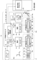
- FIG. 14 is a schematic diagram showing the configuration of the laser device according to the first embodiment.
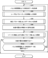
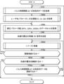
- FIG. 15 is a flowchart of laser control in the first embodiment.
- FIG. 16 is a flowchart showing a first example of a process for acquiring time series data of pulse time intervals.
- FIG. 17 is a flowchart showing a second example of the process for acquiring time series data of pulse time intervals.
- FIG. 18 shows an example of time series data of pulse time intervals.
- FIG. 19 is a flowchart illustrating an example of a process for obtaining target values of laser light parameters.
- FIG. 20 shows an example of target values of the laser light parameters.
- FIG. 21 is a flowchart showing a first example of a process for acquiring a data set of correction parameter values.
- FIG. 16 is a flowchart showing a first example of a process for acquiring time series data of pulse time intervals.
- FIG. 17 is a flowchart showing a second example of the process for acquiring time series data of pulse time intervals.
- FIG. 18 shows an example of time series data of pulse time
- FIG. 22 is a flowchart showing a second example of a process for acquiring a data set of correction parameter values.
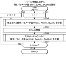
- FIG. 23 is a flowchart showing an example of a process for updating the correction parameter value while performing one burst oscillation.
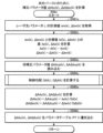
- FIG. 24 is a flow chart illustrating an example process for calculating corrected motion parameter values.
- FIG. 25 shows an example of a parameter table.
- FIG. 26 is a flowchart showing an example of a process for calculating an operation parameter value corresponding to a target value.
- FIG. 27 is a graph illustrating a method for calculating an operational parameter value from a relationship between the operational parameter value and the laser light parameter value.
- FIG. 28 is a flow chart illustrating an example process for calculating correction parameter values for a next burst.
- FIG. 29 is a flowchart illustrating an example of a process for calculating the control gradient.
- FIG. 30 is a graph illustrating how a control gradient is calculated from the relationship between the operating parameter value and the laser light parameter value.
- FIG. 31 is a flowchart of laser control in the first modified example of the first embodiment.
- FIG. 32 is a flowchart showing an example of a process for performing one burst oscillation.
- FIG. 33 is a flowchart illustrating an example of a process for acquiring a data set of correction parameter values in the second modified example of the first embodiment.
- FIG. 34 is a flowchart showing an example of a process of acquiring the relationship between the operation parameter value and the laser light parameter value in the second modified example of the first embodiment.
- FIG. 30 is a flowchart illustrating an example of a process for calculating the control gradient.
- FIG. 30 is a graph illustrating how a control gradient is calculated from the relationship between the operating parameter value and the laser light parameter value.
- FIG. 43 is a flow chart illustrating an example process for calculating corrected motion parameter values.
- FIG. 44 is a graph illustrating a method for calculating an operational parameter value from a relationship between the operational parameter value and the laser light parameter value.
- FIG. 45 is a graph illustrating a method for calculating an operational parameter value from a relationship between the operational parameter value and the laser light parameter value.
- FIG. 46 is a graph illustrating a method for calculating an operational parameter value from a relationship between the operational parameter value and the laser light parameter value.
- FIG. 47 is a flow chart illustrating an example process for calculating correction parameter values for a next burst.
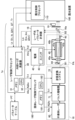
- FIG. 48 is a schematic diagram showing the configuration of a laser device according to the third embodiment.
- FIG. 49 is a flowchart of laser control in the third embodiment.
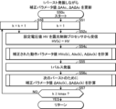
- FIG. 50 is a flowchart showing an example of a process for updating the correction parameter value while performing one burst oscillation.
- FIG. 51 is a flowchart illustrating an example of a process for calculating a corrected set voltage value and a corrected set value.
- FIG. 52 is a flow chart illustrating an example process for calculating correction parameter values for a next burst.
- FIG. 53 is a flowchart of laser control in a modified example of the third embodiment.
- FIG. 54 is a flowchart showing an example of a process for performing one burst oscillation.
- FIG. 55 is a schematic diagram showing the configuration of a laser device according to the fourth embodiment.
- Other elements including solid-state laser 9.1 Configuration 9.1.1 Laser oscillator 18 9.1.2 Laser Amplifier PA 9.2 Operation 10.
- Exposure apparatus 100a corrects operation parameter value A 10.1 Configuration 10.2 Operation 10.3 Function 11.
- FIG. 1 shows a schematic configuration of an exposure system in a comparative example.
- the comparative example of the present disclosure is a form that the applicant recognizes as being known only by the applicant, and is not a publicly known example that the applicant acknowledges.
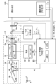
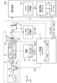
- the exposure system includes a laser device 1 and an exposure device 100.
- the laser device 1 includes a laser control processor 30.
- the laser control processor 30 is a processing device that includes a memory 31 in which a control program is stored, and a CPU (central processing unit) 32 that executes the control program.
- the laser control processor 30 is specially configured or programmed to execute various processes included in the present disclosure.
- the laser device 1 is configured to output a pulsed laser beam toward the exposure device 100.
- the exposure apparatus 100 includes an illumination optical system 101, a projection optical system 102, and an exposure control processor 110.
- the illumination optical system 101 illuminates a reticle pattern of a reticle (not shown) placed on a reticle stage RT with pulsed laser light incident from the laser device 1.
- the projection optical system 102 reduces and projects the pulsed laser light that has passed through the reticle, forming an image on a workpiece (not shown) placed on a workpiece table WT.
- the workpiece is a photosensitive substrate such as a semiconductor wafer coated with a resist film.
- the exposure control processor 110 is a processing device that includes a memory 111 in which a control program is stored, and a CPU 112 that executes the control program.
- the exposure control processor 110 is specially configured or programmed to execute the various processes included in this disclosure.
- the exposure control processor 110 manages the control of the exposure apparatus 100, and transmits and receives various data and signals to and from the laser control processor 30.
- Fig. 2 shows a schematic configuration of the laser apparatus 1 according to the comparative example.
- the laser apparatus 1 includes a laser oscillator 17, a power supply 12, a laser light parameter measuring instrument 16, a shutter 19, and a laser control processor 30.
- the laser apparatus 1 can be connected to an exposure apparatus 100.
- Fig. 2 shows a Z-axis, a V-axis, and an H-axis that are perpendicular to each other.
- a pulsed laser beam is output from the laser oscillator 17 in the Z direction.
- the laser oscillator 17 includes a laser chamber 10, a discharge electrode 11a, a line narrowing module 14, and a spectrum adjuster 15a.
- the line narrowing module 14 and the spectrum adjuster 15a form a laser resonator.
- the laser chamber 10 is disposed in the optical path of the laser resonator. Windows 10a and 10b are provided at both ends of the laser chamber 10.
- Discharge electrode 11a and a discharge electrode (not shown) that forms a pair with it are disposed inside the laser chamber 10.
- the discharge electrode (not shown) is positioned so as to overlap with the discharge electrode 11a in the direction of the V axis perpendicular to the paper surface.
- the laser chamber 10 is filled with a laser gas that includes, for example, argon gas or krypton gas as a rare gas, fluorine gas as a halogen gas, and neon gas as a buffer gas.
- the power source 12 includes a switch 13 and is connected to the discharge electrode 11a and a charger (not shown).
- the power source 12 is an example of an actuator in this disclosure.
- the line-narrowing module 14 includes multiple prisms 14a and 14b and a grating 14c.
- the prisms 14a and 14b are arranged in this order in the optical path of the light emitted from the window 10a.
- the surfaces of the prisms 14a and 14b where the light enters and exits are both parallel to the V direction.
- the grating 14c is Littrow-positioned in the optical path of the light that has passed through the prisms 14a and 14b so that the angle of incidence and the angle of diffraction are the same.
- the direction of the grooves of the grating 14c is parallel to the V direction.
- Rotation stage 14e includes a driver (not shown). Rotation stage 14e is an example of an actuator in this disclosure.
- the laser light parameter measuring instrument 16 includes an energy monitor and a spectrum monitor, not shown.
- the energy monitor includes a photodiode, not shown, and outputs a signal including a measured value Em of the pulse energy E of the pulse laser light.
- the spectrum monitor includes an etalon spectrometer, not shown, and outputs waveform data of the interference fringes of the pulse laser light.
- a processing device, not shown, included in the laser light parameter measuring instrument 16 calculates the measured values ⁇ m and ⁇ m of the wavelength ⁇ and spectral linewidth ⁇ of the pulse laser light from the waveform data of the interference fringes.
- the wavelength ⁇ of the pulse laser light means the central wavelength.
- the laser control processor 30 transmits the set value A ⁇ of the rotation angle of the prism 14b to the rotating stage 14e based on the target value ⁇ t of the wavelength ⁇ .
- the laser control processor 30 transmits the set value A ⁇ of the position of the cylindrical plano-concave lens 15c to the linear stage 15d based on the target value ⁇ t of the spectral line width ⁇ .
- the laser control processor 30 sends a trigger signal Tr to the power supply 12 .
- the switch 13 When the power supply 12 receives a trigger signal Tr, the switch 13 turns on. When the switch 13 turns on, the power supply 12 generates a pulsed high voltage according to a set voltage value HV from the electrical energy stored in a charger (not shown), and applies this high voltage to the discharge electrode 11a.
- the light emitted from the laser chamber 10 travels back and forth between the line narrowing module 14 and the spectrum adjuster 15a, and is amplified each time it passes through the discharge space inside the laser chamber 10. This light is narrowed in line each time it is turned back by the line narrowing module 14. The light thus oscillated and narrowed in line is output as pulsed laser light from the spectrum adjuster 15a.
- the linear stage 15d included in the spectral adjuster 15a moves the cylindrical plano-concave lens 15c along the optical path between the laser chamber 10 and the cylindrical plano-convex lens 15b according to the set value A ⁇ output from the laser control processor 30. This adjusts the wavefront of the light traveling from the spectral adjuster 15a to the line narrowing module 14, and adjusts the spectral linewidth ⁇ of the pulsed laser light.
- the laser light parameter measuring instrument 16 outputs the measured value Lm of the laser light parameter L of the pulsed laser light to the laser control processor 30.
- the measured value Em of the pulse energy E contained in the measured value Lm is used by the laser control processor 30 to feedback control the set voltage value HV.
- the measured value ⁇ m of the wavelength ⁇ contained in the measured value Lm is used by the laser control processor 30 to feedback control the set value A ⁇ of the rotation angle of the prism 14b.
- the measured value ⁇ m of the spectral linewidth ⁇ contained in the measured value Lm is used by the laser control processor 30 to feedback control the set value A ⁇ of the position of the cylindrical plano-concave lens 15c.
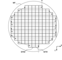
- FIG. 3 shows an example of a semiconductor wafer WF exposed by an exposure system.
- FIG. 3 shows an X-axis and a Y-axis that are orthogonal to each other in the plane of the semiconductor wafer WF.
- the semiconductor wafer WF is, for example, a plate of monocrystalline silicon having a substantially circular disk shape.
- a photosensitive resist film is applied to the semiconductor wafer WF.
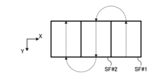
- the exposure of the semiconductor wafer WF is performed for each section of scan fields SF#1, SF#2, etc.
- Each of the scan fields SF#1, SF#2 corresponds to an area where a reticle pattern of one reticle is transferred.
- #1 and #2 indicate the order of exposure.
- the semiconductor wafer WF is moved so that the first scan field SF#1 is irradiated with pulsed laser light, and the scan field SF#1 is exposed. After that, the semiconductor wafer WF is moved so that the second scan field SF#2 is irradiated with pulsed laser light, and the scan field SF#2 is exposed. Thereafter, the semiconductor wafer WF is moved in the same manner to expose all the scan fields SF.
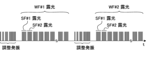
- Figure 4 shows an example of a trigger signal Tr sent to the power supply 12.
- a trigger signal Tr sent to the power supply 12.
- pulsed laser light is output continuously at a predetermined repetition frequency.
- the output of pulsed laser light is stopped.
- the operation of continuously outputting pulsed laser light is called a burst.
- bursts are repeated multiple times. This type of laser oscillation is called burst oscillation.
- the output of the pulsed laser light to the exposure device 100 is stopped in order to replace the semiconductor wafer WF#1 on the workpiece table WT with the second semiconductor wafer WF#2.
- adjustment oscillation may be performed for the purpose of adjusting parameters, etc.
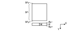
- Figures 5 to 7 show how the position of the scan field SF changes with respect to the position of the pulsed laser light.
- the width of the scan field SF in the X-axis direction is the same as the width of the beam cross section B of the pulsed laser light at the position of the workpiece table WT in the X-axis direction.
- the width of the scan field SF in the Y-axis direction is greater than the width W of the beam cross section B of the pulsed laser light at the position of the workpiece table WT in the Y-axis direction.
- the procedure for exposing the scan field SF with pulsed laser light is performed in the order of Figures 5, 6, and 7.
- the workpiece table WT is positioned so that the +Y end SFy+ of the scan field SF is located a predetermined distance in the -Y direction from the position of the -Y end By- of the beam cross section B.
- the workpiece table WT is accelerated in the +Y direction.
- the speed of the workpiece table WT becomes Vy.
- the scan field SF is exposed while moving the workpiece table WT so that the position of the scan field SF moves linearly at a constant speed Vy relative to the position of the beam cross section B.
- Vy the position of the scan field SF
- the exposure of the scan field SF is completed. In this way, exposure is performed while the scan field SF moves relative to the position of the beam cross section B.
- Figure 9 is a graph showing the change in speed V and repetition frequency f of the workpiece table WT when exposing the scan field SF in the comparative example.
- the scan field SF is exposed by pulsed laser light of repetition frequency f while the workpiece table WT moves in a uniform linear motion at speed Vy so that the number of irradiation pulses Ns is constant at every position in the scan field SF.
- acceleration from speed 0 is required, and after exposure, deceleration to speed 0 is required.
- exposure cannot be performed during the acceleration and deceleration period, which can hinder improvements in production efficiency.
- the repetition frequency f of the pulsed laser light during exposure is a constant value
- the repetition frequency f is changed during exposure in accordance with the change in the speed V of the workpiece table WT so that the number of irradiation pulses Ns is constant at any position in the scan field SF.
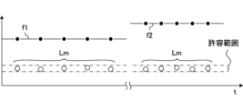
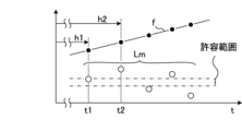
- FIG. 11 is a graph showing changes in the repetition frequency f and the measured value Lm of the laser light parameter L in the comparative example.
- the measured value Lm of the laser light parameter L may change due to changes in the influence of acoustic waves generated inside the laser chamber 10, changes in the influence of thermal loads on various optical elements, or other factors.
- the repetition frequency f changes, when the output of pulsed laser light at the same repetition frequency f is continuous as in the comparative example, it is possible to keep the measured value Lm within an allowable range by performing correction according to the repetition frequency f in addition to feedback control of the laser light parameter L. For example, a first correction may be performed at the first repetition frequency f1, and a second correction may be performed at the second repetition frequency f2.
- the change in the repetition frequency f shown in FIG. 12 corresponds to the change in the repetition frequency f during the period shown by XII in FIG. 10.
- correction according to the repetition frequency f is performed in addition to feedback control for each pulse.
- the measured value Lm will not be the same. It is presumed that the reason for this is that even if the repetition frequency f is the same, the density distribution and temperature distribution of the gas in the laser chamber 10 and the temperature of the optical element are different depending on the past history of the change in the repetition frequency f.
- the present disclosure aims to provide a laser device or a control method thereof that stabilizes the measured value Lm of the laser light parameter L to a value close to the target value Lt when the repetition frequency f is changed continuously.
- Laser device 1a using correction parameter value ⁇ Ac for each burst oscillation pulse 2.1
- Concept Fig. 13 is a graph of the measured value Lm of the laser light parameter L in the first embodiment.
- the repetition frequency f is smallest immediately after the start and immediately before the end of one burst, and the repetition frequency f gradually increases during the burst and then gradually decreases.
- the change pattern of the repetition frequency f is the same in the first burst and the second burst
- the history of change in the repetition frequency f is the same for pulses that are output in the same order in the first burst and the second burst.
- a correction parameter value ⁇ Ac of each pulse is calculated based on the difference between the measured value Lm of each pulse in the first burst and the target value Lt, and the correction parameter value ⁇ Ac is used to control the laser light parameter L of each pulse having the same output order in the second burst. This allows the measured value Lm of each pulse in the second burst to be closer to the target value Lt than the measured value Lm of each pulse in the first burst. Furthermore, by updating the correction parameter value ⁇ Ac while repeating the bursts, the accuracy of the correction parameter value ⁇ Ac can be improved.
- the correction parameter value ⁇ Ac includes any one of a correction parameter value ⁇ HVc for correcting the set voltage value HV, a correction parameter value ⁇ A ⁇ c for correcting the set value A ⁇ of the rotation angle of the prism 14b, and a correction parameter value ⁇ A ⁇ c for correcting the set value A ⁇ of the position of the cylindrical plano-concave lens 15c.
- the laser control processor 30 includes an internal trigger oscillator 33.
- the internal trigger oscillator 33 is configured to generate and transmit a trigger signal Tr to the power supply 12 without receiving a trigger signal Tr from the exposure control processor 110 when performing the adjusted oscillation described below.
- the exposure control processor 110 transmits time series data of the pulse time interval ⁇ T to the laser control processor 30.
- the time series data of the pulse time interval ⁇ T will be described later with reference to FIG. 18.
- the laser control processor 30 is configured to be able to access the parameter table PT.
- the parameter table PT stores the correction parameter value ⁇ Ac for each pulse in a burst.
- the parameter table PT corresponds to the table in this disclosure. The parameter table PT will be described further below with reference to FIG. 25.
- the laser control processor 30 corrects the operating parameter value A calculated based on the target value Lt using the correction parameter value ⁇ Ac, and transmits the corrected operating parameter value Ac to the corresponding actuator.
- the corrected operating parameter value Ac includes any one of the corrected set voltage value HVc, the corrected set value A ⁇ c of the rotation angle of the prism 14b, and the corrected set value A ⁇ c of the position of the cylindrical plano-concave lens 15c.
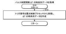
- the laser control processor 30 acquires time series data of the pulse time interval ⁇ T. Details of S10 will be described later with reference to Figures 16 to 18.
- the laser control processor 30 acquires the target value Lt of the laser light parameter L. Details of S20 will be described later with reference to Figures 19 and 20.
- the laser control processor 30 sends a preparation OK signal for exposure during acceleration to the exposure control processor 110.
- the exposure control processor 110 prepares the workpiece table WT and other parts for operation, and then sends various data and a trigger signal Tr to the laser control processor 30.
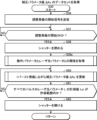
- the laser control processor 30 performs one burst oscillation using the correction parameter value ⁇ Ac while updating the correction parameter value ⁇ Ac for the next burst. Details of S50 will be described later with reference to Figures 23 to 30.
- the laser control processor 30 determines whether or not exposure during acceleration is to be continued. For example, if the exposure device 100 stops exposure during acceleration and performs exposure using uniform linear motion, it is determined that exposure during acceleration is not to be continued. If exposure during acceleration is not to be continued (S80: NO), the laser control processor 30 ends the processing of this flowchart. If exposure during acceleration is to be continued (S80: YES), the laser control processor 30 proceeds to S90.
- the laser control processor 30 determines whether or not to update the time series data of the pulse time interval ⁇ T. If the exposure apparatus 100 changes the change pattern of the pulse time interval ⁇ T, it is determined that the time series data of the pulse time interval ⁇ T is to be updated. If the time series data of the pulse time interval ⁇ T is to be updated (S90: YES), the laser control processor 30 returns the process to S10 to re-obtain an appropriate correction parameter value ⁇ Ac. If the time series data of the pulse time interval ⁇ T is not to be updated (S90: NO), the laser control processor 30 returns the process to S50.
- Fig. 16 is a flowchart showing a first example of a process for acquiring time series data of pulse time interval ⁇ T.
- Fig. 16 corresponds to a subroutine of S10 in Fig. 15.
- the laser control processor 30 acquires the time series data of the pulse time interval ⁇ T by receiving it from the exposure control processor 110.
- the laser control processor 30 ends the process of this flowchart and returns to the process shown in Fig. 15.
- FIG. 18 shows an example of time series data of pulse time interval ⁇ T.
- the number of pulses included in one burst is kmax. An integer value from 1 to kmax is assigned as the pulse number k in the burst according to the output order of the pulses.
- the pulse time interval ⁇ T is given for each pulse number k as the time difference from the previous pulse.
- the pulse time interval ⁇ T for a specific pulse number k is expressed as pulse time interval ⁇ T(k).
- pulse time interval ⁇ T(2) is the time interval from the output time of the pulse number 1 to the output time of the pulse number 2.
- the pulse time interval ⁇ T(1) may be, for example, the length of the pause period before the burst begins. Alternatively, the pulse time interval ⁇ T(1) may be blank.
- time series data of the repetition frequency f which is the inverse of the pulse time interval ⁇ T(k) may be acquired.
- Fig. 19 is a flowchart showing an example of processing for acquiring the target value Lt of the laser light parameter L.
- Fig. 19 corresponds to the subroutine of S20 in Fig. 15.
- the laser control processor 30 acquires the target value Lt by receiving it from the exposure control processor 110.
- the laser control processor 30 ends the processing of this flowchart and returns to the processing shown in Fig. 15.
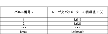
- FIG. 20 shows an example of a target value Lt of a laser light parameter L.
- the target value Lt may be set for each pulse number k and stored in association with the pulse number k.
- the target value Lt for a specific pulse number k is expressed as target value Lt(k).
- the target values Lt(1) to Lt(kmax) may all be the same value.
- Fig. 21 is a flowchart showing a first example of a process for acquiring a data set of the correction parameter value ⁇ Ac.
- Fig. 21 corresponds to the subroutine of S30 in Fig. 15.
- the laser apparatus 1a performs adjustment oscillation to acquire a data set of the correction parameter value ⁇ Ac.
- the laser control processor 30 transmits a start signal for adjusted oscillation to the exposure control processor 110. If it is OK to start adjusted oscillation in the laser device 1a, the exposure control processor 110 transmits a start OK signal to the laser control processor 30.
- the laser control processor 30 determines whether or not a start OK signal for adjusted oscillation has been received. If a start OK signal has not been received (S37: NO), the laser control processor 30 waits until a start OK signal is received. If a start OK signal has been received (S37: YES), the laser control processor 30 proceeds to S38.
- the laser control processor 30 closes the shutter 19.
- the shutter 19 does not need to be opened or closed.
- the laser control processor 30 opens the shutter 19. After S62, the laser control processor 30 ends the processing of this flowchart and returns to the processing shown in FIG. 15.
- FIG. 22 is a flow chart showing a second example of the process for acquiring a data set of the correction parameter value ⁇ Ac.
- FIG. 22 corresponds to the subroutine of S30 in FIG. 15.
- the correction parameter value ⁇ Ac is acquired from past log data (not shown) of the correction parameter value ⁇ Ac.
- the log data may be, for example, a parameter table PT as shown in FIG. 25 stored for each of a plurality of change patterns of the pulse time interval ⁇ T.
- the laser control processor 30 searches the log data for the correction parameter value ⁇ Ac.
- search keys the time series data for the pulse time interval ⁇ T, the data for the target value Lt of the laser light parameter L, and other data for the exposure conditions are used.
- the laser control processor 30 determines whether or not a data set of the correction parameter value ⁇ Ac that matches the search key exists. If a data set of the correction parameter value ⁇ Ac that matches the search key exists (S32: YES), the laser control processor 30 proceeds to S33. If a data set of the correction parameter value ⁇ Ac that matches the search key does not exist (S32: NO), the laser control processor 30 proceeds to S36 in FIG. 21, and then performs adjustment oscillation to obtain a data set of the correction parameter value ⁇ Ac.
- the laser control processor 30 reads a data set of the correction parameter values ⁇ Ac that match the search key from the log data. After S33, the laser control processor 30 ends the processing of this flowchart and returns to the processing shown in FIG. 15.
- the data set of the correction parameter values ⁇ Ac read in S33 may be used to control the pulsed laser light for performing exposure during acceleration.
- the laser control processor 30 may proceed to S36 in FIG. 21 and use the correction parameter value ⁇ Ac read in S33 as the initial value of the correction parameter value ⁇ Ac in the adjusted oscillation.
- the measured value Lm of the laser light parameter L can be brought into the allowable range early on, so that the number of bursts in the adjusted oscillation can be reduced and the reliability of the correction parameter value ⁇ Ac can be improved.
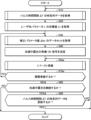
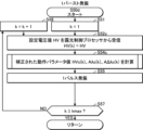
- Fig. 23 is a flow chart showing an example of a process for updating the correction parameter value ⁇ Ac while performing one burst oscillation.
- Fig. 23 shows a common process which corresponds to the subroutine of S50 in Fig. 15 and also corresponds to the subroutine of S50 in Fig. 21.
- S50 in Fig. 15 exposure during acceleration is performed after S40, whereas in S50 in Fig. 21, adjustment oscillation is performed after S38.
- the laser control processor 30 sets the value of the pulse number k to 1.
- the symbols indicating various values will be explained with (k) added to the end.
- the laser control processor 30 calculates a corrected operation parameter value Ac(k) by correcting the operation parameter value A(k) calculated based on the target value Lt(k) using the correction parameter value ⁇ Ac(k). Details of S54 will be described later with reference to Figures 24 to 27.
- the laser control processor 30 performs one pulse of laser oscillation to generate pulsed laser light.
- the process of FIG. 23 is performed as a subroutine of S50 in FIG. 15, the generated pulsed laser light is output to the exposure device 100.
- the process of FIG. 23 is performed as a subroutine of S50 in FIG. 21, the generated pulsed laser light does not have to be output to the exposure device 100.
- the processing of S55 is performed at a timing according to the pulse time interval ⁇ T(k). That is, the time difference between the pulse laser light of pulse number k-1 and pulse number k is the pulse time interval ⁇ T(k).
- the change pattern of the pulse time interval ⁇ T is the same when the processing of FIG. 23 is performed as a subroutine of S50 in FIG. 15 and when it is performed as a subroutine of S50 in FIG. 21. For this reason, the correction parameter value ⁇ Ac(k) obtained based on the change pattern of the pulse time interval ⁇ T in S50 in FIG. 21 can be used to correct the operating parameter value A(k) in S50 in FIG. 15.
- the laser control processor 30 calculates the correction parameter value ⁇ Ac(k) for the next burst so that the difference between the measured value Lm(k) of the laser light parameter L and the target value Lt(k) in the next burst is small. Details of S56 will be described later with reference to Figures 28 to 30.
- the laser control processor 30 determines whether the value of the pulse number k has reached the number of pulses kmax in one burst. If the value of the pulse number k has not reached the number of pulses kmax (S57: NO), the laser control processor 30 adds 1 to the value of the pulse number k in S58 to update the value of k, and returns to S54. If the value of the pulse number k has reached the number of pulses kmax (S57: YES), one burst has ended, so the laser control processor 30 ends the processing of this flowchart and returns to the processing shown in FIG. 15 or FIG. 21.
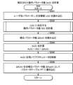
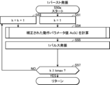
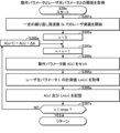
- Fig. 24 is a flowchart showing an example of a process for calculating the corrected operation parameter value Ac(k), which corresponds to the subroutine of S54 in Fig. 23.
- the laser control processor 30 controls the actuator using the corrected operating parameter value Ac(k). If the controlled laser light parameter L is the pulse energy E, the actuator is the power supply 12; if the controlled laser light parameter L is the wavelength ⁇ , the actuator is the rotary stage 14e; and if the controlled laser light parameter L is the spectral linewidth ⁇ , the actuator is the linear stage 15d. By starting control of the actuator before proceeding to S546, it is possible to complete the actuator drive early and make it in time for one-pulse laser oscillation in S55 (see FIG. 23).
- the laser control processor 30 writes the correction parameter value ⁇ Ac(k) into the parameter table PT as the old correction parameter value ⁇ Acp(k).
- the old correction parameter value ⁇ Acp(k) is the correction parameter value used in the laser oscillation, and is used to update the correction parameter value ⁇ Ac(k) in S56 (see FIG. 23).
- the laser control processor 30 ends the processing of this flowchart and returns to the processing shown in FIG. 23.
- FIG. 25 shows an example of the parameter table PT.
- the correction parameter value ⁇ Ac(k) is stored in association with the pulse number k of the pulse contained in one burst and the pulse time interval ⁇ T(k). Furthermore, the old correction parameter value ⁇ Acp(k) is stored in association with these. Furthermore, the target value Lt(k) of the laser light parameter L (see FIG. 20) may be stored in association with these.
- FIG. 26 is a flowchart showing an example of a process for calculating an operating parameter value A(k) corresponding to a target value Lt(k).
- FIG. 26 corresponds to the subroutine of S542 in FIG. 24.
- the laser control processor 30 reads the relationship between the operating parameter value A and the laser light parameter L.
- the relationship between the operating parameter value A and the laser light parameter L may be obtained by performing a separate adjustment oscillation, which will be described later with reference to Figures 33 to 36, and may be stored in the memory 31.
- the laser control processor 30 calculates the operation parameter value A(k) corresponding to the target value Lt(k) of the laser light parameter L based on the relationship between the operation parameter value A and the value of the laser light parameter L. After S5422, the laser control processor 30 ends the processing of this flowchart and returns to the processing shown in FIG. 24.
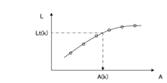
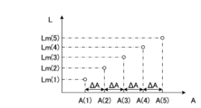
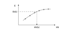
- FIG. 27 is a graph illustrating a method of calculating an operation parameter value A(k) from the relationship between the operation parameter value A and the value of the laser light parameter L.
- the relationship between the operation parameter value A and the value of the laser light parameter L may be represented by an approximation formula or by table data.
- the operation parameter value A(k) corresponding to the target value Lt(k) can be calculated from the approximation formula.
- the operation parameter value A(k) may be calculated by linear interpolation.
- FIG. 28 is a flowchart showing an example of a process for calculating a correction parameter value ⁇ Ac(k) for the next burst.
- Fig. 28 corresponds to the subroutine of S56 in Fig. 23.
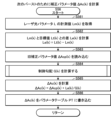
- the laser control processor 30 acquires the measured value Lm(k) of the laser light parameter L of the pulsed laser light generated in S55 (see FIG. 23) from the laser light parameter measuring device 16.
- the laser control processor 30 reads the old correction parameter value ⁇ Acp(k) from the parameter table PT.
- the laser control processor 30 calculates the control gradient G(k) corresponding to the operating parameter value A(k). Details of S564 will be described later with reference to Figures 29 and 30.
- the laser control processor 30 calculates the correction parameter value ⁇ Ac(k) by adding the value obtained by dividing the difference Le(k) by the control gradient G(k) and the previous correction parameter value ⁇ Acp(k).
- the laser control processor 30 writes the correction parameter value ⁇ Ac(k) calculated in S565 into the parameter table PT.
- the correction parameter value ⁇ Ac(k) is used to correct the operating parameter value A(k) in S54 (see FIG. 23) in the next burst.
- the laser control processor 30 ends the processing of this flowchart and returns to the processing shown in FIG. 23.
- the correction parameter value ⁇ Ac(k) for the next burst has been calculated before laser oscillation of the next pulse in the current burst (S55).
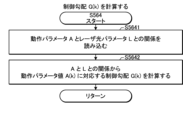
- FIG. 29 is a flowchart showing an example of a process for calculating the control gradient G(k).
- FIG. 29 corresponds to the subroutine of S564 in FIG. 28.
- the laser control processor 30 reads the relationship between the operating parameter value A and the value of the laser light parameter L.
- the relationship between the operating parameter value A and the value of the laser light parameter L may be the same as that read in FIG. 26.
- the laser control processor 30 calculates the control gradient G(k) corresponding to the operating parameter value A(k) based on the relationship between the operating parameter value A and the value of the laser light parameter L. After S5642, the laser control processor 30 ends the processing of this flowchart and returns to the processing shown in FIG. 28.
- FIG. 30 is a graph illustrating a method for calculating the control gradient G(k) from the relationship between the operation parameter value A and the value of the laser light parameter L.
- the relationship between the operation parameter value A and the value of the laser light parameter L is expressed by an approximate formula
- the differential value of the approximate formula at the operation parameter value A(k) may be used as the control gradient G(k).
- the control gradient G(k) may be calculated from the gradient between multiple measurement points close to the operation parameter value A(k).
- the laser apparatus 1a includes a laser oscillator 17 that generates a pulsed laser beam, actuators such as a power supply 12 that adjusts a laser beam parameter L of the pulsed laser beam, a rotation stage 14e, a linear stage 15d, and the like, and a laser control processor 30.
- the laser control processor 30 corrects an operating parameter value A of the actuator so as to reduce a difference Le between a measured value Lm and a target value Lt of the laser beam parameter L based on a changing pattern of a pulse time interval ⁇ T of the pulsed laser beam that changes continuously within a burst of burst oscillation in response to a command from the exposure apparatus 100, and controls the actuator.
- the pulse time interval ⁇ T changes continuously, it may not be possible to stabilize the measured value Lm near the target value Lt simply by making a correction corresponding to the pulse time interval ⁇ T.
- the difference Le between the measured value Lm and the target value Lt can be brought within an acceptable range.
- the laser control processor 30 calculates a correction parameter value ⁇ Ac for each pulse based on the difference Le between the measured value Lm and the target value Lt for each of multiple consecutive pulses in the first burst, and corrects the operating parameter value A calculated based on the target value Lt in the second burst that follows the first burst, based on the correction parameter value ⁇ Ac.
- the laser control processor 30 calculates the correction parameter value ⁇ Ac to be used in the second burst following the first burst while generating the pulsed laser light in the first burst.
- the correction parameter value ⁇ Ac is calculated based on the difference Le between the measured value Lm and the target value Lt in the first burst, so that the correction parameter value ⁇ Ac can be calculated early.
- the laser control processor 30 starts calculating the correction parameter value ⁇ Ac to be used in the second burst following the first burst before the second pulse of pulsed laser light following the first pulse is output.
- the laser control processor 30 calculates the correction parameter value ⁇ Ac based on the old correction parameter value ⁇ Acp for each pulse used in the first burst and the difference Le between the measured value Lm and the target value Lt for each pulse in the first burst.
- the old correction parameter value ⁇ Acp is used, which can improve the accuracy of the correction parameter value ⁇ Ac used in the next burst.
- the laser control processor 30 calculates the correction parameter value ⁇ Ac(k) by adding the value obtained by dividing the difference Le(k) by the control gradient G(k) calculated based on the operating parameter value A(k) to the previous correction parameter value ⁇ Acp(k).
- the laser control processor 30 is configured to be able to access a parameter table PT that stores the correction parameter value ⁇ Ac for each pulse in the change pattern, and corrects the operation parameter value A for each pulse calculated based on the target value Lt based on the correction parameter value ⁇ Ac.
- the laser control processor 30 is configured to be able to access a different parameter table PT for each change pattern, and determines the parameter table PT from which the correction parameter value ⁇ Ac is read based on the change pattern.
- the parameter table PT stores data on the pulse time interval ⁇ T and the correction parameter value ⁇ Ac for each pulse in association with each other.
- the parameter table PT includes a correction parameter value ⁇ Ac for each pulse included in one burst.
- the parameter table PT is configured to store the correction parameter value ⁇ Ac and the old correction parameter value ⁇ Acp that was previously used as the correction parameter value ⁇ Ac. After reading out the correction parameter value ⁇ Ac to correct the operation parameter value A, the laser control processor 30 stores it in the parameter table PT as the old correction parameter value ⁇ Acp, and updates the correction parameter value ⁇ Ac using the old correction parameter value ⁇ Acp and stores it in the parameter table PT.
- the laser control processor 30 performs a first adjusted oscillation to generate a pulsed laser beam based on the change pattern of the pulse time interval ⁇ T and the target value Lt of the laser beam parameter L, obtains a measured value Lm, and creates a parameter table PT by calculating a correction parameter value ⁇ Ac for each pulse based on the difference Le between the target value Lt and the measured value Lm for each pulse.
- the laser control processor 30 performs the process of performing the first adjustment oscillation to create the parameter table PT multiple times, and ends the first adjustment oscillation when the difference Le between the target value Lt and the measured value Lm falls within an allowable range.
- the accuracy of the correction parameter value ⁇ Ac can be improved by performing the adjustment oscillation multiple times, and an appropriate correction parameter value ⁇ Ac can be obtained by performing the adjustment oscillation until the difference Le falls within the allowable range.
- the first embodiment is similar to the comparative example.
- FIG. 31 is a flowchart of laser control in the first modified example of the first embodiment.
- the configuration of the first modified example is similar to that described with reference to Fig. 14.
- the processes of S50a and S70a are performed instead of S50 in Fig. 15.
- the laser control processor 30 performs one burst oscillation using the correction parameter value ⁇ Ac.
- the correction parameter value ⁇ Ac is not updated. Details of S50a will be described later with reference to FIG. 32.
- the laser control processor 30 determines whether or not to perform an adjusted oscillation. For example, when a sufficient downtime is expected, such as when replacing the semiconductor wafer WF or the reticle in the exposure apparatus 100, the laser control processor 30 determines to perform an adjusted oscillation. Alternatively, the laser control processor 30 may determine whether or not an adjusted oscillation start OK signal has been received from the exposure control processor 110, in which case S37 in FIG. 21 may be omitted. Alternatively, the laser control processor 30 may determine to perform an adjusted oscillation when the difference between the measured value Lm and the target value Lt of the laser light parameter L becomes larger than a threshold value. If an adjusted oscillation is to be performed (S70a: YES), the laser control processor 30 returns the process to S30. In S30, the process of S50 is performed as described with reference to FIG. 21, and the process of S50a is not performed. If an adjusted oscillation is not to be performed (S70a: NO), the laser control processor 30 advances the process to S80.
- Fig. 32 is a flowchart showing an example of processing for performing one burst oscillation.
- Fig. 32 corresponds to the subroutine of S50a in Fig. 31.
- Fig. 32 differs from Fig. 23 in that it does not include the processing of S56.
- the laser control processor 30 corrects the operating parameter value A using the same data set of the correction parameter value ⁇ Ac for the first burst and the second burst.
- the measured value Lm of the laser light parameter L can be kept within the allowable range without updating the correction parameter value ⁇ Ac during exposure. Furthermore, since the correction parameter value ⁇ Ac is not updated during exposure, the correction parameter value ⁇ Ac does not fluctuate and control can be stabilized.
- the first variant of the first embodiment is similar to the first embodiment.
- FIG. 33 is a flowchart showing an example of a process for acquiring a data set of the correction parameter value ⁇ Ac in the second modified example of the first embodiment.
- the configuration of the second modified example is similar to that described with reference to Fig. 14.
- S39e is added to perform the second adjustment oscillation.
- the laser control processor 30 performs a second adjustment oscillation to obtain the relationship between the operating parameter value A and the value of the laser light parameter L. Details of S39e are described below with reference to FIG. 34.
- Fig. 34 is a flowchart showing an example of a process for acquiring the relationship between the operation parameter value A and the value of the laser light parameter L in the second modified example of the first embodiment.
- Fig. 34 corresponds to the subroutine of S39e in Fig. 33.
- the laser control processor 30 starts laser oscillation at a constant repetition frequency fa.
- the laser control processor 30 may generate a trigger signal Tr of the repetition frequency fa by the internal trigger oscillator 33.
- the repetition frequency fa is set to a repetition frequency at which the laser light parameter L is not easily affected by acoustic waves, for example, 3 kHz or less, and is preferably set to 10 Hz or more and 1 kHz or less.
- FIG. 35 shows an example of the trigger signal Tr in the first and second adjusted oscillations.
- the trigger signal Tr in the first adjusted oscillation continuously changes the pulse time interval ⁇ T according to the change pattern of the pulse time interval ⁇ T.
- the maximum value of the pulse time interval ⁇ T is ⁇ Tmax.
- the pulse time interval in the second adjusted oscillation is constant at the reciprocal 1/fa of the repetition frequency fa, and 1/fa is longer than ⁇ Tmax.
- the laser control processor 30 sets the value of counter n, which counts the number of plots nmax of the operating parameter value A, to 0.
- the laser control processor 30 adds 1 to the value of counter n to update the value of n.
- the laser control processor 30 sets the operating parameter value A(n). For example, the first operating parameter value A(1) is set to the lower limit of the operating parameter value A.
- the actuator is controlled according to the set operating parameter value A(n), and a pulsed laser beam is generated.
- the laser control processor 30 acquires the measured value Lm(n) of the laser light parameter L of the generated pulsed laser light from the laser light parameter measuring device 16.
- the measured value Lm(n) may be an average value of the measured values Lm of multiple pulses of the pulsed laser light.
- the laser control processor 30 stores the operating parameter value A(n) and the measurement value Lm(n) in association with each other.
- the laser control processor 30 determines whether the value of the counter n has reached the number of plots nmax. If the value of the counter n has reached the number of plots nmax (S397e: YES), the laser control processor 30 ends the laser oscillation at the repetition frequency fa and ends the processing of this flowchart. If the value of the counter n has not reached the number of plots nmax (S397e: NO), the laser control processor 30 calculates the next operating parameter value A(n+1) by adding the step width ⁇ A to the current operating parameter value A(n), and then returns to the processing of S393e.
- FIG. 36 shows an example of the relationship between the operation parameter value A and the value of the laser light parameter L obtained by the second adjusted oscillation.
- the measured value Lm(n) is calculated for each operation parameter value A(n) and is associated with each other to obtain the relationship between the operation parameter value A and the value of the laser light parameter L.
- the laser control processor 30 performs a second adjusted oscillation to generate a pulsed laser beam while changing the operation parameter value A, obtains the relationship between the operation parameter value A and the measurement value Lm, and calculates either the operation parameter value A or the correction parameter value ⁇ Ac based on this relationship.
- the second adjustment oscillation is performed to obtain the relationship between the operating parameter value A and the value of the laser light parameter L, and the first adjustment oscillation is performed based on this relationship, so that the operating parameter value A(k) can be calculated with high accuracy in the first adjustment oscillation (see FIG. 27), or the control gradient G(k) can be calculated (see FIG. 30) to calculate the correction parameter value ⁇ Ac(k) with high accuracy.
- the characteristics of the laser device 1a can change due to changes in the gas composition inside the laser chamber 10, it is desirable to perform the second adjustment oscillation before the first adjustment oscillation each time the first adjustment oscillation is performed.
- the time interval 1/fa of the pulses in the second adjusted oscillation is longer than the longest time interval ⁇ Tmax among the time intervals of the pulses that change according to the change pattern in the first adjusted oscillation.
- the second modified example is similar to the first embodiment.
- the correction parameter value ⁇ Ac may not be updated during exposure, as in the first modified example.
- Fig. 37 is a flowchart of laser control in the second embodiment.
- the configuration of the second embodiment is similar to that described with reference to Fig. 14.
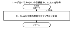
- target values Et, ⁇ t, and ⁇ t of the pulse energy E, wavelength ⁇ , and spectral linewidth ⁇ are obtained instead of the target value Lt of the laser light parameter L (S20b).
- a correction parameter value ⁇ HVc for correcting the set voltage value HV a correction parameter value ⁇ A ⁇ c for correcting the set value A ⁇ of the rotation angle of the prism 14b, and a correction parameter value ⁇ A ⁇ c for correcting the set value A ⁇ of the position of the cylindrical plano-concave lens 15c are obtained (S30b) and updated (S50b).
- FIG. 38 is a flowchart showing an example of a process for acquiring a target value Lt of the laser light parameter L.
- FIG. 39 shows an example of the target value Lt of the laser light parameter L.
- FIG. 40 is a flowchart showing an example of a process for acquiring a data set of the correction parameter value ⁇ Ac.
- FIG. 41 is a flowchart showing an example of a process for updating the correction parameter value ⁇ Ac while performing one burst oscillation.
- FIG. 42 shows an example of a parameter table PT.
- FIG. 43 is a flowchart showing an example of a process for calculating a corrected operation parameter value Ac(k).
- FIG. 44 to 46 are graphs illustrating a method for calculating the operation parameter value A(k) from the relationship between the operation parameter value A and the value of the laser light parameter L.
- FIG. 47 is a flowchart showing an example of a process for calculating the correction parameter value ⁇ Ac(k) for the next burst. These figures are similar to the corresponding figures in the first embodiment, except that the laser light parameter L is controlled in synchronization with each pulse of the pulsed laser light, that is, the pulse energy E, the wavelength ⁇ , and the spectral linewidth ⁇ .
- pulse energy E pulse energy E
- wavelength ⁇ wavelength ⁇
- spectral linewidth ⁇ can change in conjunction with each other; for example, after pulse energy E falls within the allowable range, changing the control of wavelength ⁇ and spectral linewidth ⁇ can change pulse energy E as well. As shown in FIG.
- the second embodiment is similar to the first embodiment.
- the correction parameter value ⁇ Ac may not be updated during exposure, as in the first modified example of the first embodiment, or a second adjustment oscillation may be performed, as in the second modified example of the first embodiment.
- Laser device 1c that receives the set voltage value HV from the exposure device 100 48 shows a schematic configuration of a laser apparatus 1c according to the third embodiment.
- the exposure apparatus 100 includes a pulse energy measuring instrument 116, which outputs a measured value Em2 of the pulse energy E to the exposure control processor 110.
- the exposure control processor 110 transmits a set voltage value HV for adjusting the pulse energy E to the laser control processor 30, instead of a target value Et of the pulse energy E.
- the laser control processor 30 performs one burst oscillation using the correction parameter values ⁇ HVc, ⁇ A ⁇ c, and ⁇ A ⁇ c, while updating the correction parameter values ⁇ A ⁇ c and ⁇ A ⁇ c for the next burst.
- the correction parameter value ⁇ HVc is not updated. This is because in the exposure apparatus 100, feedback control of the set voltage value HV for each pulse is performed based on the measured value Em2 of the pulse energy E, and updating the correction parameter value ⁇ HVc during exposure may cause the pulse energy E to become unstable. Details of S50c are described below with reference to FIG. 50.
- Fig. 50 is a flowchart showing an example of a process for updating the correction parameter value ⁇ Ac while performing one burst oscillation.
- Fig. 50 corresponds to a subroutine of S50c in Fig. 49.
- the processes of S52c and S54c are performed instead of S54b in Fig. 41, and the process of S56c is performed instead of S56b in Fig. 41.
- the laser control processor 30 receives the set voltage value HV from the exposure control processor 110.
- the laser control processor 30 stores the set voltage value HV in the memory 31 as the set voltage value HV(k) corresponding to the pulse number k.
- the laser control processor 30 calculates the corrected set voltage value HVc(k), the corrected set value A ⁇ c(k), and the corrected set value A ⁇ c(k) by correcting the set voltage value HV(k), the set value A ⁇ (k), and the set value A ⁇ (k). Details of S54c will be described later with reference to FIG. 51.
- the laser control processor 30 calculates the correction parameter values ⁇ A ⁇ c(k) and ⁇ A ⁇ c(k) for the next burst. Details of S56c will be described later with reference to FIG. 52.
- Fig. 51 is a flowchart showing an example of a process for calculating the corrected set voltage value HVc(k), the corrected set value A ⁇ c(k), and the corrected set value A ⁇ c(k).
- Fig. 51 corresponds to a subroutine of S54c in Fig. 50.
- the processes of S541c and S542c are performed instead of S541b and S542b in Fig. 43, and the process of S546c is performed instead of S546b in Fig. 43.
- the laser control processor 30 does not need to read the target value Et(k) of the pulse energy E, and does not need to calculate the set voltage value HV(k) corresponding to the target value Et(k) in S542c. This is because the set voltage value HV(k) has already been acquired in S52c (see FIG. 50).
- the target value Et of the pulse energy E is used in the adjustment oscillation (S30b in FIG. 49), but is not used during exposure (FIGS. 50 to 52), so it is sufficient to simply define a typical value in S20b in FIG. 49.
- the laser control processor 30 does not need to write the correction parameter value ⁇ HVc(k) as the old correction parameter value ⁇ HVcp(k) in the parameter table PT. This is because if the correction parameter value ⁇ HVc(k) is updated in parallel with the feedback control for each pulse in the exposure apparatus 100, the pulse energy E may become unstable.
- Fig. 52 is a flowchart showing an example of a process for calculating a correction parameter value ⁇ Ac(k) for the next burst.
- Fig. 52 corresponds to the subroutine of S56c in Fig. 50.
- the process for calculating the correction parameter value ⁇ HVc(k) based on the measured value Em(k) of the pulse energy E does not need to be performed.
- the laser light parameter L includes the pulse energy E.
- the laser control processor 30 receives the set voltage value HV for adjusting the pulse energy E from the exposure apparatus 100 as the operation parameter value A, and corrects the set voltage value HV using the same data set of the correction parameter value ⁇ Ac for the first burst and the second burst.
- the correction parameter value ⁇ HVc(k) is not updated during exposure, which prevents the pulse energy E from becoming unstable and enables highly accurate control based on the set voltage value HV set by the exposure apparatus 100.
- the third embodiment is similar to the second embodiment.
- the second adjustment oscillation may be performed in the same manner as in the second modification of the first embodiment.
- FIG. 53 is a flowchart of laser control in a modified example of the third embodiment.
- the configuration of the modified example is similar to that described with reference to Fig. 48.
- the processes of S50d and S70a are performed instead of S50c in Fig. 49.
- the laser control processor 30 performs one burst oscillation using the correction parameter value ⁇ Ac.
- the correction parameter value ⁇ Ac is not updated. Details of S50d will be described later with reference to FIG. 54.
- FIG. 54 is a flow chart showing an example of processing for performing one burst oscillation.
- FIG. 54 corresponds to the subroutine S50d in FIG. 53.
- FIG. 54 differs from FIG. 50 in that it does not include the processing of S56c.
- the variation of the third embodiment is similar to the third embodiment.
- a laser oscillator 17 includes an output coupling mirror 15 instead of a spectral adjuster 15a.
- One surface of the output coupling mirror 15 is coated with a partially reflective film.
- the output coupling mirror 15 does not need to have a function of adjusting the spectral linewidth ⁇ .
- the laser device 1d includes a laser amplifier PO between the laser oscillator 17 and the beam splitter 16a.
- the laser amplifier PO includes a laser chamber 20, discharge electrodes 21a and 21b, a rear mirror 24, and an output coupling mirror 25.
- the rear mirror 24 is made of a material that transmits pulsed laser light, and one surface of the rear mirror 24 is coated with a partially reflective film. The reflectance of the rear mirror 24 is set higher than the reflectance of the output coupling mirror 25.
- the laser chamber 20 is disposed in the optical path of the laser resonator that is composed of the rear mirror 24 and the output coupling mirror 25. Windows 20a and 20b are provided at both ends of the laser chamber 20.
- Discharge electrodes 21a and 21b are disposed inside the laser chamber 20.
- a power supply 22 is connected to the discharge electrode 21a, and the power supply 22 is connected to a charger (not shown).
- the power supply 22 includes a switch 23.
- the above-mentioned components of the laser amplifier PO are similar to the corresponding components of the laser oscillator 17.
- an example of a Fabry-Perot type resonator has been shown as the optical resonator of the laser amplifier PO, the optical resonator is not limited to this example, and may be a ring resonator.
- the laser control processor 30 sets a target value Et1 of the pulse energy E1 of the pulsed laser beam B1 output from the laser oscillator 17.
- the laser control processor 30 further receives from the exposure control processor 110 the target values Et, ⁇ t, and ⁇ t of the pulse energy E, wavelength ⁇ , and spectral linewidth ⁇ , the pulse time interval ⁇ T, and a trigger signal Tr of the pulsed laser beam B2 output from the laser amplifier PO.
- the laser control processor 30 transmits set voltage values HV1 and HVc to the power supplies 12 and 22, respectively, based on the target values Et1 and Et.
- the laser control processor 30 transmits first and second trigger signals Tr1 and Tr2 to the power supplies 12 and 22, respectively, based on the trigger signal Tr.
- the switch 23 included in the power supply 22 turns on when it receives a second trigger signal Tr2 from the laser control processor 30.
- Tr2 a second trigger signal from the laser control processor 30.
- the power supply 22 generates a pulsed high voltage from the electrical energy stored in a charger (not shown) and applies this high voltage to the discharge electrode 21a.
- the timing of the second trigger signal Tr2 to the switch 23 relative to the timing of the first trigger signal Tr1 to the switch 13 is controlled so that the second discharge timing at which a discharge occurs inside the laser chamber 20 is synchronized with the first discharge timing at which a discharge occurs inside the laser chamber 10 by a delay time ⁇ T.
- Pulse laser light B1 generated by the discharge in the laser chamber 10 and entering the laser chamber 20 travels back and forth between the rear mirror 24 and the output coupling mirror 25, and is amplified each time it passes through the discharge space inside the laser chamber 20.
- the amplified pulse laser light B2 is output from the output coupling mirror 25.
- FIG. 56 is a graph showing the relationship between the delay time ⁇ T of the second discharge timing relative to the first discharge timing and the spectral linewidth ⁇ of the pulsed laser light B2 output from the laser amplifier PO.
- the delay time ⁇ T becomes shorter, the spectral linewidth ⁇ becomes larger, and as the delay time ⁇ T becomes longer, the spectral linewidth ⁇ becomes smaller.
- the spectral linewidth ⁇ can be adjusted by the delay time ⁇ T.
- a delay circuit (not shown) for adjusting the delay time ⁇ T is an example of an actuator in this disclosure.
- the laser control processor 30 corrects the set value A ⁇ of the delay time ⁇ T calculated from the target value ⁇ t of the spectral linewidth ⁇ received from the exposure control processor 110 based on the correction parameter value ⁇ A ⁇ c, and sets the delay time ⁇ T by calculating the corrected set value A ⁇ c. This makes it possible to appropriately control the spectral linewidth ⁇ of the pulsed laser light B2 even when the pulse time interval ⁇ T changes continuously within a burst.
- the laser control processor 30 calculates the correction parameter value ⁇ A ⁇ c for the next burst based on the difference between the measured value ⁇ m of the spectral linewidth ⁇ and the target value ⁇ t, and stores it in the parameter table PT.
- a spectral adjuster 15a may be disposed at the position of the output coupling mirror 15, and the spectral linewidth ⁇ may be adjusted by the spectral adjuster 15a.
- the laser control processor 30 corrects the set voltage value HV calculated from the target value Et of the pulse energy E received from the exposure control processor 110 based on the correction parameter value ⁇ HVc, calculates the corrected set voltage value HVc, and controls the power supply 22. This makes it possible to appropriately control the pulse energy E of the pulse laser light B2 even when the pulse time interval ⁇ T changes continuously within a burst.
- the laser control processor 30 calculates the correction parameter value ⁇ HVc for the next burst based on the difference between the measured value Em of the pulse energy E and the target value Et, and stores it in the parameter table PT.
- the fourth embodiment is similar to the first embodiment.
- the correction parameter value ⁇ Ac may not be updated during exposure, as in the first modified example of the first embodiment, or a second adjustment oscillation may be performed, as in the second modified example of the first embodiment.
- the pulse energy E, the wavelength ⁇ , and the spectral linewidth ⁇ may be synchronously controlled, as in the second embodiment.
- the set voltage value HV received from the exposure apparatus 100 may be used, as in the third embodiment.
- Laser device 1e including a solid-state laser 57 is a schematic diagram showing the configuration of a laser device 1e according to the fifth embodiment.
- the laser device 1e includes a laser oscillator 18, a solid-state laser control processor 180, and a laser amplifier PA.
- the laser oscillator 18 includes a solid-state laser
- the laser amplifier PA includes a laser chamber that contains an excimer laser gas.
- the solid-state laser control processor 180 is a processing device including a memory 181 in which a control program is stored, and a CPU 182 that executes the control program.
- the solid-state laser control processor 180 is specially configured or programmed to execute various processes included in the present disclosure.
- the laser oscillator 18 includes a semiconductor laser 60, a pulse amplifier 71, and a wavelength conversion system 72.
- the semiconductor laser 60 includes a distributed feedback semiconductor laser, not shown.
- the distributed feedback semiconductor laser includes a semiconductor laser element, a Peltier element, and a function generator, not shown. Each of the Peltier element and the function generator is an example of an actuator in this disclosure.
- the pulse amplifier 71 includes a titanium sapphire crystal and a pumping pulse laser, not shown.
- the titanium sapphire crystal is disposed in the optical path of the CW laser light output from the semiconductor laser 60.
- the wavelength conversion system 72 includes an LBO (lithium triborate) crystal and a KBBF (potassium beryllium fluoroborate) crystal, not shown.
- the laser amplifier PA includes a laser chamber 40, discharge electrodes 41a and 41b, a concave mirror 44, and a convex mirror 45.
- the laser chamber 40 contains argon gas as a rare gas. Windows 40a and 40b are provided at both ends of the laser chamber 40.
- Discharge electrodes 41a and 41b are disposed inside the laser chamber 40.
- a power supply 42 is connected to the discharge electrode 41a, and the power supply 42 is connected to a charger (not shown).
- the power supply 42 includes a switch 43.
- the power supply 42 is an example of an actuator in this disclosure.
- the convex mirror 45 is disposed in the optical path of the pulsed laser light B1 that is output from the laser oscillator 18 and passes through the windows 40a and 40b of the laser chamber 40.
- the concave mirror 44 is disposed in the optical path of the pulsed laser light B1 that is reflected by the convex mirror 45 and passes through the windows 40a and 40b of the laser chamber 40 again.
- the focal points of the convex mirror 45 and the concave mirror 44 coincide with each other.
- a laser amplifier PA has been shown as an amplifier included in the laser device 1e, the amplifier is not limited to this example and may be, for example, a laser amplifier PO that includes a ring resonator.
- the laser control processor 30 receives the pulse energy E, wavelength ⁇ , and target values Et, ⁇ t, and ⁇ t of the spectral linewidth ⁇ of the pulsed laser light B2, the pulse time interval ⁇ T, and the trigger signal Tr from the exposure control processor 110.
- the laser control processor 30 transmits a set voltage value HVc to the power supply 42 based on the target value Et, and transmits set values A ⁇ c and A ⁇ c to the solid-state laser control processor 180 based on the target values ⁇ t and ⁇ t.
- the laser control processor 30 transmits first and second trigger signals Tr1 and Tr2 based on the trigger signal Tr to the solid-state laser control processor 180 and the power supply 42, respectively.
- the solid-state laser control processor 180 transmits the set values A ⁇ c and A ⁇ c to the semiconductor laser 60, and transmits the first trigger signal Tr1 to the pulse amplifier 71.
- the semiconductor laser element outputs a CW (continuous wave) laser light with a wavelength of approximately 773.6 nm.
- the central wavelength of the CW laser light output from the semiconductor laser element is adjusted by adjusting the temperature of the semiconductor laser element to a set value A ⁇ c using a Peltier element.
- the central wavelength of the CW laser light is chirped by increasing or decreasing the current supplied to the semiconductor laser element at a high frequency using a function generator.
- the larger the amplitude of the increasing or decreasing current the larger the spectral linewidth of the integrated spectral waveform obtained by integrating the spectral waveform of the CW laser light within the range of the pulse time width of the pulse laser light emitted from the pulse amplifier 71.
- the spectral linewidth is adjusted by adjusting the amplitude of the increasing or decreasing current to a set value A ⁇ c.
- the titanium sapphire crystal is excited by the pumping laser light output from the pumping pulse laser.
- the titanium sapphire crystal amplifies the CW laser light that is incident during the excited period into a pulsed form, and emits the pulsed laser light toward the wavelength conversion system 72.
- the wavelength conversion system 72 emits the fourth harmonic of the pulsed laser light output from the pulse amplifier 71 as pulsed laser light B1.
- the wavelength ⁇ of the pulsed laser light B1 is approximately 193.4 nm, which is the amplification wavelength of the ArF excimer that constitutes the laser amplifier PA. If the laser amplifier PA is composed of a KrF excimer, the configuration of the semiconductor laser 60 and the wavelength conversion system 72 is selected so as to output pulsed laser light B1 according to the amplification wavelength.
- a high voltage is applied to the discharge electrodes 41a and 41b so that discharge begins in the discharge space within the laser chamber 40 in synchronization with the timing at which the pulsed laser light B1 is incident on the laser chamber 40 from the laser oscillator 18.
- the pulsed laser light B1 that enters the laser amplifier PA passes through the discharge space in the laser chamber 40, and is then reflected by the convex mirror 45, and is given a beam divergence angle according to the curvature of the convex mirror 45. This pulsed laser light B1 passes through the discharge space in the laser chamber 40 again.
- the pulsed laser light B1 which is reflected by the convex mirror 45 and passes through the laser chamber 40, is reflected by the concave mirror 44 and returned to a nearly parallel beam.
- This pulsed laser light B1 passes through the discharge space in the laser chamber 40 one more time and is emitted to the outside of the laser amplifier PA as pulsed laser light B2.
- the beam width of the pulsed laser light B1 is expanded, and the pulse energy is amplified as it passes through the discharge space three times.
- the laser control processor 30 corrects the temperature setting value A ⁇ , calculated from the target value ⁇ t of the wavelength ⁇ received from the exposure control processor 110, based on the correction parameter value ⁇ A ⁇ c, and sets the temperature of the semiconductor laser element by calculating the corrected setting value A ⁇ c. This makes it possible to appropriately control the wavelength ⁇ of the pulse laser light B2 even if the pulse time interval ⁇ T changes continuously within a burst.
- the laser control processor 30 calculates the correction parameter value ⁇ A ⁇ c for the next burst based on the difference between the measured value ⁇ m of the wavelength ⁇ and the target value ⁇ t, and stores it in the parameter table PT.
- the laser control processor 30 corrects the set value A ⁇ of the current amplitude calculated from the target value ⁇ t of the spectral linewidth ⁇ received from the exposure control processor 110 based on the correction parameter value ⁇ A ⁇ c, and calculates the corrected set value A ⁇ c to set the amplitude of the current supplied to the semiconductor laser element. This makes it possible to appropriately control the spectral linewidth ⁇ of the pulsed laser light B2 even if the pulse time interval ⁇ T changes continuously within a burst.
- the laser control processor 30 calculates the correction parameter value ⁇ A ⁇ c for the next burst based on the difference between the measured value ⁇ m of the spectral linewidth ⁇ and the target value ⁇ t, and stores it in the parameter table PT.
- the laser oscillator 18 is a solid-state laser, even if the pulse time interval ⁇ T changes continuously within a burst, there is little effect on the wavelength ⁇ and the spectral linewidth ⁇ , so correction of the set values A ⁇ and A ⁇ is not necessarily required.
- the laser control processor 30 corrects the set voltage value HV calculated from the target value Et of the pulse energy E received from the exposure control processor 110 based on the correction parameter value ⁇ HVc, calculates the corrected set voltage value HVc, and controls the power supply 42. This makes it possible to appropriately control the pulse energy E of the pulse laser light B2 even when the pulse time interval ⁇ T changes continuously within a burst.
- the laser control processor 30 calculates the correction parameter value ⁇ HVc for the next burst based on the difference between the measured value Em of the pulse energy E and the target value Et, and stores it in the parameter table PT.
- the fifth embodiment is similar to the first embodiment.
- the correction parameter value ⁇ Ac may not be updated during exposure, as in the first modified example of the first embodiment, or a second adjustment oscillation may be performed, as in the second modified example of the first embodiment.
- the pulse energy E, the wavelength ⁇ , and the spectral linewidth ⁇ may be synchronously controlled, as in the second embodiment.
- the set voltage value HV received from the exposure apparatus 100 may be used, as in the third embodiment.
- Exposure apparatus 100a that corrects the operation parameter value A 58 shows a schematic configuration of an exposure apparatus 100a and a laser apparatus 1f according to the sixth embodiment.
- the exposure apparatus 100a includes a pulse energy measuring device 116 and a parameter table PT.
- the laser apparatus 1f does not need to include the internal trigger oscillator 33 and the parameter table PT.
- the exposure control processor 110 corrects the operation parameter value A, which is calculated based on the target value Lt of the laser light parameter L, based on the correction parameter value ⁇ Ac stored in the parameter table PT, and transmits the corrected operation parameter value Ac to the laser control processor 30.
- the laser control processor 30 does not need to calculate the corrected operation parameter value Ac.
- the laser control processor 30 controls the actuator using the corrected operation parameter value Ac received from the exposure control processor 110.
- the exposure control processor 110 acquires the measured value Lm of the laser light parameter L. For example, the exposure control processor 110 acquires the measured value Em of the pulse energy E from the pulse energy meter 116, and acquires the measured values ⁇ m and ⁇ m of the wavelength ⁇ and the spectral linewidth ⁇ from the laser control processor 30. The exposure control processor 110 updates the correction parameter value ⁇ Ac based on the difference Le between the measured value Lm and the target value Lt, and stores it in the parameter table PT.
- the exposure apparatus 100a can be connected to a laser device 1f including a laser oscillator 17 that generates a pulsed laser beam, an actuator that adjusts a laser beam parameter L of the pulsed laser beam, and a laser control processor 30 that controls the actuator.
- the exposure apparatus 100a includes a projection optical system 102 and an exposure control processor 110.
- the projection optical system 102 forms an image on a wafer surface using a pulsed laser beam output from the laser device 1f.
- the exposure control processor 110 acquires a measured value Lm of the laser beam parameter L of the pulsed laser beam, and corrects an operating parameter value A of the actuator so as to reduce a difference Le between the measured value Lm and a target value Lt based on a change pattern of the pulse time interval ⁇ T of the pulsed laser beam that changes continuously within a burst of burst oscillation, and outputs the corrected value to the laser device 1f.
- the difference Le between the measured value Lm and the target value Lt can be brought within an acceptable range.
- the laser light parameter L includes the pulse energy E
- the exposure apparatus 100a further includes a pulse energy meter 116 that measures the pulse energy E.
- the exposure control processor 110 acquires the pulse energy E measured by the pulse energy meter 116 as a measured value Lm, corrects the set voltage value HV for adjusting the pulse energy E as an operating parameter value A, and outputs it to the laser apparatus 1f.
- the pulse energy E can be controlled with high precision by using the pulse energy measuring device 116 included in the exposure apparatus 100a.
- the sixth embodiment is similar to the first embodiment.
- the correction parameter value ⁇ Ac may not be updated during exposure, as in the first modification of the first embodiment, or the exposure control processor 110 may output a trigger signal Tr or other signals so that the laser device 1f performs the second adjusted oscillation, as in the second modification of the first embodiment.
- the pulse energy E, the wavelength ⁇ , and the spectral linewidth ⁇ may be synchronously controlled, as in the second embodiment.
- the spectral linewidth ⁇ may be controlled by the delay time ⁇ T of the first and second discharge timings given to the laser oscillator 17 and the laser amplifier PO, as in the fourth embodiment.
- a solid-state laser may be used as the laser oscillator 18, as in the fifth embodiment.
Landscapes
- Physics & Mathematics (AREA)
- Electromagnetism (AREA)
- Engineering & Computer Science (AREA)
- Plasma & Fusion (AREA)
- Optics & Photonics (AREA)
- Exposure And Positioning Against Photoresist Photosensitive Materials (AREA)
- Lasers (AREA)
Abstract
Description
1.比較例
1.1 露光装置100の構成
1.2 露光装置100の動作
1.3 レーザ装置1の構成
1.4 レーザ装置1の動作
1.5 ステップアンドスキャン露光
1.6 繰り返し周波数fの変化に伴う課題
2.バースト発振するパルスごとの補正パラメータ値ΔAcを用いるレーザ装置1a
2.1 コンセプト
2.2 構成
2.3 動作
2.3.1 メインフロー
2.3.2 パルス時間間隔ΔTの時系列データの取得
2.3.3 レーザ光パラメータLの目標値Ltの取得
2.3.4 補正パラメータ値ΔAcのデータセットの取得
2.3.5 バースト発振及び補正パラメータ値ΔAcの更新
2.3.5.1 補正された動作パラメータ値Ac(k)の計算
2.3.5.2 次のバーストのための補正パラメータ値ΔAc(k)の計算
2.4 作用
3.露光中には補正パラメータ値ΔAcを更新しないレーザ装置1a
3.1 動作
3.1.1 メインフロー
3.1.2 バースト発振
3.2 作用
4.第2の調整発振を行うレーザ装置1a
4.1 動作
4.1.1 補正パラメータ値ΔAcのデータセットの取得
4.1.2 第2の調整発振
4.2 作用
5.パルスエネルギーE、波長λ、及びスペクトル線幅Δλを同期して制御するレーザ装置1a
6.設定電圧値HVを露光装置100から受信するレーザ装置1c
6.1 構成
6.2 動作
6.2.1 メインフロー
6.2.2 バースト発振及び補正パラメータ値ΔAcの更新
6.2.2.1 補正された動作パラメータ値Ac(k)の計算
6.2.2.2 次のバーストのための補正パラメータ値ΔAc(k)の計算
6.3 作用
7.露光中には補正パラメータ値ΔAcを更新しないレーザ装置1c
8.レーザ発振器17及びレーザ増幅器POの放電タイミングによってスペクトル線幅Δλを調整するレーザ装置1d
8.1 構成
8.2 動作
9.固体レーザを含むレーザ装置1e
9.1 構成
9.1.1 レーザ発振器18
9.1.2 レーザ増幅器PA
9.2 動作
10.動作パラメータ値Aを補正する露光装置100a
10.1 構成
10.2 動作
10.3 作用
11.その他
図1は、比較例における露光システムの構成を概略的に示す。本開示の比較例とは、出願人のみによって知られていると出願人が認識している形態であって、出願人が自認している公知例ではない。露光システムは、レーザ装置1と、露光装置100と、を含む。レーザ装置1は、レーザ制御プロセッサ30を含む。レーザ制御プロセッサ30は、制御プログラムが記憶されたメモリ31と、制御プログラムを実行するCPU(central processing unit)32と、を含む処理装置である。レーザ制御プロセッサ30は本開示に含まれる各種処理を実行するために特別に構成又はプログラムされている。レーザ装置1は、パルスレーザ光を露光装置100に向けて出力するように構成されている。
露光装置100は、照明光学系101と、投影光学系102と、露光制御プロセッサ110と、を含む。照明光学系101は、レーザ装置1から入射したパルスレーザ光によって、レチクルステージRT上に配置された図示しないレチクルのレチクルパターンを照明する。投影光学系102は、レチクルを透過したパルスレーザ光を、縮小投影してワークピーステーブルWT上に配置された図示しないワークピースに結像させる。ワークピースはレジスト膜が塗布された半導体ウエハ等の感光基板である。
露光制御プロセッサ110は、レーザ光パラメータLの目標値Ltのデータ、及びトリガ信号Trを、レーザ制御プロセッサ30に送信する。レーザ光パラメータLはパルスエネルギーE、波長λ、及びスペクトル線幅Δλを含み、目標値Ltはそれらの目標値Et、λt、及びΔλtを含む。レーザ制御プロセッサ30は、これらのデータ及び信号に従ってレーザ装置1を制御する。露光制御プロセッサ110は、レチクルステージRTとワークピーステーブルWTとを同期して互いに逆方向に平行移動させる。これにより、レチクルパターンを反映したパルスレーザ光でワークピースが露光される。
図2は、比較例に係るレーザ装置1の構成を模式的に示す。レーザ装置1は、レーザ発振器17と、電源12と、レーザ光パラメータ計測器16と、シャッター19と、レーザ制御プロセッサ30と、を含む。レーザ装置1は露光装置100に接続可能とされている。図2には互いに垂直なZ軸、V軸、及びH軸が示されている。パルスレーザ光はレーザ発振器17からZ方向に出力される。
レーザ制御プロセッサ30は、レーザ光パラメータLの目標値Ltのデータ及びトリガ信号Trを露光制御プロセッサ110から受信し、目標値Ltに基づいてアクチュエータの動作パラメータ値Aを出力する。動作パラメータ値Aは、パルスエネルギーEを調整するための設定電圧値HVと、波長λを調整するためのプリズム14bの回転角度の設定値Aλと、スペクトル線幅Δλを調整するためのシリンドリカル平凹レンズ15cの位置の設定値AΔλと、を含む。すなわち、レーザ制御プロセッサ30は、パルスエネルギーEの目標値Etに基づいて、放電電極11aに印加される電圧のための設定電圧値HVを電源12に送信する。レーザ制御プロセッサ30は、波長λの目標値λtに基づいて、プリズム14bの回転角度の設定値Aλを回転ステージ14eに送信する。レーザ制御プロセッサ30は、スペクトル線幅Δλの目標値Δλtに基づいて、シリンドリカル平凹レンズ15cの位置の設定値AΔλをリニアステージ15dに送信する。さらに、レーザ制御プロセッサ30は、トリガ信号Trを電源12に送信する。
図3は、露光システムによって露光される半導体ウエハWFの例を示す。図3には半導体ウエハWFの面内で互いに直交するX軸及びY軸が示されている。半導体ウエハWFは、例えば、ほぼ円板形を有する単結晶シリコンの板である。半導体ウエハWFには例えば感光性のレジスト膜が塗布されている。半導体ウエハWFの露光は、スキャンフィールドSF#1、SF#2等の区画ごとに行われる。スキャンフィールドSF#1、SF#2の各々は、1枚のレチクルのレチクルパターンが転写される領域に相当する。#1及び#2は露光順を示す。露光順を特定せずに説明する場合は#1、#2等を付さないことがある。1つめのスキャンフィールドSF#1にパルスレーザ光が照射されるように半導体ウエハWFを移動させて、スキャンフィールドSF#1を露光する。その後、2つめのスキャンフィールドSF#2にパルスレーザ光が照射されるように半導体ウエハWFを移動させて、スキャンフィールドSF#2を露光する。その後同様に半導体ウエハWFを移動させながらすべてのスキャンフィールドSFの露光を行う。
T=W/Vy
Ns=f・T
ここで、fはパルスレーザ光の繰り返し周波数である。
図11は、比較例における繰り返し周波数f及びレーザ光パラメータLの計測値Lmの変化を示すグラフである。繰り返し周波数fが変化すると、レーザチャンバ10の内部で発生する音響波の影響が変化したり、各種光学素子が受ける熱負荷の影響が変化したりして、あるいはその他の要因によってレーザ光パラメータLの計測値Lmが変わってしまうことがある。しかし、繰り返し周波数fが変化するとしても、比較例のように同じ繰り返し周波数fでのパルスレーザ光の出力が連続する場合は、レーザ光パラメータLのフィードバック制御に加えて、繰り返し周波数fに応じた補正を行うことで、計測値Lmを許容範囲内に収めることが可能である。例えば、第1の繰り返し周波数f1においては第1の補正を行い、第2の繰り返し周波数f2においては第2の補正を行えばよい。
2.1 コンセプト
図13は、第1の実施形態におけるレーザ光パラメータLの計測値Lmのグラフである。1回のバーストの開始直後及び終了直前において繰り返し周波数fが最も小さく、バーストの途中では繰り返し周波数fが次第に高くなった後、次第に低くなる。繰り返し周波数fの変化パターンが第1のバーストと第2のバーストとで同じである場合、第1のバーストと第2のバーストとのそれぞれにおける出力順が同じであるパルスにおいては、繰り返し周波数fの変化の履歴が同じである。
図14は、第1の実施形態に係るレーザ装置1aの構成を模式的に示す。レーザ装置1aにおいて、レーザ制御プロセッサ30は内部トリガ発振器33を含む。内部トリガ発振器33は、後述の調整発振を行う場合に、露光制御プロセッサ110からトリガ信号Trを受信しなくてもトリガ信号Trを生成して電源12に送信できるように構成されている。
2.3.1 メインフロー
図15は、第1の実施形態におけるレーザ制御のフローチャートである。レーザ制御プロセッサ30は、以下の処理により、補正パラメータ値ΔAcを用いてバースト発振を行いながら、次のバーストのために補正パラメータ値ΔAcを更新する。
図16は、パルス時間間隔ΔTの時系列データを取得する処理の第1の例を示すフローチャートである。図16は図15のS10のサブルーチンに相当する。S11において、レーザ制御プロセッサ30は、パルス時間間隔ΔTの時系列データを露光制御プロセッサ110から受信することにより取得する。S11の後、レーザ制御プロセッサ30は本フローチャートの処理を終了して図15に示される処理に戻る。
図19は、レーザ光パラメータLの目標値Ltを取得する処理の例を示すフローチャートである。図19は図15のS20のサブルーチンに相当する。S21において、レーザ制御プロセッサ30は、目標値Ltを露光制御プロセッサ110から受信することにより取得する。S21の後、レーザ制御プロセッサ30は本フローチャートの処理を終了して図15に示される処理に戻る。
図21は、補正パラメータ値ΔAcのデータセットを取得する処理の第1の例を示すフローチャートである。図21は図15のS30のサブルーチンに相当する。第1の例においては露光装置100で露光が行われないときにレーザ装置1aで調整発振を行い、補正パラメータ値ΔAcのデータセットを取得する。
図23は、1回のバースト発振を行いながら補正パラメータ値ΔAcを更新する処理の例を示すフローチャートである。図23は図15のS50のサブルーチンに相当するとともに、図21のS50のサブルーチンにも相当する共通の処理を示す。図15のS50においては、S40の後で加速中露光が行われるのに対し、図21のS50においては、S38の後で調整発振が行われる。
図24は、補正された動作パラメータ値Ac(k)を計算する処理の例を示すフローチャートである。図24は図23のS54のサブルーチンに相当する。
図28は、次のバーストのために補正パラメータ値ΔAc(k)を計算する処理の例を示すフローチャートである。図28は図23のS56のサブルーチンに相当する。
Le(k)=Lt(k)-Lm(k)
(1)第1の実施形態によれば、レーザ装置1aは、パルスレーザ光を生成するレーザ発振器17と、パルスレーザ光のレーザ光パラメータLを調節する電源12、回転ステージ14e、リニアステージ15d等のアクチュエータと、レーザ制御プロセッサ30と、を備える。レーザ制御プロセッサ30は、露光装置100の指令によりバースト発振のバースト内で連続的に変化するパルスレーザ光のパルス時間間隔ΔTの変化パターンに基づいて、レーザ光パラメータLの計測値Lmと目標値Ltとの差Leが小さくなるようにアクチュエータの動作パラメータ値Aを補正し、アクチュエータを制御する。
3.1 動作
3.1.1 メインフロー
図31は、第1の実施形態の第1の変形例におけるレーザ制御のフローチャートである。第1の変形例の構成は図14を参照しながら説明したものと同様である。第1の変形例におけるレーザ制御においては、図15のS50の代わりにS50a及びS70aの処理が行われる。
図32は、1回のバースト発振を行う処理の例を示すフローチャートである。図32は図31のS50aのサブルーチンに相当する。図32はS56の処理を含まない点で図23と異なる。
(14)第1の実施形態の第1の変形例においては、レーザ制御プロセッサ30は、第1のバーストと第1のバーストより後の第2のバーストとの間に第1の調整発振を行わない場合に、第1のバーストと第2のバーストとで同じ補正パラメータ値ΔAcのデータセットを用いて動作パラメータ値Aを補正する。
4.1 動作
4.1.1 補正パラメータ値ΔAcのデータセットの取得
図33は、第1の実施形態の第2の変形例において補正パラメータ値ΔAcのデータセットを取得する処理の例を示すフローチャートである。第2の変形例の構成は図14を参照しながら説明したものと同様である。第2の変形例においては、図21のS38の後、S50における第1の調整発振の前に、S39eが追加されて第2の調整発振が行われる。
図34は、第1の実施形態の第2の変形例において動作パラメータ値Aとレーザ光パラメータLの値との関係を取得する処理の例を示すフローチャートである。図34は図33のS39eのサブルーチンに相当する。
(15)第1の実施形態の第2の変形例によれば、レーザ制御プロセッサ30は、動作パラメータ値Aを変えながらパルスレーザ光を生成する第2の調整発振を行って、動作パラメータ値Aと計測値Lmとの関係を取得し、この関係に基づいて動作パラメータ値A及び補正パラメータ値ΔAcのいずれかを計算する。
図37は、第2の実施形態におけるレーザ制御のフローチャートである。第2の実施形態の構成は図14を参照しながら説明したものと同様である。第2の実施形態におけるレーザ制御においては、レーザ光パラメータLの目標値Ltの代わりに、パルスエネルギーE、波長λ、及びスペクトル線幅Δλの目標値Et、λt、及びΔλtを取得する(S20b)。
6.1 構成
図48は、第3の実施形態に係るレーザ装置1cの構成を模式的に示す。第3の実施形態において、露光装置100はパルスエネルギー計測器116を含み、パルスエネルギー計測器116はパルスエネルギーEの計測値Em2を露光制御プロセッサ110に出力する。露光制御プロセッサ110は、パルスエネルギーEの目標値Etの代わりに、パルスエネルギーEを調整するための設定電圧値HVをレーザ制御プロセッサ30に送信する。
6.2.1 メインフロー
図49は、第3の実施形態におけるレーザ制御のフローチャートである。第3の実施形態におけるレーザ制御においては、図37のS50bの代わりにS50cの処理が行われる。
図50は、1回のバースト発振を行いながら補正パラメータ値ΔAcを更新する処理の例を示すフローチャートである。図50は図49のS50cのサブルーチンに相当する。図50においては、図41のS54bの代わりにS52c及びS54cの処理が行われ、図41のS56bの代わりにS56cの処理が行われる。
図51は、補正された設定電圧値HVc(k)、補正された設定値Aλc(k)、及び補正された設定値AΔλc(k)を計算する処理の例を示すフローチャートである。図51は図50のS54cのサブルーチンに相当する。図51においては、図43のS541b及びS542bの代わりにS541c及びS542cの処理が行われ、図43のS546bの代わりにS546cの処理が行われる。
図52は、次のバーストのために補正パラメータ値ΔAc(k)を計算する処理の例を示すフローチャートである。図52は図50のS56cのサブルーチンに相当する。図52においては、パルスエネルギーEの計測値Em(k)に基づいて補正パラメータ値ΔHVc(k)を計算する処理が行われなくてよい。
(17)第3の実施形態によれば、レーザ光パラメータLはパルスエネルギーEを含む。レーザ制御プロセッサ30は、パルスエネルギーEを調整するための設定電圧値HVを動作パラメータ値Aとして露光装置100から受信し、第1のバーストと第2のバーストとで同じ補正パラメータ値ΔAcのデータセットを用いて設定電圧値HVを補正する。
図53は、第3の実施形態の変形例におけるレーザ制御のフローチャートである。変形例の構成は図48を参照しながら説明したものと同様である。変形例におけるレーザ制御においては、図49のS50cの代わりにS50d及びS70aの処理が行われる。
8.1 構成
図55は、第4の実施形態に係るレーザ装置1dの構成を模式的に示す。レーザ装置1dにおいて、レーザ発振器17は、スペクトル調整器15aの代わりに出力結合ミラー15を含む。出力結合ミラー15の1つの面には部分反射膜がコーティングされている。出力結合ミラー15はスペクトル線幅Δλを調節する機能を有しなくてもよい。
レーザ制御プロセッサ30は、レーザ発振器17から出力されるパルスレーザ光B1のパルスエネルギーE1の目標値Et1を設定する。レーザ制御プロセッサ30は、さらに、レーザ増幅器POから出力されるパルスレーザ光B2のパルスエネルギーE、波長λ、及びスペクトル線幅Δλの目標値Et、λt、及びΔλt、パルス時間間隔ΔT、及びトリガ信号Trを露光制御プロセッサ110から受信する。
9.1 構成
図57は、第5の実施形態に係るレーザ装置1eの構成を模式的に示す。レーザ装置1eは、レーザ発振器18と、固体レーザ制御プロセッサ180と、レーザ増幅器PAと、を含む。レーザ発振器18は固体レーザを含み、レーザ増幅器PAはエキシマレーザガスを収容したレーザチャンバを含む。
固体レーザ制御プロセッサ180は、制御プログラムが記憶されたメモリ181と、制御プログラムを実行するCPU182と、を含む処理装置である。固体レーザ制御プロセッサ180は本開示に含まれる各種処理を実行するために特別に構成又はプログラムされている。
レーザ増幅器PAは、レーザチャンバ40と、放電電極41a及び41bと、凹面ミラー44と、凸面ミラー45と、を含む。レーザチャンバ40は、レアガスとしてアルゴンガスを含む。レーザチャンバ40の両端にはウインドウ40a及び40bが設けられている。レーザチャンバ40の内部に、放電電極41a及び41bが配置されている。放電電極41aには電源42が接続され、電源42は図示しない充電器に接続されている。電源42はスイッチ43を含む。電源42は本開示におけるアクチュエータの一例である。
レーザ制御プロセッサ30は、パルスレーザ光B2のパルスエネルギーE、波長λ、及びスペクトル線幅Δλの目標値Et、λt、及びΔλt、パルス時間間隔ΔT、及びトリガ信号Trを露光制御プロセッサ110から受信する。
10.1 構成
図58は、第6の実施形態に係る露光装置100a及びレーザ装置1fの構成を模式的に示す。露光装置100aは、パルスエネルギー計測器116と、パラメータテーブルPTと、を含む。レーザ装置1fは、内部トリガ発振器33及びパラメータテーブルPTを含まなくてもよい。
露光制御プロセッサ110は、レーザ光パラメータLの目標値Ltに基づいて計算される動作パラメータ値Aを、パラメータテーブルPTに記憶された補正パラメータ値ΔAcに基づいて補正し、補正された動作パラメータ値Acをレーザ制御プロセッサ30に送信する。レーザ制御プロセッサ30は補正された動作パラメータ値Acを計算しなくてもよい。レーザ制御プロセッサ30は、露光制御プロセッサ110から受信した補正された動作パラメータ値Acを用いてアクチュエータを制御する。
(18)第6の実施形態によれば、露光装置100aは、パルスレーザ光を生成するレーザ発振器17と、パルスレーザ光のレーザ光パラメータLを調節するアクチュエータと、アクチュエータを制御するレーザ制御プロセッサ30と、を含むレーザ装置1fに接続可能である。露光装置100aは、投影光学系102と露光制御プロセッサ110とを備える。投影光学系102は、レーザ装置1fから出力されたパルスレーザ光を用いてウエハ面に像を形成する。露光制御プロセッサ110は、パルスレーザ光のレーザ光パラメータLの計測値Lmを取得し、バースト発振のバースト内で連続的に変化するパルスレーザ光のパルス時間間隔ΔTの変化パターンに基づいて、計測値Lmと目標値Ltとの差Leが小さくなるように、アクチュエータの動作パラメータ値Aを補正してレーザ装置1fに出力する。
上述の説明は、制限ではなく単なる例示を意図している。従って、特許請求の範囲を逸脱することなく本開示の実施形態に変更を加えることができることは、当業者には明らかである。また、本開示の実施形態を組み合わせて使用することも当業者には明らかである。
Claims (21)
- パルスレーザ光を生成するレーザ発振器と、
前記パルスレーザ光のレーザ光パラメータを調節するアクチュエータと、
露光装置の指令によりバースト発振のバースト内で連続的に変化する前記パルスレーザ光のパルス時間間隔の変化パターンに基づいて、前記レーザ光パラメータの計測値と目標値との差が小さくなるように前記アクチュエータの動作パラメータ値を補正し、前記アクチュエータを制御するレーザ制御プロセッサと、
を備える、レーザ装置。 - 請求項1記載のレーザ装置であって、
前記レーザ制御プロセッサは、
第1のバーストにおける連続する複数のパルスのパルスごとの前記計測値と前記目標値との差に基づいてパルスごとの補正パラメータ値を計算し、
前記第1のバーストより後の第2のバーストにおける前記目標値に基づいて計算された前記動作パラメータ値を、前記補正パラメータ値に基づいて補正する、
レーザ装置。 - 請求項2記載のレーザ装置であって、
前記レーザ制御プロセッサは、前記第1のバーストにおける前記パルスレーザ光の生成を行いながら、前記第2のバーストにおいて使用される前記補正パラメータ値を計算する、
レーザ装置。 - 請求項2記載のレーザ装置であって、
前記レーザ制御プロセッサは、前記第1のバーストにおける第1のパルスが出力された後、前記第1のパルスの次の第2のパルスが出力される前に、前記第2のバーストにおいて使用される前記補正パラメータ値の計算を開始する、
レーザ装置。 - 請求項2記載のレーザ装置であって、
前記レーザ制御プロセッサは、前記第1のバーストにおいて使用されたパルスごとの旧補正パラメータ値と、前記第1のバーストにおけるパルスごとの前記計測値と前記目標値との差と、に基づいて前記補正パラメータ値を計算する、
レーザ装置。 - 請求項5記載のレーザ装置であって、
前記レーザ制御プロセッサは、前記動作パラメータ値に基づいて求められる制御勾配で前記差を除算して得られた値と、前記旧補正パラメータ値と、を加算することにより前記補正パラメータ値を計算する、
レーザ装置。 - 請求項1記載のレーザ装置であって、
前記レーザ制御プロセッサは、
前記変化パターンにおけるパルスごとの補正パラメータ値を記憶したテーブルにアクセス可能に構成され、
前記目標値に基づいて計算されたパルスごとの前記動作パラメータ値を、前記補正パラメータ値に基づいて補正する、
レーザ装置。 - 請求項7記載のレーザ装置であって、
前記レーザ制御プロセッサは、
前記変化パターンごとに異なる前記テーブルにアクセス可能に構成され、
前記変化パターンに基づいて、前記補正パラメータ値を読み出す前記テーブルを決定する、
レーザ装置。 - 請求項7記載のレーザ装置であって、
前記テーブルは、前記パルス時間間隔のデータと、パルスごとの前記補正パラメータ値と、を対応付けて記憶している、
レーザ装置。 - 請求項7記載のレーザ装置であって、
前記テーブルは、1回のバーストに含まれるパルスごとの前記補正パラメータ値を含む、
レーザ装置。 - 請求項7記載のレーザ装置であって、
前記テーブルは、前記補正パラメータ値と、前記補正パラメータ値として過去に使用された旧補正パラメータ値と、を記憶するように構成され、
前記レーザ制御プロセッサは、
前記補正パラメータ値を、前記動作パラメータ値を補正するために読み出した後、前記旧補正パラメータ値として前記テーブルに記憶させ、
前記補正パラメータ値を、前記旧補正パラメータ値を用いて更新して前記テーブルに記憶させる、
レーザ装置。 - 請求項7記載のレーザ装置であって、
前記レーザ制御プロセッサは、
前記変化パターンと前記目標値とに基づいて前記パルスレーザ光を生成する第1の調整発振を行って、前記計測値を取得し、
パルスごとの前記目標値と前記計測値との差に基づいて、パルスごとの前記補正パラメータ値を計算して前記テーブルを作成する、
レーザ装置。 - 請求項12記載のレーザ装置であって、
前記レーザ制御プロセッサは、
前記第1の調整発振を行って前記テーブルを作成する処理を、複数回行い、
前記目標値と前記計測値との差が許容範囲内となった場合に前記第1の調整発振を終了する、
レーザ装置。 - 請求項12記載のレーザ装置であって、
前記レーザ制御プロセッサは、第1のバーストと前記第1のバーストより後の第2のバーストとの間に前記第1の調整発振を行わない場合に、前記第1のバーストと前記第2のバーストとで同じ前記補正パラメータ値のデータセットを用いて前記動作パラメータ値を補正する、
レーザ装置。 - 請求項12記載のレーザ装置であって、
前記レーザ制御プロセッサは、
前記動作パラメータ値を変えながら前記パルスレーザ光を生成する第2の調整発振を行って、前記動作パラメータ値と前記計測値との関係を取得し、
前記関係に基づいて前記動作パラメータ値及び前記補正パラメータ値のいずれかを計算する、
レーザ装置。 - 請求項15記載のレーザ装置であって、
前記第2の調整発振におけるパルスの時間間隔は、前記第1の調整発振において前記変化パターンに応じて変化するパルスの時間間隔のうちの最長の時間間隔よりも長い、
レーザ装置。 - 請求項7記載のレーザ装置であって、
前記レーザ光パラメータはパルスエネルギーを含み、
前記レーザ制御プロセッサは、
前記パルスエネルギーを調整するための設定電圧値を前記動作パラメータ値として前記露光装置から受信し、
第1のバーストと第2のバーストとで同じ前記補正パラメータ値のデータセットを用いて前記設定電圧値を補正する、
レーザ装置。 - パルスレーザ光を生成するレーザ発振器と、前記パルスレーザ光のレーザ光パラメータを調節するアクチュエータと、前記アクチュエータを制御するレーザ制御プロセッサと、を含むレーザ装置に接続可能な露光装置であって、
前記レーザ装置から出力された前記パルスレーザ光を用いてウエハ面に像を形成する投影光学系と、
前記レーザ光パラメータの計測値を取得し、バースト発振のバースト内で連続的に変化する前記パルスレーザ光のパルス時間間隔の変化パターンに基づいて、前記計測値と目標値との差が小さくなるように、前記アクチュエータの動作パラメータ値を補正して前記レーザ装置に出力する露光制御プロセッサと、
を備える露光装置。 - 請求項18記載の露光装置であって、
前記レーザ光パラメータはパルスエネルギーを含み、
前記露光装置は、前記パルスエネルギーを計測するパルスエネルギー計測器をさらに備え、
前記露光制御プロセッサは、前記パルスエネルギー計測器によって計測された前記パルスエネルギーを前記計測値として取得し、前記パルスエネルギーを調整するための設定電圧値を前記動作パラメータ値として補正して前記レーザ装置に出力する、
露光装置。 - 電子デバイスの製造方法であって、
パルスレーザ光を生成するレーザ発振器と、
前記パルスレーザ光のレーザ光パラメータを調節するアクチュエータと、
露光装置の指令によりバースト発振のバースト内で連続的に変化する前記パルスレーザ光のパルス時間間隔の変化パターンに基づいて、前記レーザ光パラメータの計測値と目標値との差が小さくなるように前記アクチュエータの動作パラメータ値を補正し、前記アクチュエータを制御するレーザ制御プロセッサと、
を備えるレーザ装置によって前記パルスレーザ光を生成し、
前記パルスレーザ光を前記露光装置に出力し、
電子デバイスを製造するために、前記露光装置内で感光基板上に前記パルスレーザ光を露光する
ことを含む電子デバイスの製造方法。 - 電子デバイスの製造方法であって、
パルスレーザ光を生成するレーザ発振器と、前記パルスレーザ光のレーザ光パラメータを調節するアクチュエータと、前記アクチュエータを制御するレーザ制御プロセッサと、を含むレーザ装置によって前記パルスレーザ光を生成し、
前記パルスレーザ光を、前記レーザ装置から出力された前記パルスレーザ光を用いてウエハ面に像を形成する投影光学系と、前記レーザ光パラメータの計測値を取得し、バースト発振のバースト内で連続的に変化する前記パルスレーザ光のパルス時間間隔の変化パターンに基づいて、前記計測値と目標値との差が小さくなるように、前記アクチュエータの動作パラメータ値を補正して前記レーザ装置に出力する露光制御プロセッサと、を含む露光装置に出力し、
電子デバイスを製造するために、前記露光装置内で感光基板上に前記パルスレーザ光を露光する
ことを含む電子デバイスの製造方法。
Priority Applications (4)
| Application Number | Priority Date | Filing Date | Title |
|---|---|---|---|
| CN202380093246.5A CN120642155A (zh) | 2023-03-29 | 2023-03-29 | 激光装置、曝光装置和电子器件的制造方法 |
| JP2025509390A JPWO2024201774A1 (ja) | 2023-03-29 | 2023-03-29 | |
| PCT/JP2023/012791 WO2024201774A1 (ja) | 2023-03-29 | 2023-03-29 | レーザ装置、露光装置、及び電子デバイスの製造方法 |
| US19/292,609 US20250364775A1 (en) | 2023-03-29 | 2025-08-06 | Laser device, exposure apparatus, and electronic device manufacturing method |
Applications Claiming Priority (1)
| Application Number | Priority Date | Filing Date | Title |
|---|---|---|---|
| PCT/JP2023/012791 WO2024201774A1 (ja) | 2023-03-29 | 2023-03-29 | レーザ装置、露光装置、及び電子デバイスの製造方法 |
Related Child Applications (1)
| Application Number | Title | Priority Date | Filing Date |
|---|---|---|---|
| US19/292,609 Continuation US20250364775A1 (en) | 2023-03-29 | 2025-08-06 | Laser device, exposure apparatus, and electronic device manufacturing method |
Publications (1)
| Publication Number | Publication Date |
|---|---|
| WO2024201774A1 true WO2024201774A1 (ja) | 2024-10-03 |
Family
ID=92903612
Family Applications (1)
| Application Number | Title | Priority Date | Filing Date |
|---|---|---|---|
| PCT/JP2023/012791 Ceased WO2024201774A1 (ja) | 2023-03-29 | 2023-03-29 | レーザ装置、露光装置、及び電子デバイスの製造方法 |
Country Status (4)
| Country | Link |
|---|---|
| US (1) | US20250364775A1 (ja) |
| JP (1) | JPWO2024201774A1 (ja) |
| CN (1) | CN120642155A (ja) |
| WO (1) | WO2024201774A1 (ja) |
Citations (3)
| Publication number | Priority date | Publication date | Assignee | Title |
|---|---|---|---|---|
| WO2020183644A1 (ja) * | 2019-03-13 | 2020-09-17 | ギガフォトン株式会社 | レーザ装置、及び電子デバイスの製造方法 |
| WO2023276103A1 (ja) * | 2021-07-01 | 2023-01-05 | ギガフォトン株式会社 | 波長制御方法、レーザ装置、及び電子デバイスの製造方法 |
| WO2023007685A1 (ja) * | 2021-07-29 | 2023-02-02 | ギガフォトン株式会社 | 放電励起型レーザ装置の制御方法、放電励起型レーザ装置、及び電子デバイスの製造方法 |
-
2023
- 2023-03-29 CN CN202380093246.5A patent/CN120642155A/zh active Pending
- 2023-03-29 WO PCT/JP2023/012791 patent/WO2024201774A1/ja not_active Ceased
- 2023-03-29 JP JP2025509390A patent/JPWO2024201774A1/ja active Pending
-
2025
- 2025-08-06 US US19/292,609 patent/US20250364775A1/en active Pending
Patent Citations (3)
| Publication number | Priority date | Publication date | Assignee | Title |
|---|---|---|---|---|
| WO2020183644A1 (ja) * | 2019-03-13 | 2020-09-17 | ギガフォトン株式会社 | レーザ装置、及び電子デバイスの製造方法 |
| WO2023276103A1 (ja) * | 2021-07-01 | 2023-01-05 | ギガフォトン株式会社 | 波長制御方法、レーザ装置、及び電子デバイスの製造方法 |
| WO2023007685A1 (ja) * | 2021-07-29 | 2023-02-02 | ギガフォトン株式会社 | 放電励起型レーザ装置の制御方法、放電励起型レーザ装置、及び電子デバイスの製造方法 |
Also Published As
| Publication number | Publication date |
|---|---|
| US20250364775A1 (en) | 2025-11-27 |
| CN120642155A (zh) | 2025-09-12 |
| JPWO2024201774A1 (ja) | 2024-10-03 |
Similar Documents
| Publication | Publication Date | Title |
|---|---|---|
| US8837536B2 (en) | Method and apparatus for controlling light bandwidth | |
| JP7714656B2 (ja) | 放電励起型レーザ装置の制御方法、放電励起型レーザ装置、及び電子デバイスの製造方法 | |
| JPH08274399A (ja) | パルスレーザ装置のパルスエネルギ制御装置と方法 | |
| JP5114767B2 (ja) | 狭帯域化レーザのスペクトル幅調整装置 | |
| JP7454038B2 (ja) | 露光システム、レーザ制御パラメータの作成方法、及び電子デバイスの製造方法 | |
| KR102628796B1 (ko) | 반복률 편차에 의해 유도된 파장 오차를 보상하는 방법 | |
| WO2020157839A1 (ja) | レーザ装置の波長制御方法及び電子デバイスの製造方法 | |
| US12105425B2 (en) | Exposure method, exposure system, and method for manufacturing electronic devices | |
| US20080059096A1 (en) | Electromagnetic Radiation Pulse Timing Control | |
| US12573817B2 (en) | Exposure system, exposure method, and electronic device manufacturing method | |
| JP2023159430A (ja) | 光源波長を変調するための装置及び方法 | |
| JP2025108753A (ja) | レーザ装置、レーザ制御方法及び電子デバイスの製造方法 | |
| WO2024201774A1 (ja) | レーザ装置、露光装置、及び電子デバイスの製造方法 | |
| US12401171B2 (en) | Laser device, laser oscillation method, and electronic device manufacturing method | |
| WO2023276103A1 (ja) | 波長制御方法、レーザ装置、及び電子デバイスの製造方法 | |
| JP2011249832A (ja) | 狭帯域化レーザのスペクトル幅調整装置 | |
| KR20230120660A (ko) | 엑시머 레이저의 파장을 그 반복 주파수의 함수로서변조하는 장치 및 방법 | |
| JP5832581B2 (ja) | 狭帯域化レーザのスペクトル幅調整装置 | |
| JP7634190B2 (ja) | レーザ装置及び電子デバイスの製造方法 | |
| JP3839736B2 (ja) | 半導体露光光源用狭帯域エキシマレーザ装置 | |
| JP7744376B2 (ja) | レーザシステム、スペクトル波形算出方法、及び電子デバイスの製造方法 | |
| JP7782814B2 (ja) | 光学パルスストレッチャ、レーザ装置及び電子デバイスの製造方法 | |
| WO2024189925A1 (ja) | レーザ装置、レーザ装置の制御方法、及び電子デバイスの製造方法 | |
| JP7416811B2 (ja) | レーザ装置、及び電子デバイスの製造方法 | |
| WO2024047871A1 (ja) | 狭帯域化レーザ装置、及び電子デバイスの製造方法 |
Legal Events
| Date | Code | Title | Description |
|---|---|---|---|
| 121 | Ep: the epo has been informed by wipo that ep was designated in this application |
Ref document number: 23930414 Country of ref document: EP Kind code of ref document: A1 |
|
| WWE | Wipo information: entry into national phase |
Ref document number: 202380093246.5 Country of ref document: CN |
|
| ENP | Entry into the national phase |
Ref document number: 2025509390 Country of ref document: JP Kind code of ref document: A |
|
| WWE | Wipo information: entry into national phase |
Ref document number: 2025509390 Country of ref document: JP |
|
| WWP | Wipo information: published in national office |
Ref document number: 202380093246.5 Country of ref document: CN |
|
| NENP | Non-entry into the national phase |
Ref country code: DE |
|
| 122 | Ep: pct application non-entry in european phase |
Ref document number: 23930414 Country of ref document: EP Kind code of ref document: A1 |