WO2024201747A1 - コアレスモータ - Google Patents
コアレスモータ Download PDFInfo
- Publication number
- WO2024201747A1 WO2024201747A1 PCT/JP2023/012645 JP2023012645W WO2024201747A1 WO 2024201747 A1 WO2024201747 A1 WO 2024201747A1 JP 2023012645 W JP2023012645 W JP 2023012645W WO 2024201747 A1 WO2024201747 A1 WO 2024201747A1
- Authority
- WO
- WIPO (PCT)
- Prior art keywords
- coil
- coreless motor
- pitch
- angular interval
- ratio
- Prior art date
- Legal status (The legal status is an assumption and is not a legal conclusion. Google has not performed a legal analysis and makes no representation as to the accuracy of the status listed.)
- Ceased
Links
Images


Classifications
-
- H—ELECTRICITY
- H02—GENERATION; CONVERSION OR DISTRIBUTION OF ELECTRIC POWER
- H02K—DYNAMO-ELECTRIC MACHINES
- H02K23/00—DC commutator motors or generators having mechanical commutator; Universal AC/DC commutator motors
- H02K23/58—Motors or generators without iron cores
-
- H—ELECTRICITY
- H02—GENERATION; CONVERSION OR DISTRIBUTION OF ELECTRIC POWER
- H02K—DYNAMO-ELECTRIC MACHINES
- H02K3/00—Details of windings
- H02K3/04—Windings characterised by the conductor shape, form or construction, e.g. with bar conductors
-
- H—ELECTRICITY
- H02—GENERATION; CONVERSION OR DISTRIBUTION OF ELECTRIC POWER
- H02K—DYNAMO-ELECTRIC MACHINES
- H02K3/00—Details of windings
- H02K3/46—Fastening of windings on the stator or rotor structure
- H02K3/47—Air-gap windings, i.e. iron-free windings
-
- H—ELECTRICITY
- H02—GENERATION; CONVERSION OR DISTRIBUTION OF ELECTRIC POWER
- H02K—DYNAMO-ELECTRIC MACHINES
- H02K2213/00—Specific aspects, not otherwise provided for and not covered by codes H02K2201/00 - H02K2211/00
- H02K2213/03—Machines characterised by numerical values, ranges, mathematical expressions or similar information
Definitions
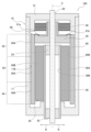
- the coreless motor 100 includes a rotating shaft 20, a coil 60, a commutator 50, a magnet 30, brushes 40, and a housing 10.
- the housing 10 is formed in a hollow cylindrical shape with both ends closed.
- the housing 10 houses a rotating shaft 20, a coil 60, a commutator 50, a magnet 30, and a brush 40 inside the hollow interior, and both ends of the rotating shaft 20 protrude outside the housing 10.
- the housing 10 includes a case 11 and a brush stand 12.
- the case 11 is formed in a cylindrical shape with one end closed.
- the case 11 is formed, for example, from a soft magnetic material.
- the brush base 12 is formed in a generally circular plate shape so as to close the open end of the case 11.
- the brush base 12 is formed, for example, from a resin.
- the brush base 12 is provided with a conductor connection member (not shown) that is connected to an external power source, and a brush 40 that is electrically connected to this connection member.
- a rotating shaft 20 is disposed at center C, which is the axis of the cylinder of the housing 10, penetrating the housing 10 and being rotatable around center C.
- a commutator 50 is fixed to the rotating shaft 20.
- a coil 60 is fixed to the commutator 50.
- the rotating shaft 20, coil 60, and commutator 50 form a rotor.
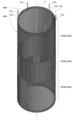
- the coil 60 is formed into a cylindrical shape by winding a conductor 61 (see FIGS. 3A and 3B).
- the coil 60 rotates integrally with the rotating shaft 20, with the center C of the rotating shaft 20 as its axis.
- the coil 60 is formed by assembling a plurality of coil elements each wound with a conductor 61 (e.g., copper wire).
- the coil 60 is formed so that the outer peripheral surface 60A of the cylinder does not come into contact with the inner peripheral surface 11B of the case 11. Details of the coil 60 will be described later.
- the commutator 50 is formed in a disk shape with a boss in the center through which the rotating shaft 20 passes.
- the outer periphery of the disk of the commutator 50 is bonded with an adhesive to the inner periphery of one end of the cylindrical coil 60 that is closer to the brush base 12, and is integrated with the coil 60.
- the commutator 50 is integrally connected to the rotating shaft 20 that passes through the boss, and as a result, the commutator 50 rotates around the center C together with the rotating shaft 20.
- the commutator 50 has a conductive member that is electrically connected to the terminals 61a, 61b (see Figures 2, 3A, and 3B) of each of the conductors 61 of the multiple coil elements that make up the coil 60, and this conductive member extends to the outer circumferential surface of the boss and contacts the brush 40 provided on the brush stand 12.
- the magnet 30 is arranged inside the cylinder of the coil 60 so as not to come into contact with the inner peripheral surface 60B of the coil 60.
- the magnet 30 is formed in a cylindrical shape with the center C as its axis.
- the magnet 30 is formed so that the outer peripheral surface 30A does not come into contact with the inner peripheral surface 60B of the coil 60.
- the inner peripheral surface 30B of the magnet 30 is fixed to the outer peripheral surface of a cylindrical support member 28 fixed to the case 11.
- the magnet 30 is indirectly fixed to the case 11 and does not displace relative to the case 11.
- Bearings 25 are arranged on both ends of the support member 28 in the longitudinal direction inside the support member 28, and the rotating shaft 20 is supported by these two bearings 25 so as to be freely rotatable.
- the coil 60 is basically made up of conductors 61 joined together with adhesive, and does not have a core such as an iron core. For this reason, the coil 60 is lighter than a coil with a core.
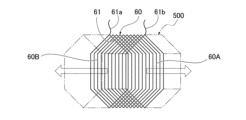
- the coil 60 is made by winding the conductor 61 around the outer periphery of a winding jig 500, for example, in the shape of a hexagonal prism, with the cross section being hexagonal.
- the position at which the conductor 61 is wound is shifted slightly in the axial direction of the hexagonal prism for each turn of the winding (one turn around the outer periphery of the hexagonal prism), so that each turn of the coil 60 has a hexagonal (tortoiseshell) shape and forms a helical coil.
- the coil 60 shown in FIG. 3B is used as one coil element, and multiple such coil elements are connected in the axial direction of the hexagonal prism described above, and the ends in the axial direction are connected around the center C shown in FIG. 3B so that one face 60A of the planar coil element faces outward (outer circumferential face) and the other face 60B faces inward (inner circumferential face), forming the cylindrical coil 60 shown in FIG. 2.
- the method of forming the coil 60 is not limited to the method described above.
- the coil 60 thus formed is a tortoiseshell-shaped (hexagonal) coil 60, and as shown in FIG. 2, on both the outer peripheral surface 60A and the inner peripheral surface 60B of this coil 60, the conductor 61 has a parallel portion 62 that extends parallel to the axial direction (center C) of the rotating shaft 20, and two oblique portions 63, 64 that connect to both ends of the parallel portion 62.
- the conductor 61 of the oblique portions 63, 64 extends in a direction inclined by a predetermined angle ⁇ with respect to a plane (shown by a dashed line in FIG. 3B) perpendicular to the center C direction.
- the inclination angle ⁇ of the oblique portion 63 and the inclination angle ⁇ of the oblique portion 64 have different directions but the same absolute value.
- the parallel portion 62 on the outer peripheral surface 60A of the coil 60 is referred to as parallel portion 62a
- the parallel portion 62 on the inner peripheral surface 60B is referred to as parallel portion 62b.
- the oblique portions 63, 64 on the outer peripheral surface 60A of the coil 60 are referred to as oblique portions 63a, 64a
- the oblique portions 63, 64 on the inner peripheral surface 60B are referred to as oblique portions 63b, 64b.
- FIG. 4 is a diagram showing the positional relationship between the magnet 30 and the hexagonal shape of one turn of the coil 60.
- the magnet 30 in the coreless motor 100 of this embodiment is formed, for example, as shown in FIG. 4, with one N pole 30N and one S pole 30S formed on either side of the axis of the center C.
- the angular pitch ⁇ between the center of the N pole 30N and the center of the S pole 30S is referred to as the magnetic pole pitch ⁇ .
- the coil 60 in the coreless motor 100 of this embodiment is formed such that the two parallel parts 62, 62 in one turn of the hexagon are arranged at an angular interval (angular pitch) ⁇ around the axis of the center C of the magnet 30.
- the two parallel parts 62, 62 are the parts in one turn of the coil 60 where the angular interval around the axis of the center C is maximum.
- the angular pitch ⁇ is referred to as the coil pitch ⁇ .
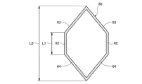
- Fig. 5 is a schematic diagram showing the overall length L0 of the coil 60 along the axial direction of the center C and the length L1 of the parallel portion 62.
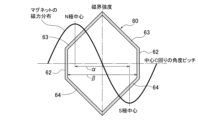
- Fig. 6 is a schematic diagram showing the relationship between the magnetic pole pitch ⁇ and the coil pitch ⁇ in the coreless motor 100, and also shows the magnetic force distribution represented by trigonometric functions, where the magnetic force of the magnet 30 is maximized at the center of the north pole 30N and the center of the south pole 30S.
- the coreless motor 100 has a coil 60 in which the ratio (length ratio) L1/L0 of the length L1 of the parallel portion 62 to the total length L0 along the axial direction of the center C is set to 0.25 (25% or more) or less and 0.45 (45% or less).
- the coreless motor 100 is formed with an over-pitch coil pitch ⁇ that is greater than the magnetic pole pitch ⁇ ( ⁇ ), for example.
- the coreless motor 100 is set so that the ratio ⁇ / ⁇ of the coil pitch ⁇ to the magnetic pole pitch ⁇ exceeds 1, and specifically, ⁇ / ⁇ is set to a range greater than 1.00 (100% ) and less than 1.25 (120% ) (1.00 ⁇ / ⁇ 1.25).
- the coreless motor 100 has, as an example, a magnetic pole pitch ⁇ of 180 degrees, and therefore the coil pitch ⁇ exceeds 180 degrees and is less than 225 degrees.
- B is the magnetic flux from the magnet 30
- I is the current flowing through the coil 60
- r is the radius of the coil 60 (the dimension along the radial direction R)
- L is the length of the coil 60 (the dimension along the center C).
- ⁇ is the inclination angle of the conductor 61 in the coil 60 with respect to a plane perpendicular to the center C direction (90 degrees at the parallel portion 62, ⁇ degrees at the upper oblique portion 63, 64), and ⁇ [degrees].
- the peak of the magnetic force of the magnet 30 acting on the parallel portion 62 decreases, but the magnetic flux acting on the oblique portions 63 and 64 at the angular position of the peak magnetic force increases, so that the magnetic flux acting on the coil 60 as a whole increases, and the maximum torque T of the coreless motor 100 increases.
- Figure 7 is a graph showing the maximum torque T output by one turn of wire 61 of coil 60 when the ratio L1/L0 of the length L1 of parallel portion 62 to the total length L0 of coil 60 is set to 0.25, 0.30, 0.35, 0.40, 0.45 (25, 30, 35, 40, 45 [%]) for each coil 60, and the ratio ⁇ / ⁇ of coil pitch ⁇ to magnetic pole pitch ⁇ is set to 0.95, 0.10, 1.05, 1.10, 1.25 (95, 100, 105, 110, 125 [%]).
- FIG. 7 shows the maximum torque T output by a tortoiseshell-shaped coil in which the hypotenuses 63, 64 of the coil 60 are formed in an arc shape. Note that in the case of a tortoiseshell-shaped coil in which the hypotenuses 63, 64 of the coil 60 are formed in a straight line, the maximum torque T output by the coil is slightly lower than the maximum torque T shown in FIG. 7, but the change in maximum torque T with respect to the change in the ratio ⁇ / ⁇ is the same as the graph shown in FIG. 7.
- the coreless motor 100 of this embodiment has a ratio L1/L0 of the length L1 of the parallel portion 62 to the total length L0 of the coil 60 set to 0.25, 0.30, 0.35, 0.40, 0.45 (25, 30, 35, 40, 45% [%]), and a ratio ⁇ / ⁇ of the coil pitch ⁇ to the magnetic pole pitch ⁇ set to a range exceeding 1.00 (100% [%]) and not exceeding 1.25 (125% [%]).
- the coreless motor 100 of this embodiment is formed with an over-pitch, in which the coil pitch ⁇ is greater than the magnetic pole pitch ⁇ .
- the ratio ⁇ / ⁇ of the coil pitch ⁇ to the magnetic pole pitch ⁇ is 1.05 (105[%]) or more and 1.10 (110[%]) or less, the maximum torque T can be maximized. Therefore, in the coreless motor 100, it is preferable that the ratio ⁇ / ⁇ of the coil pitch ⁇ to the magnetic pole pitch ⁇ is in the above-mentioned range.
- the upper limit of the ratio ⁇ / ⁇ of the coil pitch ⁇ to the magnetic pole pitch ⁇ is set to 1.25 (125%]) because if the ratio ⁇ / ⁇ is greater than this, it becomes difficult for the coreless motor 100 to output a sufficient maximum torque T.
- the coreless motor 100 of this embodiment can change the maximum torque T of the coreless motor 100 simply by setting the ratio ⁇ / ⁇ of the coil pitch ⁇ to the magnetic pole pitch ⁇ to greater than 100% without changing the size or strength of the coreless motor, such as by lengthening the dimension of the parallel portion 62 of the coil 60 in the coreless motor or increasing the number of turns of the conductor wire of the coil 60.
- the maximum torque T of the coreless motor 100 can be changed, as well as other characteristics of the coreless motor 100.
- the coreless motor 100 can, for example, reduce its rotation speed.
- the magnet 30 is formed with one north pole 30N and one south pole 30S, but the magnet 30 in the coreless motor 100 of this embodiment may be formed with two north poles 30N and two south poles 30S.
- the magnetic pole pitch ⁇ is 90 degrees, and based on the conditional equation 1.00 ⁇ / ⁇ 1.25 for the ratio ⁇ of the coil pitch ⁇ to the magnetic pole pitch ⁇ , the coil pitch ⁇ may be set to be greater than 90 degrees and less than or equal to 112.5 degrees.
- the coil pitch ⁇ in order to increase the maximum torque T, should be set to more than 90 degrees and less than or equal to 103.5 degrees, based on the conditional expression 1.00 ⁇ / ⁇ 1.15 for the ratio ⁇ / ⁇ of the coil pitch ⁇ to the magnetic pole pitch ⁇ .
- the coil pitch ⁇ in order to maximize the maximum torque T, should be set to more than 94.5 degrees and less than or equal to 99 degrees, based on the conditional expression 1.05 ⁇ / ⁇ 1.10 for the ratio ⁇ / ⁇ of the coil pitch ⁇ to the magnetic pole pitch ⁇ .
- the magnet 30 in the coreless motor 100 of this embodiment may be formed with n (3 ⁇ n) north poles 30N and south poles 30S.
- the magnetic pole pitch ⁇ is 180/n [degrees]
- the coil pitch ⁇ may be set to be greater than 180/n [degrees] and less than or equal to 225/n [degrees].
- the coil pitch ⁇ in order to increase the maximum torque T, should be set to more than 180/n [degrees] and less than or equal to 207/n [degrees] based on the conditional expression 1.00 ⁇ / ⁇ 1.15 for the ratio ⁇ / ⁇ of the coil pitch ⁇ to the magnetic pole pitch ⁇ .
- the coil pitch ⁇ in order to maximize the maximum torque T, should be set to more than 189/n [degrees] and less than or equal to 198/n [degrees] based on the conditional expression 1.05 ⁇ / ⁇ 1.10 for the ratio ⁇ / ⁇ of the coil pitch ⁇ to the magnetic pole pitch ⁇ .
- the coreless motor 100 of this embodiment can increase the maximum torque T that can be output as the length ratio L1/L0 increases, but as the length ratio L1/L0 increases, the cross-sectional area of the conductor 61 in the direction perpendicular to the center C at the oblique sides 63 and 64 increases, and as a result, the space factor of the conductor 61 at the parallel portion 62 decreases.
- the space factor of the conductor 61 in the parallel portion 62 becomes smaller than a predetermined value, the strength of the parallel portion 62 decreases, and the coil 60 may be deformed by the centrifugal force acting when rotating around the center C, and may come into contact with the housing 10. For this reason, the coil 60 needs to have a strength sufficient to prevent it from deforming at the rated rotation of the coreless motor 100.
- the upper limit of the length ratio L1/L0 is set to 0.75 (75%), taking into account the required strength of the coil 60.
- the lower limit of the length ratio L1/L0 of the coil 60 is set to 0.25 (25%), because this makes it easier for the coreless motor 100 to output the normally required minimum maximum torque T. If the length ratio L1/L0 is smaller than 0.25 (25%), it becomes difficult for the coreless motor 100 to output sufficient maximum torque T.
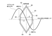
- Fig. 8 is a schematic diagram equivalent to Fig. 6, showing a modified example in which the coil pitch ⁇ is formed at a short pitch smaller than the magnetic pole pitch ⁇ ( ⁇ ).
- the coreless motor 100 of the embodiment described above is formed at an over-pitch in which the coil pitch ⁇ is larger than the magnetic pole pitch ⁇ , but the coreless motor according to the present invention is not limited to one having an over-pitch coil.
- the coreless motor according to the modified example which is another embodiment of the present invention, may be formed at a short pitch in which the coil pitch ⁇ is smaller than the magnetic pole pitch ⁇ ( ⁇ ), as shown in Fig. 8, for example.
- the ratio ⁇ / ⁇ of the coil pitch ⁇ to the magnetic pole pitch ⁇ can be set to a range less than 1.00 (100%; ⁇ / ⁇ 1.00), for example, in the range of 0.90 (90%; 90%; 90%; 0.90 ⁇ / ⁇ 1.00).
- the coreless motor of this modified example configured in this way has a short pitch ratio ⁇ / ⁇ of the coil pitch ⁇ to the magnetic pole pitch ⁇ , which is less than 1.00 (100%]), and the ratio ⁇ / ⁇ can be set to a range of, for example, 0.90 (90%] or more and less than 1.00 (100%]), thereby changing the characteristics of the coreless motor.
- the ratio ⁇ / ⁇ of the coil pitch ⁇ to the magnetic pole pitch ⁇ is set to a short pitch of less than 1.00 (100[%]), and the ratio ⁇ / ⁇ is set to a range of, for example, 0.90 (90[%]) or more and less than 1.00 (100[%]), thereby specifically, for example, increasing the rotation speed of the coreless motor.
- the present invention when it is desired to increase the rotation speed by increasing the number of rotations, the number of turns of the conductor 61 in the coil 60 is reduced in order to increase the rotation speed.
- reducing the number of turns of the conductor 61 in the coil 60 can result in a decrease in the rigidity of the coil 60.
- the coreless motor of the modified example does not reduce the number of turns of the conductor 61 in the coil 60, so there is no possibility of the stiffness of the coil 60 being reduced.
- the coreless motor 100 in the above-described embodiment and modified example is an outer rotor type coreless motor in which the coil 60 is arranged outside the magnet 30, but the coreless motor according to the present invention is not limited to an outer rotor type coreless motor, and may be an inner rotor type coreless motor in which the coil 60 is arranged inside the magnet 30.
- the outer peripheral surface of the magnet 30 is fixed to, for example, the inner peripheral surface of the case 11.
- the coreless motor according to the present invention is not limited to a coreless motor having a tortoise-shell shaped coil in which the hypotenuses 63, 64 of the coil 60 are formed in a straight line, but may be a coreless motor having a tortoise-shell shaped coil in which the hypotenuses 63, 64 of the coil 60 are formed in a curved line (e.g., a circular arc, an elliptical arc, a parabola).
- a curved line e.g., a circular arc, an elliptical arc, a parabola
- the coreless motor according to the present invention is not limited to a coreless motor with a tortoiseshell-shaped (hexagonal) coil, but may be a coreless motor with a coil of other shapes (e.g., diamond, square, circle, ellipse).
- the portions corresponding to the two parallel portions 62, 62 of the coil 60 are, for example, two vertices that face each other in the direction around the axis of the center C when the coil is diamond-shaped.
Landscapes
- Engineering & Computer Science (AREA)
- Power Engineering (AREA)
- Dc Machiner (AREA)
Priority Applications (5)
| Application Number | Priority Date | Filing Date | Title |
|---|---|---|---|
| EP23930387.8A EP4693852A1 (en) | 2023-03-28 | 2023-03-28 | Coreless motor |
| KR1020257026809A KR20250135261A (ko) | 2023-03-28 | 2023-03-28 | 코어리스 모터 |
| CN202380092004.4A CN120569887A (zh) | 2023-03-28 | 2023-03-28 | 无芯电机 |
| JP2025509366A JPWO2024201747A1 (https=) | 2023-03-28 | 2023-03-28 | |
| PCT/JP2023/012645 WO2024201747A1 (ja) | 2023-03-28 | 2023-03-28 | コアレスモータ |
Applications Claiming Priority (1)
| Application Number | Priority Date | Filing Date | Title |
|---|---|---|---|
| PCT/JP2023/012645 WO2024201747A1 (ja) | 2023-03-28 | 2023-03-28 | コアレスモータ |
Publications (1)
| Publication Number | Publication Date |
|---|---|
| WO2024201747A1 true WO2024201747A1 (ja) | 2024-10-03 |
Family
ID=92903571
Family Applications (1)
| Application Number | Title | Priority Date | Filing Date |
|---|---|---|---|
| PCT/JP2023/012645 Ceased WO2024201747A1 (ja) | 2023-03-28 | 2023-03-28 | コアレスモータ |
Country Status (5)
| Country | Link |
|---|---|
| EP (1) | EP4693852A1 (https=) |
| JP (1) | JPWO2024201747A1 (https=) |
| KR (1) | KR20250135261A (https=) |
| CN (1) | CN120569887A (https=) |
| WO (1) | WO2024201747A1 (https=) |
Citations (4)
| Publication number | Priority date | Publication date | Assignee | Title |
|---|---|---|---|---|
| JPS5256305A (en) * | 1975-11-01 | 1977-05-09 | Sony Corp | Coreless motor |
| JPS58139891U (ja) * | 1982-03-16 | 1983-09-20 | 株式会社三ツ葉電機製作所 | 直流モ−タ |
| JPH01186143A (ja) | 1988-01-19 | 1989-07-25 | Olympus Optical Co Ltd | 無鉄心電機子とその製造方法及び無鉄心電機子成形用金型 |
| JP2014193069A (ja) * | 2013-03-28 | 2014-10-06 | Minebea Co Ltd | コアレスモータ |
-
2023
- 2023-03-28 CN CN202380092004.4A patent/CN120569887A/zh active Pending
- 2023-03-28 EP EP23930387.8A patent/EP4693852A1/en active Pending
- 2023-03-28 JP JP2025509366A patent/JPWO2024201747A1/ja active Pending
- 2023-03-28 WO PCT/JP2023/012645 patent/WO2024201747A1/ja not_active Ceased
- 2023-03-28 KR KR1020257026809A patent/KR20250135261A/ko active Pending
Patent Citations (4)
| Publication number | Priority date | Publication date | Assignee | Title |
|---|---|---|---|---|
| JPS5256305A (en) * | 1975-11-01 | 1977-05-09 | Sony Corp | Coreless motor |
| JPS58139891U (ja) * | 1982-03-16 | 1983-09-20 | 株式会社三ツ葉電機製作所 | 直流モ−タ |
| JPH01186143A (ja) | 1988-01-19 | 1989-07-25 | Olympus Optical Co Ltd | 無鉄心電機子とその製造方法及び無鉄心電機子成形用金型 |
| JP2014193069A (ja) * | 2013-03-28 | 2014-10-06 | Minebea Co Ltd | コアレスモータ |
Also Published As
| Publication number | Publication date |
|---|---|
| CN120569887A (zh) | 2025-08-29 |
| KR20250135261A (ko) | 2025-09-12 |
| EP4693852A1 (en) | 2026-02-11 |
| JPWO2024201747A1 (https=) | 2024-10-03 |
Similar Documents
| Publication | Publication Date | Title |
|---|---|---|
| US8890387B2 (en) | Stator and motor | |
| US9287744B2 (en) | Winding structure, rotating electric machine, and rotating electric machine manufacturing method | |
| US7269890B2 (en) | Slotless rotary electric machine and manufacturing method of coils for such a machine | |
| JP5248751B2 (ja) | スロットレス永久磁石型回転電機 | |
| JP6138360B2 (ja) | 回転電機およびその製造方法 | |
| JP2003164089A (ja) | 回転磁界型電動機の固定子及びその製造方法 | |
| JP2010130831A (ja) | アウターロータ型ブラシレスモータ | |
| JP7342654B2 (ja) | 回転電機 | |
| JP3322954B2 (ja) | 小型モータの組立式整流子 | |
| WO2024201747A1 (ja) | コアレスモータ | |
| JP7850344B2 (ja) | コアレスモータ | |
| GB2092833A (en) | Flat coil element for an electric motor and method of manufacturing the same | |
| JP2006271142A (ja) | 回転機 | |
| JP2015107029A (ja) | 電機子及び回転電機 | |
| JP7515028B1 (ja) | コアレスモータ | |
| JP7484303B2 (ja) | モータ | |
| JP5230303B2 (ja) | ステッピングモータ | |
| JP7195180B2 (ja) | 固定子、及び回転電機 | |
| KR102693855B1 (ko) | 축 방향 자속 영구자석 전동기 | |
| JP2004080950A (ja) | 回転電機の電機子 | |
| CN223928138U (zh) | 定子以及电机 | |
| US20250239898A1 (en) | Magnetic core, coil-equipped magnetic core, rotating electrical machine, and brushless motor | |
| JP2008283849A (ja) | 直流モータ | |
| JP2023179026A (ja) | 着磁ヨークおよび回転電機 | |
| JPH0956131A (ja) | コアレス型ブラシレスモータ |
Legal Events
| Date | Code | Title | Description |
|---|---|---|---|
| 121 | Ep: the epo has been informed by wipo that ep was designated in this application |
Ref document number: 23930387 Country of ref document: EP Kind code of ref document: A1 |
|
| WWE | Wipo information: entry into national phase |
Ref document number: 2025509366 Country of ref document: JP |
|
| WWE | Wipo information: entry into national phase |
Ref document number: 202380092004.4 Country of ref document: CN |
|
| WWE | Wipo information: entry into national phase |
Ref document number: 202517074938 Country of ref document: IN |
|
| ENP | Entry into the national phase |
Ref document number: 1020257026809 Country of ref document: KR Free format text: ST27 STATUS EVENT CODE: A-0-1-A10-A15-NAP-PA0105 (AS PROVIDED BY THE NATIONAL OFFICE) |
|
| WWE | Wipo information: entry into national phase |
Ref document number: 1020257026809 Country of ref document: KR |
|
| WWP | Wipo information: published in national office |
Ref document number: 202517074938 Country of ref document: IN Ref document number: 202380092004.4 Country of ref document: CN |
|
| WWE | Wipo information: entry into national phase |
Ref document number: 2023930387 Country of ref document: EP |
|
| NENP | Non-entry into the national phase |
Ref country code: DE |
|
| ENP | Entry into the national phase |
Ref document number: 2023930387 Country of ref document: EP Effective date: 20251028 |
|
| ENP | Entry into the national phase |
Ref document number: 2023930387 Country of ref document: EP Effective date: 20251028 |
|
| ENP | Entry into the national phase |
Ref document number: 2023930387 Country of ref document: EP Effective date: 20251028 |
|
| ENP | Entry into the national phase |
Ref document number: 2023930387 Country of ref document: EP Effective date: 20251028 |
|
| ENP | Entry into the national phase |
Ref document number: 2023930387 Country of ref document: EP Effective date: 20251028 |
|
| ENP | Entry into the national phase |
Ref document number: 2023930387 Country of ref document: EP Effective date: 20251028 |
|
| ENP | Entry into the national phase |
Ref document number: 2023930387 Country of ref document: EP Effective date: 20251028 |
|
| ENP | Entry into the national phase |
Ref document number: 2023930387 Country of ref document: EP Effective date: 20251028 |
|
| WWP | Wipo information: published in national office |
Ref document number: 2023930387 Country of ref document: EP |