WO2024201733A1 - 光波形制御装置、光伝送システム、および光波形制御方法 - Google Patents
光波形制御装置、光伝送システム、および光波形制御方法 Download PDFInfo
- Publication number
- WO2024201733A1 WO2024201733A1 PCT/JP2023/012601 JP2023012601W WO2024201733A1 WO 2024201733 A1 WO2024201733 A1 WO 2024201733A1 JP 2023012601 W JP2023012601 W JP 2023012601W WO 2024201733 A1 WO2024201733 A1 WO 2024201733A1
- Authority
- WO
- WIPO (PCT)
- Prior art keywords
- optical
- noise ratio
- optical signal
- devices
- signal
- Prior art date
- Legal status (The legal status is an assumption and is not a legal conclusion. Google has not performed a legal analysis and makes no representation as to the accuracy of the status listed.)
- Pending
Links
Images


Classifications
-
- H—ELECTRICITY
- H04—ELECTRIC COMMUNICATION TECHNIQUE
- H04B—TRANSMISSION
- H04B10/00—Transmission systems employing electromagnetic waves other than radio-waves, e.g. infrared, visible or ultraviolet light, or employing corpuscular radiation, e.g. quantum communication
- H04B10/27—Arrangements for networking
-
- H—ELECTRICITY
- H04—ELECTRIC COMMUNICATION TECHNIQUE
- H04B—TRANSMISSION
- H04B10/00—Transmission systems employing electromagnetic waves other than radio-waves, e.g. infrared, visible or ultraviolet light, or employing corpuscular radiation, e.g. quantum communication
- H04B10/29—Repeaters
- H04B10/291—Repeaters in which processing or amplification is carried out without conversion of the main signal from optical form
- H04B10/293—Signal power control
- H04B10/294—Signal power control in a multiwavelength system, e.g. gain equalisation
-
- H—ELECTRICITY
- H04—ELECTRIC COMMUNICATION TECHNIQUE
- H04J—MULTIPLEX COMMUNICATION
- H04J14/00—Optical multiplex systems
- H04J14/02—Wavelength-division multiplex systems
Definitions
- the present invention relates to an optical waveform control device, an optical transmission system, and an optical waveform control method, and in particular to an optical waveform control device, an optical transmission system, and an optical waveform control method used together with an optical submarine cable system.
- Optical undersea cable systems that connect continents with optical fibers play an important role as infrastructure supporting international communication networks.
- Optical undersea cable systems are composed of submarine cables that accommodate optical fibers, submarine repeaters equipped with optical amplifiers, submarine branching devices that branch optical signals, and terminal equipment installed at landing stations.
- An example of such an optical undersea cable system is described in Patent Document 1.
- the distance from the landing station (CLS) to the data center or POP can be several hundred kilometers, so long-distance terrestrial optical transmission with an in-line amplifier (ILA) is required.
- ILA in-line amplifier
- wavelength-multiplexed optical signals propagating through optical undersea cables are required to have a constant optical signal-to-noise ratio (OSNR) for each wavelength channel.
- OSNR optical signal-to-noise ratio
- the object of the present invention is to provide an optical waveform control device, an optical transmission system, and an optical waveform control method that solve the above-mentioned problem of the complexity of control when the termination point of an optical signal propagating through an optical submarine cable is extended in an optical transmission system.
- the optical waveform control device of the present invention has a communication means for communicating with each of a plurality of optical devices including at least a first optical device and a second optical device located after the first optical device, an optical signal-to-noise ratio acquisition means for receiving, via the communication means, an individual optical signal-to-noise ratio, which is the optical signal-to-noise ratio for each wavelength channel of a wavelength-multiplexed optical signal propagating through the plurality of optical devices, and an average optical signal-to-noise ratio, which is the average of the individual optical signal-to-noise ratios, a first control means for controlling the optical output power of the first optical device via the communication means so that the optical input power of the optical amplifier provided in the second optical device becomes a predetermined value, and a second control means for controlling at least one of the plurality of optical devices via the communication means so that the individual optical signal-to-noise ratio becomes equal to the average optical signal-to-noise ratio.
- the optical transmission system of the present invention comprises a plurality of optical devices including at least a first optical device and a second optical device located behind the first optical device, and an optical waveform control device, the second optical device having an optical amplifier, and the optical waveform control device comprises communication means for communicating with each of the plurality of optical devices, optical signal-to-noise ratio acquisition means for receiving, via the communication means, an individual optical signal-to-noise ratio, which is the optical signal-to-noise ratio for each wavelength channel of a wavelength-multiplexed optical signal propagating through the plurality of optical devices, and an average optical signal-to-noise ratio, which is the average of the individual optical signal-to-noise ratios, a first control means for controlling the optical output power of the first optical device via the communication means so that the optical input power of the optical amplifier becomes a predetermined value, and a second control means for controlling at least one of the plurality of optical devices via the communication means so that the individual optical signal-to-noise ratio becomes equal to the average optical signal
- the optical waveform control method of the present invention receives an individual optical signal-to-noise ratio, which is the optical signal-to-noise ratio for each wavelength channel, and an average optical signal-to-noise ratio, which is the average of the individual optical signal-to-noise ratios, of a wavelength-multiplexed optical signal propagating through a plurality of optical devices including at least a first optical device and a second optical device located downstream of the first optical device, controls the optical output power of the first optical device so that the optical input power of the optical amplifier included in the second optical device becomes a predetermined value, and controls at least one of the plurality of optical devices so that the individual optical signal-to-noise ratio becomes equal to the average optical signal-to-noise ratio.
- an individual optical signal-to-noise ratio which is the optical signal-to-noise ratio for each wavelength channel
- an average optical signal-to-noise ratio which is the average of the individual optical signal-to-noise ratios
- the optical waveform control device, optical transmission system, and optical waveform control method of the present invention can simplify control in an optical transmission system even when the termination point of an optical signal propagating through an optical submarine cable is extended.
- FIG. 11 is a block diagram showing a configuration of an optical transmission system including an optical waveform controller according to a second embodiment of the present invention. 11 is a diagram showing an optical spectrum of a wavelength-multiplexed optical signal transmitted by a first optical device constituting an optical transmission system according to a second embodiment of the present invention; FIG.
- FIG. 11 is a diagram showing an optical spectrum of a wavelength-multiplexed optical signal in a third optical device constituting an optical transmission system according to a second embodiment of the present invention.
- FIG. 10 is a flowchart illustrating an optical waveform control method according to a second embodiment of the present invention.
- FIG. 11 is a block diagram showing a configuration of an optical transmission system including an optical waveform controller according to a third embodiment of the present invention.
- FIG. 11 is a diagram showing an optical spectrum of a wavelength-multiplexed optical signal transmitted by a first optical device constituting an optical transmission system according to a third embodiment of the present invention.
- FIG. 11 is a diagram illustrating an optical spectrum of a wavelength-multiplexed optical signal in a third optical device constituting an optical transmission system according to a third embodiment of the present invention.
- FIG. 11 is a block diagram showing another configuration of an optical transmission system including an optical waveform controller according to the third embodiment of the present invention.
- 10 is a flowchart illustrating an optical waveform control method according to a third embodiment of the present invention.
- 10 is a flowchart illustrating an optical waveform control method according to a third embodiment of the present invention.
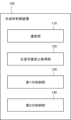
- First Embodiment 1 is a block diagram showing the configuration of an optical waveform controller 100 according to a first embodiment of the present invention.
- the optical waveform controller 100 has a communication unit (communication means) 110, an optical signal to noise ratio acquisition unit (optical signal to noise ratio acquisition means) 120, a first control unit (first control means) 130, and a second control unit (second control means) 140.
- the optical waveform controller 100 is preferably used together with an optical submarine cable system.
- the communication unit 110 communicates with each of a plurality of optical devices including at least a first optical device and a second optical device located behind the first optical device.
- the optical signal to noise ratio acquisition unit 120 receives the individual optical signal to noise ratio and the average optical signal to noise ratio via the communication unit 110.
- the individual optical signal to noise ratio is the optical signal to noise ratio (Optical Signal to Noise Ratio: OSNR) for each wavelength channel of the wavelength multiplexed optical signal propagating through the plurality of optical devices.
- the average optical signal to noise ratio is the average of the individual optical signal to noise ratios.
- the first control unit 130 controls the optical output power of the first optical device via the communication unit 110 so that the optical input power of the optical amplifier included in the second optical device becomes a predetermined value.
- the second control unit 140 then controls at least one of the multiple optical devices via the communication unit 110 so that the individual optical signal to noise ratio becomes equal to the average optical signal to noise ratio. This makes it possible to make the optical signal to noise ratio (OSNR) of each wavelength channel in the wavelength multiplexed optical signal optimal and constant.
- OSNR optical signal to noise ratio
- the optical waveform control device 100 of this embodiment is configured such that the optical signal-to-noise ratio acquisition unit 120 receives the individual optical signal-to-noise ratio and the average optical signal-to-noise ratio, and the first control unit 130 and the second control unit 140 control multiple optical devices. Therefore, it is not necessary to individually adjust the equipment of multiple optical devices such as a landing station (CLS), an in-line amplifier (ILA), and a POP device. As a result, control can be simplified in the optical transmission system.
- CLS landing station
- IVA in-line amplifier
- POP device POP device
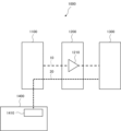
- FIG. 2 shows the configuration of an optical transmission system 1000 equipped with an optical waveform control device according to this embodiment.
- the optical transmission system 1000 has a plurality of optical devices including at least a first optical device 1100 and a second optical device 1200 located after the first optical device 1100, and an optical waveform control device 1400.
- the configuration of the optical waveform control device 1400 is similar to the configuration of the optical waveform control device 100 described above.
- FIG. 2 also shows a third optical device 1300 located at the last stage of the plurality of optical devices.
- multiple optical devices including a first optical device 1100, a second optical device 1200, and a third optical device 1300 are connected to each other via optical fibers installed on land.
- the first optical device 1100 is typically installed at a connection point (Point of Presence: POP) with a data center or a backbone network.
- the second optical device 1200 can be configured to include an optical amplifier 1210 such as an in-line amplifier (ILA).
- the third optical device 1300 can typically be installed at a cable landing station (CLS) of an optical submarine cable system and can be configured to be connected to an optical submarine cable installed on the seabed. With this configuration, the termination point of the optical signal propagating through the optical submarine cable can be extended to a data center or POP.
- the communication unit 1410 (110 in FIG. 1) included in the optical waveform control device 1400 communicates with multiple optical devices by in-band communication signals 20 of an in-band method via an optical transmission path through which the wavelength multiplexed optical signal 10 propagates.
- WSS wavelength selective switches
- a configuration can be made in which optical transceivers are attached to ports of switching hubs (layer 2 switches) connected to each of the first optical device 1100, the second optical device 1200, and the third optical device 1300. Using these optical transceivers, optical signal information can be obtained via the optical transmission path by in-band communication signals 20, and the devices can be configured.
- the third optical device 1300 can be configured to include an optical channel monitor (OCM) or an optical spectrum analyzer (OSA).
- OCM optical channel monitor
- OSA optical spectrum analyzer
- the first control unit 130 included in the optical waveform control device 1400 controls the optical output power of the first optical device 1100 via the communication unit 1410 so that the optical input power of the optical amplifier 1210 included in the second optical device 1200 becomes a predetermined value.
- the optical amplifier 1210 is typically an amplifier using erbium-doped fiber (Erbium Doped Fiber Amplifier: EDFA).
- the predetermined value of the optical input power of the optical amplifier 1210 can be an optical input power value optimized to maximize the average optical signal to noise ratio.
- the average optical signal to noise ratio is the average of the individual optical signal to noise ratios in the wavelength band of the wavelength multiplexed optical signal 10, as described above.
- the optical input power of the optical amplifier 1210 changes, the wavelength dependency of the gain profile of the optical amplifier 1210 also changes. Therefore, there is an optical input power value optimized to maximize the average optical signal to noise ratio according to the gain characteristics of the optical amplifier 1210.
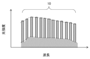
- the second control unit 140 included in the optical waveform control device 1400 controls at least one of the multiple optical devices via the communication unit 110 so that the individual optical signal to noise ratio is equal to the average optical signal to noise ratio.
- OSNR optical signal to noise ratio
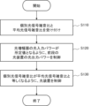
- an individual optical signal to noise ratio and an average optical signal to noise ratio of a wavelength-multiplexed optical signal propagating through a plurality of optical devices are received (step S110).
- the plurality of optical devices includes at least a first optical device and a second optical device located after the first optical device.
- the individual optical signal to noise ratio is the optical signal to noise ratio for each wavelength channel of the wavelength-multiplexed optical signal.
- the average optical signal to noise ratio is the average of the individual optical signal to noise ratios.
- the optical output power of the first optical device is controlled so that the optical input power of the optical amplifier included in the second optical device becomes a predetermined value (step S120). Then, at least one of the multiple optical devices is controlled so that the individual optical signal to noise ratio becomes equal to the average optical signal to noise ratio (step S130).
- the optical signal noise ratio acquisition means performs the operation in step S110.
- the first control means performs the operation in step S120.
- the second control means performs the operation in step S130.
- the optical waveform control method of this embodiment is configured to accept individual optical signal-to-noise ratios and average optical signal-to-noise ratios and control multiple optical devices. Therefore, there is no need to individually adjust the equipment of multiple optical devices, such as landing stations (CLS), in-line amplifiers (ILA), and POP devices. As a result, control can be simplified in optical transmission systems.
- the predetermined value of the optical input power of the optical amplifier described above is an optical input power value optimized to maximize the average optical signal-to-noise ratio.
- the configuration may further include communication with multiple optical devices using an in-band method via an optical transmission path along which wavelength-multiplexed optical signals propagate.
- the optical waveform control device 100, optical transmission system 1000, and optical waveform control method of this embodiment can simplify control in an optical transmission system even when the termination point of an optical signal propagating through an optical submarine cable is extended.
- the configuration of the optical waveform controller according to this embodiment is similar to the configuration of the optical waveform controller 100 according to the first embodiment shown in Fig. 1. That is, the optical waveform controller 100 has a communication section (communication means) 110, an optical signal to noise ratio acquisition section (optical signal to noise ratio acquisition means) 120, a first control section (first control means) 130, and a second control section (second control means) 140.
- the optical waveform controller 100 is preferably used together with an optical submarine cable system.
- the communication unit 110 communicates with each of a plurality of optical devices including at least a first optical device and a second optical device located behind the first optical device.
- the optical signal to noise ratio acquisition unit 120 receives the individual optical signal to noise ratio and the average optical signal to noise ratio via the communication unit 110.
- the individual optical signal to noise ratio is the optical signal to noise ratio (Optical Signal to Noise Ratio: OSNR) for each wavelength channel of the wavelength multiplexed optical signal propagating through the plurality of optical devices.
- the average optical signal to noise ratio is the average of the individual optical signal to noise ratios.
- the first control unit 130 controls the optical output power of the first optical device via the communication unit 110 so that the optical input power of the optical amplifier included in the second optical device becomes a predetermined value.
- the second control unit 140 controls at least one of the multiple optical devices via the communication unit 110 so that the individual optical signal to noise ratio becomes equal to the average optical signal to noise ratio.
- the first control unit (first control means) 130 is configured to control the optical output power of the first optical device by controlling the optical attenuator provided in the first optical device.
- FIG. 4 shows the configuration of an optical transmission system 2000 equipped with an optical waveform control device according to this embodiment.
- the optical transmission system 2000 has a plurality of optical devices including at least a first optical device 1100 and a second optical device 1200 located after the first optical device 1100, and an optical waveform control device 1400.
- the configuration of the optical waveform control device 1400 is similar to the configuration of the optical waveform control device 100 described above.
- FIG. 4 also shows a second optical device 2200 included in the plurality of optical devices and a third optical device 1300 located at the last stage of the plurality of optical devices. Since the second optical device 2200 is located after the second optical device 1200, the second optical device 1200 functions as a first optical device 2100 in relation to the second optical device 2200.
- the first optical device 1100 is typically installed at a data center or a connection point (POP) with a backbone network.
- the third optical device 1300 is typically installed at a landing station (CLS) of an optical submarine cable system, and can be configured to be connected to an optical submarine cable installed on the seabed. With this configuration, the termination point of the optical signal propagating through the optical submarine cable can be extended to the data center or POP.
- the first optical devices 1100 and 2100 are equipped with optical attenuators 1110 and 2110, and the second optical devices 1200 and 2200 are equipped with optical amplifiers 1210 and 2210.
- the second optical device 2200 is located before the third optical device 1300, which is the last stage. Therefore, the second optical device 2200 functions as the first optical device with respect to the third optical device 1300, so a configuration equipped with an optical attenuator 2111 is shown.
- the optical attenuators 1110, 2110, and 2111 are typically variable optical attenuators (VOA). Wavelength Selective Switches (WSS) may also be used as the optical attenuators 1110, 2110, and 2111.
- VOA variable optical attenuators
- WSS Wavelength Selective Switches
- the first control unit 130 (see FIG. 1) provided in the optical waveform control device 1400 controls the optical output power of the first optical devices 1100, 2100 so that the optical input power of the optical amplifiers 1210, 2210 provided in the second optical devices 1200, 2200 becomes a predetermined value.
- the first control unit 130 controls the optical output power of the first optical devices 1100, 2100 by controlling the optical attenuators 1110, 2110 provided in the first optical devices 1100, 2100.
- the predetermined value of the optical input power of the optical amplifiers 1210, 2210 is an optical input power value optimized to maximize the average optical signal-to-noise ratio.
- the optical input power of the optical amplifiers 1210 and 2210 is adjusted by the first control unit 130, starting with the optical device that transmits the wavelength-multiplexed optical signal 10, and then sequentially controlling the optical devices in the subsequent stages. This makes it possible to optimize all the optical amplifiers 1210 and 2210 and maximize the average optical signal-to-noise ratio.
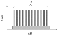
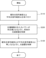
- Figure 5A shows an example of the optical spectrum of the wavelength-multiplexed optical signal 10 sent by the first optical device 1100 located at the first stage among the multiple optical devices.
- the wavelength-multiplexed optical signal 10 dummy light shaped into a comb-shaped waveform by controlling the band of amplified spontaneous emission (ASE) to either odd or even channels, as shown in Figure 5A, can be used.
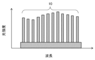
- Figure 5B shows an example of the optical spectrum of the wavelength-multiplexed optical signal 10 in the third optical device 1300 at the last stage.
- the wavelength-multiplexed optical signal 10 has the maximum average optical signal-to-noise ratio.
- the second control unit 140 included in the optical waveform control device 1400 controls at least one of the multiple optical devices via the communication unit 110 so that the individual optical signal to noise ratio is equal to the average optical signal to noise ratio.
- OSNR optical signal to noise ratio
- an individual optical signal to noise ratio and an average optical signal to noise ratio of a wavelength-multiplexed optical signal propagating through a plurality of optical devices are received (step S110).
- the plurality of optical devices includes at least a first optical device and a second optical device located after the first optical device.
- the individual optical signal to noise ratio is the optical signal to noise ratio for each wavelength channel of the wavelength-multiplexed optical signal.
- the average optical signal to noise ratio is the average of the individual optical signal to noise ratios.
- the optical output power of the first optical device is controlled so that the optical input power of the optical amplifier included in the second optical device is a predetermined value.
- the optical attenuator included in the first optical device is controlled (step S220).
- At least one of the optical devices is controlled so that the individual optical signal to noise ratio is equal to the average optical signal to noise ratio (step S130).
- the optical signal-to-noise ratio acquisition means performs the operation in step S110.
- the first control means performs the operation in step S220.
- the second control means performs the operation in step S130.
- the optical waveform control method of this embodiment is configured to accept individual optical signal-to-noise ratios and average optical signal-to-noise ratios and control multiple optical devices. Therefore, there is no need to individually adjust the equipment of multiple optical devices, such as landing stations (CLS), in-line amplifiers (ILA), and POP devices. As a result, control can be simplified in optical transmission systems.
- the optical waveform control device, optical transmission system 2000, and optical waveform control method of this embodiment can simplify control in an optical transmission system even when the termination point of an optical signal propagating through an optical submarine cable is extended.
- the configuration of the optical waveform controller according to this embodiment is similar to the configuration of the optical waveform controller 100 according to the first embodiment shown in Fig. 1. That is, the optical waveform controller 100 has a communication section (communication means) 110, an optical signal-to-noise ratio acquisition section (optical signal-to-noise ratio acquisition means) 120, a first control section (first control means) 130, and a second control section (second control means) 140.
- the optical waveform controller 100 is preferably used together with an optical submarine cable system.
- the communication unit 110 communicates with each of a plurality of optical devices including at least a first optical device and a second optical device located after the first optical device.
- the optical signal to noise ratio acquisition unit 120 receives the individual optical signal to noise ratio and the average optical signal to noise ratio via the communication unit 110.
- the individual optical signal to noise ratio is the optical signal to noise ratio (OSNR) for each wavelength channel of the wavelength multiplexed optical signal propagating through the plurality of optical devices.
- the average optical signal to noise ratio is the average of the individual optical signal to noise ratios.
- the first control unit 130 controls the optical output power of the first optical device via the communication unit 110 so that the optical input power of the optical amplifier included in the second optical device becomes a predetermined value.
- the second control unit 140 controls at least one of the multiple optical devices via the communication unit 110 so that the individual optical signal to noise ratio becomes equal to the average optical signal to noise ratio.
- the second control unit (second control means) 140 controls a dummy light generator provided in at least one of the multiple optical devices, and adjusts the light intensity of the dummy light emitted by this dummy light generator.
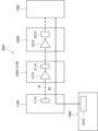
- FIG. 7 shows the configuration of an optical transmission system 3000 equipped with an optical waveform control device according to this embodiment.
- the optical transmission system 3000 has a plurality of optical devices including at least a first optical device 1100 and a second optical device 1200 located after the first optical device 1100, and an optical waveform control device 1400. At least one of the plurality of optical devices is configured to include a dummy light generator.
- FIG. 7 shows a configuration in which the first optical device 1100 located at the first stage among the plurality of optical devices includes a dummy light generator 3110. The rest of the configuration is the same as the configuration of the optical transmission system 2000 according to the second embodiment.
- the first optical device 1100 is typically installed at a data center or a connection point (POP) with a backbone network.
- the third optical device 1300 is typically installed at a landing station (CLS) of an optical submarine cable system, and can be configured to be connected to an optical submarine cable installed on the seabed. With this configuration, the termination point of the optical signal propagating through the optical submarine cable can be extended to the data center or POP.
- the dummy light generator 3110 generates dummy light.
- an ASE (Amplified Spontaneous Emission) light source in which an amplifier using erbium-doped fiber (Erbium Doped Fiber Amplifier: EDFA) is in a state of no input signal can be used.
- EDFA Erbium Doped Fiber Amplifier
- the second control unit 140 (see FIG. 1) included in the optical waveform control device 1400 controls at least one of the multiple optical devices via the communication unit 1410 so that the individual optical signal-to-noise ratio is equal to the average optical signal-to-noise ratio.
- the second control unit 140 controls the dummy light generator 3110 and adjusts the optical intensity of the dummy light that the dummy light generator 3110 transmits.
- the second control unit 140 controls the dummy light generator 3110 to adjust each peak level of the wavelength multiplexed optical signal 10 so that the value of the individual optical signal to noise ratio is equal across the wavelength band of the wavelength multiplexed optical signal 10.
- the optical signal to noise ratio acquisition unit 120 provided in the optical waveform control device 1400 receives the individual optical signal to noise ratio and the average optical signal to noise ratio via the communication unit 110.
- the second control unit 140 adjusts each peak level of the wavelength multiplexed optical signal 10, for example, as follows. That is, if the individual optical signal to noise ratio of the target optical signal peak is higher than the average optical signal to noise ratio, the dummy light generator 3110 is controlled to reduce the peak level by the difference amount. On the other hand, if the individual optical signal to noise ratio of the target optical signal peak is lower than the average optical signal to noise ratio, the dummy light generator 3110 is controlled to increase the peak level by the difference amount.
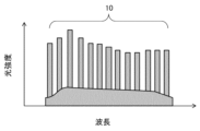
- FIG. 8A shows an example of the optical spectrum of the wavelength-multiplexed optical signal 10 sent by the dummy light generator 3110 after the second control unit 140 adjusts each peak level.
- FIG. 8B shows an example of the optical spectrum of the wavelength-multiplexed optical signal 10 at the last stage, the third optical device 1300, after propagating through an optical fiber connecting multiple optical devices.
- the optical waveform control device and optical transmission system 3000 of this embodiment can maintain a constant optical signal-to-noise ratio (OSNR) for each wavelength channel of the wavelength-multiplexed optical signal 10.
- OSNR optical signal-to-noise ratio
- the optical waveform control device 1400 is configured such that the second control unit 140 controls a dummy light generator provided in at least one of the multiple optical devices, and adjusts the optical intensity of the dummy light output by the dummy light generator.
- the configuration is not limited to this, and the second control unit 140 may be configured to control a wavelength selective switch (WSS) provided in at least one of the multiple optical devices, and adjust the optical intensity of the wavelength multiplexed optical signal 10 output by the wavelength selective switch.
- WSS wavelength selective switch
- FIG. 9 shows the configuration of an optical transmission system 3001 equipped with an optical waveform control device configured as described above.
- the optical transmission system 3001 at least one of the multiple optical devices is equipped with a wavelength selective switch (WSS).
- WSS wavelength selective switch
- FIG. 9 shows a configuration in which the second optical device 3200 is equipped with a wavelength selective switch 3210. Even in a configuration using the wavelength selective switch 3210, the optical signal to noise ratio (OSNR) of each wavelength channel of the wavelength multiplexed optical signal 10 can be made constant.
- OSNR optical signal to noise ratio
- an individual optical signal to noise ratio and an average optical signal to noise ratio of a wavelength-multiplexed optical signal propagating through a plurality of optical devices are received (step S110).
- the plurality of optical devices includes at least a first optical device and a second optical device located after the first optical device.
- the individual optical signal to noise ratio is the optical signal to noise ratio for each wavelength channel of the wavelength-multiplexed optical signal.
- the average optical signal to noise ratio is the average of the individual optical signal to noise ratios.
- the optical output power of the first optical device is controlled so that the optical input power of the optical amplifier included in the second optical device becomes a predetermined value (step S120).
- the optical intensity of the dummy light output by the dummy light generator included in at least one of the plurality of optical devices is adjusted (step S331).
- the optical intensity of the wavelength-multiplexed optical signal output by the wavelength selective switch included in at least one of the plurality of optical devices may be adjusted (step S332).
- the optical signal noise ratio acquisition means performs the operation in step S110.
- the first control means performs the operation in step S120.
- the second control means performs the operation in steps S331 and S332.
- the optical waveform control method of this embodiment is configured to accept individual optical signal-to-noise ratios and average optical signal-to-noise ratios and control multiple optical devices. Therefore, there is no need to individually adjust the equipment of multiple optical devices, such as landing stations (CLS), in-line amplifiers (ILA), and POP devices. As a result, control can be simplified in optical transmission systems.
- controlling the optical output power can include controlling the optical output power before and after the step of controlling at least one of the multiple optical devices.
- FIG. 11 shows a flowchart of the optical waveform control method in such a configuration.
- the step of controlling the optical output power (S120) can also be configured to control the optical output power before and after the step of controlling an optical device such as a dummy light generator or a wavelength selection switch (S330).
- the predetermined condition can be, for example, that the difference between the individual optical signal to noise ratio and the average optical signal to noise ratio is equal to or less than a predetermined amount over the entire wavelength band of the wavelength multiplexed optical signal.
- the predetermined condition can be that the number of times steps S120 and S330 have been performed reaches a predetermined number. If the predetermined condition is satisfied (step S340/YES), the process ends. If the predetermined condition is not satisfied (step S340/NO), the process returns to the step (S120) of controlling the optical output power.
- the step (S330) of controlling the optical device so that the individual optical signal-to-noise ratio is equal to the average optical signal-to-noise ratio may cause the optical input power of the optical amplifier to deviate from a predetermined value.
- the optical waveform control method shown in FIG. 11 makes it possible to optimize the optical input power by repeating the step (S120) of controlling the optical output power of the upstream optical device.
- the optical waveform control device, optical transmission system 3000, and optical waveform control method of this embodiment can simplify control in an optical transmission system even when the termination point of an optical signal propagating through an optical submarine cable is extended.
- An optical waveform control device having a communication means for communicating with each of a plurality of optical devices including at least a first optical device and a second optical device located after the first optical device, an optical signal-to-noise ratio acquisition means for receiving, via the communication means, an individual optical signal-to-noise ratio, which is the optical signal-to-noise ratio for each wavelength channel of a wavelength-multiplexed optical signal propagating through the plurality of optical devices, and an average optical signal-to-noise ratio, which is the average of the individual optical signal-to-noise ratios, a first control means for controlling the optical output power of the first optical device via the communication means so that the optical input power of an optical amplifier included in the second optical device becomes a predetermined value, and a second control means for controlling at least one of the plurality of optical devices via the communication means so that the individual optical signal-to-noise ratio becomes equal to the average optical signal-to-noise ratio.
- Appendix 2 The optical waveform control device described in Appendix 1, in which the first control means controls an optical attenuator provided in the first optical device to control the optical output power of the first optical device.
- the second control means is an optical waveform control device described in appendix 1 or 2 that controls a dummy light generator provided in at least one of the plurality of optical devices and adjusts the optical intensity of the dummy light emitted by the dummy light generator.
- the second control means is an optical waveform control device described in appendix 1 or 2 that controls a wavelength selection switch provided in at least one of the plurality of optical devices and adjusts the optical intensity of the wavelength-multiplexed optical signal transmitted by the wavelength selection switch.
- the communication means is an optical waveform control device described in any one of appendices 1 to 4 that communicates with the plurality of optical devices by an in-band method via an optical transmission path through which the wavelength multiplexed optical signal propagates.
- Appendix 6 An optical waveform control device as described in any one of appendices 1 to 5, in which the predetermined value is an optical input power value optimized to maximize the average optical signal-to-noise ratio.
- An optical transmission system comprising a plurality of optical devices including at least a first optical device and a second optical device located behind the first optical device, and an optical waveform control device, the second optical device having an optical amplifier, and the optical waveform control device comprising: communication means for communicating with each of the plurality of optical devices; optical signal-to-noise ratio acquisition means for receiving, via the communication means, an individual optical signal-to-noise ratio, which is the optical signal-to-noise ratio for each wavelength channel of a wavelength-multiplexed optical signal propagating through the plurality of optical devices, and an average optical signal-to-noise ratio, which is the average of the individual optical signal-to-noise ratios; first control means for controlling the optical output power of the first optical device via the communication means so that the optical input power of the optical amplifier becomes a predetermined value; and second control means for controlling at least one of the plurality of optical devices via the communication means so that the individual optical signal-to-noise ratio becomes equal to the average optical signal
- Appendix 8 An optical transmission system as described in Appendix 7, in which the first optical device includes an optical attenuator, and the first control means controls the optical attenuator to control the optical output power of the first optical device.
- Appendix 9 An optical transmission system as described in appendix 7 or 8, in which at least one of the plurality of optical devices includes a dummy light generator, and the second control means controls the dummy light generator to adjust the light intensity of the dummy light emitted by the dummy light generator.
- Appendix 10 An optical transmission system as described in appendix 7 or 8, in which at least one of the plurality of optical devices includes a wavelength selective switch, and the second control means controls the wavelength selective switch to adjust the optical intensity of the wavelength multiplexed optical signal transmitted by the wavelength selective switch.
- Appendix 11 An optical transmission system as described in any one of appendices 7 to 10, in which the communication means communicates with the plurality of optical devices by an in-band method via an optical transmission path through which the wavelength multiplexed optical signal propagates.
- Appendix 12 An optical transmission system as described in any one of appendices 7 to 11, in which the predetermined value is an optical input power value optimized to maximize the average optical signal-to-noise ratio.
- Appendix 13 An optical transmission system as described in any one of appendices 7 to 12, in which the plurality of optical devices are connected to each other via optical fibers installed on land, and a third optical device located at the last stage among the plurality of optical devices is connected to an optical submarine cable installed on the seabed.
- An optical waveform control method that receives an individual optical signal-to-noise ratio, which is the optical signal-to-noise ratio for each wavelength channel, of a wavelength-multiplexed optical signal propagating through a plurality of optical devices including at least a first optical device and a second optical device located downstream of the first optical device, and an average optical signal-to-noise ratio, which is the average of the individual optical signal-to-noise ratios, controls the optical output power of the first optical device so that the optical input power of an optical amplifier included in the second optical device becomes a predetermined value, and controls at least one of the plurality of optical devices so that the individual optical signal-to-noise ratio becomes equal to the average optical signal-to-noise ratio.
- Appendix 16 An optical waveform control method as described in appendix 14 or 15, in which controlling at least one of the plurality of optical devices includes adjusting the optical intensity of dummy light emitted by a dummy light generator provided in at least one of the plurality of optical devices.
- Appendix 17 An optical waveform control method as described in appendix 14 or 15, in which controlling at least one of the plurality of optical devices includes adjusting the optical intensity of the wavelength-multiplexed optical signal output by a wavelength selective switch provided in at least one of the plurality of optical devices.
- Appendix 18 An optical waveform control method as described in any one of appendices 14 to 17, further comprising communicating with the plurality of optical devices by an in-band method via an optical transmission path through which the wavelength multiplexed optical signal propagates.
- Appendix 19 An optical waveform control method as described in any one of appendices 14 to 18, in which the predetermined value is an optical input power value optimized to maximize the average optical signal-to-noise ratio.
- Appendix 20 An optical waveform control method as described in any one of appendices 14 to 19, wherein controlling the optical output power includes controlling the optical output power before and after the step of controlling at least one of the plurality of optical devices.
Landscapes
- Engineering & Computer Science (AREA)
- Computer Networks & Wireless Communication (AREA)
- Signal Processing (AREA)
- Physics & Mathematics (AREA)
- Electromagnetism (AREA)
- Computing Systems (AREA)
- Optical Communication System (AREA)
Priority Applications (2)
| Application Number | Priority Date | Filing Date | Title |
|---|---|---|---|
| JP2025509353A JPWO2024201733A1 (enExample) | 2023-03-28 | 2023-03-28 | |
| PCT/JP2023/012601 WO2024201733A1 (ja) | 2023-03-28 | 2023-03-28 | 光波形制御装置、光伝送システム、および光波形制御方法 |
Applications Claiming Priority (1)
| Application Number | Priority Date | Filing Date | Title |
|---|---|---|---|
| PCT/JP2023/012601 WO2024201733A1 (ja) | 2023-03-28 | 2023-03-28 | 光波形制御装置、光伝送システム、および光波形制御方法 |
Publications (1)
| Publication Number | Publication Date |
|---|---|
| WO2024201733A1 true WO2024201733A1 (ja) | 2024-10-03 |
Family
ID=92904296
Family Applications (1)
| Application Number | Title | Priority Date | Filing Date |
|---|---|---|---|
| PCT/JP2023/012601 Pending WO2024201733A1 (ja) | 2023-03-28 | 2023-03-28 | 光波形制御装置、光伝送システム、および光波形制御方法 |
Country Status (2)
| Country | Link |
|---|---|
| JP (1) | JPWO2024201733A1 (enExample) |
| WO (1) | WO2024201733A1 (enExample) |
Citations (5)
| Publication number | Priority date | Publication date | Assignee | Title |
|---|---|---|---|---|
| JP2001203414A (ja) * | 2000-01-18 | 2001-07-27 | Fujitsu Ltd | 光信号対雑音比測定方法、並びに、該測定方法を利用した光信号対雑音比測定装置、プリエンファシス方法、光通信システム、測定回路、および、制御装置 |
| JP2007033030A (ja) * | 2005-07-22 | 2007-02-08 | National Institute Of Advanced Industrial & Technology | 光ファイバ伝送システムを用いた時刻或いは周波数の比較方法及びシステム |
| JP2012065060A (ja) * | 2010-09-15 | 2012-03-29 | Fujitsu Ltd | Wdm光伝送システムおよびその制御方法 |
| JP2019501586A (ja) * | 2015-12-04 | 2019-01-17 | ネプチューン サブシー アイピー リミテッド | 海底光ケーブルの陸上陸揚装置 |
| WO2019186672A1 (ja) * | 2018-03-27 | 2019-10-03 | 日本電気株式会社 | 海底光通信システム制御装置、制御方法及び非一時的なコンピュータ可読媒体 |
-
2023
- 2023-03-28 JP JP2025509353A patent/JPWO2024201733A1/ja active Pending
- 2023-03-28 WO PCT/JP2023/012601 patent/WO2024201733A1/ja active Pending
Patent Citations (5)
| Publication number | Priority date | Publication date | Assignee | Title |
|---|---|---|---|---|
| JP2001203414A (ja) * | 2000-01-18 | 2001-07-27 | Fujitsu Ltd | 光信号対雑音比測定方法、並びに、該測定方法を利用した光信号対雑音比測定装置、プリエンファシス方法、光通信システム、測定回路、および、制御装置 |
| JP2007033030A (ja) * | 2005-07-22 | 2007-02-08 | National Institute Of Advanced Industrial & Technology | 光ファイバ伝送システムを用いた時刻或いは周波数の比較方法及びシステム |
| JP2012065060A (ja) * | 2010-09-15 | 2012-03-29 | Fujitsu Ltd | Wdm光伝送システムおよびその制御方法 |
| JP2019501586A (ja) * | 2015-12-04 | 2019-01-17 | ネプチューン サブシー アイピー リミテッド | 海底光ケーブルの陸上陸揚装置 |
| WO2019186672A1 (ja) * | 2018-03-27 | 2019-10-03 | 日本電気株式会社 | 海底光通信システム制御装置、制御方法及び非一時的なコンピュータ可読媒体 |
Also Published As
| Publication number | Publication date |
|---|---|
| JPWO2024201733A1 (enExample) | 2024-10-03 |
Similar Documents
| Publication | Publication Date | Title |
|---|---|---|
| JP4671478B2 (ja) | 波長多重光通信システムおよび波長多重光通信方法 | |
| JP3821920B2 (ja) | 光通信システム | |
| JP4981882B2 (ja) | 雑音装荷光ファイバ伝送システム | |
| US8554081B2 (en) | Optical add/drop multiplexer including reconfigurable filters and system including the same | |
| US9397749B2 (en) | Method and apparatus for performing an automatic power adjustment for an optical signal | |
| US7650072B2 (en) | Method of upgrading optical node, and an optical node apparatus | |
| US11115128B2 (en) | Optical transmission device, transmission system, and control method for transmission system | |
| JPH05347601A (ja) | 波長分割多重伝送光ファイバー装置用光信号イコライザー | |
| CN102742197A (zh) | 分支的光通信系统中的信道功率管理 | |
| US7339725B2 (en) | Optical transmission systems including optical amplifiers and methods of use therein | |
| JP2004289707A (ja) | 波長多重光信号の品質監視方法および装置、並びに、それを用いた光伝送システム | |
| JP3771010B2 (ja) | 光増幅のための方法及び該方法を実施するためのシステム | |
| US5978122A (en) | Noise suppression method for wavelength division multiplexing transmission system | |
| JP2002016550A (ja) | 光増幅装置 | |
| WO2024201733A1 (ja) | 光波形制御装置、光伝送システム、および光波形制御方法 | |
| Rapp | Amplifiers in multi–band scenarios—output power requirements, control and performance characteristics | |
| JP7711841B2 (ja) | 光伝送システム | |
| JP2000312185A (ja) | 波長多重光伝送用光中継増幅器およびこれを用いた波長多重光伝送装置 | |
| JP7670070B2 (ja) | 光源装置、光装置および制御光生成方法 | |
| JP7670069B2 (ja) | 光源装置、光装置および制御光生成方法 | |
| JP7782668B2 (ja) | 光監視装置、光監視システム、および光監視方法 | |
| da Silva et al. | Investigation of spectral tilt and osnr in cascade of edfa with linear signal power pre-emphasis | |
| EP1512236B1 (en) | Amplifiers for optical networks and method | |
| US12513438B2 (en) | Light source device, optical device, control light generation method, and monitoring light generation method | |
| AU2001276858B2 (en) | Optical transmission systems including optical amplifiers and methods of use therein |
Legal Events
| Date | Code | Title | Description |
|---|---|---|---|
| 121 | Ep: the epo has been informed by wipo that ep was designated in this application |
Ref document number: 23930373 Country of ref document: EP Kind code of ref document: A1 |
|
| ENP | Entry into the national phase |
Ref document number: 2025509353 Country of ref document: JP Kind code of ref document: A |
|
| WWE | Wipo information: entry into national phase |
Ref document number: 2025509353 Country of ref document: JP |
|
| NENP | Non-entry into the national phase |
Ref country code: DE |