WO2024201724A1 - 検査装置及び検査方法 - Google Patents
検査装置及び検査方法 Download PDFInfo
- Publication number
- WO2024201724A1 WO2024201724A1 PCT/JP2023/012567 JP2023012567W WO2024201724A1 WO 2024201724 A1 WO2024201724 A1 WO 2024201724A1 JP 2023012567 W JP2023012567 W JP 2023012567W WO 2024201724 A1 WO2024201724 A1 WO 2024201724A1
- Authority
- WO
- WIPO (PCT)
- Prior art keywords
- area
- inspection
- hole
- image
- information
- Prior art date
- Legal status (The legal status is an assumption and is not a legal conclusion. Google has not performed a legal analysis and makes no representation as to the accuracy of the status listed.)
- Ceased
Links
Images






Classifications
-
- G—PHYSICS
- G01—MEASURING; TESTING
- G01N—INVESTIGATING OR ANALYSING MATERIALS BY DETERMINING THEIR CHEMICAL OR PHYSICAL PROPERTIES
- G01N21/00—Investigating or analysing materials by the use of optical means, i.e. using sub-millimetre waves, infrared, visible or ultraviolet light
- G01N21/84—Systems specially adapted for particular applications
- G01N21/88—Investigating the presence of flaws or contamination
- G01N21/95—Investigating the presence of flaws or contamination characterised by the material or shape of the object to be examined
- G01N21/956—Inspecting patterns on the surface of objects
- G01N21/95692—Patterns showing hole parts, e.g. honeycomb filtering structures
-
- G—PHYSICS
- G01—MEASURING; TESTING
- G01N—INVESTIGATING OR ANALYSING MATERIALS BY DETERMINING THEIR CHEMICAL OR PHYSICAL PROPERTIES
- G01N21/00—Investigating or analysing materials by the use of optical means, i.e. using sub-millimetre waves, infrared, visible or ultraviolet light
- G01N21/84—Systems specially adapted for particular applications
- G01N21/88—Investigating the presence of flaws or contamination
- G01N21/95—Investigating the presence of flaws or contamination characterised by the material or shape of the object to be examined
- G01N21/952—Inspecting the exterior surface of cylindrical bodies or wires
Definitions
- the invention disclosed in this specification relates to an inspection device and an inspection method.
- one proposed inspection device of this type is one that inspects an object (suction nozzle) having a hole (nozzle hole) by irradiating it with light from the axial direction (see, for example, Patent Document 1). This device determines the condition of the object based on the area of the bright or dark areas in an image captured of the tip of the object's hole.
- the main purpose of the inspection device and inspection method disclosed herein is to more accurately determine the condition of an object.
- the inspection device and inspection method disclosed herein employ the following measures to achieve the above-mentioned main objective.
- the inspection device of the present disclosure is An inspection device that performs an inspection by irradiating a light onto an object having a hole, a storage unit that stores area information including information on a reflected light area that is a reflected light from an inner surface of the object in a reference image obtained by capturing an image of the object in a predetermined reference state, and/or information on a reference hole area that is an area of a tip of the hole that includes the reflected light area in the reference image; a determination unit that determines a state of the object using the area information and an inspection image obtained by capturing an image of the object during inspection;
- An inspection device comprising:
- the inspection device disclosed herein stores area information including information on the reflected light area, which is the light reflected from the inner surface of the object in a reference image captured of the object in a predetermined reference state, and/or information on the reference hole area, which is the area of the tip of the hole that includes the reflected light area in the reference image. Then, this inspection device determines the state of the object using the area information and an inspection image captured of the object during inspection. As a result, this inspection device can determine the state of the object more accurately than an inspection device that determines the state of the object using only the inspection image.
- FIG. 1 is a schematic explanatory diagram of a cleaning inspection device 10.
- FIG. 1 is a schematic explanatory diagram showing an example of a mounting system 11.
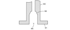
- FIG. 4 is a schematic cross-sectional view of the tip of a suction nozzle 90.
- FIG. 4 is a schematic explanatory diagram of a suction nozzle 90 viewed from a tip surface 91 side.
- FIG. 4 is a schematic explanatory diagram of the arrangement of an inspection camera 40 and an inspection light 50.
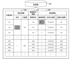
- FIG. 4 is an explanatory diagram of area information 85 stored in a storage unit 84.
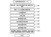
- 11 is a flowchart showing an example of a reference image setting process routine.
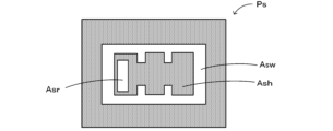
- FIG. 4 is a schematic explanatory diagram of a reference image Ps.
- FIG. 11 is a flowchart showing an example of an inspection processing routine.
- 11 is a flowchart showing an example of a region conversion inspection process routine.
- FIG. 4 is a schematic explanatory diagram of an inspection image Pt.
- FIG. 4 is a schematic explanatory diagram of a processed image Pa.
- 13 is a flowchart showing an example of an area calculation inspection processing routine.
- FIG. 1 is a schematic diagram of a cleaning inspection device 10.
- FIG. 2 is a schematic diagram showing an example of a mounting system 11.
- FIG. 3 is a schematic diagram of a suction nozzle 90.
- FIG. 4 is a schematic cross-sectional view of the tip of the suction nozzle 90.
- FIG. 5 is a schematic diagram of the suction nozzle 90 viewed from the tip surface 91 side.
- FIG. 6 is a schematic diagram of the arrangement of the inspection camera 40 and the inspection lighting 50. In FIG. 6, the dashed line indicates the direction of light from the inspection lighting 50, and the dashed line indicates the imaging direction of the inspection camera 40.
- FIG. 7 is an explanatory diagram of area information 85 stored in the memory unit 84.
- the cleaning and inspection device 10 is, for example, a device used in association with the mounting system 11, and is a device that cleans and inspects the suction nozzle 90 used in the mounting device 15 of the mounting system 11.
- the suction nozzle 90 used in the mounting device 15 of the mounting system 11 will be described as the main object of inspection.
- the mounting system 11 is configured as a production line in which mounting devices 15 that mount components P on a substrate S as an object to be processed are arranged in the transport direction of the substrate S.
- the object to be processed is described as a substrate S, but is not particularly limited as long as it mounts components P, and may be a three-dimensional substrate.
- the mounting system 11 includes a printing device 12, a print inspection device 13, a storage device 14, a mounting device 15, a mounting inspection device 16, a reflow oven (not shown), an automatic transport vehicle 17, and a loader 18 as a mobile work device.
- the printing device 12 is a device that prints a viscous fluid such as solder paste on the substrate S.
- the print inspection device 13 is a device that inspects the state of the printed solder and the substrate S.
- the storage device 14 is a device that stores and manages the feeder F that holds the components P.
- the mounting device 15 is a device that uses a suction nozzle 90 to pick up components P on the feeder F and mounts them on the board S.
- the mounting inspection device 16 is a device that inspects the state of the components P arranged on the board S.
- the mounting device 15 may be a mounting-inspection device that has the functions of the mounting inspection device 16.
- the reflow furnace is a device that reflows the board S.
- the automatic transport vehicle 17 is a vehicle that automatically transports the feeder F between a warehouse (not shown) and the storage device 14.
- the loader 18 is a device that automatically transports the feeder F between the storage device 14 and the mounting device 15.
- the printing device 12, the printing inspection device 13, the mounting device 15, and the mounting inspection device 16 are each equipped with an imaging unit that irradiates light onto an object to capture an image.
- the suction nozzle 90 is attached to the mounting head of the mounting device 15 that mounts components P, such as electronic components, on the board S.
- the suction nozzle 90 has an air passage that runs vertically through it in FIG. 3, and is configured to suck up the component P at the tip surface 91 using negative pressure supplied to the air passage.
- the suction nozzle 90 includes a body shaft 92, a flange 93, a nozzle shaft 94, and an identification code label 97.
- the body shaft 92 is formed in a tubular shape and is held by the suction head.
- the flange 93 is a disk-shaped member and is attached to one end side (the lower side in FIG. 4) of the body shaft 92.
- the nozzle shaft 94 is formed in a tubular shape with a hole portion 95.
- the hole portion 95 forms part of the air passage and includes a tapered portion 96 that widens toward the tip.
- the identification code label 97 is attached to the end face of the flange 93 on the tip surface 91 side.
- the identification code label 97 has a barcode or two-dimensional code that indicates identification information for identifying the suction nozzle 90.
- the cleaning and inspection device 10 is configured as a device for cleaning and inspecting the suction nozzle 90.
- the cleaning and inspection device 10 includes a nozzle moving mechanism 20, a cleaning unit 30, an inspection camera 40, an inspection light 50, a discharge box 60, a nozzle stocker 70, and a control device 80.
- the nozzle movement mechanism 20 is configured, for example, as an orthogonal robot that moves on two orthogonal axes.
- the nozzle movement mechanism 20 grasps the suction nozzle 90 with a holding chuck (not shown) and moves the suction nozzle 90 to the cleaning section 30, the inspection camera 40, the discharge box 60, and the nozzle stocker 70.
- the cleaning unit 30 is configured as a device that sprays a high-pressure fluid such as air or cleaning liquid onto the outer surface of the suction nozzle 90 to clean the suction nozzle 90 and dries the cleaned suction nozzle 90.
- a high-pressure fluid such as air or cleaning liquid
- the cleaning unit 30 sprays cleaning liquid onto the outer surface of the suction nozzle 90 to clean the suction nozzle 90, it may be equipped with a blowing device that blows off the cleaning liquid adhering to the suction nozzle 90.
- the inspection camera 40 is configured as an imaging device equipped with an imaging element, a lens, etc. As shown in FIG. 6, the inspection camera 40 is positioned so that it can capture an image of the suction nozzle 90 from the tip surface 91 side in the axial direction of the suction nozzle 90 when the suction nozzle 90 is placed at a predetermined imaging position.
- the inspection lighting 50 is configured to illuminate the tip surface 91 of the suction nozzle 90.
- the inspection lighting 50 includes a side-emitting light source 51 and a coaxial incident light source 52. As shown in FIG. 6, the side-emitting light source 51 irradiates light from an oblique direction onto the tip surface 91 of the suction nozzle 90.
- the coaxial incident light source 52 irradiates light onto the tip surface 91 of the suction nozzle 90 from a direction approximately perpendicular to the tip surface 91.
- the discharge box 60 is configured to isolate and house suction nozzles 90 that have been determined to require maintenance or inspection through an inspection, which will be described later. Although not shown, the discharge box 60 is divided into multiple spaces, and each of the divided spaces houses multiple suction nozzles 90 that have been determined to require maintenance or inspection.
- the nozzle stocker 70 is configured to isolate and store suction nozzles 90 that have been determined to be good products that do not require maintenance or inspection through an inspection described below. Although not shown, the nozzle stocker 70 is equipped with a storage pallet that stores multiple suction nozzles 90 that have been determined to be normal.
- the control device 80 is configured as a microprocessor centered on the CPU 82 as a judgment unit and a control unit, and controls the entire cleaning inspection device 10.
- the control device 80 includes a memory unit 84 capable of storing various information.
- the CPU 82 outputs a control signal to the nozzle moving mechanism 20 to control the operation and position of the nozzle moving mechanism 20.
- the CPU 82 outputs a command signal to the cleaning unit 30 to cause the cleaning unit 30 to clean and dry the suction nozzle 90.
- the CPU 82 outputs a control signal to the inspection camera 40 to cause the inspection camera 40 to capture an image of the suction nozzle 90.
- the CPU 82 outputs a control signal to the inspection illumination 50 to turn the inspection illumination 50 on and off.
- the memory unit 84 stores area information 85 corresponding to the identification information ID of the object, design information 86, and imaging condition information 87, as shown in FIG. 7.
- the area information 85 and imaging condition information 87 will be described later.
- the design information 86 is information about the design values of the suction nozzle 90.
- the design information 86 includes the shape of the tip of the suction nozzle 90 and the hole area, which is the area of the tip of the hole 95 of the suction nozzle 90.
- the CPU 82 of the control device 80 executes the reference image setting process routine of FIG. 8.
- the CPU 82 of the control device 80 controls the nozzle movement mechanism 20 to position, for example, multiple suction nozzles 90 in a new condition before use and/or in a good condition after maintenance at a predetermined shooting position (step S100).
- the CPU 82 executes an imaging process in which the inspection camera 40 is used to image the tip surface 91 of the suction nozzle 90 while turning on the inspection illumination 50 and irradiating the tip surface 91 of the suction nozzle 90 with light (step 110).
- imaging conditions such as the wavelength of the irradiated light, the irradiation direction, and the exposure time may be set to predetermined anti-reflection light conditions that reduce the amount of light reflected from the inner surface.
- the CPU 82 executes a contour recognition process for recognizing the contour of the tip surface 91 from the image captured in step S110 (step S120), binarizes the recognized outer diameter of the tip surface 91 (step S130), and obtains a reference image Ps (step S140).
- the binarization process in step S130 may be performed using Otsu's binarization method or the like.
- FIG. 9 is a schematic diagram of the reference image Ps.
- the reference image Ps includes an area Asw represented by white in FIG. 9, which is the light reflected from the end surface of the tip surface 91 of the suction nozzle 90, a reference hole area Ash represented by black in FIG. 9, which is the hole 95 inside the area Asw, and a reflected light area Asr represented by white in FIG.
- each area is described as “white” and “black”, respectively, but this is not limited to this, and the color of each area may be inverted.
- the CPU 82 obtains the position of the reflected light region Asr from the obtained reference image Ps (step S150), and calculates the reference hole area Ssh, which is the area of the tip of the hole 95 that is composed of the reflected light region Asr and the black reference hole area Ash that is the hole 95 in the reference image Ps (step S160).
- the CPU 82 acquires the identification information ID unique to the suction nozzle 90 (step S170).
- the identification information ID is acquired by capturing an image of the identification code label 97 of the suction nozzle 90 using the inspection camera 40.
- the CPU 82 then associates the identification information ID with the imaging condition information 87 in the imaging process of step S110, the reference image Ps, the shape, size such as area, and position of the reflected light region Asr, and the reference hole area Ssh, and stores them in the storage unit 84 as region information 85 (step S180), and ends the reference image setting process routine.
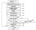
- FIG. 10 is a flow chart showing an example of an inspection process routine.
- the inspection process routine is executed after the cleaning unit 30 cleans the used suction nozzle 90.
- the CPU 82 of the control device 80 sets the suction nozzle 90 to be inspected, and controls the nozzle movement mechanism 20 to move the suction nozzle 90 to the inspection position (step S200).
- the CPU 82 acquires the identification information ID unique to the suction nozzle 90 (step S210).
- the identification information ID is acquired by capturing an image of the identification code label 97 of the suction nozzle 90 using the inspection camera 40 and reading the barcode or two-dimensional code attached to the identification code label 97.
- the CPU 82 acquires the design area Sd associated with the identification information ID and the imaging conditions of the reference image Ps from the information stored in the memory unit 84 (step S220), and executes an imaging process to image the tip surface 91 of the suction nozzle 90 under the acquired imaging conditions (step S230).
- the CPU 82 then executes an area conversion inspection process (step S240), and executes an area calculation inspection process (step S250).
- FIG. 11 is a flow chart showing an example of an area conversion inspection processing routine.
- the CPU 82 performs a recognition process for the outline of the tip surface 91 on the captured image (step S400), and performs a binarization process on the recognized outline to obtain an inspection image Pt (step S410).
- the CPU 82 may perform the binarization process using Otsu's binarization method.
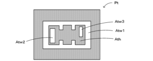
- FIG. 12 is a schematic explanatory diagram of the inspection image Pt.
- the inspection image Pt includes areas Atw1, Atw2, and Atw3, which are shown in white in FIG. 12, and a hole area Ath, which is shown in black in FIG. 12 and is the hole 95 inside area Atw1.
- the CPU 82 acquires area information 85 corresponding to the identification information ID from the storage unit 84 (step S420), and acquires a processed image Pa in which an area in the inspection image Pt corresponding to the reflected light area Asr of the reference image Ps is converted to a hole area Ath based on the area information 85 (step S430).
- FIG. 13 is a schematic explanatory diagram of the processed image Pa. In the processed image Pa, the area Atw2 of the inspection image Pt has been converted to a hole area Ath. It is considered that the reflected light area Asr of the reference image Ps is also captured in the inspection image Pt.
- the CPU 82 suppresses the influence of reflected light in the processed image Pa by converting the area Atw2 corresponding to the reflected light area Asr of the inspection image Pt to a hole area Ath.
- the area Atw3 remaining in the processed image Pa is considered to be an area in which reflected light due to attachments on the inner surface of the hole 95 is captured.
- the CPU 82 calculates the inspection hole area St as the area of the hole region Ath in the processed image Pa (step S440), and calculates the area ratio Rs by dividing the inspection hole area St by the design area Sd and multiplying the result by 100 using the following formula (1) (step S450).
- the CPU 82 determines whether the area ratio Rs is equal to or greater than the first judgment value Rsref1 and equal to or less than the second judgment value Rsref2 (step S460).
- the design area Sd does not include the effects of reflected light or attached matter. Therefore, the CPU 82 can determine the state of the suction nozzle 90 based on the area ratio Rs of the inspection hole area St to the design area Sd.
- step S460 the CPU 82 compares the area ratio Rs with the first and second judgment values Rsref1 and Rsref2.
- the first judgment value Rsref1 is a threshold value for judging whether the hole 95 is clogged with a deposit on the inner surface of the hole 95 or not. If the hole 95 is clogged, the area ratio Rs will be less than 100. Therefore, the first judgment value Rsref1 is set to a value less than 100, such as 85, 90, or 95.
- the second judgment value Rsref2 is a threshold value for judging whether the tip of the hole 95 is chipped. If the tip of the hole 95 is chipped, the area ratio Rs will be greater than 1. Therefore, the second judgment value Rsref2 is set to a value greater than 100, such as 105, 110, or 115.
- the CPU 82 determines that the hole 95 is not clogged or the tip of the hole 95 is not chipped, and the suction nozzle 90 is in a good condition (step S470), and ends the area conversion inspection processing routine.
- the CPU 82 determines that the hole 95 is clogged or the tip of the hole 95 is not chipped, and the suction nozzle 90 is not in a good condition (step S480), and ends the area conversion inspection processing routine.
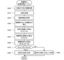
- FIG. 14 is a flow chart showing an example of an area calculation inspection processing routine.
- the CPU 82 performs a recognition process for the outline of the tip surface 91 on the captured image (step S500) in the same process as the area conversion inspection processing routine and steps S400, S410, and S420.
- the CPU 82 also performs a binarization process on the recognized outline to obtain an inspection image Pt (step S510), and obtains area information 85 corresponding to the identification information ID from the memory unit 84 (step S520).
- the CPU 82 calculates the deemed hole area at inspection Sa, which is the area of the black hole area Ath that is deemed to be the hole 95 in the inspection image Pt of FIG. 12 (step S530).
- the CPU 82 calculates the reflected light area Sr, which is the area of the reflected light area Asr on the inner surface of the suction nozzle 90, by subtracting the reference hole area Ssh based on the area information 85 acquired in step S520 from the design area Sd of the tip of the hole 95 using the following equation (2) (step S540).
- the CPU 82 also calculates the deemed hole area at inspection St by adding the reflected light area Sr to the deemed hole area at inspection Sa using the following equation (3) (step S550).
- the CPU 82 calculates the area ratio Rs [%] by dividing the inspection hole area St by the design area Sd and multiplying the result by 100 (step S560) in the same process as steps S450 and S460 of the area conversion inspection processing routine, and determines whether the area ratio Rs is equal to or greater than the first judgment value Rsref1 and equal to or less than the second judgment value Rsref2 (step S570). When the area ratio Rs is equal to or greater than the first judgment value Rsref1 and equal to or less than the second judgment value Rsref2, the CPU 82 determines that the hole 95 is not clogged and the tip of the hole 95 is not chipped, and that the suction nozzle 90 is in good condition (step S580), and ends the area calculation inspection processing routine.
- the CPU 82 determines that the hole 95 is clogged or the tip of the hole 95 is chipped, and that the suction nozzle 90 is not in good condition (step S590), and ends the area calculation inspection processing routine.
- step S260 when the CPU 82 ends the area conversion inspection process and the area calculation inspection process, it determines whether the condition of the object is good or not based on the inspection results (step S260).
- step S260 when the CPU 82 determines that the suction nozzle 90 is in a good state in both the area conversion inspection process and the area calculation inspection process, it determines that the condition of the object is good, and when the CPU 82 determines that the suction nozzle 90 is not in a good state in at least one of the area conversion inspection process and the area calculation inspection process, it determines that the condition of the object is not good.
- the inspection result is determined based on the results of two inspection processes, the area conversion inspection process and the area calculation inspection process, so that the inspection result can be determined with high accuracy.
- step S260 it may be determined that the condition of the object is good when the CPU 82 determines that the suction nozzle 90 is in a good state in at least one of the area conversion inspection process and the area calculation inspection process, and it may be determined that the condition of the object is not good when the CPU 82 determines that the suction nozzle 90 is not in a good state in both the area conversion inspection process and the area calculation inspection process.
- step S260 the CPU 82 controls the nozzle movement mechanism 20 to move the suction nozzle 90 to the nozzle stocker 70 (step S270). If the condition of the object is not good in step S260, the CPU 82 controls the nozzle movement mechanism 20 to move the suction nozzle 90 to the discharge box 60 (step S280).
- step S290 the CPU 82 stores the inspection results in the memory unit 84 (step S290) and determines whether or not inspection of all suction nozzles 90 to be inspected has been completed (step S300). If the inspection has not been completed, the CPU 82 returns to step S200, and if the inspection has been completed, the inspection process routine ends. In this way, the cleaning inspection device 10 can determine the state of the hole 95 by further reducing the influence of reflected light from the inner surface of the suction nozzle 90 as the target object.
- the CPU 82 of this embodiment corresponds to an example of a determination unit and control unit of the present disclosure
- the memory unit 84 corresponds to an example of a memory unit
- the hole portion 95 corresponds to an example of a hole portion
- the suction nozzle 90 corresponds to an example of an object
- the reference image Ps corresponds to an example of a reference image
- the reflected light area Asr corresponds to an example of a reflected light area
- the inspection image Pt corresponds to an example of an inspection image.
- this embodiment also clarifies an example of an inspection method of the present disclosure by explaining the operation of the cleaning inspection device 10.
- the memory unit 84 stores area information 85 as information on the reflected light area Asr that is the light reflected from the inner surface of the suction nozzle 90 in the reference image Ps obtained by capturing an image of the suction nozzle 90 in a predetermined reference state, and determines the state of the suction nozzle 90 using the area information 85 and the inspection image Pt obtained by capturing an image of the object during inspection.
- the cleaning inspection device 10 can more accurately determine the state of the suction nozzle 90 compared to a device that determines the state of the suction nozzle 90 using only the inspection image Pt.
- the memory unit 84 stores the position of the reflected light region Asr in the reference image Ps as region information 85, and the CPU 82 determines the state of the suction nozzle 90 by using the region corresponding to the reflected light region Asr in the inspection image Pt as the hole region Ath, so that the state of the object can be determined more accurately.
- the CPU 82 calculates the inspection hole area St, which is the area of the tip of the hole 95 at the time of inspection, based on the position of the reflected light area Asr in the inspection image Pt and treats the area corresponding to the reflected light area Asr as the hole 95, and determines the state of the suction nozzle 90 using the inspection hole area St and the design area Sd of the tip of the hole 95, thereby more accurately determining the state of the object.
- the memory unit 84 stores area information 85 including information on the reference hole area Ssh, and the CPU 82 determines the state of the object using the inspection hole area St, which is the area of the area considered to be the hole portion 95 in the inspection image Pt, and the reference hole area Ssh, so that the state of the object can be determined more accurately.
- the CPU 82 also determines the inspection hole area St as the sum of the reflected light area Sr obtained by subtracting the reference hole area Ssh from the design area Sd of the tip of the hole 95 and the inspection deemed hole area Sa calculated based on the area considered to be the hole 95 in the inspection image Pt, and uses the inspection hole area St and the design area Sd to determine the state of the object, thereby enabling a more accurate determination of the state of the object.
- the CPU 82 judges that the hole 95 of the suction nozzle 90 is clogged, and therefore it is possible to determine that the hole 95 of the suction nozzle 90 is clogged.
- the CPU 82 judges that there is a chip at the tip of the hole portion 95 of the suction nozzle 90, and therefore it is possible to determine that there is a chip at the tip of the hole portion 95 of the suction nozzle 90.
- the specified reference state includes a new state before use and/or a non-defective state after maintenance, so the state of the hole 95 of the suction nozzle 90 can be determined more accurately.
- the CPU 82 also functions as a control unit that associates the identification information IDs of the suction nozzle 90 with the information of the reflected light region Asr obtained from the reference image Ps and registers it in the region information 85.
- the CPU 82 obtains the identification information ID of the suction nozzle 90 that captured the inspection image Pt and obtains the region information 85 that corresponds to the obtained identification information ID, so that the state of the suction nozzle 90 can be determined with greater accuracy.
- the CPU 82 executes the area conversion inspection process and the area calculation inspection process, but since it is sufficient to execute at least one of the area conversion inspection process and the area calculation inspection process, it is possible to execute the area conversion inspection process without executing the area calculation inspection process, or to execute the area calculation inspection process without executing the area conversion inspection process.
- the CPU 82 determines whether the area ratio Rs is equal to or greater than the first judgment value Rsref1 and equal to or less than the second judgment value Rsref2 in the area conversion inspection process and the area calculation inspection process. However, the CPU 82 may only determine whether the area ratio Rs is equal to or greater than the first judgment value Rsref1. In this case, the CPU 82 can determine whether the hole 95 of the suction nozzle 90 is clogged. The CPU 82 may also only determine whether the area ratio Rs is equal to or less than the second judgment value Rsref2. In this case, the CPU 82 can determine whether the tip of the suction nozzle 90 is chipped.
- the CPU 82 determines the state of the suction nozzle 90 based on the position of the reflected light area Asr in the inspection image Pt, using the inspection hole area St, which is the area of the tip of the hole 95 at the time of inspection, as the hole 95, and the design area Sd.
- the CPU 82 since the CPU 82 only needs to determine the state of the suction nozzle 90 using the area corresponding to the reflected light area Asr in the inspection image Pt as the hole area Ath, it may also determine the state of the suction nozzle 90 using the inspection hole area St without using the design area Sd.
- the CPU 82 determines the inspection hole area St as the sum of the reflected light area Sr obtained by subtracting the reference hole area Ssh from the design area Sd of the tip of the hole 95 and the inspection deemed hole area Sa calculated based on the area considered to be the hole 95 in the inspection image Pt, and determines the state of the object using the inspection hole area St and the design area Sd.
- the CPU 82 may determine the state of the suction nozzle 90 using the inspection hole area St and the reference hole area Ssh without using the design area Sd.
- the reference image Ps is an image of the suction nozzle 90 in a new condition before use and/or in a good condition after maintenance, but the reference image Ps may also be an image of the suction nozzle 90 after it has been used to the extent that the hole is not clogged and the tip is not chipped.
- the suction nozzle 90 is imaged by the inspection camera 40, but the suction nozzle 90 may also be imaged by an imaging unit such as a mark camera for alignment used in the mounting device 15 or a parts camera for imaging the component P.
- an imaging unit such as a mark camera for alignment used in the mounting device 15 or a parts camera for imaging the component P.
- the inspection is performed by irradiating the suction nozzle 90 with light
- the object to be inspected is not particularly limited as long as it has a hole, and may be, for example, a component or a substrate.
- the object to be inspected may be an item other than that used in the mounting system 11.
- the hole of the object to be inspected may be a through hole or a bottomed hole.
- the nozzle inspection device disclosed herein may be configured as follows:
- An inspection method for irradiating a light onto an object having a hole comprising: a storage step of storing area information including information on a reflected light area that is a reflected light from an inner surface of the object in a reference image obtained by capturing an image of the object in a predetermined reference state, and/or information on a reference hole area that is an area of a tip of the hole that includes the reflected light area in the reference image; a determination step of determining a state of the object using the area information and an inspection image obtained by capturing an image of the object during inspection; Equipped with.
- area information is stored that includes information on the reflected light area, which is the light reflected from the inner surface of the object in a reference image captured of the object in a predetermined reference state, and/or information on the reference hole area, which is the area of the tip of the hole that includes the reflected light area in the reference image. Then, this inspection device determines the state of the object using the area information and an inspection image captured of the object during inspection. As a result, this inspection device can determine the state of the object more accurately than one that determines the state of the object using only the inspection image.
- This disclosure can be used in the inspection equipment manufacturing industry, etc.
Landscapes
- Physics & Mathematics (AREA)
- Health & Medical Sciences (AREA)
- Life Sciences & Earth Sciences (AREA)
- Chemical & Material Sciences (AREA)
- Analytical Chemistry (AREA)
- Biochemistry (AREA)
- General Health & Medical Sciences (AREA)
- General Physics & Mathematics (AREA)
- Immunology (AREA)
- Pathology (AREA)
- Investigating Materials By The Use Of Optical Means Adapted For Particular Applications (AREA)
Abstract
Description
孔部を有する対象物に対して光を照射して検査を行なう検査装置であって、
所定の基準状態である前記対象物を撮像した基準画像において前記対象物の内面での反射光とされる反射光領域の情報、及び/又は、前記基準画像において前記反射光領域を含んで構成される前記孔部の先端の面積である基準孔面積の情報を含む領域情報を記憶する記憶部と、
前記領域情報と、検査時に前記対象物を撮像した検査画像と、を用いて前記対象物の状態を判定する判定部と、
を備える検査装置。
St=Sa+Sr ・・・(3)
所定の基準状態である前記対象物を撮像した基準画像において前記対象物の内面での反射光とされる反射光領域の情報、及び/又は、前記基準画像において前記反射光領域を含んで構成される前記孔部の先端の面積である基準孔面積の情報を含む領域情報を記憶する記憶ステップと、
前記領域情報と、検査時に前記対象物を撮像した検査画像と、を用いて前記対象物の状態を判定する判定ステップと、
を備える。
Claims (11)
- 孔部を有する対象物に対して光を照射して検査を行なう検査装置であって、
所定の基準状態である前記対象物を撮像した基準画像において前記対象物の内面での反射光とされる反射光領域の情報、及び/又は、前記基準画像において前記反射光領域を含んで構成される前記孔部の先端の面積である基準孔面積の情報を含む領域情報を記憶する記憶部と、
前記領域情報と、検査時に前記対象物を撮像した検査画像と、を用いて前記対象物の状態を判定する判定部と、
を備える検査装置。 - 請求項1記載の検査装置であって、
前記記憶部は、前記基準画像における前記反射光領域の位置を前記領域情報として記憶し、
前記判定部は、前記検査画像の前記反射光領域に相当する領域を孔部領域として前記対象物の状態を判定する
検査装置。 - 請求項2記載の検査装置であって、
前記判定部は、前記検査画像において前記反射光領域の位置に基づいて前記反射光領域に相当する領域を前記孔部として検査時の前記孔部の前記先端の面積である検査時孔面積を算出し、前記検査時孔面積と前記孔部の前記先端の設計面積とを用いて前記対象物の状態を判定する
検査装置。 - 請求項1記載の検査装置であって、
前記記憶部は、前記基準孔面積の情報を含む前記領域情報を記憶し、
前記判定部は、前記検査画像の前記孔部とされる領域の面積である検査時孔面積と前記基準孔面積とを用いて前記対象物の状態を判定する
検査装置。 - 請求項4記載の検査装置であって、
前記判定部は、前記孔部の前記先端の設計面積から前記基準孔面積を減じて得られる反射光面積と、前記検査画像において前記孔部とされる領域に基づいて算出される検査時みなし孔面積と、の和を前記検査時孔面積とし、前記検査時孔面積と前記設計面積とを用いて前記対象物の状態を判定する
検査装置。 - 請求項3または5記載の検査装置であって、
前記判定部は、前記設計面積に対する前記検査時孔面積の割合が第1判定値未満のときには、前記孔部に詰まりがあると判定する
検査装置。 - 請求項3または5記載の検査装置であって、
前記判定部は、前記設計面積に対する前記検査時孔面積の割合が第2判定値を超えているときには、前記対象物の先端に欠けがあると判定する
検査装置。 - 請求項1または2記載の検査装置であって、
所定の前記基準状態は、使用開始前の新品状態及び/又はメンテナンス後の良品状態を含む
検査装置。 - 請求項1または2記載の検査装置であって、
前記基準状態の前記対象物を撮像した前記基準画像を取得し、前記基準画像から得られる前記反射光領域の情報及び/又は前記基準孔面積の情報と、前記対象物の識別情報と、を対応付けて前記領域情報に登録する制御部
を備え、
前記判定部は、前記検査画像を撮像した前記対象物の前記識別情報を取得し、取得した前記識別情報に対応する前記反射光領域の情報及び/又は前記基準孔面積の情報を取得する
検査装置。 - 請求項1または2記載の検査装置であって、
前記対象物は、基板に装着する部品を負圧を用いて吸着する吸着ノズルである
検査装置。 - 孔部を有する対象物に対して光を照射して検査を行なう検査方法であって、
所定の基準状態である前記対象物を撮像した基準画像において前記対象物の内面での反射光とされる反射光領域の情報、及び/又は、前記基準画像において前記反射光領域を含んで構成される前記孔部の先端の面積である基準孔面積の情報を含む領域情報を記憶する記憶ステップと、
前記領域情報と、検査時に前記対象物を撮像した検査画像と、を用いて前記対象物の状態を判定する判定ステップと、
を備える検査方法。
Priority Applications (4)
| Application Number | Priority Date | Filing Date | Title |
|---|---|---|---|
| CN202380096098.2A CN120917303A (zh) | 2023-03-28 | 2023-03-28 | 检查装置及检查方法 |
| DE112023006076.2T DE112023006076T5 (de) | 2023-03-28 | 2023-03-28 | Prüfvorrichtung und Prüfverfahren |
| JP2025509345A JPWO2024201724A1 (ja) | 2023-03-28 | 2023-03-28 | |
| PCT/JP2023/012567 WO2024201724A1 (ja) | 2023-03-28 | 2023-03-28 | 検査装置及び検査方法 |
Applications Claiming Priority (1)
| Application Number | Priority Date | Filing Date | Title |
|---|---|---|---|
| PCT/JP2023/012567 WO2024201724A1 (ja) | 2023-03-28 | 2023-03-28 | 検査装置及び検査方法 |
Publications (1)
| Publication Number | Publication Date |
|---|---|
| WO2024201724A1 true WO2024201724A1 (ja) | 2024-10-03 |
Family
ID=92903559
Family Applications (1)
| Application Number | Title | Priority Date | Filing Date |
|---|---|---|---|
| PCT/JP2023/012567 Ceased WO2024201724A1 (ja) | 2023-03-28 | 2023-03-28 | 検査装置及び検査方法 |
Country Status (4)
| Country | Link |
|---|---|
| JP (1) | JPWO2024201724A1 (ja) |
| CN (1) | CN120917303A (ja) |
| DE (1) | DE112023006076T5 (ja) |
| WO (1) | WO2024201724A1 (ja) |
Citations (3)
| Publication number | Priority date | Publication date | Assignee | Title |
|---|---|---|---|---|
| JP2002544524A (ja) * | 1999-05-14 | 2002-12-24 | エムブイ・リサーチ・リミテッド | マイクロビア検査システム |
| JP2009258069A (ja) * | 2008-03-19 | 2009-11-05 | Teijin Techno Products Ltd | 紡糸口金の孔内異物の検査装置および検査方法 |
| JP2021122046A (ja) * | 2018-11-28 | 2021-08-26 | 株式会社Fuji | ノズル管理機 |
-
2023
- 2023-03-28 JP JP2025509345A patent/JPWO2024201724A1/ja active Pending
- 2023-03-28 CN CN202380096098.2A patent/CN120917303A/zh active Pending
- 2023-03-28 DE DE112023006076.2T patent/DE112023006076T5/de active Pending
- 2023-03-28 WO PCT/JP2023/012567 patent/WO2024201724A1/ja not_active Ceased
Patent Citations (3)
| Publication number | Priority date | Publication date | Assignee | Title |
|---|---|---|---|---|
| JP2002544524A (ja) * | 1999-05-14 | 2002-12-24 | エムブイ・リサーチ・リミテッド | マイクロビア検査システム |
| JP2009258069A (ja) * | 2008-03-19 | 2009-11-05 | Teijin Techno Products Ltd | 紡糸口金の孔内異物の検査装置および検査方法 |
| JP2021122046A (ja) * | 2018-11-28 | 2021-08-26 | 株式会社Fuji | ノズル管理機 |
Also Published As
| Publication number | Publication date |
|---|---|
| CN120917303A (zh) | 2025-11-07 |
| DE112023006076T5 (de) | 2026-02-12 |
| JPWO2024201724A1 (ja) | 2024-10-03 |
Similar Documents
| Publication | Publication Date | Title |
|---|---|---|
| CN110678003B (zh) | Pcb阻焊检测修补一体机及工艺方法 | |
| EP1568985A2 (en) | Apparatus for surface inspection and method and apparatus for inspecting substrate | |
| KR102102874B1 (ko) | 자동 광학 검사 시스템 및 그 동작 방법 | |
| JP6838175B2 (ja) | 部品画像認識用学習済みモデル作成システム及び部品画像認識用学習済みモデル作成方法 | |
| KR102100889B1 (ko) | 다이 본딩 장치 및 반도체 장치의 제조 방법 | |
| TWI585394B (zh) | 動態式自動追焦系統 | |
| JP6108770B2 (ja) | 電子部品実装装置及び実装部品検査方法 | |
| CN101404868B (zh) | 电子部件安装方法 | |
| JP4434417B2 (ja) | プリント配線板の検査装置 | |
| CN111725086A (zh) | 半导体制造装置以及半导体器件的制造方法 | |
| KR20000007250A (ko) | 인쇄회로기판의 크림솔더 검사장치 및 검사방법 | |
| US11280744B2 (en) | Appearance inspection apparatus and appearance inspection method | |
| JP6795512B2 (ja) | 部品実装機 | |
| JP4760029B2 (ja) | 欠陥検査方法および欠陥検査装置 | |
| EP1595138B1 (en) | Image recognition apparatus and image recognition method | |
| US11924977B2 (en) | Device and method for inspecting adsorption nozzle | |
| CN120917303A (zh) | 检查装置及检查方法 | |
| JP6761477B2 (ja) | 部品実装装置および位置認識方法 | |
| CN116349420B (zh) | 图像处理装置、安装装置、安装系统、图像处理方法及安装方法 | |
| JP4387572B2 (ja) | 部品認識制御方法及び部品認識制御装置 | |
| CN116523882B (zh) | 一种基于视觉的光学目标区域准确率检测方法与系统 | |
| CN110470218A (zh) | 一种球头销视觉检测系统及球头销检测设备 | |
| Ko et al. | Enhancement of placement accuracy for SMD via development of a new illumination system | |
| WO2024224484A1 (ja) | 画像処理装置 | |
| JP3084744B2 (ja) | 半田付状態の外観検査方法 |
Legal Events
| Date | Code | Title | Description |
|---|---|---|---|
| 121 | Ep: the epo has been informed by wipo that ep was designated in this application |
Ref document number: 23930364 Country of ref document: EP Kind code of ref document: A1 |
|
| ENP | Entry into the national phase |
Ref document number: 2025509345 Country of ref document: JP Kind code of ref document: A |
|
| WWE | Wipo information: entry into national phase |
Ref document number: 2025509345 Country of ref document: JP |
|
| WWE | Wipo information: entry into national phase |
Ref document number: CN2023800960982 Country of ref document: CN Ref document number: 202380096098.2 Country of ref document: CN |
|
| WWE | Wipo information: entry into national phase |
Ref document number: 112023006076 Country of ref document: DE |
|
| WWP | Wipo information: published in national office |
Ref document number: 202380096098.2 Country of ref document: CN |
|
| WWP | Wipo information: published in national office |
Ref document number: 112023006076 Country of ref document: DE |
|
| 122 | Ep: pct application non-entry in european phase |
Ref document number: 23930364 Country of ref document: EP Kind code of ref document: A1 |